Article

Proposal and Validation of a Pyro Conductor Switch-Based FCL for DC Distribution System Protection

Department of Electronic Engineering, Hanyang University, Ansan 15588, Republic of Korea
*
Author to whom correspondence should be addressed.
Energies 2025, 18(13), 3441; https://doi.org/10.3390/en18133441
Submission received: 4 June 2025 / Revised: 24 June 2025 / Accepted: 27 June 2025 / Published: 30 June 2025
(This article belongs to the Section F2: Distributed Energy System)

Abstract

With the increasing deployment of DC power systems, particularly in DC distribution systems, there is a growing demand for rapid and effective fault current limiting solutions. Conventional fault current limiters (FCLs) often suffer from limitations in terms of response time, size, and operational complexity. As a solution to these challenges, this paper proposes a hybrid FCL based on a pyro conductor switch (PCS), which combines passive limiting elements with an active switching mechanism. The proposed PCS FCL consists of a pyro fuse, an IGBT switch, a limiting inductor, and a damping resistor. Upon fault detection, the IGBT switch is first turned off to initiate current transfer into the limiting branch. Subsequently, the pyro fuse operates by explosively severing the embedded conductor using a pyrotechnic charge, thereby providing galvanic isolation and reinforcing current commutation into a high-impedance path. This operational characteristic enables effective fault current suppression without requiring complex control or real-time sensing. A detailed analysis using PSCAD/EMTDC simulations was conducted to evaluate the current limiting characteristics under fault conditions, and a prototype was subsequently developed to validate its performance. The simulation results were verified through experimental testing, indicating the limiter’s ability to reduce peak fault current. Furthermore, the results demonstrated that the degree of current limitation can be effectively designed through the selection of appropriate current limiting parameters. This demonstrates that the proposed PCS-based FCL provides a practical and scalable solution for improving protection in DC power distribution systems.

1. Introduction

The increasing deployment of DC distribution systems in renewable energy integration, shipboard microgrids, and high-efficiency data centers has introduced new challenges regarding fault protection. Unlike AC systems, DC networks lack natural current zero-crossing, making fault current interruption more difficult and resulting in prolonged arcing and higher stress on switching devices [1,2]. Moreover, DC fault currents rise rapidly due to the low impedance of the system, and their effective suppression requires fast-acting protection mechanisms, such as those demonstrated in hybrid MMC-based HVDC systems [3].
While DC CBs are essential for protection, their performance may be constrained during severe transient events, due to inherent limitations in terms of switching speed and energy dissipation capacity [4]. Hybrid-type DC CBs, which combine mechanical and solid-state switches, have been proposed to improve interruption speed. However, they still face practical challenges such as high implementation costs, a bulky structure, and increased component stress during fault clearing, which hinder their adoption in compact or large-scale DC grid applications [5,6].
To address these limitations, fault current limiters (FCLs) have been explored as auxiliary protection devices that mitigate the stress imposed on DC circuit breakers. By suppressing peak fault currents before interruption, FCLs enhance protection coordination and improve system reliability [7]. Among the various technologies, superconducting FCLs (SFCLs) have gained attention due to their ability to introduce rapid impedance changes with negligible steady-state losses. However, their dependence on cryogenic infrastructure limits their applicability in practical MVDC and HVDC systems. Nevertheless, recent studies have demonstrated their feasibility, for example, in an overvoltage-triggered SFCL scheme for multiterminal HVDC networks [8], as well as in hybrid SFCL topologies combining resistive and superconducting paths for MVDC shipboard applications [9]. Additional variants, such as modified flux-coupling-type SFCLs with parallel superconducting branches, have also been studied for their fault current limiting performance and applicability to DC system protection [10].
Due to the challenges associated with cryogenic cooling and system complexity, non-superconducting FCL approaches have gained increasing attention. These include self-adaptive FCLs integrated with hybrid solid-state DC breakers [11], impedance-modulated circuits for MMC-based HVDC systems [12], and self-powered solid-state FCLs tailored for VSC-based DC distribution networks [13]. While these techniques offer advantages in terms of selectivity and response speed, several limitations remain. Fuse-based methods suffer from non-reusability and limited tunability, while control-intensive non-superconducting FCLs depend on real-time sensing and active coordination, which complicates system integration.
In contrast, the proposed PCS-based fault current limiter (FCL) achieves rapid fault isolation through passive triggering and minimal control circuitry, while maintaining structural simplicity and adaptability. Conventional fuse-based solutions suffer from non-reusability and limited tunability, whereas control-intensive FCLs rely on real-time sensing and coordination, complicating system integration. To overcome these limitations, pyro conduction switches (PCSs) and pyro-fuses have emerged as compact and effective alternatives for DC fault isolation. These devices utilize pyrotechnic actuators to achieve ultra-fast mechanical disconnection with minimal control overhead [14]. Their effectiveness has been demonstrated in applications such as eVTOL systems [15] and fusion-based protection devices [16,17], where arc dynamics have been further analyzed using enhanced Mayr and Schavemaker models [18]. However, their application as FCLs in DC distribution systems remains limited, especially in configurations requiring coordination with auxiliary protection components [19].
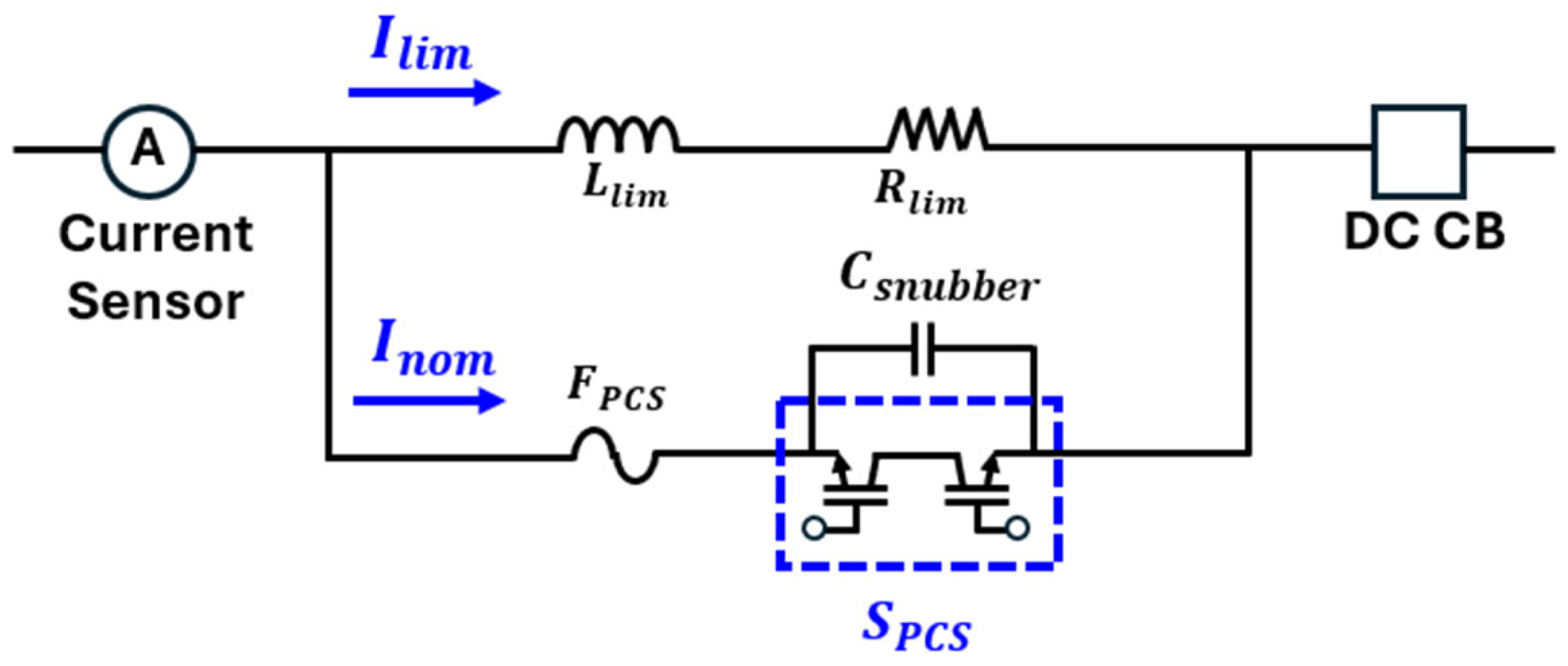
In this study, a hybrid FCL incorporating a PCS is proposed for DC distribution systems. The proposed design employs a pyro fuse for fast isolation, an IGBT switch to control conduction, a limiting inductor to moderate the fault current’s rise rate, and a damping resistor for energy absorption. Once a fault is detected, the main conduction branch is broken, redirecting the current into a current limiting branch, which suppresses the fault peak and reduces stress on the DC circuit breaker.
Therefore, this study proposes and validates a compact and tunable fault current limiter (FCL) based on a pyro conductor switch (PCS) for application in DC distribution systems. The main contributions of this research are as follows: the development of a hybrid FCL topology combining passive triggering and fast current suppression using a pyro fuse and IGBT; the establishment of a PSCAD/EMTDC-based simulation framework to evaluate performance under various system conditions; the construction and testing of a laboratory-scale prototype to validate the simulation results; and the demonstration of performance tunability through parametric analysis, supporting practical deployment in MVDC protection applications. These contributions collectively aim to advance scalable and reliable protection strategies for next-generation DC distribution networks.

2. Proposed PCS Fault Current Limiter

Pyro Conductor Switch (PCS) Fault Current Limiter

Figure 1 illustrates the topology of the proposed pyro conductor switch (PCS)-based FCL, which was developed to enhance overcurrent protection in DC power systems [20]. The configuration is composed of key components, including a pyro fuse ( F P C S ), an IGBT-based switch ( S P C S ), a limiting inductor ( L l i m ), a damping resistor ( R l i m ), and a snubber capacitor ( C s n u b b e r ). These elements are integrated into a compact module that interfaces with a DC CB, forming a coordinated protection scheme. This layout supports modular integration and effective coordination between passive and active protection elements in DC networks. Building on this structure, the proposed configuration provides a compact and scalable protection solution by combining certain elements.
The proposed configuration offers a compact and modular protection solution by combining energy-absorbing components with fast-switching functionality. The PCS-based FCL design incorporates both passive limiting and fast-acting switching components to achieve compactness and reliability. Recent developments have proposed hybrid fault-limiting structures that combine passive and solid-state elements that are primarily for use in microgrid protection applications [21].
Figure 2 illustrates the operating principle of the proposed PCS-based fault current limiter across four sequential stages, each representing a distinct system condition and corresponding current behavior. In the normal state shown in (a), the system operates under steady conditions, and the load current flows through the low-impedance conduction branch consisting of the F P C S and the turned-on S P C S , bypassing the current limiting path R l i m and L l i m . As a result, only conduction loss occurs, which is relatively small compared to the potential loss in the limiting branch. Power dissipation in R l i m and L l i m remains negligible until fault-induced commutation redirects the current. In this state, the system current equals the nominal operating current.
I n o m ( t ) = I s y s ( t )
The limiting components ( L l i m and R l i m ) are bypassed, and the pyro fuse F P C S remains intact, resulting in negligible conduction losses.
In (b), a fault triggers the controller, causing it to turn off S P C S , redirecting the current into the current limiting branch. The resulting fault current follows the transient response determined by the resistance and inductance of this branch:
I f a u l t ( t ) = V D C R s y s ( 1 e R s y s L s y s t )
This expression reflects the exponential growth of fault current over time, governed by the system time constant τ = L s y s R s y s . The current continues to rise until the F P C S operates, disconnecting the low-impedance branch.
In (c), once F P C S opens, the fault current is fully diverted into the limiting path, which is composed of L l i m and R l i m . This stage is characterized by current attenuation via energy absorption in the resistive-inductive branch. The current follows an exponential decay process:
I f a u l t ( t ) = I 0 · e R s y s + R lim L s y s + L lim t
In (d), after the fault current has been sufficiently limited, the DC circuit breaker (DC CB) performs the final interruption, isolating the faulted section. At this stage, the current is fully interrupted:
I f a u l t ( t ) = 0 ,   for   t t clear
This completes the fault protection sequence by effectively interrupting the limited fault current, thereby preventing further propagation of the fault and ensuring the safe isolation of the affected section.

3. PCS Fault Current Limiter Modeling

3.1. DC Source Configuration

Figure 3 presents two types of DC source configurations developed for constructing a test bed simulation, aimed at evaluating the performance of the proposed PCS fault current limiter. In order to accurately model the PCS fault current limiter behavior under different supply conditions, both an ideal DC source and a practical full-bridge rectifier were implemented and comparatively analyzed. Similar full-bridge rectifier configurations have been adopted in previous studies for the testing of DC protection devices such as DC CBs and fault generators. These configurations provide a stable and controllable DC source environment that is suitable for evaluating fault interruption performance under practical operating conditions [22].
In Figure 3a, an ideal DC source is configured to provide a constant output voltage V D C with zero internal impedance. This source model offers a stable and disturbance-free supply, serving as a reference for evaluating the transient behavior of the PCS without influence from source-side fluctuations. The current flowing through the system, which consists of system resistance and system inductance, follows this differential equation:
V D C = I d c . a ( t ) · R s y s + L s y s · d I d c . a ( t ) d t
For an initial current I 0 = 0, the expression simplifies to:
I d c . a ( t ) = V D C R s y s ( 1 e R s y s L s y s t )
This model provides an idealized baseline to benchmark the current limiting response of the PCS. In contrast, Figure 3b illustrates a full-bridge rectifier-based DC source, reflecting practical implementation considerations. The rectifier converts three-phase AC voltages into DC via a six-diode configuration, with a capacitor C connected at the output. The resulting output voltage V C ( t ) includes ripple and dynamic variation due to the interaction between the charging current and the load. The dynamic relationship between the capacitor voltage V C ( t ) and the load current I d c . b is governed by the capacitor’s charging and discharging behavior. This relationship can be expressed as:
C · d V C ( t ) d t = I charging ( t ) I d c . b ( t )
During this discharge period, the charging current becomes zero, such that I c h a r g i n g ( t ) = 0 . Under this condition, the governing equation can be simplified accordingly:
d V C ( t ) d t = I d c . b ( t ) C
Assuming that I d c . b t remains approximately constant over short discharge intervals (valid under low ripple conditions and for inductive loads), the capacitor voltage decreases linearly. Over the ripple period T r , defined by the diode conduction cycle, the peak-to-peak ripple voltage can be approximated as:
Δ V C I d c . b · T r C
For a six-pulse three-phase rectifier, the ripple period T r is equal to one-sixth of the AC input cycle. This leads to T r = 1 6 f , where f represents the AC supply frequency. Substituting this into the ripple voltage expression yields:
Δ V C I d c . b 6 f · C
This expression shows that the ripple magnitude decreases as the capacitance and supply frequency increase, indicating an inverse proportionality. A sufficiently large capacitor minimizes voltage fluctuation and provides a more stable DC supply to the PCS limiter circuit. Meanwhile, the output current I d c . b t is smoothed by the system inductance L s y s and remains relatively constant, further decoupling load disturbances from the voltage ripple.
This analysis enables a quantitative comparison between the ideal DC source in Figure 3a and the practical full-bridge rectifier source in Figure 3b, providing insight into how source characteristics influence PCS fault current limiting behavior under various operating conditions.
Figure 4 presents the simulation results corresponding to the DC source configurations introduced in Figure 3. This simulation was conducted with a rated voltage of 600 V and a rated current of 60 A, with the load resistance set to 10 Ω. At t = 0.05 s, the making switch is closed to initiate current flow, allowing for a comparative analysis of the ideal DC source and the full-bridge rectifier configuration. In Figure 4a, the ideal DC source maintains a constant voltage output, while the full-bridge rectifier shows a ripple in its output voltage, due to the capacitor’s charging and discharging behavior. Despite this ripple, the average voltage level is close to that of the ideal source. Figure 4b shows the corresponding load current. The current supplied by the ideal DC source increases smoothly and reaches a steady value, while the current from the full-bridge source exhibits a similar rise, with minor oscillations caused by voltage ripple. These results indicate that the full-bridge rectifier can effectively replicate ideal DC conditions and is suitable for use in constructing a test bed for evaluating the PCS fault current limiter under practical operating scenarios.

3.2. PSCAD/ETMDC Simulation

Figure 5 shows the PSCAD/EMTDC-based simulation circuit diagram that was developed to evaluate the performance of the PCS fault current limiter. The DC source is implemented using a full-bridge rectifier and capacitor, supplying current to a resistive load through the PCS fault current limiter. The PCS fault current limiter consists of two branches: the main conduction path, containing S P C S and F P C S , and the current limiting path, composed of R l i m and L l i m . The PCS fault current limiter is designed to divert the current into a high-impedance path upon fault detection, enabling the effective limitation of the fault current during transient conditions, a design that aligns with existing simulation-based studies on pyrotechnic FCL applications [23].
The operating sequence of the switching elements ( S m a k , S R e l a y , and S P C S ) used to control the PCS fault current limiter is illustrated in Figure 6. At the start of the simulation, both the making switch and the IGBT switch are turned on, enabling the current to flow through the low-impedance main conduction path of the PCS fault current limiter. The IGBT switch is turned off at t = 0.2 ms, which immediately redirects the current into the high-impedance current-limiting path, which consists of R l i m and L l i m . The DC relay remains turned on during this period to maintain the continuity of the current flow. At t = 0.02 s, the DC relay is opened, thereby serving as the final interruption stage that completely disconnects the already-limited current. The making switch remains turned on until t = 0.05 s to provide a stable power supply throughout the simulation. This switching sequence enables a controlled evaluation of the PCS fault current limiter’s ability to limit and interrupt the current in response to a gradual current rise, without applying a fault condition.
Figure 7 shows the load current waveforms that were obtained from PSCAD simulations with and without the proposed PCS fault current limiter. At t = 0.05 s, the making switch is turned on, initiating current flow through the circuit. Without current limiting activity, the current rapidly increases and reaches a peak of approximately 60 A. In contrast, when the limiter is applied, the current is effectively suppressed to below 50 A during the current limiting period of 0.02 s. In this case, the load resistance is fixed at 10 Ω, and the current limiting parameters are set to R l i m = 2 Ω and L l i m = 12 mH. At t = 0.07 s, the DC relay opens, resulting in a complete current interruption in both cases. These results demonstrate that the proposed PCS-based current limiter operates as intended, achieving effective transient current suppression during the limiting period and ensuring proper insulation through subsequent relay operation.

3.3. Parameter Study

To evaluate the impact of the various current limiting parameters, four cases were defined by varying the R l i m and inductance L l i m values of the PCS fault current limiter. Figure 8 presents the load current waveforms for Cases I through IV, where the making switch is turned on at 0.05 s and the DC relay operates at 0.07 s. The t l i m is set to 0.02 s in all cases.
As shown in the figure, higher values of R l i m and L l i m lead to more effective current suppression. Table 1 summarizes the limiting performance, including the peak L l i m and the corresponding limiting percentage. The results indicate that the proposed limiter allows for adjustable fault current suppression by tuning its limiting parameters. Specifically, the limiting percentage increases from 19.3% in Case I to 46.2% in Case IV, demonstrating the feasibility of parameter-based optimization in PCS fault current limiter design.

4. PCS Fault Current Limiter Prototype

Based on the simulation results, which verified the effectiveness of the proposed PCS fault current limiter under various operating conditions, a prototype was designed and developed to demonstrate its performance in a laboratory setting. The experimental setup was constructed to replicate the key parameters observed in the simulations, enabling a consistent and meaningful evaluation of the limiter’s current suppression and interruption characteristics.

4.1. Prototype and Test Bed

The circuit diagram shown in Figure 9 presents the experimental test-bed configuration that was developed to evaluate the performance of the proposed PCS fault current limiter. The setup consists of two main sections: the DC power source and the PCS facility. On the DC power source side, a three-phase diode bridge rectifier converts the AC input ( V A C . a ,   V A C . b ,   V A C . c ) into DC voltage ( V c ), which is stabilized using a capacitor, C. This portion represents the controlled DC power supply that was used in the experiment.
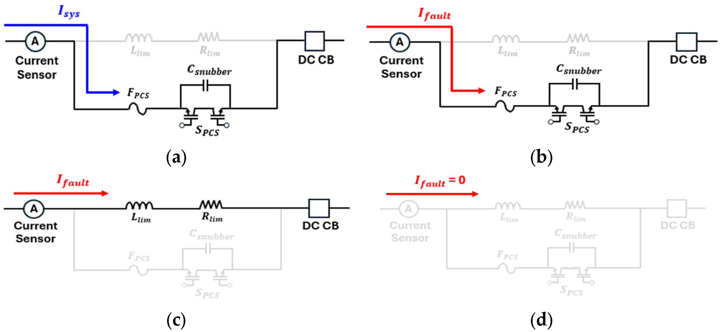
On the PCS facility side, the PCS fault current limiter circuit is implemented. When the making switch ( S m a k ) is closed, the current flows through the current limiting components R l i m and L l i m . The parallel path includes the S P C S , C s n u b b e r , and F P C S . Under normal operating conditions, S P C S remains turned on to bypass the limiter. When S m a k is turned on, S P C S turns off in order to force the current through the limiting path ( R l i m and L l i m ), thereby suppressing the current. A current sensor is placed before the load to measure I l o a d and the S r e l a y is responsible for the final current interruption. The load is represented by R l o a d , which is a fixed resistive element with a value of 10 Ω.
The experimental setup, as illustrated in Figure 10, consists of a DC power source, a PCS fault current limiter unit, and a load system integrated with the measurement and control components. The key components, including the limiting elements ( R l i m and L l i m ), IGBT switches, pyro fuse, and DC relay, are installed in a modular rack-based structure to facilitate ease of configuration and monitoring. The controller unit is responsible for managing the timing and coordination of switching elements during the test sequences.
Table 2 summarizes the main specifications of the devices used in the test bed. Both the making IGBT and PCS IGBT are rated at 1700 V and 150 A, with a short-term withstanding capability of up to 950 A. The high-speed pyro fuse is capable of interrupting 60 A within 50–80 ms under 600 V a c or 500 V d c conditions. The DC relay operates with a rated voltage of 1000 Vdc and a current rating of 100 A, enabling safe disconnection after fault current suppression. The current sensor used in this study is the HCP8150A model from Cybertek (Shenzhen City, China), with a continuous maximum input range of 150 A.

4.2. Test Results

The experiments were performed under uncontrolled ambient laboratory conditions as environmental factors such as temperature and humidity were not expected to significantly affect the results. Due to the nature of the test setup, each condition was verified through a single trial, which was sufficient to confirm functional operation.
Figure 11 presents the experimental measurement results for the PCS fault current limiter during a 50 A current limiting test. At t = 0 s, the making switch is turned on, allowing current to flow through the PCS circuit. Initially, the IGBT switch conducts and forms the main current path. At t = 0.2 ms, the IGBT is turned off, causing the current to be redirected into the current-limiting branch. The current is then suppressed to reach a steady value, indicated as the limiting current, and is maintained for approximately t l i m = 0.024 s.
Figure 12 presents a comparison between the simulation and the experimental results of the PCS fault current limiter operation under Case I conditions. The plot shows the load current profiles obtained from the PSCAD simulation and experimental measurement during the current limiting process. The S P C S is turned on at time zero, initiating current flow through the system. As the current increases, the PCS fault current limiter activates its limiting function, and the current stabilizes at approximately 50 A. This limiting condition is maintained for a duration of about t l i m = 0.024 s.
The experimental results closely follow the simulation curve, in terms of both current magnitude and response time. Minor oscillations observed in the experimental data reflect real-world switching and measurement noise, but the overall waveform trend aligns well with the simulated response. At approximately 24 ms, the DC relay is turned on, resulting in a sharp drop in current and a successful interruption. This close agreement between PSCAD and experimental results indicates the accuracy of the simulation model and suggests that the PCS fault current limiter performs reliably under the tested conditions.
Figure 13 presents the experimental results for four case studies (Case I–Case IV), demonstrating the current limiting performance of the PCS fault current limiter under varying system impedance conditions. The figure shows the measured load current profiles after the making switch is turned on at t = 0 s. As the R l i m and L l i m increases, the limited current decreases accordingly, indicating that the PCS fault current limiter can adjust its performance according to circuit conditions. The specific resistance, inductance, limited current, and calculated limiting percentages for each case are summarized in Table 3. The results show that adjusting the current-limiting parameters, such as R s y s and L s y s , enables effective control of fault current suppression. For example, Case I yields the highest limited current due to lower impedance, while Case IV achieves the lowest fault current with higher limiting values. These findings demonstrate the tunability of the proposed FCL design to meet various protection requirements. Figure 14 illustrates the sum of energy dissipated in R s y s and L s y s under different system conditions, showing an increasing trend up to Case III, followed by a slight decrease in Case IV due to a greater current reduction. The interruption time remains consistently at around 21 ms across all cases and is primarily determined by the operating delay of the DC relay, rather than a variation in system impedance. It should be noted that the applied fault current remained below the pyro fuse activation threshold and no melting or disconnection occurred. The observed suppression reflects the system’s behavior prior to fuse triggering. Further tests under higher fault current conditions are planned to evaluate full-scale fuse operation.
The impedance-dependent limiting characteristics demonstrated in this study are consistent with previous findings, where resistance and inductance values were shown to directly influence the fault current suppression in DC systems. In particular, an R–L-based current limiting method, when applied to a ± 10 kV VSC-DC distribution network, indicated that increasing the impedance enhances current suppression effectiveness, which supports the tunability of the proposed PCS-based FCL design [24]. In addition, the close agreement between the simulation results and the experimental measurements indicates the accuracy and reliability of the developed model. Such consistency aligns with prior studies that emphasized the role of simulation-based design for optimizing protection strategies in low-voltage DC distribution networks [25].
Experimental validation efforts in the literature also demonstrate that solid-state fault current limiters can achieve a limiting performance that closely matches simulation predictions when the switching sequences and impedance parameters are properly coordinated [26,27]. These results collectively strengthen the practical feasibility of the PCS-based FCL architecture proposed in this work, particularly for compact and modular DC distribution environments.

5. Discussion

The proposed PCS-based FCL was experimentally validated under four distinct limiting impedance conditions, demonstrating strong consistency with the simulation results. The measured limited current values and suppression rates closely matched those obtained from PSCAD/EMTDC simulations, indicating the validity of the proposed model and its applicability to practical DC protection scenarios. This consistency indicates that the adopted simulation methodology can reliably predict real-world performance, thereby reducing the need for repeated hardware iterations during the design phase.
Variations in the limiting branch parameters clearly demonstrated the dependence of current suppression on impedance. In particular, increasing both resistance and inductance led to a notable reduction in peak fault current, validating the tunability of the PCS-based FCL. Such adjustability allows the limiter to be configured for diverse system protection requirements, including selective operation and coordination with other protective devices. The switching components, including the IGBT and pyro conductor, operated stably and consistently in all test cases, enabling the rapid diversion of fault current into the limiting path.
Beyond its technical performance, the PCS-based FCL features a modular topology that facilitates adaptation to various voltage levels through parameter scaling. The use of passive components and a simple control scheme further enhance its integration potential. Future work should assess the thermal endurance of the limiting resistor under repeated fault conditions and examine the long-term mechanical reliability of the PCS, including its susceptibility to premature triggering caused by vibration or ambient heat. Moreover, as the PCS is a single-use switching component, its deployment may raise cost and maintenance concerns, particularly in systems requiring frequent fault handling or high availability. These practical considerations will be essential for extending the applicability of the proposed design to distributed and multi-terminal DC systems. In addition, the current ripples observed in the experimental waveforms (e.g., in Figure 4) suggest that performance could be improved further by implementing suitable filtering and control strategies, especially for sensitive downstream equipment.

6. Conclusions

In this study, a PCS-based fault current limiter was proposed and validated for DC distribution systems through PSCAD/EMTDC simulations and laboratory-scale experiments. The limiter demonstrated tunable fault current suppression, with peak current reductions ranging from 17.2% to 47.7%, consistent interruption times of approximately 21 ms, and maximum energy dissipation reaching 196.6 J. The close agreement between the simulation and the experimental results supports the reliability of the proposed modeling framework for predictive design and performance tuning.
The modular architecture and minimal control requirements make the PCS-based FCL a promising solution for compact and scalable DC protection. Potential applications include DC-fed data centers, EV charging infrastructure, and renewable-integrated microgrids. While the proposed limiter showed stable operation under low-voltage conditions, further validation at medium-voltage levels is needed to assess its dielectric strength and endurance under repetitive fault conditions. Additionally, the one-time usability of the pyro fuse remains a practical limitation.
Future work will enhance the thermal and mechanical robustness of a PCS-based FCL for use in repeated fault conditions and high-energy environments, including improvements in pyro housing durability and thermal management. The design will be scaled to MVDC levels, with an emphasis on insulation coordination, and protection schemes will be developed to enable selective coordination with high-speed DC breakers in multi-terminal networks.

7. Patents

The proposed protection method is covered by Korean Patent No. 10-1996510, titled “Fault Current Limiting Device and Control Method for DC Grids,” granted by the Korean Intellectual Property Office (KIPO) on 28 June 2019.

Author Contributions

Conceptualization, I.K. and B.-W.L.; methodology, I.K. and Y.-J.K.; validation, Y.-J.K. and J.-C.L.; formal analysis, I.K. and Y.-J.K.; writing—original draft preparation, I.K.; writing—review and editing, B.-W.L.; supervision, B.-W.L. All authors have read and agreed to the published version of the manuscript.

Funding

This research was funded by the Korean Institute of Energy Technology Evaluation and Planning (KETEP), grant number 20225500000150. The APC was funded by the authors.

Data Availability Statement

The data are not publicly available, due to institutional confidentiality agreements.

Conflicts of Interest

The authors declare no conflicts of interest. The funders had no role in the design of the study; in the collection, analyses, or interpretation of data; in the writing of the manuscript; or in the decision to publish the results.

Abbreviations

The following abbreviations are used in this manuscript:
MDPIMultidisciplinary Digital Publishing Institute
DOAJDirectory of open access journals
TLAThree-letter acronym
LDLinear dichroism

References

  1. Jovcic, D.; Ahmed, K. High Power Converters for AC and DC Transmission; Wiley-IEEE Press: Hoboken, NJ, USA, 2015. [Google Scholar] [CrossRef]
  2. Callavik, M.; Blomberg, A.; Häfner, J.; Jacobson, B. The Hybrid HVDC Breaker: An Innovation Breakthrough Enabling Reliable HVDC Grids; ABB Grid Systems Technical Paper; ABB: Zürich, Switzerland, 2012. [Google Scholar]
  3. Xu, J.; Zhao, X.; Jing, H.; Zhao, C. DC Fault Current Clearance at the Source Side of HVDC Grid Using Hybrid MMC. IEEE Trans. Power Deliv. 2020, 35, 140–148. [Google Scholar] [CrossRef]
  4. Wang, J.; Li, Y.; Zhang, H. Successful fault current interruption on DC circuit breaker. IET Power Electron. 2015, 8, 2345–2352. [Google Scholar] [CrossRef]
  5. Liu, S.; Yuan, Z.; Chen, J.; Chen, Y.; Yu, M.; Liu, Z.; Geng, Y. A Cost-Effective Current-Limiting Hybrid DC Circuit Breaker Based on Hybrid Semiconductors. Electronics 2024, 13, 1948. [Google Scholar] [CrossRef]
  6. Zhang, H.; Li, G.; Wang, Y.; Liu, C.; Chen, Z. A Dual-Bridge Hybrid DC Circuit Breaker. In Proceedings of the 23rd European Conference on Power Electronics and Applications (EPE’21 ECCE Europe), Ghent, Belgium, 6–10 September 2021; pp. 1–10. [Google Scholar] [CrossRef]
  7. Esmaeili, Z.; Heydari, H. A Review of the Effect of Common Fault Current Limiters (FCLs) on Power Systems Reliability. IET Energy Syst. Integr. 2025, 7, 45–56. [Google Scholar] [CrossRef]
  8. Yang, B.; Wang, Y.; Liu, Z.; Yuan, W.; Yuan, L. Design and Application of Superconducting Fault Current Limiter in a Multi-Terminal HVDC Systems. IEEE Trans. Appl. Supercond. 2017, 27, 5601405. [Google Scholar] [CrossRef]
  9. Zhou, Y.; Ren, L.; Xu, Y.; Shi, J. Optimal Application Research of Superconducting Fault Current Limiters on Medium Voltage Direct Current Shipboard Power System. Sci. Rep. 2025, 15, 14568. [Google Scholar] [CrossRef] [PubMed]
  10. Chen, L.; Hu, R.; Deng, X.; Tang, J.; Dong, H.; Wang, X.; Chen, H.; Islam, R. Study of Modified Flux-Coupling-Type SFCLs for Stability Improvement of a Multi-Machine Power System Based on Energy Function. IEEE Trans. Appl. Supercond. 2021, 31, 5601405. [Google Scholar] [CrossRef]
  11. Yaqobi, M.A.; Matayoshi, H.; Prabaharan, N.; Takahashi, H.; Hemeida, A.M.; Senjyu, T. Interconnected Standalone DC Microgrid Fault Protection Based on Self-Adaptive DC Fault Current Limiter with Hybrid Solid-State Circuit Breaker. AIMS Energy 2021, 9, 991–1008. [Google Scholar] [CrossRef]
  12. Liu, K.; Huai, Q.; Qin, L.; Zhu, S.; Liao, X.; Li, Y.; Ding, H. Enhanced Fault Current-Limiting Circuit Design for a DC Fault in a Modular Multilevel Converter-Based High-Voltage Direct Current System. Appl. Sci. 2019, 9, 1661. [Google Scholar] [CrossRef]
  13. Xu, J.; Gao, L.; Zhang, H. Design of Self-Powered Solid-State Fault Current Limiters for VSC DC Grids. Front. Energy Res. 2021, 9, 760105. [Google Scholar] [CrossRef]
  14. Li, Z.; Li, H.; Tang, C.; Wang, G.; Bao, X.; Gao, G. Preliminary study on electrical wire explosion utilized in pyro-breaker. Fusion Eng. Des. 2024, 209, 114726. [Google Scholar] [CrossRef]
  15. Altouq, S.; Fong, K.; Norman, P.; Burt, G. Pyrofuse Modeling for eVTOL Aircraft DC Protection. SAE Technical Paper. 2021; 2021-01-0041. [Google Scholar] [CrossRef]
  16. He, J.; Wang, K.; Li, J. Application of an Improved Mayr-Type Arc Model in Pyro-Breakers Utilized in Superconducting Fusion Facilities. Energies 2021, 14, 4383. [Google Scholar] [CrossRef]
  17. Drebenstedt, C.; Rock, M. Determination of Dielectric Recovery Characteristic of a Pyro Switch in Commutation Circuit. In Proceedings of the 2021 International Conference on Electrical Contacts, Online, 7–11 June 2021. [Google Scholar]
  18. He, J.; Wang, K.; Li, J. Numerical Study on Multiple Arcs in a Pyro-Breaker Based on Schavemaker Arc Model. Electronics 2022, 11, 1702. [Google Scholar] [CrossRef]
  19. Lell, P.; Volm, D. Innovative Safety Concept to Shutdown Short Circuit Currents in Battery Systems up to 1000 V Based on Ultrafast Pyrofuse Technology. In Proceedings of the 2018 IEEE Holm Conference on Electrical Contacts, Albuquerque, NM, USA, 14–18 October 2018. [Google Scholar]
  20. Bang, W.; Lee, H.; Park, K.; Lee, J.; Kim, S. Fault Current Limiting Device and Control Method for DC Grids. Korean Patent No. 10-2018-0096985, 30 August 2018. [Google Scholar]
  21. Hamada, A.M.; Essam, E.; Abdalfatah, S.; Awad, H. Development of a DC hybrid fault-current limiting and interrupting device for microgrid applications with a new approach for current-limiting capability. Phys. C 2023, 613, 1354352. [Google Scholar] [CrossRef]
  22. Xue, S.; Gao, F.; Sun, W.; Li, B. Protection Principle for a DC Distribution System with a Resistive Superconductive Fault Current Limiter. Energies 2015, 8, 4839–4852. [Google Scholar] [CrossRef]
  23. Kim, H.J.; Cho, Y.P.; Cho, J.T.; Kim, J.Y.; Seo, I.Y. Development of High Speed DC Circuit Breaker Using IGBT Drivers. In Proceedings of the 25th International Conference on Electricity Distribution (CIRED 2019), Madrid, Spain, 3–6 June 2019. Paper No. 1555. [Google Scholar]
  24. Gao, Y.; Han, Y.; Zhang, J.; Xiao, F.; Zhao, Y.; Li, L. Study on Fault Current Characteristics and Current Limiting Method of Plug-In Devices in VSC-DC Distribution System. Energies 2019, 12, 3159. [Google Scholar] [CrossRef]
  25. Han, B.; Li, Y. Simulation Test of a DC Fault Current Limiter for Fault Ride-Through Problem of Low-Voltage DC Distribution. Energies 2020, 13, 1753. [Google Scholar] [CrossRef]
  26. Küçükaydın, B.; Isen, E.; Arıkan, O. A Single-Phase Solid-State Fault Current Limiter: Simulation and Experimental Study. Sigma J. Eng. Nat. Sci. 2024, 42, 164–176. [Google Scholar] [CrossRef]
  27. Bitencourt, A.; Nogueira, C.; Dos Santos, G.; Dias, D.H.N.; França, B.W.; Sass, F.; Sotelo, G.G. Analysis and Experimental Tests of a Solid-State Fault Current Limiter. Electr. Eng. 2023, 105, 3219–3228. [Google Scholar] [CrossRef]
Figure 1. PCS-based FCL model.
Energies 18 03441 g001
Figure 2. Operating principle of the PCS fault current limiter: (a) normal; (b) a fault occurs; (c) current limiting; (d) DC CB interruption.
Energies 18 03441 g002
Figure 3. DC source type for simulation: (a) ideal DC source; (b) full−bridge rectifier.
Energies 18 03441 g003
Figure 4. Comparison of DC source types: (a) DC power source; (b) load current.
Energies 18 03441 g004
Figure 5. PSCAD/EMTDC circuit diagram, including the PCS fault current limiter.
Energies 18 03441 g005
Figure 6. Operating sequence of the IGBT and DC relay.
Energies 18 03441 g006
Figure 7. Simulation results comparison: (a) without current limiting; (b) with current limiting.
Energies 18 03441 g007
Figure 8. Simulation results comparison for Cases I–IV.
Energies 18 03441 g008
Figure 9. Experimental test–bed circuit configuration.
Energies 18 03441 g009
Figure 10. Experimental setup and key components.
Energies 18 03441 g010
Figure 11. Experimental measurement data ( I l i m = 50 A test).
Energies 18 03441 g011
Figure 12. Comparison of PCS operation: experimental data vs. simulation results.
Energies 18 03441 g012
Figure 13. Experimental data comparison for Cases I–IV.
Energies 18 03441 g013
Figure 14. Energy dissipation comparison for Cases I–IV.
Energies 18 03441 g014
Table 1. Comparison of simulation results for Cases I–IV ( R l o a d = 10 Ω is constant).
R l i m   [ ] L l i m   [ m H ] I l i m   [ A ] Limiting [%]
Case I21248.419.3
Case II41441.630.7
Case III61636.738.8
Case IV81832.346.2
Table 2. Specifications of the experimental setup.
Making IGBT and PCS IGBT
Rated voltage1700 [V]
Rated current150 [A]
Short-term withstanding of current950 [A]
High-speed Pyro Fuse
Rated voltage 600   [ V a c ] , 500   [ V d c ]
Interrupting time50~80 [ms]/60 [A] interrupting
DC Relay
Rated voltage 1000   [ V d c ]
Rated current100 [A]
Current Sensor
BandwidthDC–22 [MHz]
Continuous maximum input range150 [A]
Max peak current value 300   [ A p k ]
Amplitude accuracy ± 1 %
Table 3. Comparison of the experimental data for Cases I–IV.
R s y s   [ ] L s y s   [ m H ] I l i m   [ A ] Limiting %Energy
Dissipated [J]
Interruption
Time [s]
Case I21249.717.2118.60.0209
Case II41443.228.0169.80.0213
Case III61638.336.2196.60.0210
Case IV81831.447.7174.50.0211
Disclaimer/Publisher’s Note: The statements, opinions and data contained in all publications are solely those of the individual author(s) and contributor(s) and not of MDPI and/or the editor(s). MDPI and/or the editor(s) disclaim responsibility for any injury to people or property resulting from any ideas, methods, instructions or products referred to in the content.

