Article

Numerical Research on Mitigating Soil Frost Heave Around Gas Pipelines by Utilizing Heat Pipes to Transfer Shallow Geothermal Energy

1
Beijing Key Lab of Heating, Gas Supply, Ventilating and Air Conditioning Engineering, Beijing University of Civil Engineering and Architecture, Beijing 100044, China
2
Beijing Institute of Public Utilities Science Co., Ltd., Beijing 100011, China
*
Author to whom correspondence should be addressed.
Energies 2025, 18(13), 3316; https://doi.org/10.3390/en18133316
Submission received: 2 May 2025 / Revised: 17 June 2025 / Accepted: 20 June 2025 / Published: 24 June 2025

Abstract

Frost heave in seasonally frozen soil surrounding natural gas pipelines (NGPs) can cause severe damage to adjacent infrastructure, including road surfaces and buildings. Based on the stratigraphic characteristics of seasonal frozen soil in Beijing, a soil–natural gas pipeline–heat pipe heat transfer model was developed to investigate the mitigation effect of the soil-freezing phenomenon by transferring shallow geothermal energy utilizing heat pipes. Results reveal that heat pipe configurations (distance, inclination angle, etc.) significantly affect soil temperature distribution and the soil frost heave mitigation effect. When the distance between the heat pipe wall and the NGP wall reaches 200 mm, or when the inclined angle between the heat pipe axis and the model centerline is 15°, the soil temperature above the NGP increases by 9.7 K and 17.7 K, respectively, demonstrating effective mitigation of the soil frost heave problem. In the range of 2500–40,000 W/(m·K), the thermal conductivity of heat pipes substantially impacts heat transfer efficiency, but the efficiency improvement plateaus beyond 20,000 W/(m·K). Furthermore, adding fins to the heat pipe condensation sections elevates local soil temperature peaks above the NGP to 274.2 K, which is 5.5 K higher than that without fins, indicating enhanced heat transfer performance. These findings show that utilizing heat pipes to transfer shallow geothermal energy can significantly raise soil temperatures above the NGP and effectively mitigate the soil frost heave problem, providing theoretical support for the practical applications of heat pipes in soil frost heave management.

1. Introduction

High-pressure gas is transported from the upstream pipeline to the city gate station and then enters the urban gas pipeline network after pressure reduction. During this process, the rapid expansion of natural gas in pressure-regulating valves causes a sharp temperature drop in the pipeline due to the Joule–Thomson effect [1]. Consequently, the downstream natural gas temperature may fall below the soil freezing point, inducing frost heave in surrounding soils alongside the natural gas pipelines (NGPs). In view of the destructive impacts of soil frost heave on public infrastructure, researchers have proposed various mitigation strategies, such as soil replacement, adiabatic thermal insulation, preheating, isolation, and drainage methods [2,3]. While these measures can partially alleviate the soil frost heave problem, they often fail to achieve the expected effect due to the high cost in practice. Consequently, developing more efficient and sustainable solutions to mitigate frost heave around NGPs remains imperative.
In recent years, a growing number of scholars have started to explore the use of renewable energy as a means to mitigate the issue of soil frost heave. Zhang et al. [4] employed a solar cycle heating embankment system for roadbed frost heave mitigation. Li et al. [5] utilized electric heating cables to balance soil temperatures around pipelines. Huang et al. [6,7] investigated geothermal energy applications for similar purposes. However, these approaches typically rely on heat pumps for heat transfer, facing challenges such as system complexity, high energy consumption, and limited environmental adaptability. To further enhance heat transfer efficiency, emerging studies attempted to combine heat pipes with heat pumps to achieve more efficient heat transfer and soil frost heave management.
As an efficient heat conductor, the heat pipe consists of three functional segments: the evaporation section, the adiabatic section, and the condensation section. In the evaporation section, the liquid working fluid undergoes a phase change to a gaseous state by absorbing heat from the outside heat source and flows toward the condensation section. After exchanging heat with the cold outside environment, it condenses back to the liquid phase, returns to the evaporation section by gravity, and continues to absorb heat in the evaporation section, thus repeating the cycle [8]. Heat pipes have gained prominence in geothermal applications, renowned for their exceptional thermal conductivity, working without external energy, temperature self-regulation, long-term stability, environmental resilience, compact structure, and easy maintenance, etc. [9,10,11]. Aiming at the geological and meteorological characteristics of China’s cold regions, Wu et al. [12] analyzed the heat transfer and freezing process of heat pipe technology for preventing and controlling foundation freezing through numerical simulation, focusing on the effects of climatic conditions, soil properties, and heat pipe geometry on seasonal freezing, which provided a design basis for the application of heat pipe technology. Li et al. [13] established a thermo-hydro-mechanical coupled model for simulating geothermal heat transfer in saturated frozen soils under varying stress levels. Hu [14] established a distributed heating system combining heat pipes with geothermal heat pumps to sustainably mitigate soil frost heave in a 20 m railway subgrade subjected to seasonal freeze–thaw cycles. Deng et al. [15] designed a gravity heat pipe system utilizing shallow geothermal energy to solve the problem of frost damage in the root zone of grapes in Ningxia. Numerical simulations showed that the heat pipe formed a medium-temperature impact zone in the soil with a horizontal diameter of 30.8 cm and a vertical diameter of 32.8 cm, which warmed the soil in the root zone by an average of 7.0 °C and significantly reduced the frost damage.
Despite these advancements, direct utilization of shallow geothermal energy via heat pipes for soil frost heave mitigation around NGPs remains underexplored. Shallow geothermal energy refers to the energy source stored in soils, rocks, and groundwater within a certain depth of the ground that maintains stable temperatures, typically ranging from 10 °C to 25 °C [16]. By using heat pipes, the shallow geothermal energy can be transferred from underground to the soil around NGPs to increase the local soil temperature, thus alleviating the phenomenon of soil freezing, which is of practical significance for guaranteeing the safety and stability of buildings, roads, and other infrastructures.
This work focuses on the investigation of the direct use of shallow geothermal energy by utilizing heat pipes to address soil frost heave around NGPs. Through an in-depth investigation into the operational characteristics of heat pipes in shallow geothermal energy transfer, their coupling relationship with soil frost heave, and the optimal design of heat pipe systems, Fluent software was employed to simulate heat pipes under various positions and parameters. This study provides an efficient and sustainable novel approach for preventing frost heave in gas transmission pipelines while offering theoretical support for the application of heat pipe heat conduction as a solution to mitigate seasonal soil frost heaving.

2. Modeling

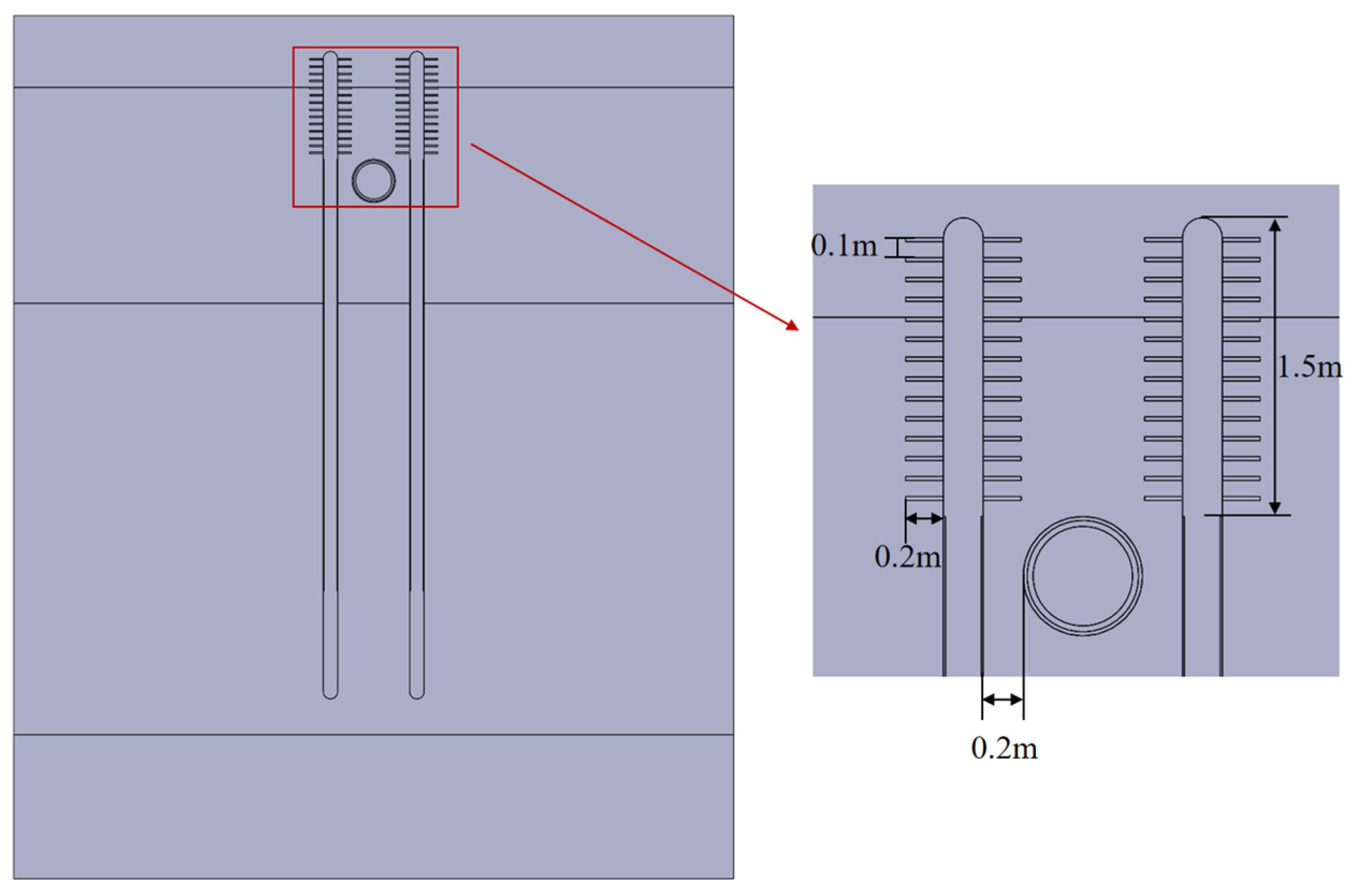
2.1. Geometric Configuration

Based on geological conditions in actual frost heave zones around NGPs, a soil–NGP–heat pipe heat transfer model is developed, as shown in Figure 1. The spatial domain of the geometric model is 10 m × 5 m × 12 m (L × W × H). According to the requirements of the Chinese National Standard GB50028-Code for the design of city gas engineering, the design burial depth of urban gas buried pipelines should ensure that the thickness of the soil covering the top of the pipe (the vertical distance from the original soil layer surface to the top of the pipe) is not less than 0.9 m., In accordance with the actual conditions of certain buried high-pressure pipelines in Beijing, the pipe diameter in the geometric model is specified as DN500, with a burial depth of 2 m, and the heat pipes are inserted into the soil on both sides along the NGP.
To enhance the heat transfer performance of the heat pipes, fins can be added to their condensation section to increase the contact area with the surrounding soil. To further enhance the heat transfer performance of the heat pipe, additional fins were added to the heat pipe to increase the heat transfer contact area between the heat pipe and the soil, as shown in Figure 2. The spacing and number of fins were meticulously calculated to optimize the heat transfer efficiency of the heat pipe.
To avoid the overlap of heating areas around heat pipes with added fins, the fin spacing should be large enough. Meanwhile, the total thermal resistance of fins can be minimized with an optimized fin spacing. The specific calculation formula [17] is as follows:
R f i n = 1 η f i n h f i n A f i n
η f i n = tanh f i n ( n L f i n ) n L f i n
where R f i n , η f i n , A f i n , h f i n , L f i n , and n are the thermal resistance, efficiency, total surface area, convective heat transfer coefficient , height, and form factor of the fins, respectively.
There exists an appropriate fin spacing, which can be specifically calculated as follows [18]:
b = 1 1 h f i n × 2 δ f i n k f i n × tanh f i n ( n L f i n )
n = h f i n P k f i n δ f i n
where b , δ f i n , and k f i n are the spacing, thickness, and thermal conductivity of the fins, respectively.
Based on the above calculation, the optimal fin pitch is determined as 100 mm, and 15 fins are equidistantly installed along the 1.5 m condensation section to maximize the heat transfer process.

2.2. Assumptions

  • The flow velocity of the working fluid liquid film in the heat pipe is typically low, constrained by the pipe wall, and is generally characterized as being in a laminar flow regime.
  • At the macroscopic scale, soil is approximated as an isotropic porous medium with physical properties independent of spatial orientation.
  • The particles in the soil are considered as rigid, with negligible volume changes during the freezing process.
  • Moisture migration in soil occurs at a sufficiently slow rate, which exerts a negligible impact on the heat transfer process.
  • The latent heat effects from ice–water phase change in frozen soil layers are insignificant to the overall heat transfer process.
  • Within heat pipes, vapor flow is relatively independent of liquid film flow, so its effect on the liquid film flow is neglected.
  • Under normal operating conditions, the vapor is typically in a saturated state, and it is assumed that its temperature distribution is uniform.
These basic assumptions appropriately balance model simplification with result reliability, which reduces the computational demands while maintaining physical validity for subsequent frost heave mitigation simulations.

2.3. Heat Transfer Process

The heat transfer process can be categorized into the following three stages.

2.3.1. Heat Transfer Within the Soil

A porous medium heat transfer model is employed to describe heat transfer within the soil. The governing equations are derived from energy conservation principles, incorporating heat exchange between the liquid and solid phases, as well as thermal conduction effects within the porous medium. The equations are as follows.
(a)
Energy Equation:
t [ ( ρ c p ) e f f , s T s ] + x [ ( ρ c p ) e f f , s u x ] + y [ ( ρ c p ) e f f , s u y ] + z [ ( ρ c p ) e f f , s u z ] = x ( k e f f , s T s x ) + y ( k e f f , s T s y ) + z ( k e f f , s T s z )
(b)
Continuity Equation:
ρ w t + ( ρ w u x ) x + ( ρ w u y ) y + ( ρ w u z ) z = 0
(c)
Momentum Equations:
Z-direction:
ρ w ε u z τ + ρ w ε 2 ( u z u z z + u r u z r ) = μ w ε ( 2 u z z 2 + 2 u z r 2 ) p z + S z + S b
R-direction:
ρ w ε u r τ + ρ w ε 2 ( u z u r z + u r u r r ) = μ w ε ( 2 u r z 2 + 2 u r r 2 ) p r + S r
where ( ρ c p ) e f f , s , k e f f , s are the effective volumetric heat capacity and the effective thermal conductivity of the soil, respectively; u x , y , z is the velocity of the pore water in the x , y , and z directions; x , y , z , and r are the axial and radial coordinates; ρ w , μ w are the density and dynamic viscosity of the water, respectively; p is the pressure; ε is the porosity of the soil; S is the source term (values referenced from the literature [19]).
The key parameters include the effective volumetric heat capacity and effective thermal conductivity of the soil, which can be calculated as follows:
( ρ c p ) e f f , s = θ s ρ s C s + ( 1 θ s ) ρ p c p
ρ p = ρ i + H ( T ) × ( ρ w ρ i )
C p = C i + H ( T ) × ( C w C i )
k p = k i + H ( T ) × ( k w k i )
k e f f , s = k s θ s × k p ( 1 θ s )
where θ s is the volume fraction of the soil, c s is the specific heat capacity of dry soil, ρ s is the density of dry soil, c p is the specific heat capacity of water or ice in soil pores, ρ p is the density of water or ice in the pores of the soil, k s is the thermal conductivity of dry soil, c w is the specific heat capacity of water, c i is the specific heat capacity of ice, ρ i is the density of ice, k p is the thermal conductivity of water or ice in soil pores, k w is the thermal conductivity of water, k i is the thermal conductivity of ice, and H ( T ) is the step function with temperature as an independent variable [20].

2.3.2. Heat Transfer Between the Soil and the Heat Pipes

Heat transfer between the heat pipe and the soil relies mainly on convective heat transfer between the air around the heat pipe and the air and moisture in the soil. The formula is as follows:
q = h ¯ Δ T
where q is the heat transfer between heat pipes and soil per unit time, h ¯ is the average convective heat transfer coefficient of a heat pipe, and Δ T is the temperature difference.
The average convective heat transfer coefficient is calculated as follows [21]:
h ¯ = 1 L 0 L h d l = 0.943 ρ l g λ l 3 ( ρ l ρ v ) h f g + 0.68 c p l ( T s a t T w ) μ l L ( T s a t T w )
where L is the effective length of heat transfer from a heat pipe, h is the local convective heat transfer coefficient of a heat pipe, ρ l is the density of the liquid working fluid, ρ v is the density of the steam working fluid, λ l is the thermal conductivity of the liquid film, c p l is the specific heat capacity of the working fluid, T s a t is the saturation temperature of the working fluid, and T w is the wall temperature.
The fundamental heat transfer equation for heat pipes is
Q = m h f g
m = ρ l A l μ l 1 ν
where Q is the capacity of heat transfer, m is the circulating mass flow rate of working fluid, h f g is the latent heat of vaporization of working fluid, A l is the cross-sectional area of the liquid working fluid flow, μ l is the velocity of the liquid working fluid, and v is the volume fraction of the steam working fluid.

2.3.3. Heat Transfer Inside the Heat Pipes

A multiphase flow model was adopted to simulate the heat transfer process inside the heat pipes. The governing equations include the following:
(a)
Continuity Equation:
A p i p e ρ l t + t ( A ρ l u l e t ) = 0
(b)
Equation for Conservation of Momentum:
ρ l u l t = t p l e t 1 2 f D ρ l d p i p e u l u l
(c)
Equation for conservation of energy:
ρ l A p i p e c p l T l t + ρ l A c p l u l e t t T l = t × ( A k l t T l ) + 1 2 f D ρ l A d p i p e u l u l 2 + Q w a l l
where e t is the tangential vector in the direction of the pipe, t is a differential operator in the pipe coordinates, f D is the friction factor that depends on the Reynolds number, d p i p e is the diameter of the heat pipe, p p i p e is the pressure inside the heat pipe, T l is the temperature of the liquid working fluid, and Q w a l l is the rate of heat transfer per unit length through the pipe wall.

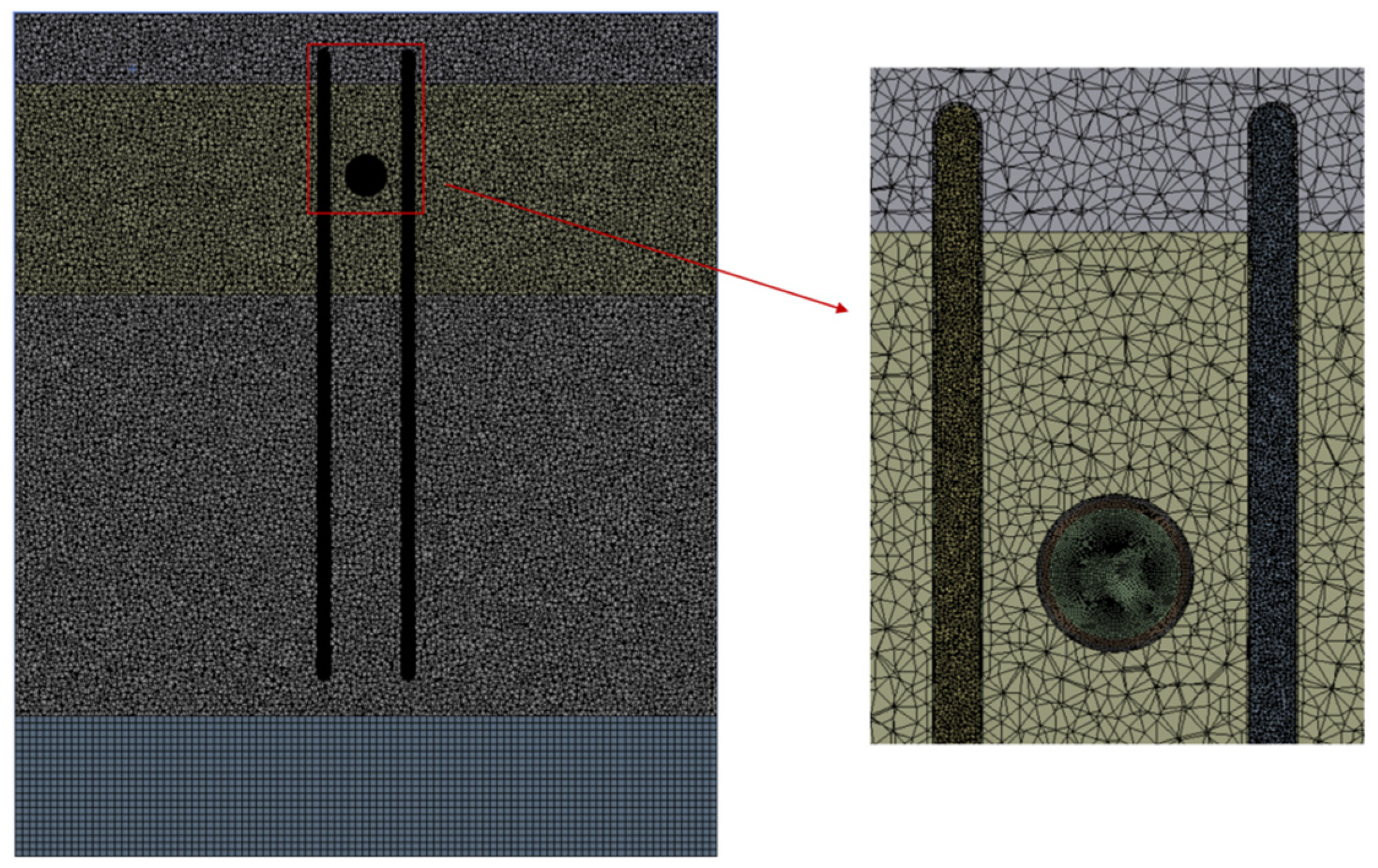
2.4. Mesh Partitioning and Independence Testing

The simulation domain is discretized with a mixture of triangular and quadrilateral cells, as shown in Figure 3. Typically, the refinement of mesh cells will be beneficial for obtaining simulation results that are closer to reality, but it will lead to higher computational costs. To balance the calculation accuracy and cost, grid independence tests were carried out on the established model and the research problem. Soil temperature at 1 m depth along the model centerline is selected as a criterion of mesh quality, as shown in Figure 4, and its temperature convergence diagram is shown in Figure 5.
The results show that when the total mesh count exceeds 5.02 million, temperature variations at the monitoring point are below 0.1% (Figure 6). Further mesh refinement yields no significant computational accuracy improvement but will increase the computational cost. So, the mesh system with 5.02 million cells is optimal for the problem investigated in this work.

3. Results and Discussion

3.1. Setting of the Working Conditions

Taking the Beijing area as a case study, the soil distribution in the frost heave zones surrounding NGPs primarily consists of clayey silt (fill) and clayey sandy silt. The stratigraphic configuration is illustrated in Figure 7, with the specific soil property parameters for different strata listed in Table 1 [22].
By integrating the literature [23] and relevant data from the Chinese Soil Database, it can be concluded that when the soil depth in Beijing reaches 15 m, the soil temperature remains stable and is no longer influenced by fluctuations in ambient air temperature. Based on simulation analysis (as shown in Figure 8), a constant-temperature soil layer at a depth of 10–12 m with a temperature of 10 °C was ultimately selected as the heat source.
The specific parameters of NGPs are shown in Table 2.
The heat pipes employed in the work are made of copper, with the key geometric parameters of the heat pipes being an outer diameter of 200 mm, total length of 9 m (1.5 m in condensation section, 1.5 m in evaporation section, and 6 m in adiabatic section), and thermal conductivity of 20,000 W/(m·K). Ethanol is selected as the working fluid inside the heat pipes, with its physical properties being listed in Table 3.
Natural gas will experience a sudden temperature drop due to the Joule–Thomson effect when passing through the throttling valve at the gas gate station. The coefficient of Joule Thomson coefficient is defined as
μ J T = T m T b P m P b
where μ J T is the coefficient of Joule–Thomson coefficient, T m is the temperature of the gas before passing through the throttle valve, T b is the temperature of the gas after passing through the throttle valve, P m is the pressure of the gas before passing through the throttle valve, P b is the pressure of the gas after passing through the throttle valve.
According to the gas pressure difference and ambient temperature before and after the throttle valve, μ J T can be determined as 3.713 K/MPa from the check table [26]. Substituting into Equation (21), the post-throttling gas temperature is calculated as −22 °C.
In this work, the influences and mitigation effects of heat pipes on the seasonal soil frost heave problem are evaluated from the following five perspectives:
To analyze the mitigation effects of the distance between pipeline and heat pipe (DPHP) on the soil frost heave problem, eight simulation scenarios with DPHP values from 50 mm to 400 mm at 50 mm intervals were conducted.
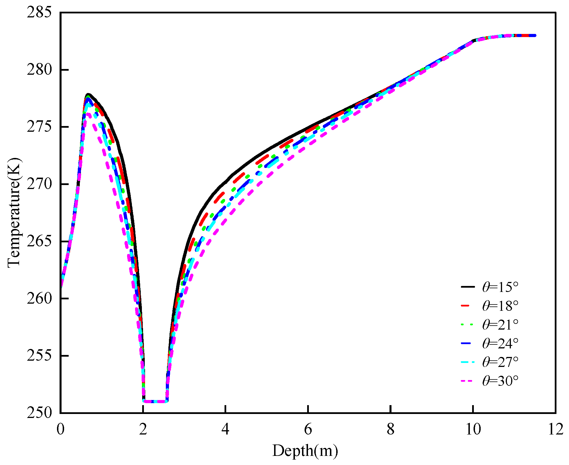
  • To see the mitigation effects of the angle between the central axis of the heat pipe and the model centerline (AHPAMC) on the soil frost heave problem, six simulation cases with the AHPAMC ranging from 15° to 30° at 3° increments were conducted.
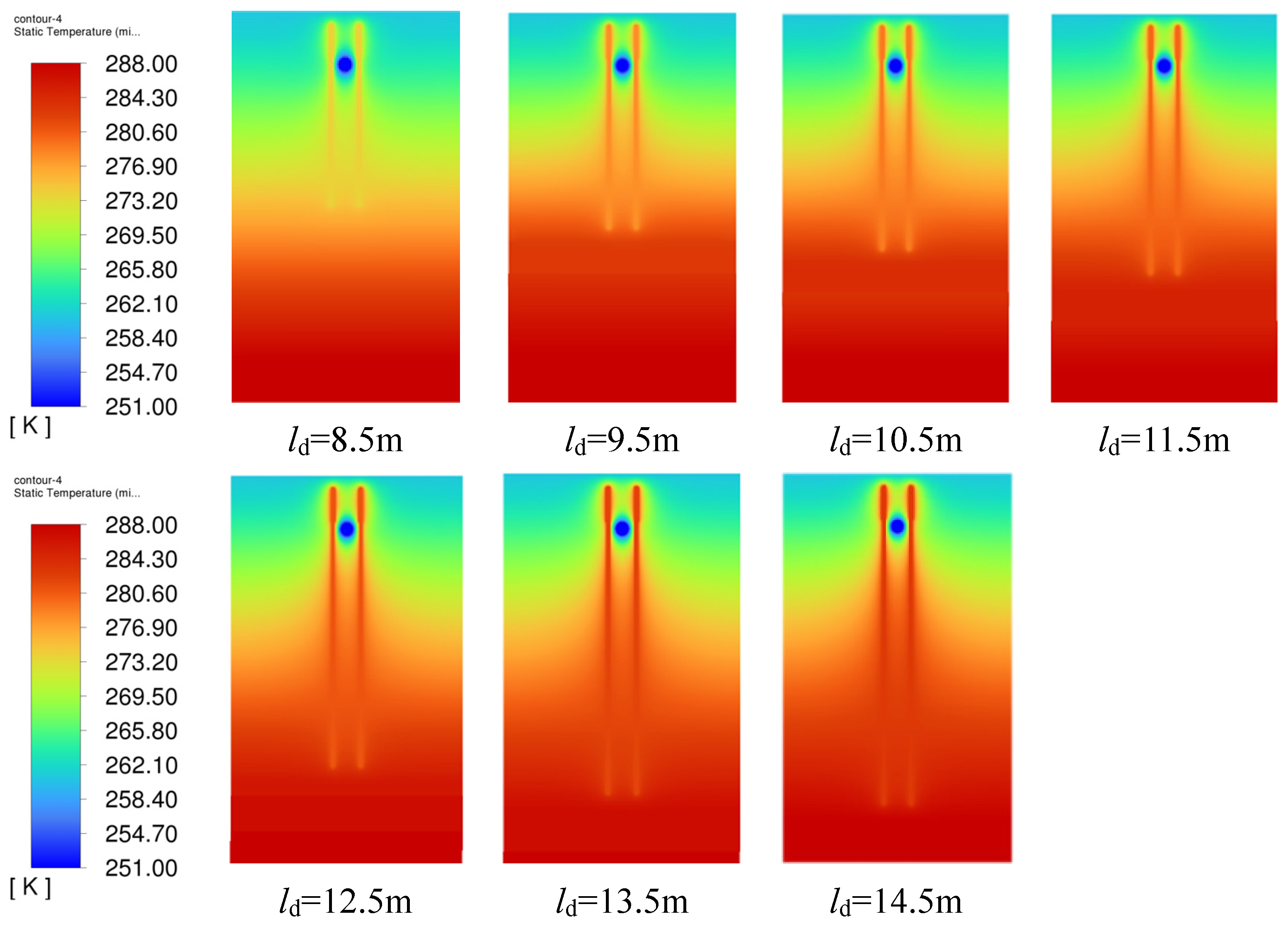
  • To explore the mitigation effects of heat source temperatures caused by different heat pipe insertion depths (HPIDs) on the soil frost heave problem, seven simulation cases with HPID changing from 9 m to 15 m at 1 m intervals were studied.
  • To evaluate the effects of heat pipe thermal conductivity (HPTC) on the soil frost expansion problem, five scenarios were simulated with HPTC values starting at 2500 W/(m·K) and increasing by factors of two, four, eight, and sixteen successively.
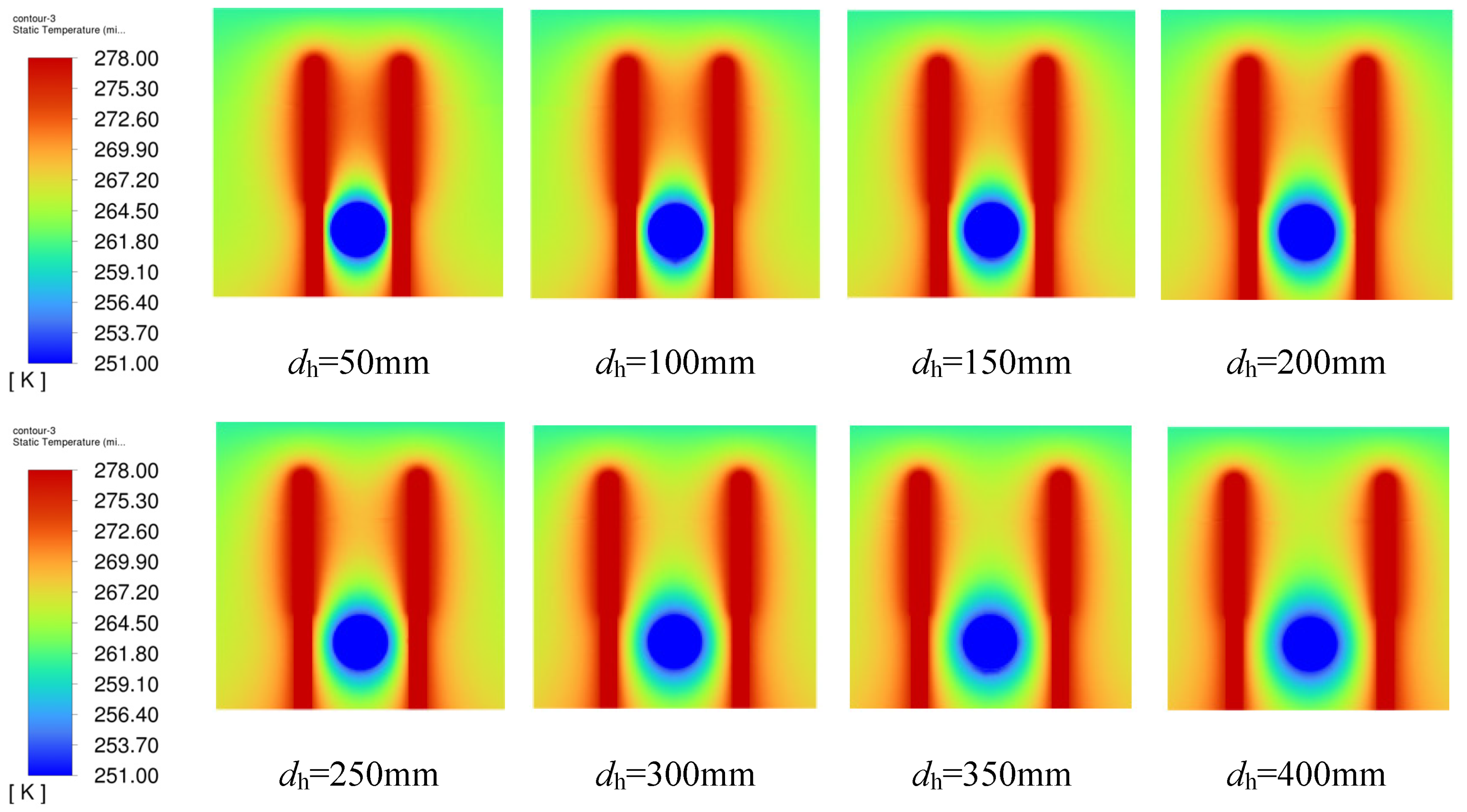
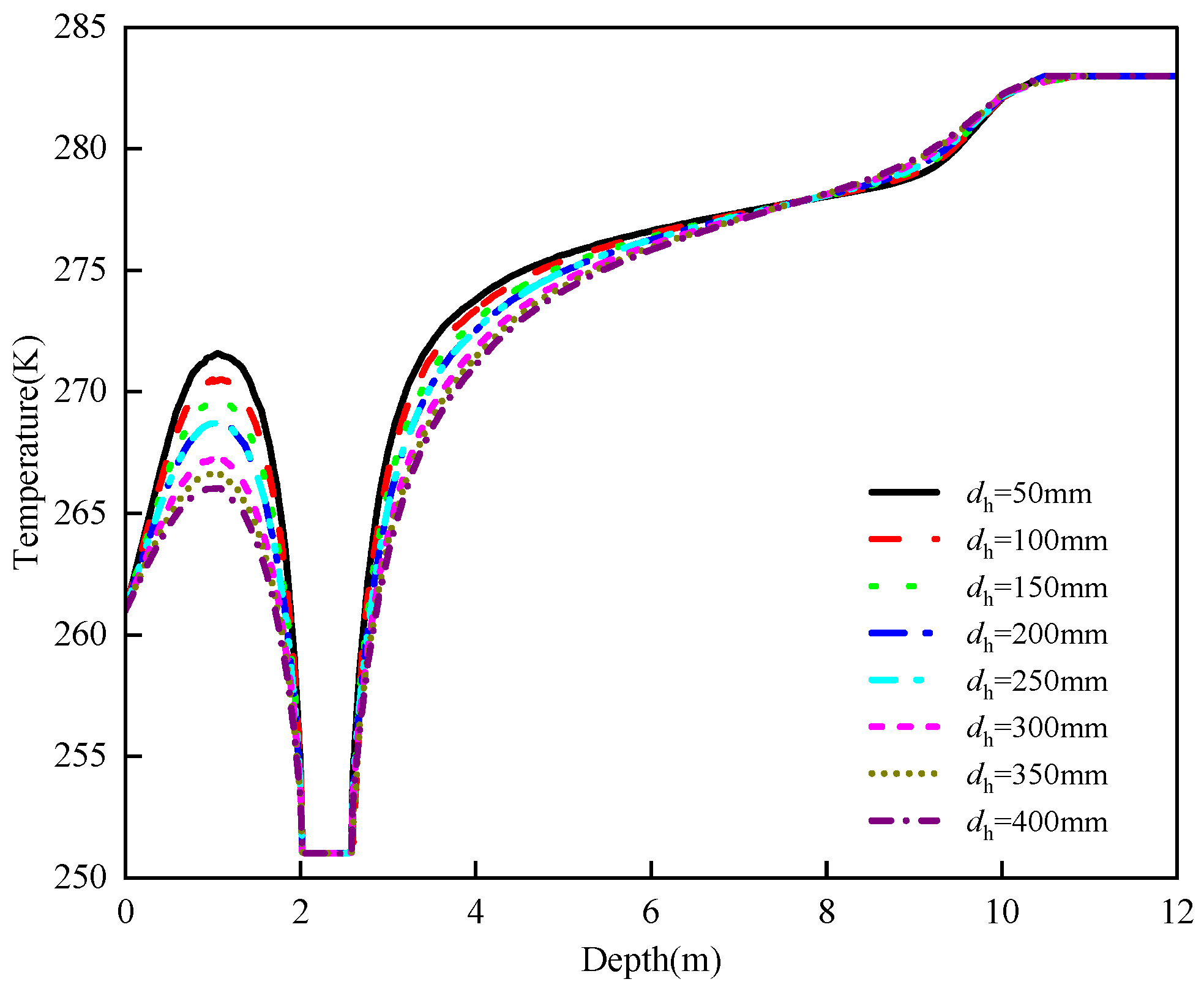
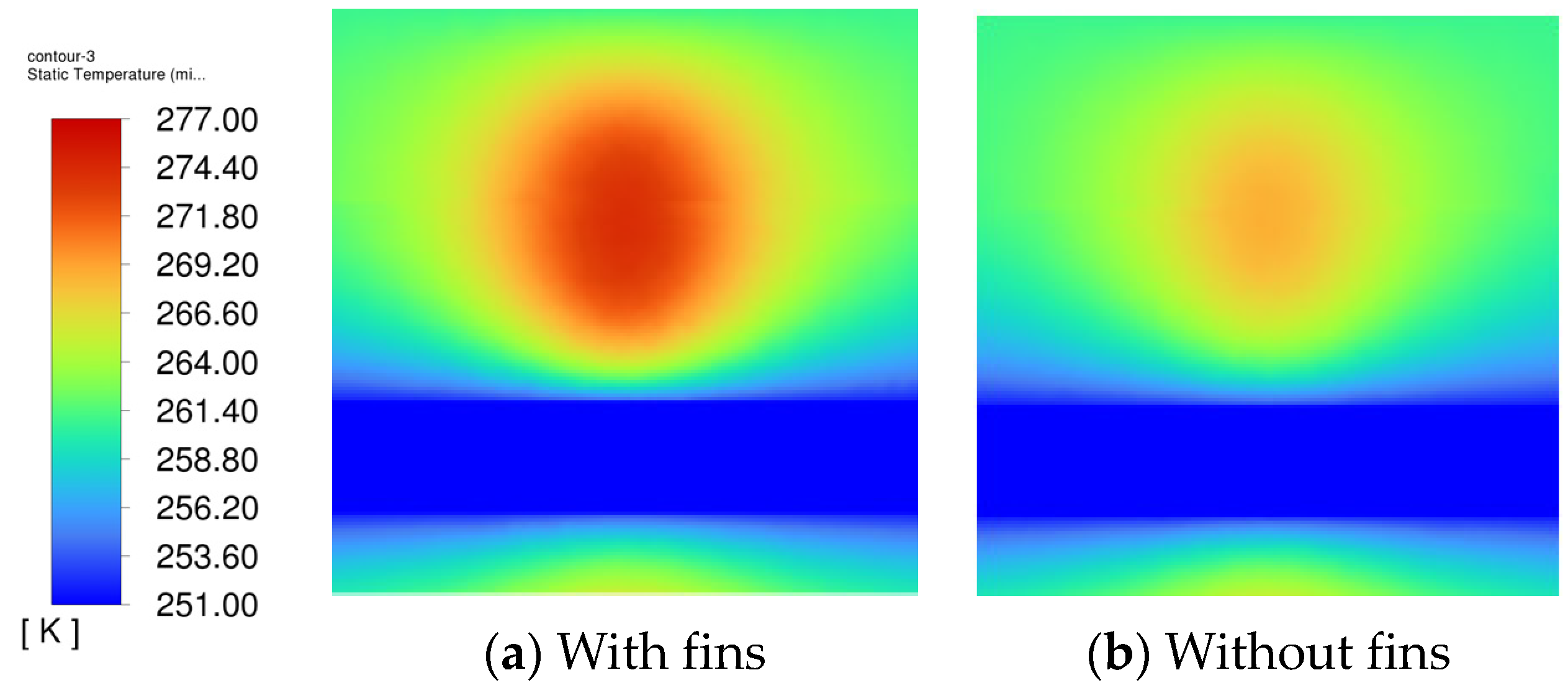
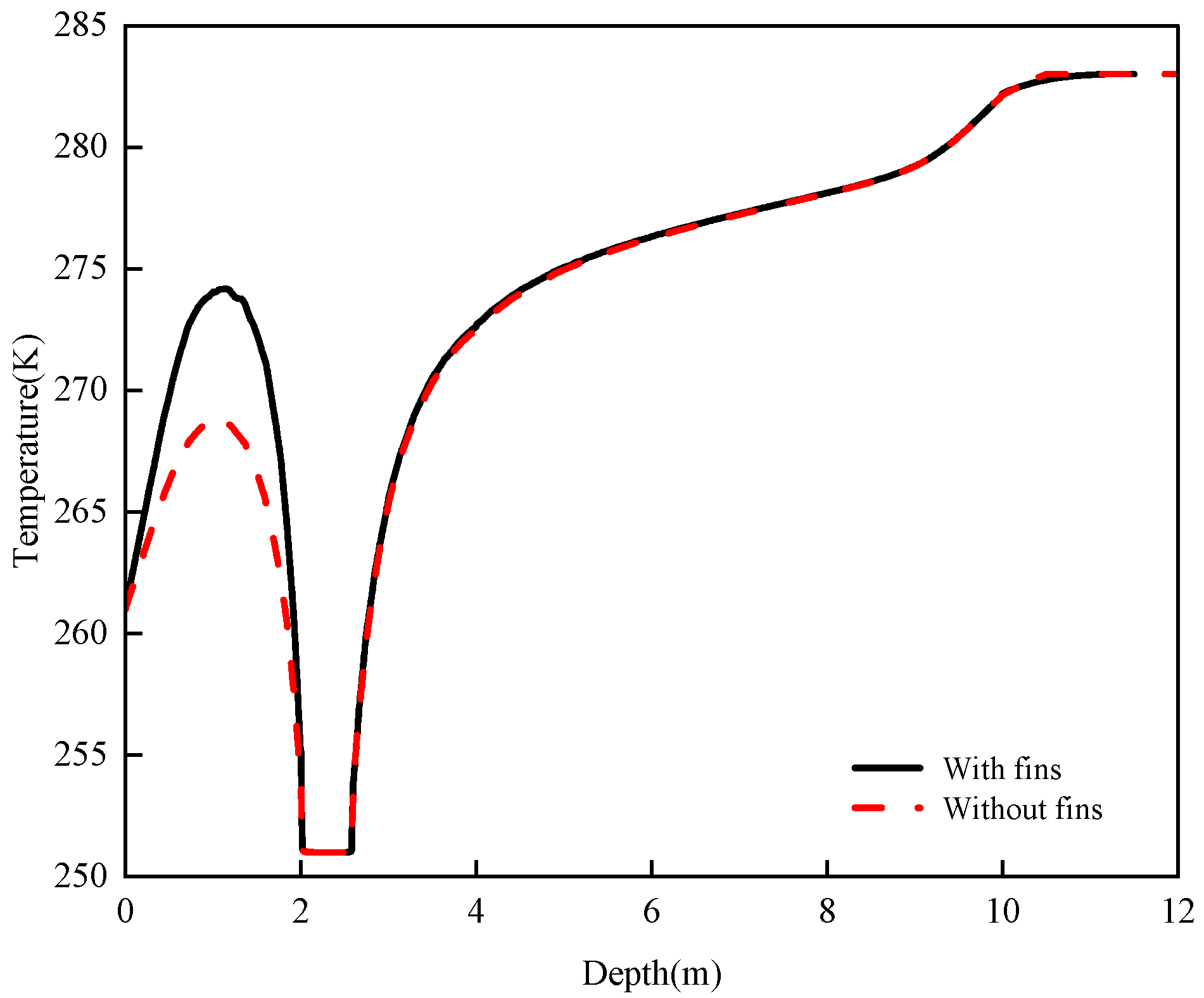
  • To analyze the mitigation effects of extra added fins on the soil frost heave problem, a typical scenario with a DPHP of 200 mm was simulated, where extra fins were added in the condensation section of the heat pipes.

3.2. Effects of Heat Pipe Positioning and Parameters on Soil Temperature Distribution

3.2.1. Effect of Thermal Conductivity

Figure 9 illustrates the temperature distribution along the model centerline under various HPTC conditions. From the single curve with HPTC of 2500 W/(m·K), it can be seen that in the depth range of 0–1 m, the soil temperature shows an increasing trend, which is due to the release of heat from the condensing section of the heat pipe, which raises the soil temperature. In the 1–2 m depth range, the soil temperature starts to decrease, which is due to the high speed transportation of low temperature gas in the NGP, which releases cold. It can be seen that a local temperature peak appears in the soil above NGPs at a depth of 1 m. Beyond 2.5 m depth, the soil temperature gradually increases with depth but at a diminishing rate. Thereafter, the temperature rise accelerates significantly beyond 9 m depth, and then stabilizes near the thermostatic layer at 10 m depth. Further comparison demonstrates that the heat transfer capacity of heat pipes can be enhanced with the increase in HPTC. The local soil temperature peak above the NGP (around 1 m depth) rises from 261.9 K to 269.3 K when HPTC is increased from 2500 W/(m·K) to 40,000 W/(m·K). However, the differences in local temperature peak are only increasing by 0.6 K when HPTC is 20,000 W/(m·K) and 40,000 W/(m·K), indicating that the sensitivity of soil temperature to HPTC decreases when it is already at a high level. That is to say, the further increase in HPTC has a reduced enhancement on improving the heat transfer process. Thus, it is crucial to appropriately select HPTC for optimizing soil temperature fields around NGPs and thus to mitigate frost heave problems with an affordable requirement of heat pipes.
Considering the manufacturing costs and technical challenges in achieving ultra-high conductivity, heat pipes with thermal conductivity of 20,000 W/(m·K) were selected for the subsequent investigations.

3.2.2. Effect of Heat Pipe Insertion Depth

Figure 10 shows the temperature distribution contours under different HPID (ld) conditions. When ld is 8.5 m, the relatively low soil temperature at the evaporation section of heat pipes limits the heat exchange efficiency with the surrounding soil, so that the soil temperature around the NGP is not significantly elevated. With the increase of HPID, the soil temperature in the localized area above the NGP increases.
The optimal heating state of heat pipes occurs when ld is increased to 14.5 m, where the soil temperature at 1 m depth is significantly higher than that when ld is only 8.5 m. It can be found from Figure 10 that when ld is larger than 9.5 m, heat pipes can effectively elevate the soil temperatures around the NGP, thus guaranteeing the soil temperature stability here and reducing the soil freezing potential.
Figure 11 plots the soil temperature distribution along the model centerline under various HPID conditions. It is revealed that with the increase of HPID, the local peak soil temperature above the NGP shows an upward trend, rising from 266.7 K to 271.4 K when ld is increased from 8.5 m to 14.5 m. When ld is increased to 14.5 m, the local peak soil temperature above the NGP is 12.4 K higher than that without heat pipes. Comparatively, when ld is only 8.5 m, the local peak soil temperature at the same location is only 4.7 K higher than that without heat pipes. With the increase of HPID, the bottom of the heat pipe gets deeper, and the soil temperature at the evaporation section is higher, so more heat can be absorbed by the evaporation section. So, the elevation of soil temperature above NPG is higher when HPID is increased. However, the increased amplitude in the local peak soil temperature gradually decreases when HPID is continuously increased. This indicates that there exist threshold effects of HPID on soil temperature improvement, when HPID is increased to a certain value, its further increase in depth tends to have a weak effect on soil temperature at a depth of 1 m above the NGP. Considering the rising construction complexity with the increase of HPID, ld of 9.5 m is selected as the optimal insertion depth of heat pipes in this work. With this insertion depth, the relatively high soil temperature at the bottom of the heat pipes can be effectively utilized to enhance the heat transfer characteristics of the heat pipe, to achieve acceptable regulation of soil temperature above the NGP. Meanwhile, the excessive increase in cost and construction difficulty due to larger insertion depth can be avoided.

3.2.3. Effect of Heat Pipe Insertion Depth

Figure 12 presents the temperature distribution contours under different DPHP (dh) conditions. When dh is set as 200 mm, the thermal influence zones of heat pipes on the two sides of the NGP start to overlap. When dh is reduced to 50 mm, the heating effect is the best, and the local peak soil temperature at 1 m depth is increased by 12.6 K compared with that without a heat pipe.
Figure 13 shows the soil temperature distribution along the model centerline under various DPHP conditions, where the local peak soil temperature above the NGP increases significantly with the decrease of the DPHP. When the DPHP is decreased from 400 mm to 50 mm, the local peak soil temperature above the NGP increases from 266.0 K to 271.6 K. The reason is that when the DPHP is decreased, the heat transferred by heat pipes is more concentrated in a small region above the NGP; thus, a more pronounced temperature increase here can be witnessed. However, although the heating effect of heat pipes on the soil above the NGP is most significant when dh is 50 mm, heat absorption at the bottom of the heat pipes is too concentrated. Since the simulation domain is limited in this work, the heat of the thermostatic layer is difficult to fully make up for the missing heat, which tends to form a large temperature gradient near the heat pipe. Furthermore, in the practical application process, this will lead to a significant temperature difference between the soil near and far away from the heat pipes, thus resulting in a series of potential problems, such as non-uniformity of soil thermal stress, reduction of the heat transfer efficiency of heat pipes, and eventually, the possible performance degradation of heat pipes in long-term operation.
With comprehensive consideration of the effects of DPHP on soil temperature distribution, heat transfer efficiency of heat pipe, and the temperature recovery characteristics of the thermostatic layer, dh of 200 mm is more reasonable for the investigated condition. With this distance, the heating effect of heat pipes to the soil can be ensured, with the local peak soil temperature above the NGP reaching 268.7 K. Meanwhile, the problem of excessively concentrated heat absorption at the bottom of the heat pipe can be avoided, to ensure the long-term stable operation of the heat pipe system.

3.2.4. Effect of the Angle Between the Central Axis of the Heat Pipe and the Model Centerline

Figure 14 plots the local soil temperature distribution contours under different AHPAMC (θ) conditions. When θ is set as 15°, an obvious high-temperature zone is formed at the ends of heat pipes and around the NGP, indicating that the heat transported from the bottom thermostatic layer is mainly concentrated near the heat pipes and NGP. When θ is increased to 30°, the heating region is no longer confined to a specific small area. This indicates that with the increase in the AHPAMC, the heating area of heat pipes expands, and the high-temperature zone is not concentrated in a narrow area.
Figure 15 plots the soil temperature distribution along the model centerline under different DPHP conditions. It is clear that a local peak soil temperature appears above the NGP at a depth of 0.6 m. Beyond 2.5 m depth, the soil temperature gradually increases as the soil depth continues to increase, and then stabilizes until it reaches the thermostatic temperature at 10 m depth.
With the increase in θ, the increased amplitude of soil temperature above the NGP shows a decreasing trend. Beyond 2 m depth, the variation trend of the temperature curve under different conditions remained consistent, although slight differences still exist in the temperature recovery rates. When θ is 15°, the local peak soil temperature above the NGP is 276.7 K, which is 17.7 K higher than that without heat pipes. Meanwhile, compared with the condition with θ of 30°, the local peak soil temperature is 1.7 K higher, and the soil temperature at 1 m depth is 3.2 K higher.
It can be concluded from the above analysis that the smaller the AHPAMC is, the more concentrated the heat transferred by heat pipes is, and the stronger its ability to alleviate the soil frost heave problem above the NGP. So, for the investigated scenarios, θ of 15° is recommended.

3.2.5. Effect of Adding Fins to the Heat Pipe

Figure 16 shows the local soil temperature distribution contours in the longitudinal section of the model centerline (width direction of the simulation domain). The red zone represents the concentrated heating area by the heat pipes, and the blue striped zone represents the low-temperature flow area inside the NGP. Due to the high-speed movement of natural gas inside the NGP and the strong thermal inertia of soil, the natural gas temperature change in the NGP is small, which almost remains at 251 K. It can be observed that when the heat transfer area is enlarged by the addition of fins, the heat transfer process is significantly promoted, and the soil temperature above the NGP is improved to a greater extent.
The soil temperature along the model central line is further quantitatively plotted in Figure 17. At a depth of 1 m, the soil temperature above the NGP reaches 274.2 K after adding fins, which is 15.2 K higher than that without a heat pipe and is also 5.5 K higher than that without adding fins. These results demonstrate that the addition of fins can remarkably improve the heat transfer efficiency of heat pipes, thus increasing the soil temperature level above the NGP, which is of great significance in alleviating the soil from frost heave problems.

4. Conclusions

A method of using heat pipes to transfer shallow geothermal energy to mitigate the frost heave problem in seasonal frozen soil around NGPs was proposed, and a soil–NGP–heat pipe heat transfer model was developed to analyze the effects of various parameters on the heat transfer performance and frost heave mitigation effects. Key findings are as follows.
The minimum distance (ld) between the wall of the heat pipe and the gas pipe wall, the angle (θ) formed between the central axis of the heat pipe and the central axis of the model, as well as the depth (dh) of the heat pipe’s insertion into the ground, all significantly influence the soil temperature distribution and the effectiveness of frost heave mitigation. When ld is 200 mm or θ is 15°, the heating effect of heat pipes is the most significant, which elevates the local peak soil temperature above the NGP by 9.7 K and 17.7 K, respectively, when compared with that without heat pipes.
The thermal conductivity of heat pipes is vital for soil frost heave mitigation. Simulation analyses revealed that the heat transfer capacity of heat pipes increases as the thermal conductance coefficient rises. However, when the thermal conductance coefficient reaches 20,000 W/(m·K), the enhancement in heat transfer efficiency begins to plateau.
Adding fins to the heat pipe can significantly enhance its heat transfer efficiency. When fins are incorporated, the local peak temperature of the soil above the NGP reaches 274.2 K, which is 5.5 K higher than that without fins.
These findings have demonstrated that the application of heat pipes in frost-heaving soil surrounding NGPs can effectively mitigate soil frost heave. Additionally, the geometric arrangement critically determines performance. At optimal values (ld = 200 mm, dh = 9.5 m, adding fins), peak soil temperature rises by 15.2 K, and the soil frost heave displacement is 36% higher compared to the condition with heat pipes. Nevertheless, their specific implementation must be carefully analyzed in conjunction with site-specific conditions to achieve optimal heat transfer performance.

Author Contributions

Conceptualization, P.X.; methodology, P.X. and Y.B.; validation, P.X. and Y.B.; writing—original draft preparation, P.X. and Y.B.; writing—review and editing, P.X.; visualization, P.X. and Y.B. All authors have read and agreed to the published version of the manuscript.

Funding

This research received no external funding.

Data Availability Statement

Data will be made available on request.

Conflicts of Interest

Yuyang Bai was employed by the Beijing Institute of Public Utilities Science Co., Ltd. The remaining author declares that the research was conducted in the absence of any commercial or financial relationships that could be construed as a potential conflict of interest.

References

  1. Marić, I. The Joule–Thomson effect in natural gas flow-rate measurements. Flow Meas. Instrum. 2005, 16, 387–395. [Google Scholar] [CrossRef]
  2. Deng, F.; Lu, J.; Wan, X.; Liu, B.; Zhang, B.; Fu, H. Mitigating frost heave of a soil stabilized with sisal fiber exposed to freeze-thaw cycles. Geotext. Geomembr. 2025, 53, 394–404. [Google Scholar] [CrossRef]
  3. Tai, B.; Wu, Q.; Yue, Z.; Xu, H. Ground temperature and deformation characteristics of anti-freeze-thaw embankments in permafrost and seasonal frozen ground regions of China. Cold Reg. Sci. Technol. 2021, 189, 103331. [Google Scholar] [CrossRef]
  4. Zhang, W.; Zhang, D.; Guo, L.; Dong, T.; Wang, J.; Wang, J.; Yu, Q. Experimental study on heating performance of a solar circulating heated embankment system for the treatment of frost heave disease in seasonally frozen regions. Sol. Energy 2022, 248, 41–50. [Google Scholar] [CrossRef]
  5. Li, X.; Wu, Q.; Jin, H.; Shi, R.; Wu, G.; Cao, Y. Numerical evaluation of the effectiveness of frost heave mitigation strategies for chilled arctic gas pipelines. Res. Cold Arid Reg. 2022, 14, 338–345. [Google Scholar] [CrossRef]
  6. Chen, J.; Huang, W.; Cen, J.; Li, Z.; Li, F.; Li, A.; Sun, H.; Lin, W.; Ma, Q.; Jiang, F. Operational characteristics of the super-long gravity heat pipe for geothermal energy exploitation. Appl. Therm. Eng. 2024, 236, 121530. [Google Scholar] [CrossRef]
  7. Huang, W.; Cen, J.; Chen, J.; Cao, W.; Li, Z.; Li, F.; Jiang, F. Heat extraction from hot dry rock by super-long gravity heat pipe: A field test. Energy 2022, 247, 123492. [Google Scholar] [CrossRef]
  8. Jose, J.; Kumar Hotta, T. A comprehensive review of heat pipe: Its types, incorporation techniques, methods of analysis and applications. Therm. Sci. Eng. Prog. 2023, 42, 101860. [Google Scholar] [CrossRef]
  9. Liu, W.; Liu, X.; Chow, T.; Hao, Y.; Lau, W.; Pan, C. Thermal characteristics of heat-pipe-ring embedded building façades as both building-integrated and building-attached solar collectors. Case Stud. Therm. Eng. 2024, 60, 104621. [Google Scholar] [CrossRef]
  10. Alhuyi Nazari, M.; Kumar, R.; Mukhtar, A.; Yasir, A.S.H.M.; Ahmadi, M.H.; Al-Bahrani, M. Geothermal energy for preheating applications: A comprehensive review. J. Cent. South Univ. 2023, 30, 3519–3537. [Google Scholar] [CrossRef]
  11. Alsagri, A.S.; Chiasson, A.; Shahzad, M.W. Geothermal Energy Technologies for Cooling and Refrigeration Systems: An Overview. Arab. J. Sci. Eng. 2022, 47, 7859–7889. [Google Scholar] [CrossRef]
  12. Wu, C.; Sun, Z.; Pan, Y. Theoretic study on the technology of applying heat pipe to solving frost heaving. Chin. J. Geotech. Eng. 2002, 24, 347–350. [Google Scholar]
  13. Li, Z.; Jiang, R.; Tang, A.; Zhu, R. Heat-water-stress Coupling Model for Saturated Frozen Soil under Different Stress Levels. KSCE J. Civ. Eng. 2024, 28, 4897–4910. [Google Scholar] [CrossRef]
  14. Hu, T.; Zhao, L.; Wang, T.; Yue, Z.; Yuan, Y.; Zhang, Y. Geothermal heat pump solutions for frost heave control in railway subgrades. Geothermics 2025, 127, 103244. [Google Scholar] [CrossRef]
  15. Deng, G.; Yang, J.; Ma, X.; Kang, N.; He, J.; Li, J. Analysis of temperature response and thermal performance of hybrid gravity heat pipes for winter soil warming of grapevine root systems. Trans. Chin. Soc. Agric. Eng. 2025, 41, 230–237. [Google Scholar]
  16. Sanner, B. Shallow geothermal energy—History, development, current status, and future prospects. In Proceedings of the European Geothermal Congress 2016, Strasbourg, France, 19–24 September 2016. [Google Scholar]
  17. Yin, J.; Xing, Y.; Wang, S.; Hou, X.; Wang, Z.; Xu, Z. Temperature Response Calculation Model of Energy Storage Finned Tube Based on Thermal Network. J. Aerosp. Power 2023, 38, 2395–2406. [Google Scholar]
  18. Gan, B. Experimental study on the effect of fin spacing on the heat transfer and flow resistance of plate fin-and-tube heat exchangers. Energy Res. Inf. 2018, 34, 97–101. [Google Scholar]
  19. Yang, Q.; Yang, T.; Yang, Y.; Shen, J. Numerical and experimental investigations on the effect of skeleton shapes and heat transfer directions on water freezing in porous media. Int. J. Heat Mass Transf. 2025, 236, 126392. [Google Scholar] [CrossRef]
  20. Wang, G.; Lin, C.; Zhu, L.; Feng, D.-C.; Xin, Y.-Y.; Zhang, F. Performance analyses of two-phase closed thermosyphons for road embankments in the high-latitude permafrost regions. J. Mt. Sci. 2023, 20, 3138–3153. [Google Scholar] [CrossRef]
  21. Malitha, C.; Rajapaksha, M.; Shankar, V.; Senadheera, S. Improved empirical convection heat transfer coefficient model to predict flexible pavement layer temperatures. Constr. Build. Mater. 2024, 411, 134206. [Google Scholar]
  22. Zou, M.; Wang, Y.; Liu, Y. The present status and problems of the research on Beijing urban green space soil. Soil Fertil. Sci. China 2012, 3, 1–6. [Google Scholar]
  23. Wang, W.; Wang, G.; Zhu, X.; Liu, Z. Characteristics and potential of shallow geothermal resources in provincial capital cities of China. Geol. China 2017, 44, 1062–1073. [Google Scholar]
  24. Zhang, X.; Wang, Z.; Ding, S.; Wang, Z.; Xie, H. Fabrication of Flame-Retardant Ammonium Polyphosphate Modified Phytic Acid-Based Rigid Polyurethane Foam with Enhanced Mechanical Properties. Polymers 2024, 16, 2229. [Google Scholar] [CrossRef] [PubMed]
  25. Engineers, R.A. ASHRAE handbook: Fundamentals. In Ashrae Handbook Fundamentals; ASHRAE (American Society of Heating, Refrigerating and Air-Conditioning Engineers): Atlanta, GA, USA, 2021. [Google Scholar]
  26. Ernst, G.; Keil, B.; Wirbser, H.; Jaeschke, M. Flow-calorimetric results for the massic heat capacitycpand the Joule–Thomson coefficient of CH4, of (0.85CH4 + 0.15C2H6), and of a mixture similar to natural gas. J. Chem. Thermodyn. 2001, 33, 601–613. [Google Scholar] [CrossRef]
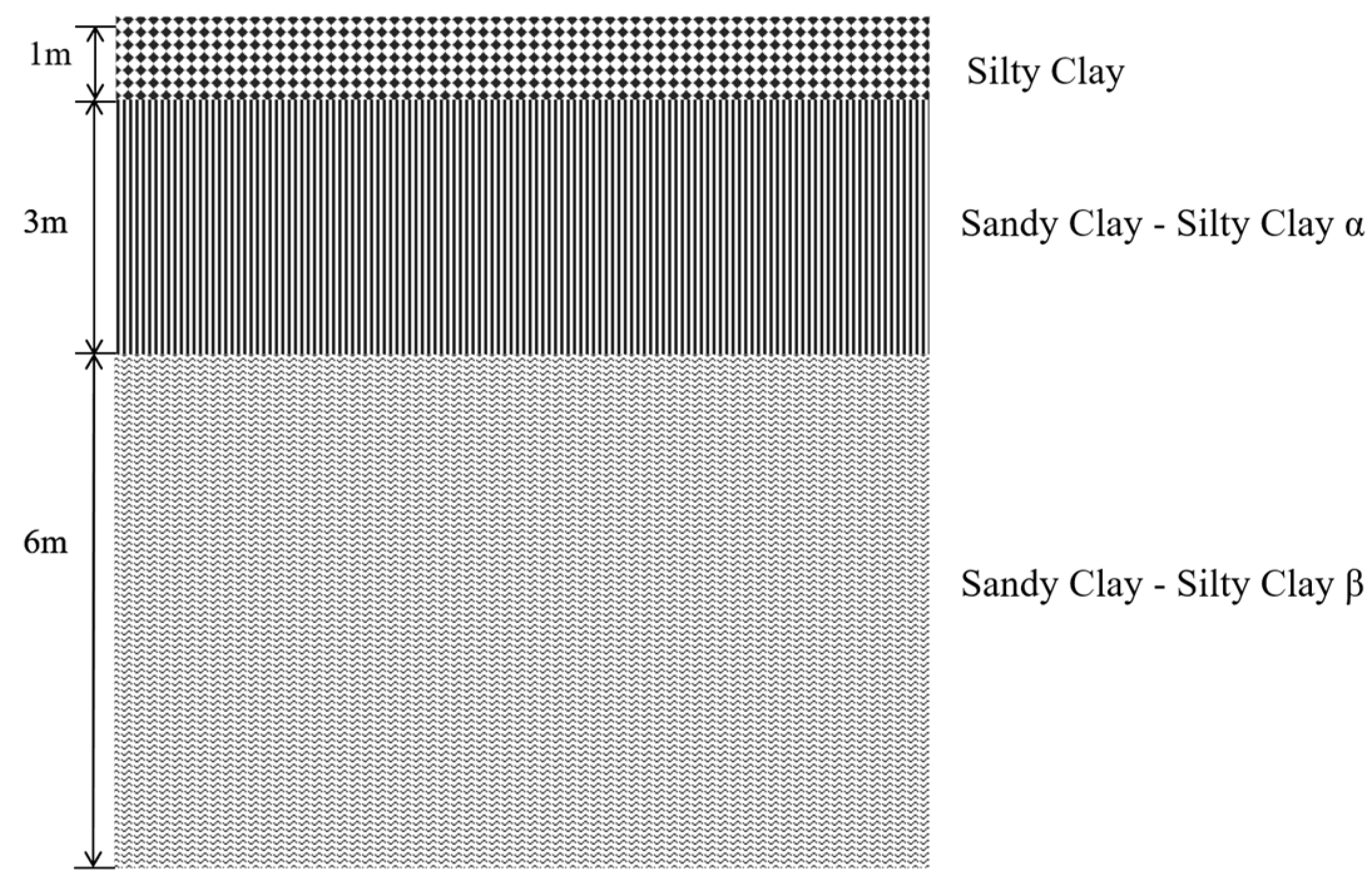
Figure 1. Soil–NGP–heat pipe heat transfer model. (I. silty clay; II. sandy clay–silty clay α; III. sandy clay–silty clay β).
Energies 18 03316 g001
Figure 2. Simplified model of heat pipes with added fins.
Energies 18 03316 g002
Figure 3. Meshing view.
Energies 18 03316 g003
Figure 4. Schematic diagram of key monitoring points for mesh quality comparison.
Energies 18 03316 g004
Figure 5. Convergence plot of temperatures at key monitoring points.
Energies 18 03316 g005
Figure 6. Mesh independence test.
Energies 18 03316 g006
Figure 7. Selected soil stratigraphic characteristics [19,20].
Energies 18 03316 g007
Figure 8. Temperature distribution map of the frost heave area of the soil around the gas pipeline at a depth of 0–15 m.
Energies 18 03316 g008
Figure 9. Soil temperature distribution at the model centerline under various HPTC conditions.
Energies 18 03316 g009
Figure 10. Temperature contour under various HPID conditions.
Energies 18 03316 g010
Figure 11. Soil temperature distribution at the model centerline under various HPID conditions.
Energies 18 03316 g011
Figure 12. Local temperature contour under various DPHP conditions.
Energies 18 03316 g012
Figure 13. Soil temperature distribution at the model centerline under various DPHP conditions.
Energies 18 03316 g013
Figure 14. Local temperature contour under various AHPAMC conditions.
Energies 18 03316 g014
Figure 15. Soil temperature distribution at the model centerline under various AHPAMC conditions.
Energies 18 03316 g015
Figure 16. Local temperature contour under whether or not to add fins conditions.
Energies 18 03316 g016
Figure 17. Soil temperature distribution at the model centerline with or without fin conditions.
Energies 18 03316 g017
Table 1. Soil characteristic parameter [22].
Soil TypesDensity (kg/m3)Specific Heat Capacity (J/(kg·K))Thermal Conductivity (W/(m·K))Porosity
Silty Clay195014601.6950.43
Sandy Clay–Silty Clay α197013701.6270.68
Sandy Clay–Silty Clay β197013701.6270.73
Table 2. Specific parameters of gas pipelines [24].
NameMaterialDensity (kg/m3)Specific Heat Capacity (J/kg·K)Thermal Conductivity (W/m·K)Thickness (mm)
Gas pipelineCarbon steel78504805216
Insulation layerPolyurethane foam451.720.0228
Table 3. Physical properties of ethanol [25].
Specific Heat Capacity (kJ/kg·K)Boiling Point (K)Freezing Point (K)Latent Heat of Vaporization (kJ/kg)Viscosity (mPa·s)
2.42280.8 1159.18310.594
1 The data are taken at 90% of the standard atmospheric pressure in a vacuum.
Disclaimer/Publisher’s Note: The statements, opinions and data contained in all publications are solely those of the individual author(s) and contributor(s) and not of MDPI and/or the editor(s). MDPI and/or the editor(s) disclaim responsibility for any injury to people or property resulting from any ideas, methods, instructions or products referred to in the content.

