Article

Study on Dispersion of Impulse Discharge in SF6 and Eco-Friendly Insulating Gas C4F7N/CO2

by
Tianran Zhang
1,
Fang He
1,*,
Lubin Chang
1 and
Wenjun Zhou
2
1
School of Electrical Engineering, Naval University of Engineering, Wuhan 430030, China
2
School of Electrical Engineering and Automation, Wuhan University, Wuhan 430072, China
*
Author to whom correspondence should be addressed.
Energies 2025, 18(13), 3228; https://doi.org/10.3390/en18133228
Submission received: 27 April 2025 / Revised: 23 May 2025 / Accepted: 18 June 2025 / Published: 20 June 2025

Abstract

:
In recent years, C4F7N/CO2 gas has been widely studied as an eco-friendly alternative to SF6, which is commonly used in electrical equipment. To ensure electrical equipment reliability, the dispersion of impulse discharge voltage of insulated gas is generally required to be less than 3%. However, experimental results indicate that under fault conditions, such as sudden pressure changes or electric field distortion, the discharge dispersion of both C4F7N/CO2 and SF6 often exceeds 3%. This paper investigates the impact of pressure and electric field nonuniformity on the dispersion of impulse discharge voltage for conventional and eco-friendly insulating gases under varying degrees of electric field nonuniformity. Experiments reveal that under identical conditions, the 9%C4F7N/91%CO2 mixture exhibits lower impulse discharge voltage dispersion compared with SF6. As pressure increases, the dispersion decreases for both gases. Conversely, dispersion increases with higher electric field nonuniformity, and the 9%C4F7N/91%CO2 mixture demonstrates greater sensitivity to electric field nonuniformity than SF6. In practical applications, electrical equipment typically operates under slightly nonuniform electric fields and high pressure, meeting dispersion requirements. However, if electric field distortion causes the nonuniformity factor (f) to exceed 2.4 or if pressure drops below 0.3 MPa then dispersion increases significantly, reducing the reliability of insulation performance data.

1. Introduction

SF6 is extensively used in electrical insulation due to its excellent insulating and arc-quenching properties [1]. However, SF6 has a global warming potential (GWP) 23,900 times higher than CO2 and an atmospheric lifetime of approximately 3200 years. It was listed as a restricted greenhouse gas in the 1997 Kyoto Protocol [2], accelerating global warming. For example, the Sutong 1000 kV GIL project in China uses 19 tons of SF6 per kilometer, totaling 665 tons [3]. Assuming an annual leakage rate of 0.1%, 0.665 tons of SF6 would leak annually, equivalent to 16,000 tons of CO2 emissions. To mitigate SF6 usage, eco-friendly alternatives with comparable physicochemical properties are urgently needed.
C4F7N has emerged as a promising SF6 substitute, offering twice the insulation strength of pure SF6. According to Yannick Kieffel et al., C4F7N has a GWP of 2100 and zero ozone depletion potential [4]. Commercialized by 3M (Saint Paul, MN, USA), its high cost (60 times that of SF6) and high liquefaction temperature (−4.7 °C at 0.1 MPa) limit its standalone use. Recent research focuses on C4F7N/CO2 mixtures to balance insulation performance, lower liquefaction temperatures, and reduce costs. Alstom (2014 CIGRE, Mumbai, Maharashtra) and GE (2015 CIRED, Boston, MA, USA) proposed C4F7N/CO2 mixtures for gas-insulated equipment, deploying 420 kV GIL, 245 kV GIT, and 145 kV GIS [5]. Studies by Li Xingwen (Xi’an Jiaotong University) calculated the insulation strength and liquefaction temperature of C4F7N/CO2 [6], while Tu Youping (North China Electric Power University) investigated partial discharge inception and breakdown voltages under DC [7]. Zhou Wenjun’s team (Wuhan University) analyzed the effects of electric field nonuniformity, pressure, and mixing ratios on AC/impulse discharge characteristics, demonstrating that 9%C4F7N/91%CO2 achieves over 80% of SF6’s insulation strength [8,9,10,11].
Existing studies on SF6 and its alternatives often use the step-up and step-down method [12,13,14,15], requiring breakdown voltage dispersion ≤3% [16]. However, under fault conditions such as sudden pressure changes or electric field distortion, dispersion for both SF6 and C4F7N/CO2 exceeds 3%, complicating data acquisition and indicating poorer insulation stability.
However, the greater the dispersion of discharge voltage under impulse voltage, in order to obtain accurate test data, the more the test workload is required to increase and the longer the test time. This also shows that the impact insulation stability of the gas is poor. According to the gas discharge theory, the dispersion of gas discharge voltage is the randomness of the formation of different discharge channels in the gas gap, and the randomness of the formation of discharge channels is related to many factors. At present, the dispersion of SF6 and its alternative gas discharge voltage is affected by the nonuniformity of the electric field and gas pressure, and there is still no conclusion as there is a lack of relevant research. At the same time, how to avoid gas discharge dispersion exceeding the specified value has not been reported. Therefore, this paper compares the breakdown voltage dispersion of C4F7N/CO2 gas mixture and SF6 gas through standard lightning impulse voltage discharge tests under different electrode forms and reveals the impulse discharge dispersion of C4F7N/CO2 gas mixture. The variation in discharge dispersion with pressure and electric field nonuniformity under different polarity impulse voltages is obtained, which provides new data for the feasibility of replacing SF6 gas with C4F7N/CO2 gas mixture, provides a reference for C4F7N/CO2 and SF6 to obtain more reliable impulse breakdown data, and also provides a method for gas-insulated equipment to avoid discharge dispersion exceeding the standard requirements.

2. Experimental Setup and Methodology

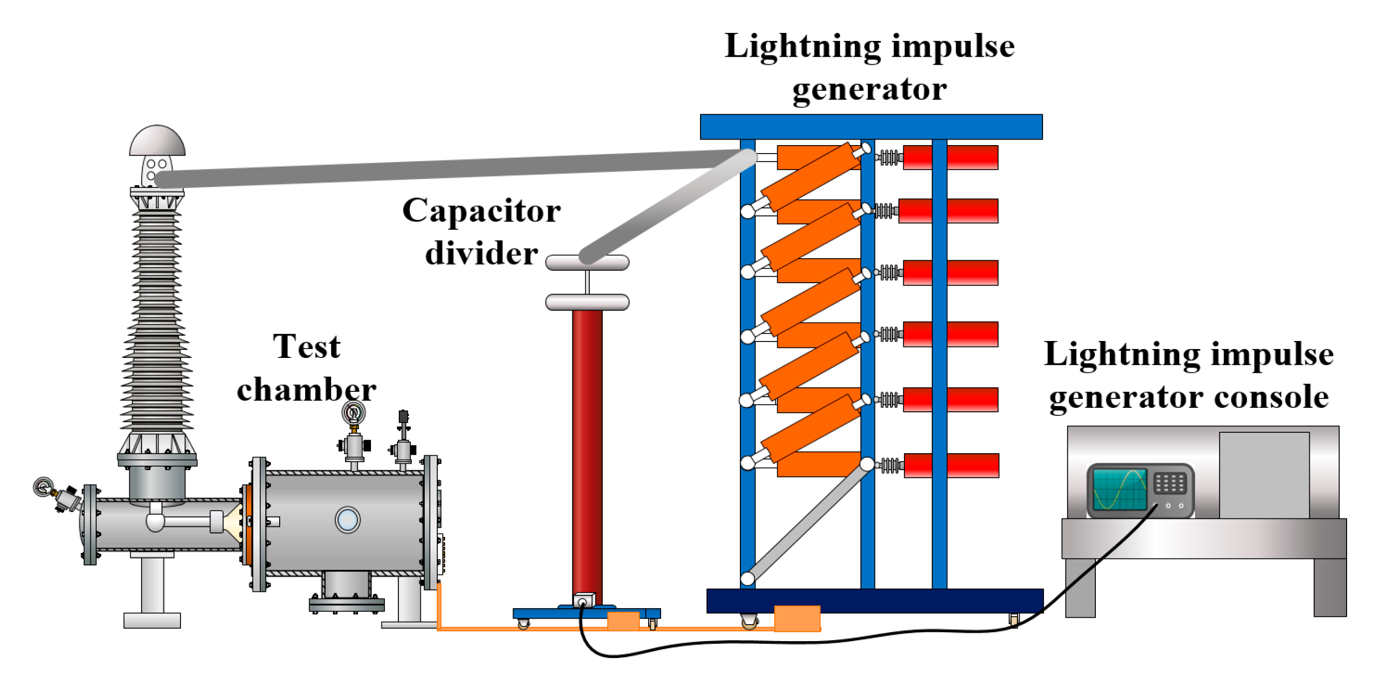
2.1. Experimental Setup

The impulse test platform (Figure 1) includes a 600 kV impulse voltage generator, a capacitive voltage divider (ratio 1870:1) and a Tektronix DPO2022B oscilloscope (1 GHz sampling rate, 200 MHz bandwidth).The manufacturer of the first two is China Leiyu Company (Yangzhou, China). The oscilloscope is from Tektronix in Beaverton, OR, USA. The test chamber (490 kV withstand voltage, 1 MPa pressure limit) features adjustable electrodes (spacing accuracy: 0.01 mm) and quartz observation windows.
The high melting point advantage of tungsten is as follows: The melting point of tungsten (3410 °C) is much higher than that of copper (1085 °C), and tungsten–copper alloys can maintain structural stability at high temperatures, avoiding electrode melting or deformation caused by local high temperatures. Anti-arc erosion: In electrical discharge machining or high-voltage discharge, the electrode surface is susceptible to instantaneous high-temperature arc impact. The high-temperature resistance of tungsten–copper alloys can significantly reduce electrode wear and extend service life [17]. Due to the above advantages, we chose tungsten–copper alloy electrodes under frequent arc impact conditions, as shown in Figure 2.
The nonuniformity factor f is defined as follows:
f = E max E ave
E ave = U d d
Electrode configurations (plate-plate, sphere-plate, and needle-plate) simulate uniform (f ≈ 1), slightly nonuniform (1 < f < 2), and highly nonuniform (f > 4) electric fields. The highly nonuniform (f > 4) electric field used to simulate faults in electrical equipment.
The calculation is shown in Formula (1), where Emax is the maximum electric field strength between electrodes, which is obtained by electrostatic-field simulation calculation.
The electrode material is set to copper. The relative dielectric constant of the SF6 or C4F7N/CO2 mixed gas is also set to 1.00 here. In Formula (1), Eave is the average electric field strength between electrodes, d is the electrode spacing, and Ud is the applied voltage. Use Formula (2) to calculate Eave. In this paper, different electrode forms are used, and the electrode gap distance is 2.5~10 mm, as shown in Table 1.

2.2. Methodology

In order to reduce the interference of moisture on the test results, when the C4F7N/CO2 mixed gas is configured, the purity of the C4F7N and CO2 pure gas used is 99.99%, and the steel cylinder configured with the mixed gas is vacuumized for at least 2 h.
n 1 n 2 = P 1 P 2
In this paper, the percentages of C4F7N in the C4F7N/CO2 mixture are all molar percentages. If the gas is regarded as an ideal gas, because the volume of the cavity is constant, according to Dalton’s partial pressure law, as shown in Formula (3), n1 and n2 are the moles of the two gases, and P1 and P2 are the gas pressures of the two gases. The molar ratio of C4F7N to C4F7N/CO2 gas mixture is the ratio of the pressure of the gas to that of C4F7N/CO2 gas mixture, which can be used for gas distribution according to the pressure ratio. After mixing C4F7N with CO2 and standing, the C4F7N component analyzer calibrated by the China Institute of Metrology is used for secondary analysis to ensure the mixing proportion accuracy.
Before the test, the interior of the chamber shall be wiped with dust-free paper dipped with anhydrous alcohol and then gas-dried. Fill the test chamber with test gas through the gas distribution pipeline on the gas distribution vehicle. Vacuumize the cavity and then charge the gas to be tested for gas washing. Before the discharge test, the gas shall be washed at least three times to avoid the interference of other gases in the chamber. First, fill the chamber with the test gas with the highest pressure in the form of this group of electrodes. After the gas pressure test, use the valve to discharge the gas and vacuum it. Take out the electrode for grinding and cleaning with alcohol. After reinstalling the electrode in the test chamber, fill in the mixed gas with another pressure value to test the pressure of the next group. Repeat the previous operation method, so as to avoid the error of electrode ablation and gas-discharge decomposition on the next group of tests. The impulse breakdown test shall be conducted by the voltage rise and fall method, and at least 20 effective breakdowns shall occur in each group.
According to references [8,9], the proportion of mixed gas is 9% C4F7N/91% CO2. The DC, power frequency, and lightning impulse insulation properties are close to SF6, and the liquefaction temperature can adapt to an environment as low as −15 °C. It has great potential to replace SF6 as the insulating gas in Gil.
Standard lightning impulse waveforms (1.2/50 µs) comply with IEC 60060 [12]. By up and down measuring method obtain the 50% impulse breakdown voltage in Figure 3. Then, 50% impulse breakdown voltage was found through the red line.
After statistical processing of each group of test data, calculate the standard deviation σ under each group of test conditions according to Formula (4), and then compare the standard deviation with the 50% impulse breakdown voltage U50% under this group of test conditions to obtain the size of dispersion, see Formula (5). For convenience, we use DISP to express it. The formulas are as follows:
σ = 1 N i = 1 N ( x i μ )
D I S P = σ U 50 % × 100  ( % )

3. Results and Analysis

3.1. Effect of Pressure on Dispersion

(1) Under the uniform-electric-field plate electrode, the electrode spacing is 2.5 mm and the electric field nonuniformity is f = 1.05. The gas pressure values described in this paper are absolute gas pressure values. And the variation trend of the impulse discharge voltage dispersion of C4F7N/CO2 mixed gas and SF6 gas with the change in gas pressure under positive lightning impulse voltage (+Li) and negative lightning impulse voltage (−Li) is shown in Figure 4a. The DISP of the C4F7N/CO2 mixture and SF6 gas decreased with the increase in pressure under positive and negative impulse voltage and showed a linear trend. If linear fitting was used, the linear goodness of fit R2 of each curve reached 0.97~0.99. It can also be seen from the figure that the DISP of 9%C4F7N/91%CO2 mixed gas is significantly less than that of SF6 gas under both positive and negative lightning impulse voltages. When SF6 gas is under atmospheric pressure, the positive DISP exceeds the general standard of 3%.
(2) Considering the electric field nonuniformity in actual electrical equipment, the electric field nonuniformity f is in the range of a slightly nonuniform electric field [3].
Under the condition of sphere-plate electrodes d = 5 mm, the trend of DISP change with the change in gas pressure is shown in Figure 4b.
Similarly to Figure 4a, the DISP of C4F7N/CO2 mixture and SF6 gas decreases with the increase in pressure under positive and negative impulse voltages, but the linearity is significantly different from that of uniform electric field. If linear fitting is considered, the linearity R2 of each curve is only 0.88~0.93. It can be seen from Figure 4a,b that the dispersion of positive polarity DISP is significantly higher than that of negative polarity DISP under a uniform electric field and a slightly uneven electric field for the same gas under an impulse voltage of different polarity. This is consistent with the polarity effect law of lightning impulse 50% breakdown voltage U50% under positive and negative impulse voltages.
When the electrode spacing in the sphere-plate electrode increases, the electric field changes from slightly uneven to extremely uneven to simulate faults in electrical equipment.
At this time, when the gas pressure is low, the dispersion of positive and negative polarity impulse voltage exceeds the general requirement of 3%. With the increase in gas pressure, the dispersed DISP of breakdown voltage at positive lightning impulse voltage decreases slightly at first, then decreases abruptly, and finally gradually tends to saturation. When the gas pressure is 0.2~0.3 MPa there is a sudden drop, while when the gas pressure is about 0.4 MPa the DISP tends to saturation. At negative lightning impulse voltage, DISP gradually decreased with the increase in gas pressure, and the goodness of linear fitting R2 was 0.96~0.98. The DISP of C4F7N/CO2 gas mixture under positive and negative polarity is crossed, and the DISP of the negative polarity exceeds that of the positive polarity with the increase in gas pressure.
(3) When the electrodes are needle-plate electrodes, as in Figure 4d–f, the DISP of 9% C4F7N/91% CO2 gas mixture is almost unchanged with the increase in gas pressure, while the dispersion of the positive polarity begins to drop sharply at 0.2 MPa.
For SF6 gas at a pressure of 0.1 MPa under uniform and slightly nonuniform electric fields, the DISP% range is 2.85–3.42%. Under extremely nonuniform electric fields, the DISP% range is 5.49–7.31%. When the pressure is 0.2 MPa, the DISP% ranges are 2.80–3.31% and 5.23–7.22%, respectively. When the pressure is 0.3 MPa, the DISP% ranges are 2.62–3.11% and 4.52–7.01%, respectively. For C4F7N/CO2 gas at a pressure of 0.1 MPa, under uniform and slightly nonuniform electric fields, the DISP% range is 2.71–3.11%. Under extremely nonuniform electric fields, the DISP% range is 4.47–6.01%. When the pressure is 0.2 MPa, the DISP% ranges are 2.41–2.96% and 4.36–5.94%, respectively. When the pressure is 0.3 MPa, the DISP% ranges are 2.34–2.61% and 3.12–5.82%, respectively. Please refer to Figure 4a–f for details.
With the increase in electrode spacing d, the electric field nonuniformity increases, and the change trend of each curve is almost unchanged. The DISP of negative polarity is higher than that of positive polarity. Under the same conditions, the dispersion of 9% C4F7N/91% CO2 gas mixture is lower than that of SF6 gas, and the dispersion decreases with the increase in pressure. The reason may be that the increase in the pressure of the insulating gas increases the number of moles of electronegative gas in the same volume cavity, and the length of the discharge random formation path can be considered to have little change when the electrode and spacing remain unchanged. However, with the increase in the gas density with strong adhesion ability, the ability of adsorbing electrons on each possible discharge path is enhanced, the probability of binding electrons that could have been randomly diffused increases, and the possibility of different paths is significantly reduced. According to the Townsend discharge mechanism, under low pressure, electrons continue to accelerate in a long mean free path, forming cascade ionization (electron avalanche), and the discharge area is relatively uniform. However, under high pressure, ionization is only concentrated in the strong-electric-field area (such as near the electrode), resulting in a narrow discharge channel and reduced dispersion. This mechanism has important guiding significance in high-voltage insulation designs, corona controls, and spark discharge applications.

3.2. Effect of Electric Field NonUniformity

Under the condition of 0.1~0.7 MPa absolute pressure, the variation trend of 9% C4F7N/91% CO2 mixed gas and SF6 gas impulse discharge voltage dispersion with the increase in electric field nonuniformity is shown in Figure 5.
No matter which type of electrode is used, the dispersion of breakdown voltage increases with the increase in electric field nonuniformity. For example, when the distance between the sphere-plate and the needle-plate is 20 mm, the dispersion of the needle-plate (f = 23.6) is significantly greater than that of the sphere-plate (f = 6.9).
According to the gas discharge theory, the reason may be that the maximum electric field intensity near the tip electrode increases with the increase in the electric field nonuniformity, which makes it easier to ionize a large number of free electrons. At the same time, with the increase in the distance between the tip and plate electrodes, the number of molecules in the electrode gap increases. That is, more free electrons and ions can be produced, but the path is mainly determined by the free electrons moving faster, and the diffusion and drift of free electrons are more intense, which affects the discharge path and makes the randomness of the discharge path increase. That is, the more dispersed DISP results are obtained statistically.
At 0.1~0.7 MPa absolute pressure and under different pressure conditions, the DISP of 9% C4F7N/91% CO2 mixture and SF6 gas showed different degrees of saturation trends with the increase in electric field heterogeneity. When the pressure is low and the absolute pressure p = 0.1 and 0.2 MPa, the dispersion of SF6 gas and 9% C4F7N/91% CO2 mixture changes from increasing to saturation when the electric field nonuniformity reaches around 6.9. When the pressure is high, that is, when the pressure reaches 0.3 MPa, the DISP of SF6 gas will still show a saturation trend; however, the 9% C4F7N/91% CO2 gas mixture is not saturated, showing a trend of increasing with the increase in electric field nonuniformity. Therefore, when the pressure is high, the sensitivity of the DISP of 9%C4F7N/91% CO2 mixture to electric field nonuniformity is greater than that of SF6.

4. Discussion

(1) The nonuniformity of internal electric field of gas-insulated equipment without defects and flaws generally ranges from 1.6 to 2.5 [13]. Figure 4b test results are in this range. In order to prevent the dispersion of impulse discharge in gas-insulated equipment from exceeding the standard requirements, it is necessary to monitor the gas pressure in the equipment. For example, once the pressure of SF6 gas is lower than 0.3 MPa absolute pressure, the stability of impact insulation performance of the gas gap will decline, which may lead to a decline in the insulation margin and cause accidents.
(2) According to Figure 5, it can be concluded that if the gas pressure meets the conditions (higher than 0.3 MPa), it also needs to meet certain conditions for the electric field nonuniformity to make the DISP meet the requirements of less than 3%. That is, the electric field nonuniformity should be less than or equal to 2.4, which is a slightly uneven electric field. It is necessary to keep the inside of the closed cavity free of defects and flaws. According to the classical theory of gas discharge, when the nonuniformity of the electric field increases to a certain extent, it may cause the development of electron avalanche to be almost completely concentrated in the high-field-strength region, and unable to expand to the low-field-strength region. At this point, even if the unevenness of the electric field is further increased (such as making the needle sharper or the pole spacing smaller), the discharge can still only develop in the high-field-strength region, resulting in no significant change in dispersion, that is, approaching saturation. This may be related to the accumulation of space charges, as a large number of charges are concentrated in high-field-strength regions, and the generated space-charge field partially offsets the external electric field, limiting the further expansion of discharge.

5. Conclusions

(1) By comparing the DISP of SF6 and C4F7N/CO2 under the same conditions, the feasibility of replacing SF6 gas is considered from the perspective of insulation stability. Under the same pressure of 0.1~0.7 MPa, the dispersion DISP of discharge voltage of 9%C4F7N/91%CO2 is less than SF6 in uniform electric field, slightly uneven electric field and extremely uneven electric field. That is, the stability of lightning impulse insulation performance of 9% C4F7N/91% CO2 is better than SF6.
(2) With an increase in pressure, 9%C4F7N/91%CO2 and SF6 lightning impulse discharge voltage DISP gradually decreased. At the same time, the DISP of both increased with an increase in the electric field nonuniformity. In engineering, the interior of the closed cavity is usually in a slightly uneven electric field. When the pressure is lower than 0.3 MPa, 9%C4F7N/91%CO2 and SF6 gas cannot meet the requirements. Therefore, it is necessary to monitor the pressure in the cavity and adjust the pressure range reasonably. The inflation range of high-voltage equipment in the project is high pressure, and the internal electric field distribution of the cavity is slightly uneven when there is no defect, so 9%C4F7N/91%CO2 and SF6 can meet the dispersion requirements.
(3) Before operation or during operation, if there are defects or flaws inside the cavity, making the electric field nonuniformity greater than 2.4, although the internal pressure of the cavity has met the conditions the discharge dispersion of 9%C4F7N/91%CO2 and SF6 cannot meet the requirements. Therefore, the defects and flaws inside the cavity should be avoided as strictly as possible. The variation in pressure and electric field nonuniformity in equipment can affect dispersion, thereby affecting the stable operation of the equipment. Through the research in this article, the appropriate range of air pressure and electric field nonuniformity has been obtained, which is of great significance for the safe operation of electrical equipment using SF6 gas and C4F7N/CO2 gas. The contribution of new gases to environmental protection will be significant.

Author Contributions

Conceptualization and methodology, T.Z.; formal analysis, F.H.; data curation, T.Z. and L.C.; writing—original draft preparation, T.Z.; project administration and funding acquisition, L.C. and W.Z. All authors have read and agreed to the published version of the manuscript.

Funding

This research was funded by Research on the Theory and Method of Inertial Navigation Information Fusion Based on Li Qun State Representation, Project No. 62373367, Naval Engineering University, General Project of China Natural Science Foundation. Research on Underwater Target Characteristic Modeling and Weak Signal Detection Technology Based on Corrosion Related Electric Fields, General Project of Hubei Provincial Natural Science Foundation of China, No. 2025AFB921. The National Key R&D Program of China (No. 2017YFB0902500), Science and Technology Project of SGCC (The Key Technology of Environment-friendly Gas-insulated Transmission Line).

Data Availability Statement

Do not share data.

Conflicts of Interest

The authors declare no conflict of interest.

Abbreviations

The following abbreviations are used in this manuscript:
GILGas-insulated line
DISPDispersion

References

  1. Cressault, Y.; Connord, V.; Hingana, H.; Teulet, P.; Gleizes, A. Transport properties of CF3I thermal plasmas mixed with CO2 gas or N2 as an alternative to SF6 plasmas in high-voltage circuit breakers. J. Phys. D-Appl. Phys. 2011, 44, 495202. [Google Scholar] [CrossRef]
  2. Zhao, H.; Li, X.; Zhu, K.; Wang, Q. Study of the arc interruption performance of SF6/CO2 mixtures as a substitute for SF6. IEEE Trans. Dielectr. Electr. Insul. 2016, 23, 2657–2667. [Google Scholar] [CrossRef]
  3. Li, P.; Yan, X.; Wang, H.; Zhang, Q.; Jin, G.; Gao, Y.; Mu, S. Research and application of UHVAC gas-insulated transmission line. Power Syst. Technol. 2017, 41, 3161–3167. [Google Scholar]
  4. Kieffel, Y.; Irwin, T.; Ponchon, P.; Owens, J. Green Gas to Replace SF6 in Electrical Grids. IEEE Power Energy Mag. 2016, 14, 32–39. [Google Scholar] [CrossRef]
  5. Liu, T.; Sun, H.; Li, G.; Zhang, Y.; Wang, J.; Xiao, J. Decay characteristic of gas arc in C4F7N/N2 and C₄F₇N/CO₂ gas mixture by thomson scattering. J. Phys. D Appl. Phys. 2025, 58, 045203. [Google Scholar] [CrossRef]
  6. Zhao, H.; Li, X.; Tang, N.; Jiang, X.; Lin, H. Dielectric Properties of fluoronitriles/ CO2 and SF6/N2 mixtures as a possible SF6-substitute gas. IEEE Trans. Dielectr. Electr. Insul. 2018, 25, 1332–1339. [Google Scholar] [CrossRef]
  7. Tu, Y.; Cheng, Y.; Wang, C.; Ai, X.; Zhou, F.; Chen, G. Insulation Characteristics of fluoronitriles/CO2 gas mixture under DC electric field. IEEE Trans. Dielectr. Electr. Insul. 2018, 25, 1324–1331. [Google Scholar] [CrossRef]
  8. Zhang, T.; Zhou, W.; Yu, J.; Yu, Z. Insulation properties of C4F7N/CO2 mixtures under lightning impulse. IEEE Trans. Dielectr. Electr. Insul. 2020, 27, 159–166. [Google Scholar] [CrossRef]
  9. Zhang, T.; Chang, L.; Zhou, W. Study on Impulse Discharge Voltage Calculation of Environmentally Friendly Insulation Gas in Slightly Non-Uniform Electric Field. Electronics 2025, 14, 2116. [Google Scholar] [CrossRef]
  10. Hu, S.; Qiu, R.; Zhou, W. Dielectric properties and synergistic effect evaluation method of C4F7N mixtures. IEEE Trans. Dielectr. Electr. Insul. 2024, 31, 793–800. [Google Scholar] [CrossRef]
  11. Li, X.L.; Liu, L.; Wang, W.; Geng, Z.X. Analysis of breaking characteristics of C4F7N/CO2 mixture gas in circuit breaker. Energies 2024, 17, 2638. [Google Scholar] [CrossRef]
  12. Nechmi, H.E.; Beroual, A.; Girodet, A.; Vinson, P. Fluoronitriles/CO2 gas mixture as promising substitute to SF6 for insulation in high voltage applications. IEEE Trans. Dielectr. Electr. Insul. 2016, 23, 2587–2593. [Google Scholar] [CrossRef]
  13. Zhao, S.; Xiao, D.; Zhang, H.; Deng, Y. Investigation on discharge polarity effect of CF3I/N2 Gas mixtures under lightning impulse. Proc. CSEE 2017, 37, 3636–3642. [Google Scholar]
  14. Wen, T.; Zhang, Q.; Guo, C.; Zhang, L.; Ma, Y.; Tan, X. Reversal phenomenon of discharge polarity effect in SF6 needle-plate gap under impulse voltage. High Volt. Eng. 2015, 41, 275–281. [Google Scholar]
  15. IEC 60060; High-Voltage Test Techniques-Part 1: General Definitions and Test Requirements. IEC: Geneva, Switzerland, 2010.
  16. Zhang, X.; Xiao, S.; Han, Y.; Cressault, Y. Experimental studies on power frequency breakdown voltage of CF3I/N2 mixed gas under different electric fields. Appl. Phys. Lett. 2016, 108, 092901. [Google Scholar] [CrossRef]
  17. Wei, H.; Sun, F.; Liu, P.; Jiang, X.; Wang, Z. ±100 kV three-electrode field-distortion gas spark switch. High Power Laser Part. Beams 2012, 24, 881–884. [Google Scholar] [CrossRef]
Figure 1. Experimental platform.
Energies 18 03228 g001
Figure 2. Experimental electrodes.(a) Needle electrode. (b) Sphere electrode. (c) Plate electrode.
Energies 18 03228 g002
Figure 3. An experimental example of up and down measuring method.
Energies 18 03228 g003
Figure 4. The influence of pressure on C4F7N/CO2 and SF6 breakdown voltage DISP with different electrodes. (a) Plate-plate electrodes, electric field nonuniformity = 1.05. (b) Sphere-plate electrodes, electric field nonuniformity = 2.4. (c) Sphere-plate electrodes, electric field nonuniformity = 6.9. (d) Needle-plate electrodes, electric field nonuniformity = 13.8. (e) Needle-plate electrodes, electric field nonuniformity = 18.9. (f) Needle-plate electrodes, electric field nonuniformity = 23.6.
Energies 18 03228 g004
Figure 5. The influence of f on C4F7N/CO2 and SF6 breakdown voltage DISP on different pressures. (a) p = 0.1 MPa. (b) p = 0.2 MPa. (c) p = 0.3 MPa. (d) p = 0.4 MPa. (e) p = 0.5 MPa. (f) p = 0.6 MPa, (g) p = 0.7 Mpa.
Energies 18 03228 g005aEnergies 18 03228 g005b
Table 1. The electric field nonuniformity of different electrode types.
Electrode TypesRadius/mmd/mmElectric Field Nonuniformity
f
Plate-plate electrodes/2.51.01
Sphere-plate electrodes352.4
3206.9
Needle-plate electrodes0.51013.8
0.51518.9
0.52023.6
Disclaimer/Publisher’s Note: The statements, opinions and data contained in all publications are solely those of the individual author(s) and contributor(s) and not of MDPI and/or the editor(s). MDPI and/or the editor(s) disclaim responsibility for any injury to people or property resulting from any ideas, methods, instructions or products referred to in the content.

