

Review on Research and Development of Magnetic Bearings


Abstract
1. Introduction
- 1.
- Concept Exploration Period (1842–1960):In 1842, Earnshaw introduced the concept of magnetic levitation and demonstrated that stable levitation of ferromagnetic materials in all degrees of freedom cannot be achieved using only permanent magnets, thereby establishing the mathematical foundation of magnetic levitation theory [12]. In 1937, Kemper filed the first patent related to magnetic levitation technology and proposed the use of actively controlled electromagnets for achieving stable levitation—a milestone in the development of magnetic bearings and maglev transportation systems [13,14].
- 2.
- Technology Development Period (1960–1990):Between the 1950s and 1960s, Beams successfully applied magnetic levitation to ultra-high-speed centrifuges, marking the first implementation of magnetic support for rotating bodies [15]. In 1972, the LRBA Laboratory pioneered the application of magnetic bearings in satellite reaction wheels, setting a precedent for engineering applications of the technology [16].
- 3.
- Engineering Application Period (1990–Present):In 1983, the United States employed a magnetic bearing vacuum pump aboard the Space Shuttle, demonstrating its reliability under extreme conditions [17]. By 1997, Draper Laboratory reported a series of advancements in high-temperature magnetic bearings capable of operating at 510 °C for aerospace engine applications [18]. As of 2021, magnetic levitation technology has been widely adopted in molecular pumps, blowers, compressors, and other industrial systems [19,20,21]. According to industry reports [22,23,24,25], the global magnetic bearing market size was about $2 billion in 2023 and is expected to grow to about $3.34 billion by 2032, with a compound annual growth rate (CAGR) of about 5.96% from 2024 to 2032. The top five manufacturers include SKF, Schaeffler, Siemens, GE and NSK, which together occupy more than 60% of the market share.
- Section 2 discusses the classification and operating principles of magnetic bearings, including the technical characteristics and comparisons of active, passive, and hybrid types.
- Section 3 focuses on core technologies, including structural design, control algorithms, and drive systems.
- Section 4 presents typical application scenarios in energy, transportation, industrial systems, and other domains.
- Section 5 addresses current technical challenges and explores future development trends.
- Section 6 concludes the review with final remarks.
2. Classification and Comparison of Magnetic Bearing
- Type of Magnetic Force: Attractive or repulsive forces.
- Suspension Mode: Active, passive, or hybrid systems.
- Magnet Type: Superconducting, permanent magnet, or electromagnetic.
- Structural Configuration: Horizontal or vertical orientation; internal or external rotor.
- Degree of Contact: Fully non-contact or partially contact-based systems.
- Control Current Type: Alternating current (AC) or direct current (DC).
- Magnetic Pole Arrangement: Heteropolar or homopolar configurations.
- Degrees of Freedom (DOF): Axial (1 DOF), radial (2 DOF), combined radial-axial (3 DOF), or extended to 4 and 5 DOF systems.
2.1. Classification of Magnetic Bearing
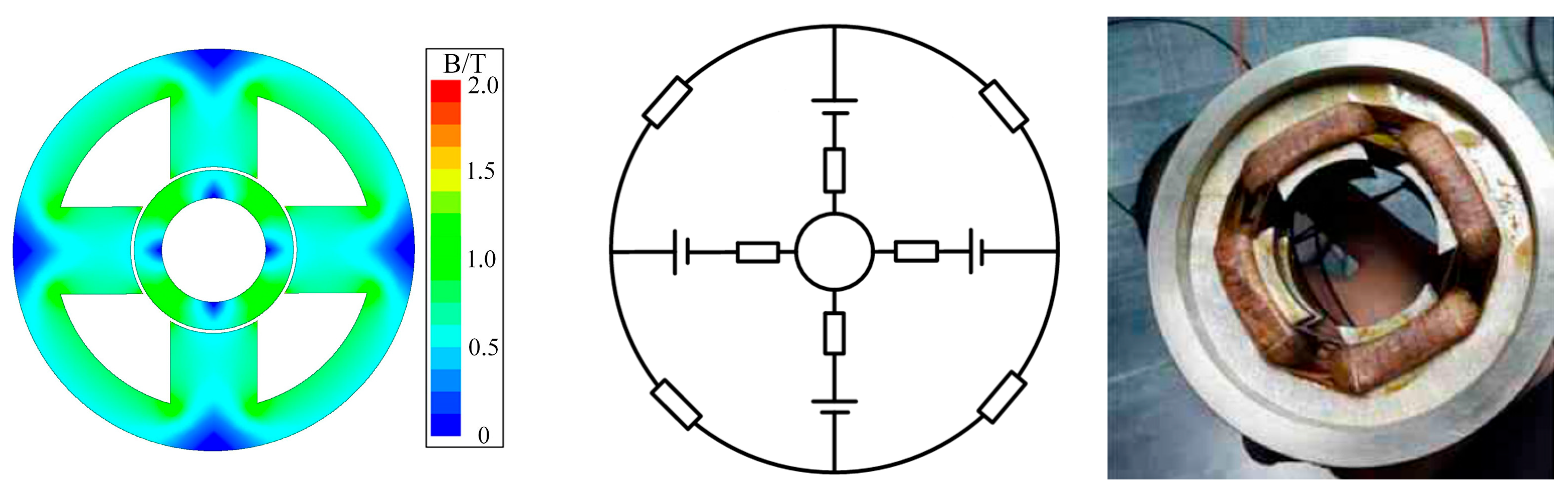
2.1.1. Active Magnetic Bearings
2.1.2. Passive Magnetic Bearings
- Superconducting Magnetic Bearings,
- Diamagnetic Magnetic Bearings and
- Permanent Magnetic Bearings.
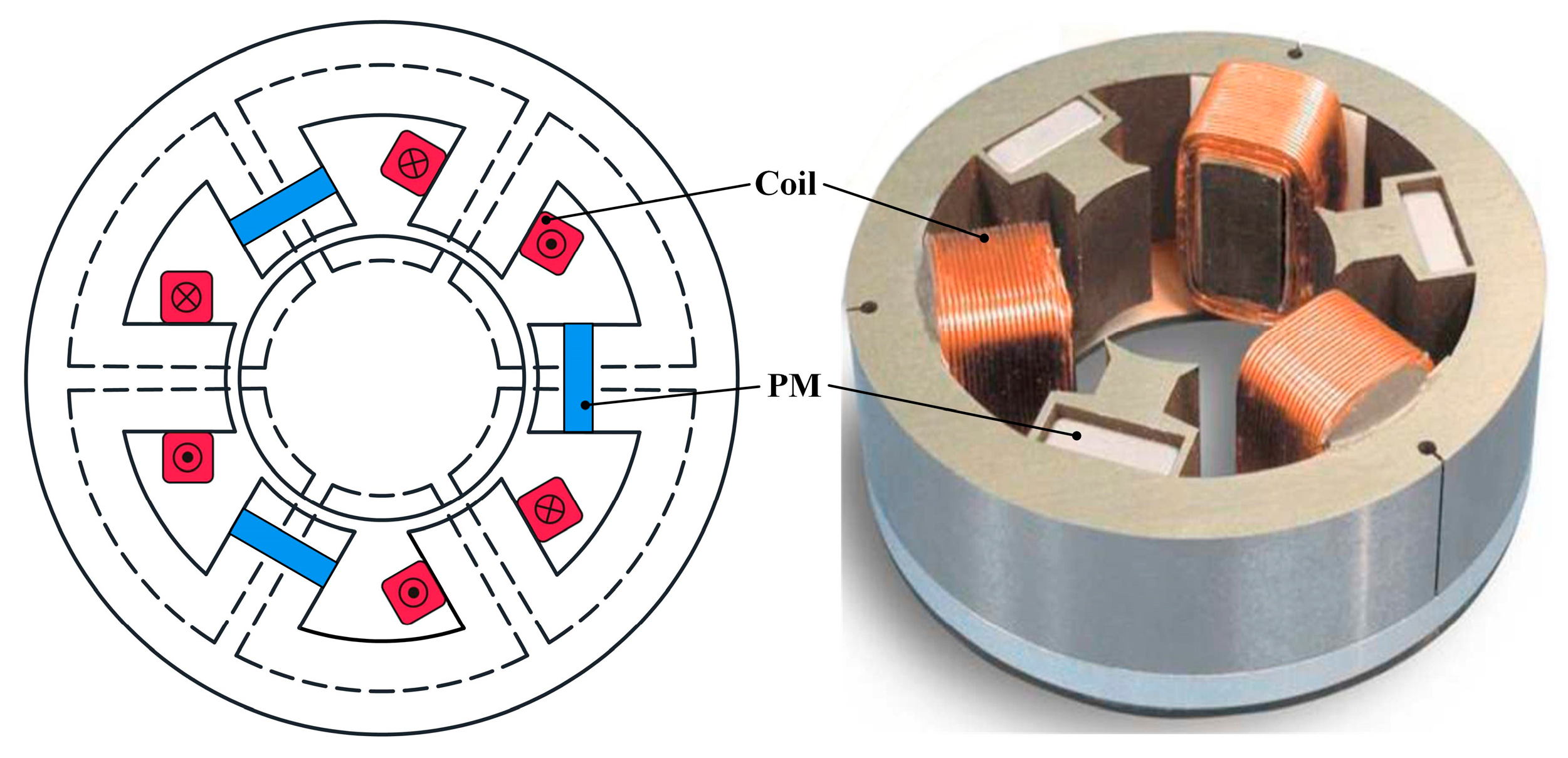
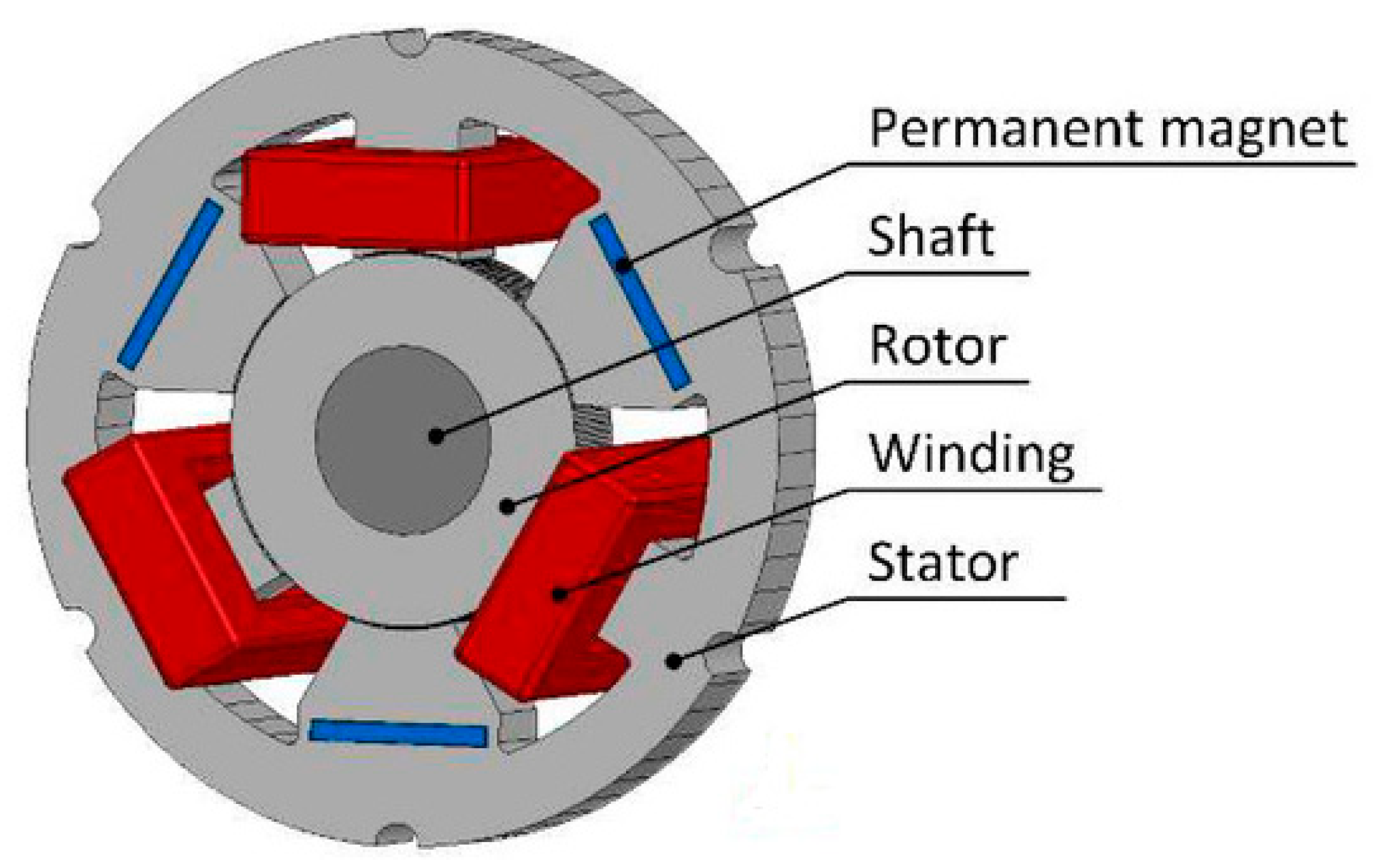
2.1.3. Hybrid Magnetic Bearings
2.2. Comparison of Magnetic Bearing
3. Research Progress on Key Technologies of Magnetic Bearing
3.1. Topology and Modeling
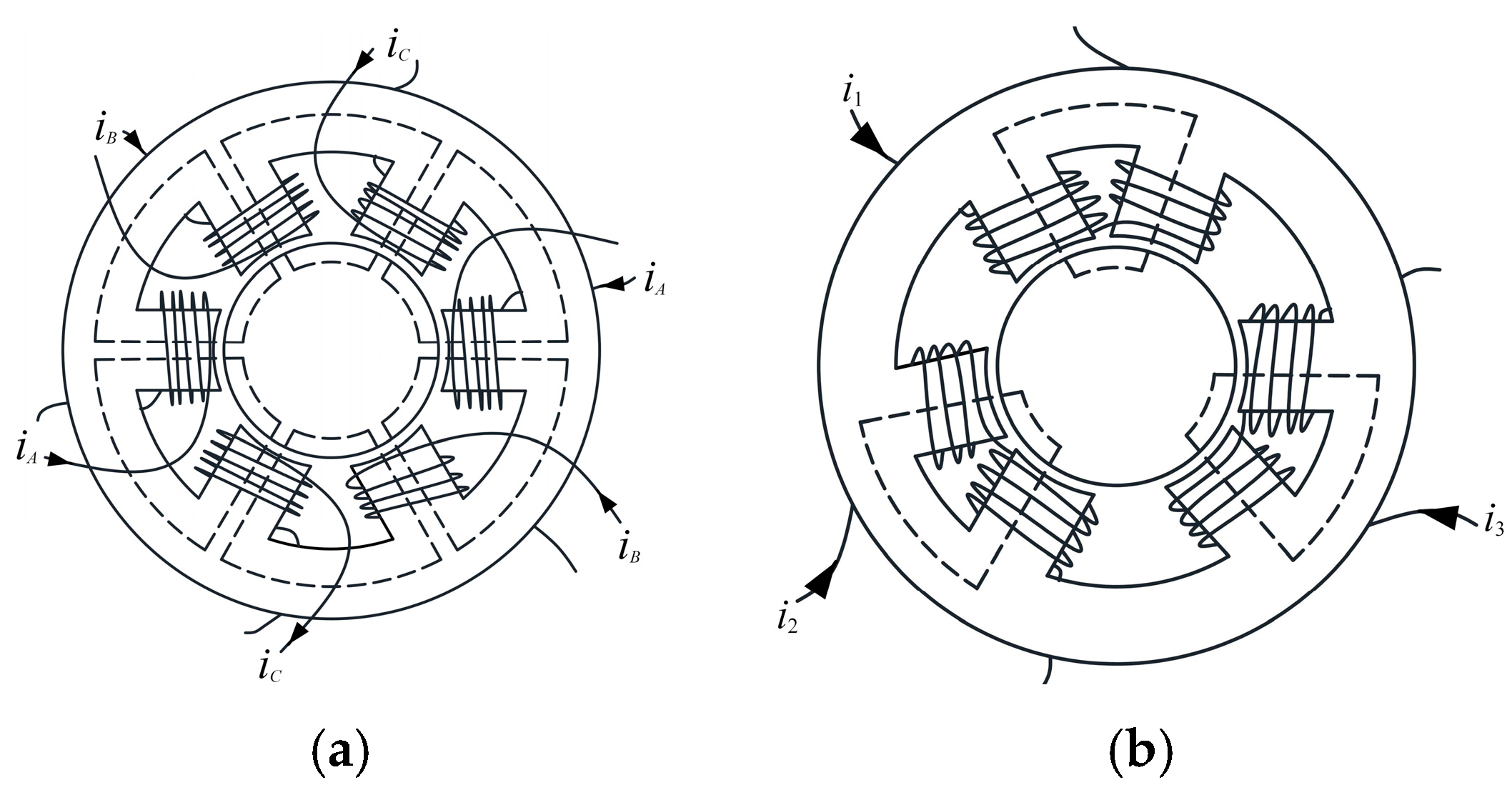
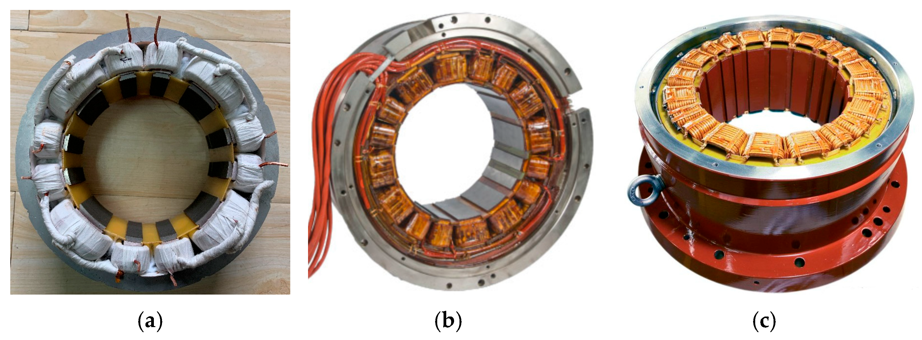
3.1.1. Bearing Topologies
3.1.2. Modeling of Electromagnetic Force
- 1.
- Equivalent Magnetic Circuit MethodThe equivalent magnetic circuit method (EMC) is the most classical modeling method for the electromagnetic force of magnetic bearings, which is widely used in AMB and HMB [44,77,81,82,83,84,85,86,87,88]. EMC simplifies the topological relationship of the magnetic circuit and decomposes the magnetic circuit into series or parallel reluctances for calculation. It is suitable for magnetic bearing structures with relatively regular magnetic field distribution. For ease of calculation, only the working air-gap reluctance is generally considered, while the leakage reluctance and the core reluctance are ignored. The advantage of this method is its high calculation efficiency (more than 10 times faster than FEM), but the leakage effect needs to be corrected through the leakage coefficient compensation, with an error of approximately 5% to 10%.
- 2.
- Maxwell Tensor MethodBased on Maxwell’s equations, the electromagnetic force is calculated by integrating the air-gap magnetic field tensor, which is especially suitable for modeling the radial force of AC magnetic bearing [49,89,90,91,92,93,94,95,96]. In [91], an accurate radial force model is established for bearingless motors and quantifies the suspension force through the air-gap flux density component. The stiffness of the magnetic bearing is analyzed and quantified by the Maxwell tensor method in [49], and the error can be within 3%.
- 3.
- Equivalent Magnetic Charge MethodThe general magnetic circuit model proposed by Yonnet assumes that the PM is infinite in length, and the magnetic force analytical formula of PMB is derived by combining the equivalent magnetic charge method [97]. This method equivalents the permanent magnet as a virtual magnetic charge distribution and calculates the magnetic force in combination with Coulomb’s law. According to the force relationship between the magnetic charges at two points, the numerical integration model of axial, radial, and Halback magnetized PMB can be established [98,99,100,101]. However, the numerical calculation methods of the model are generally complicated.
- 4.
- Magnetic Network MethodBased on EMC, the magnetic network (MN) method constructs nonlinear equations by further discretizing the magnetic circuit nodes, which takes into account both computational efficiency and accuracy. For spherical magnetic bearings, the magnetic field is segmented accurately based on the flux-tube principle, and the edge flux and flux leakage are calculated accurately [11]. A network model in a spherical coordinate system is established to quantify the multi-degree freedom coupling effect, and more accurate calculation results are obtained.
- 5.
- Subdomain MethodThe subdomain method divides the magnetic field region into linear subdomains (such as air gaps, cores, and PMs) and solves them by the magnetic field boundary conditions. The magnetic field problem in sub-regions can be solved by using the vector magnetic potential within each sub-region. In [102,103,104], the radial AMB is divided into air-gap domain and slot domain. The zero-order equation and first-order equation of the magnetic field are calculated in polar coordinates, and the distribution of the magnetic field is obtained by using the method of variable separation.
- 6.
- Finite element methodThe finite element method (FEM) is the preferred tool for complex geometry and nonlinear material modeling, which has the highest accuracy and can construct multi-physics coupled models. However, the preprocessing and calculation time of the model are long, which limits the efficiency of design optimization and the speed of system-level simulation.
3.2. Control Strategy
3.2.1. Classical PID Control
3.2.2. Advanced Control Algorithm
- 1.
- Robust controlRobust control ensures the system stability under parameter variations or external disturbances by designing controllers that are insensitive to uncertainties, parameters in the model and disturbances. In the magnetic bearings, the robust controller based on μ analysis effectively deals with the high-frequency vibration and modal coupling problems in the rotor dynamics through frequency domain analysis and pole configuration and improves the stability margin of the system. Plus, H∞ control is applied to solve the mode control problem of the magnetic bearing rotor system. The system identification model is established by the orthogonal polynomial fitting method, and the stable suspension and mode suppression of the rotor are realized.
- 2.
- Model Predictive Control (MPC)MPC predicts future system states and optimizes control inputs based on a system model, making it well-suited for multivariable coupled control in magnetic bearing systems. MPC based on the radial 4-DOF global control model can achieve high-precision tracking of the rotor position and transient response optimization using the state-space model and optimal controller design. This approach demonstrates excellent performance in high-speed rotating machinery. However, it also entails high computational complexity and depends heavily on high-performance processors for real-time implementation.
- 3.
- Sliding-mode control (SMC)SMC is extensively applied in the nonlinear control of magnetic bearings due to its strong robustness against parameter variations and external disturbances. By appropriately designing the sliding surface and control law, SMC ensures fast convergence and effectively suppresses rotor displacement fluctuations. In applications such as magnetic bearings for wind turbines, the integration of SMC with PID control has been shown to reduce overshoot and enhance response speed. However, the well-known chattering phenomenon associated with SMC remains a challenge and necessitates further improvement through techniques such as adaptive boundary layer design and higher-order sliding mode methods.
- 4.
- Neural network controlNeural networks can effectively model the complex behaviors of magnetic bearings by learning and approximating their nonlinear dynamics. A hybrid control architecture, integrating deep learning with PID feedback, is employed to design a compensation controller, significantly enhancing the suppression of unbalanced vibrations. Additionally, convolutional neural networks (CNN) and gated recurrent units (GRU) are utilized for fault prediction through the analysis of current waveforms and vibration spectra. However, neural networks face challenges, including a reliance on large volumes of training data and the need for optimization to meet real-time performance requirements.
- 5.
- Adaptive controlAdaptive control adjusts system parameters online to accommodate changes, with methods like Model Reference Adaptive Control (MRAC) and Active Disturbance Rejection Control (ADRC). In magnetic bearing control systems, the ADRC algorithm, utilizing an extended state observer, estimates and compensates in real time, thereby minimizing manual parameter adjustments. Intelligent optimization techniques, such as Beetle Antennae Search (BAS), are employed to fine-tune PID parameters, achieving rapid convergence and low energy consumption in multi-DOF magnetic bearings.
- 6.
- Fuzzy controlFuzzy control does not require the precise mathematical model of the plant or the detailed system dynamics. It is particularly suitable for dealing with the nonlinearity and uncertainty of the magnetic bearing system. It relies on the relationship between error, error rate and output and uses fuzzy reasoning based on control rules to adjust control decisions according to specific system conditions to meet requirements. It overcomes the limitation of traditional PID control that cannot be adjusted in real-time. It also saves the time required for manual control parameter debugging.
- 7.
- Active disturbance rejection controlAs an advanced Control method that does not rely on accurate models, Active Disturbance rejection control (ADRC) has been widely used in magnetic bearings in recent years. The core idea is based on real-time estimation and compensation of disturbance. The multi-DOF coupling effect of the magnetic bearing is estimated in real-time through the Extended State Observer (ESO), and the nonlinear feedback control law is combined to realize decoupling and disturbance rejection. ADRC only needs to design the controller based on the input and output data. This property is especially suitable for scenarios where the nonlinear dynamics of magnetic bearings are difficult to model accurately.
3.3. Power Drive System and Controller of Bearings
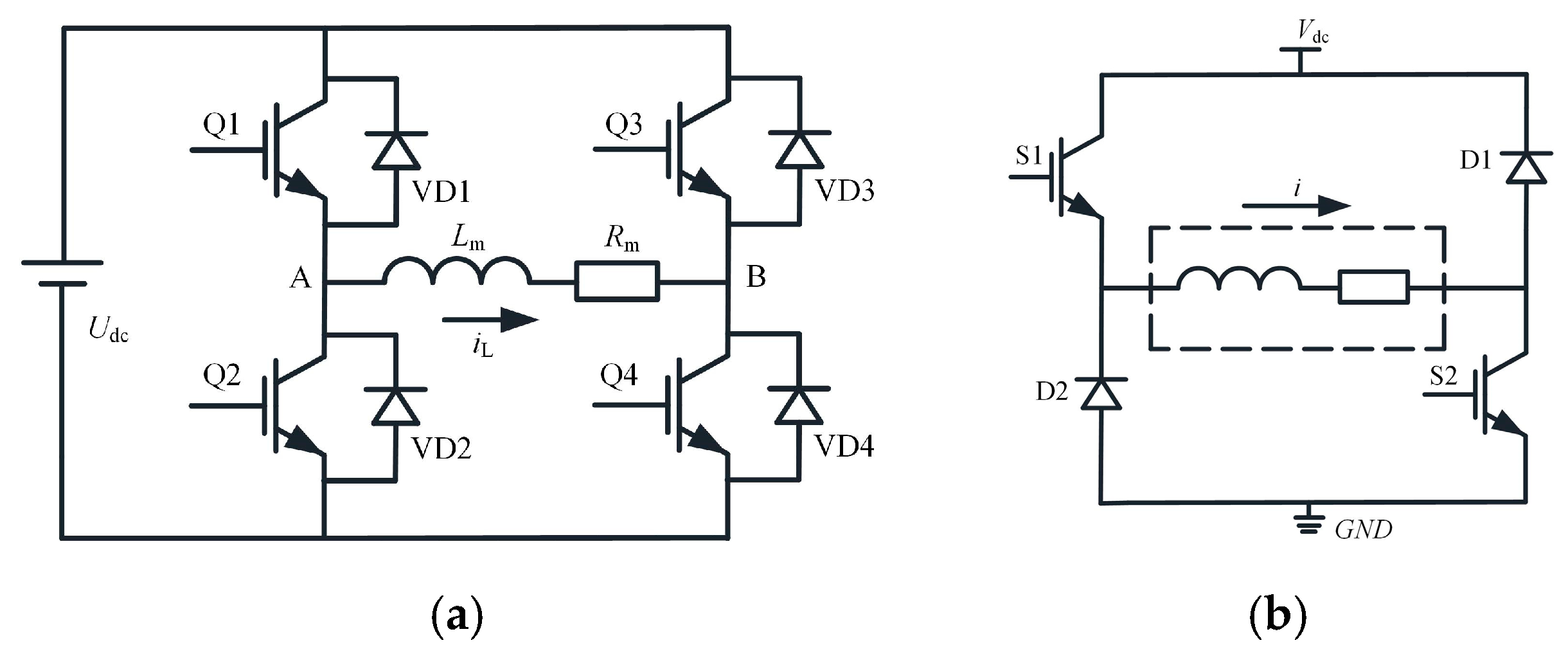
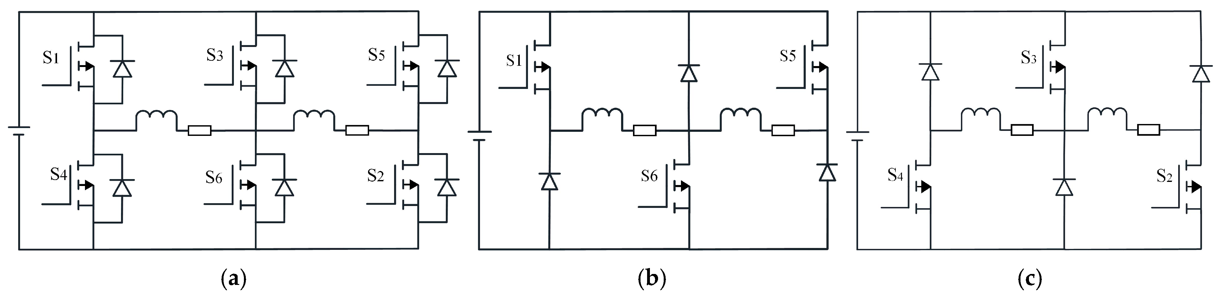
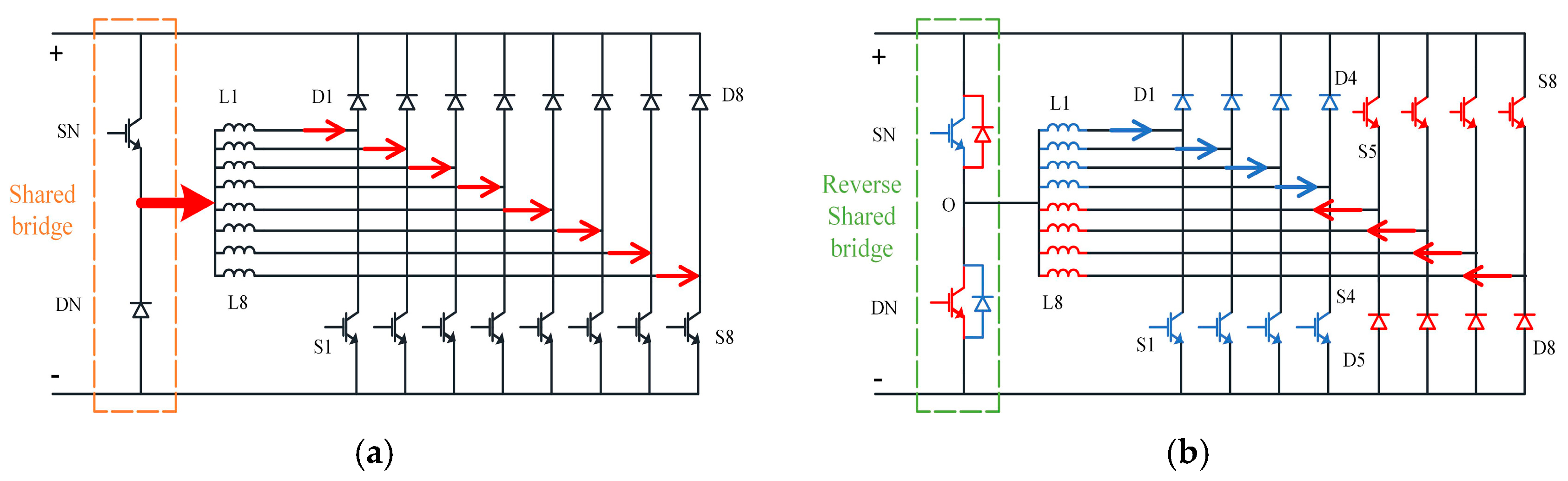
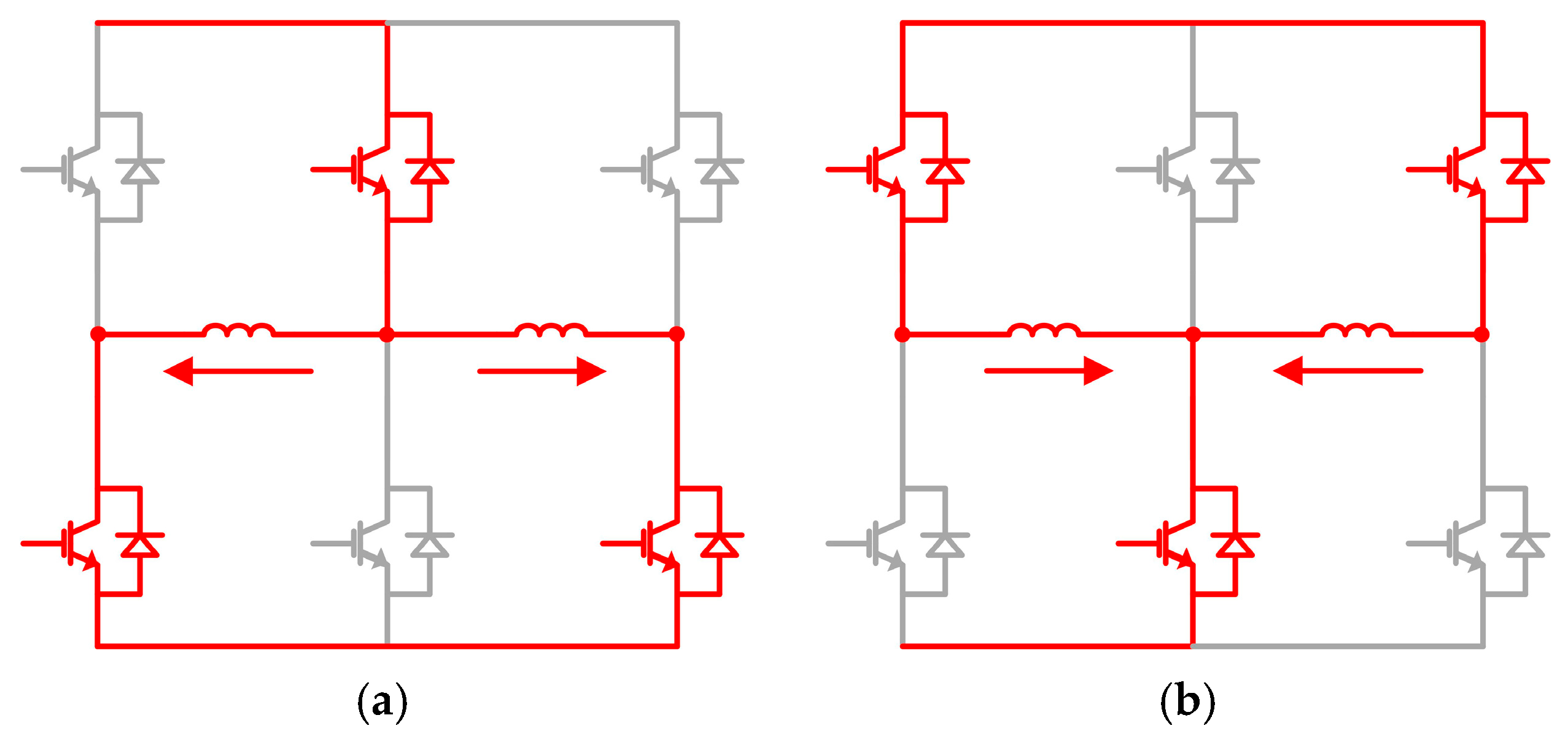
3.3.1. Driver Topology Design
3.3.2. Fault-Tolerant Control and Fault Detection
3.3.3. Controller Hardware Platform
- 1.
- Embedded MicrocontrollerThe STM32 series core microcontrollers are widely used in medium and low-complexity maglev systems due to their advantages of low power consumption, high integration and cost. For example, the STM32F4 series (main frequency of 180 MHz) captures the Hall sensor signal through a timer and combines the PID algorithm to achieve single-DOF suspension control with a displacement resolution of ±10 μm [157]. The CAN and Ethernet interfaces of STM32 can realize multi-axis cooperative control, but limited by the computing power, STM32 makes it difficult to meet the real-time requirements of high-speed multi-DOF systems.
- 2.
- Digital Signal ProcessorDigital Signal Processor (DSP) has become the mainstream scheme of dynamic control of magnetic bearing because of its high-performance floating-point operation ability and special peripheral equipment. The built-in redundant ADC module supports sensor fault detection and switching, which improves the fault tolerance of the magnetic bearing system. TMS320F28335 (main frequency 150 MHz) is adopted in [158,159] combined with a fault diagnosis algorithm, which can control the fault switching time of magnetic bearing in 5 ms and significantly improve the stability of the system.
- 3.
- Field Programmable Gate ArrayWith the characteristics of parallel processing and nanosecond delay, a Field Programmable Gate Array (FPGA) plays a key role in high-speed and multi-variable maglev systems. In the speed-holding mode of a high-speed maglev motor, the observation accuracy of steady-speed frequency is better than 5 Hz, and the response time is less than 50 μs [160,161].
4. Application Fields and Typical Cases
4.1. Industrial Field
4.1.1. High-Speed Motor and Compressor
4.1.2. Precision Machine Tool Spindle
4.2. Energy and Transportation Field
4.2.1. Flywheel Energy Storage System
4.2.2. Wind Turbine Spindle
4.3. Extreme Environments
4.3.1. Satellite Momentum Wheel
4.3.2. Nuclear Reactor Cooling
5. Technical Challenges and Future Trends
5.1. Technical Challenges
5.1.1. Multi-Field Coupled Modeling and Calculation
5.1.2. Balance Between System Cost and Reliability
5.2. Frontier Development Direction
5.2.1. Intelligent Control System
5.2.2. Miniaturized and Integrated Solutions
6. Conclusions and Perspectives
6.1. Technical Summary
6.2. Outlook
- Multi-Field Coupled modeling and Accurate Analysis: Magnetic bearings inherently involve the coupling of multiple fields, including electromagnetic, thermodynamic, and mechanical vibration. Future advancements will require the development of more precise multi-field coupling mathematical models to address complex challenges, such as nonlinear vibration and thermal deformation under high-speed and high-load conditions. For example, research could focus on the interaction between magnetic field distribution, thermal effects, and mechanical stress. Additionally, integrating these models with the flexural vibration characteristics of high-speed, flexible rotors will enable the development of response models capable of predicting instability thresholds at critical speeds.
- Innovation of Intelligent Control Algorithm and Strategy: To overcome the limitations of traditional PID control, such as insufficient disturbance rejection, it is essential to integrate modern control theory with artificial intelligence technologies to enhance the system’s robustness against sudden load changes and parameter variations. Employing deep reinforcement learning for control parameter optimization, along with multi-sensor data fusion (including displacement, current, and temperature data), will enable more precise suspension control and improve overall system stability. This approach promises to significantly enhance the adaptability and performance of magnetic bearing systems in dynamic environments.
- Efficient Optimization of Power Drive System: As the core execution unit of magnetic bearings, the power electronic converter must achieve breakthroughs in both topology structure and control efficiency. Advancing shared bridge topologies will reduce the number of power devices, thereby minimizing both the volume and cost of the system. The integration of wide-bandgap SiC/GaN devices will enable higher switching frequencies, while advanced PWM modulation strategies will further reduce losses and optimize operational efficiency. These innovations will significantly enhance the performance and cost-effectiveness of magnetic bearing systems.
- Miniaturization and Integration Design Trend: To meet the demands of medical, aerospace, and precision instrumentation applications, magnetic bearings must be miniaturized and modularized. Integrating the sensor, controller, and power amplifier into a single chip will streamline the system architecture, reduce power consumption, and enhance efficiency. Additionally, optimizing the topology structure is crucial to minimizing weight, which will further support the deployment of magnetic bearings in compact, high-performance systems. These advancements will enable magnetic bearings to be more adaptable and efficient for emerging technologies.
Author Contributions
Funding
Conflicts of Interest
References
- Huang, Z.; Tang, M.; Golovanov, D.; Yang, T.; Herring, S.; Zanchetta, P. Profiling the Eddy Current Losses Variations of High-Speed Permanent Magnet Machines in Plug-In Hybrid Electric Vehicles. IEEE Trans. Transport. Electrific. 2022, 8, 3451–3463. [Google Scholar] [CrossRef]
- Sayed, E.; Abdalmagid, M.; Pietrini, G.; Sa’adeh, N.-M.; Callegaro, A.D.; Goldstein, C. Review of Electric Machines in More-Hybrid-Turbo-Electric Aircraft. IEEE Trans. Transport. Electrific. 2021, 7, 2976–3005. [Google Scholar] [CrossRef]
- Gallicchio, G.; Nardo, M.D.; Palmieri, M.; IlKhani, M.R.; Degano, M.; Gerada, C. Surface Permanent Magnet Synchronous Machines: High Speed Design and Limits. IEEE Trans. Energy Convers. 2023, 38, 1311–1324. [Google Scholar] [CrossRef]
- Nishanth, F.; Van de Ven, J.; Severson, E.L. Evaluation of Torque-Dense Electric Machine Technology for Off-Highway Vehicle Electrification. IEEE Trans. Ind. Appl. 2024, 60, 3062–3074. [Google Scholar]
- Zhang, J.; Peng, F.; Huang, Y.; Yao, Y.; Zhu, Z. Online Inductance Identification Using PWM Current Ripple for Position Sensorless Drive of High-Speed Surface-Mounted Permanent Magnet Synchronous Machines. IEEE Trans. Ind. Electron. 2022, 69, 12426–12436. [Google Scholar] [CrossRef]
- Zang, B.; Chen, Y. Multiobjective Optimization and Multiphysics Design of a 5 MW High-Speed IPMSM Used in FESS Based on NSGA-II. IEEE Trans. Energy Convers. 2023, 38, 813–824. [Google Scholar] [CrossRef]
- Zheng, S.; Wang, C. Rotor Balancing for Magnetically Levitated TMPs Integrated with Vibration Self-Sensing of Magnetic Bearings. IEEE/ASME Trans. Mechatron. 2021, 26, 3031–3039. [Google Scholar] [CrossRef]
- Xiao, Y.; Zhu, Z.Q.; Wang, S.S.; Jewell, G.W.; Chen, J.T.; Wu, D. A Novel Asymmetric Interior Permanent Magnet Machine for Electric Vehicles. IEEE Trans. Energy Convers. 2021, 36, 2404–2415. [Google Scholar] [CrossRef]
- Wang, K.; Ma, X.; Liu, Q.; Chen, S.; Liu, X. Multiphysics Global Design and Experiment of the Electric Machine with a Flexible Rotor Supported by Active Magnetic Bearing. IEEE/ASME Trans. Mechatron. 2019, 24, 820–831. [Google Scholar]
- Dong, T.; Zhu, C.; Zhang, X.; Zhou, F. Hybrid-Strand Winding Topology with Improved Power Density in Automotive Electric Machines. IEEE Trans. Ind. Electron. 2022, 69, 6036–6045. [Google Scholar] [CrossRef]
- Zhang, W.; Yang, H.; Cheng, L.; Zhu, H. Modeling Based on Exact Segmentation of Magnetic Field for a Centripetal Force Type-Magnetic Bearing. IEEE Trans. Ind. Electron. 2020, 67, 7691–7701. [Google Scholar] [CrossRef]
- Earnshaw, S. On the Nature of the Molecular Forces which Regulate the Constitution of the Lumiferous Ether. Trans. Camb. Philharm. Soc. 1842, 3, 97–112. [Google Scholar]
- Kemper, H. Schwebebahn Mit Raederlosen Fahrzeugen, Die an Eisernen Fahrschienen Mittels Magnetischer Felder Schwebend Entlang Gefuehrt Werden. Germany Patent No. 6443316, 5 April 1937. [Google Scholar]
- Kemper, H. Suspension by Electromagnetic Forces: A Possibility for A Radically New Method of Transportation. Elektrotechnische 1938, 59, 391–395. [Google Scholar]
- Beams, J.W. Magnetic Suspension for Small Rotors. Rev. Sci. Instrum. 1950, 21, 182–184. [Google Scholar] [CrossRef]
- Sindlinger, R. Magnetic Bearing Momentum Wheels with Vernier Gimballing Capability for 3-Axis Active Attitude Control and Energy Storage. IFAC Proc. Vol. 1976, 9, 849–860. [Google Scholar] [CrossRef]
- Schweitzer, G. Ein Aktives Magnetisches Rotorlager-Auslegung und Anwendung. at-Automatisierungstechnik 1978, 26, 10–15. [Google Scholar] [CrossRef]
- Knospe, C.; Collins, E.G. Introduction to the Special Issue on Magnetic Bearing Control. IEEE Trans. Control Syst. Technol. 1996, 4, 481–485. [Google Scholar] [CrossRef]
- Chu, Y.L.; Wang, X.P.; Lei, Y.F.; Xia, C.Y.; Tang, H.; Wang, L.; Qian, J. Intelligent Method of Information Storage and Interface in Magnetic Bearing System. Bearing 2007, 9, 14. [Google Scholar]
- Sun, J.J.; Fang, J.C. Design on New Permanent Magnet Biased Radial Magnetic Bearing in Magnetic Suspending Flywheel. Bearing 2008, 3, 8–13. [Google Scholar]
- Gong, L.; Zhu, C.S. The Influence of PID Controller Parameters on Polarity Switching Control for Unbalance Compensation of Active Magnetic Bearings Rotor Systems. IEEE Trans. Ind. Electron. 2024, 71, 8324–8338. [Google Scholar]
- Available online: https://www.zionmarketresearch.com/report/magnetic-bearings-market (accessed on 13 April 2025).
- Available online: https://www.transparencymarketresearch.com/magnetic-bearings-market.html (accessed on 13 April 2025).
- Available online: https://www.stratviewresearch.com/3279/magnet-bearings-market.html (accessed on 13 April 2025).
- Available online: https://www.verifiedmarketreports.com/product/magnetic-bearings-market (accessed on 13 April 2025).
- Prasad, K.N.V.; Narayanan, G. Electro-Magnetic Bearings with Power Electronic Control for High-Speed Rotating Machines: A Review. In Proceedings of the 2019 National Power Electronics Conference (NPEC), Tiruchirappalli, India, 13–15 December 2019; pp. 1–6. [Google Scholar]
- Gerada, D.; Mebarki, A.; Brown, N.L.; Gerada, C. High-Speed Electrical Machines: Technologies, Trends, and Developments. IEEE Trans. Ind. Electr. 2014, 61, 2946–2959. [Google Scholar] [CrossRef]
- Dutta, D.; Biswas, P.K.; Debnath, S.; Ahmad, F. Advancements and Challenges in Active Magnetic Bearings: A Comprehensive Review of Performance, Control, and Future Prospects. IEEE Access 2025, 13, 3051–3071. [Google Scholar] [CrossRef]
- Zhao, X.S.; Deng, Z.Q.; Wang, X.L. Research status and development of permanent magnet biased magnetic bearings. Trans. China Electr. Soc. 2009, 24, 9–20. [Google Scholar]
- Samanta, P.; Hirani, H. An Overview of Passive Magnetic Bearings. In Proceedings of the STLE/ASME 2008 International Joint Tribology Conference, Miami, FL, USA, 20–22 October 2008; pp. 465–467. [Google Scholar]
- Soni, T.; Dutt, J.K.; Das, A.S. Parametric Stability Analysis of Active Magnetic Bearing Supported Rotor System with a Novel Control Law Subject to Periodic Base Motion. IEEE Trans. Ind. Electron. 2020, 67, 1160–1170. [Google Scholar] [CrossRef]
- Fonseca, C.A.; Santos, I.; Weber, H.I. An experimental and theoretical approach of a pinned and a conventional ball bearing for active magnetic bearings. Mech. Syst. Signal Proc. 2020, 138, 106541. [Google Scholar] [CrossRef]
- Sun, M.; Zheng, S.; Wang, K.; Le, Y. Filter Cross-Feedback Control for Nutation Mode of Asymmetric Rotors with Gyroscopic Effects. IEEE/ASME Trans. Mechatron. 2020, 25, 248–258. [Google Scholar]
- Hsieh, H.C.; Chen, C.W.; Chen, M.C.; Lai, J.S.J.; Lin, J.M. Current Spike Suppression Techniques for Magnetic Bearing Amplifier. In Proceedings of the 2019 IEEE Applied Power Electronics Conference and Exposition (APEC), Anaheim, CA, USA, 17–21 March 2019; pp. 2002–2007. [Google Scholar]
- Huang, T.; Zheng, M.; Zhang, G. A Review of Active Magnetic Bearing Control Technology. In Proceedings of the 2019 Chinese Control And Decision Conference (CCDC), Nanchang, China, 3–5 June 2019; pp. 2888–2893. [Google Scholar]
- Ravaud, R.; Lemarquand, G.; Lemarquand, V. Force and stifness of passive magnetic bearings using permanent magnets. Part 2: Radial magnetization. IEEE Trans. Magn. 2009, 45, 3334–3342. [Google Scholar] [CrossRef]
- Ravaud, R.; Lemarquand, G.; Lemarquand, V. Force and stifness of passive magnetic bearings using permanent magnets. Part 1: Axial magnetization. IEEE Trans. Magn. 2009, 45, 2996–3002. [Google Scholar] [CrossRef]
- Bachovchin, K.D.; Hoburg, J.F.; Post, R.F. Stable Levitation of a Passive Magnetic Bearing. IEEE Trans. Magn. 2013, 49, 609–617. [Google Scholar] [CrossRef]
- Bekinal, S.I.; Deshwal, D.; Srinivas, V.G. Optimized multi-layer radial permanent magnet bearing with an eddy current damping systems. J Braz. Soc. Mech. Sci. Eng. 2022, 44, 542. [Google Scholar] [CrossRef]
- Hu, J.C.; Wu, H.C.; Fang, K.P.; Li, Q. Overview on Structure of Permanent Magnetic Bearings. Bearing 2023, 7, 1–7. [Google Scholar]
- Paden, B.; Groom, N.; Antaki, J.F. Design Formulas for Permanent-Magnet Bearings. J. Mech. Design. 2003, 125, 734–738. [Google Scholar] [CrossRef]
- Pérez-Loya, J.J.; Santiago, J.; Lundin, U. Construction of A Permanent Magnet Thrust Bearing for A Hydropower Generator Test Setup. In Proceedings of the 1st Brazilian Workshop Magnetic Bearings (BWMB), Rio de Janeiro, Brazil, 18–19 November 2013; pp. 1–13. [Google Scholar]
- Beneden, M.V.; Kluyskens, V.; Dehez, B. Optimal Sizing and Comparison of Permanent Magnet Thrust Bearings. IEEE Trans. Magn. 2017, 53, 1–10. [Google Scholar] [CrossRef]
- Han, B.C.; He, Z.; Wen, T.; Zheng, S.Q. Design, optimization and test of RHMB considering dynamic characteristics. Int. J. Mech. Sci. 2023, 238, 107847. [Google Scholar] [CrossRef]
- Li, Q.; Wang, W.M.; Chu, F.L. Damping ratio identification in rotordynamic system with inverse directional Fourier transform, multiple-tests-multiple-outputs and clustering techniques. Int. J. Mech. Sci. 2019, 151, 797–807. [Google Scholar] [CrossRef]
- Amrhein, W.; Gruber, W.; Bauer, W.; Reisinger, M. Magnetic Levitation Systems for Cost-Sensitive Applications—Some Design Aspects. IEEE Trans. Ind. Appl. 2016, 52, 3739–3752. [Google Scholar] [CrossRef]
- Ji, L.; Xu, L.; Jin, C. Research on a Low Power Consumption Six-Pole Heteropolar Hybrid Magnetic Bearing. IEEE Trans. Magn. 2013, 49, 4918–4926. [Google Scholar] [CrossRef]
- Pesch, A.H.; Smirnov, A.; Pyrhönen, O.; Sawicki, J.T. Magnetic Bearing Spindle Tool Tracking Through μ -Synthesis Robust Control. IEEE/ASME Trans. Mechatron. 2015, 20, 1448–1457. [Google Scholar] [CrossRef]
- Zhang, W.Y.; Wang, Z. Accurate modeling and control system design for a spherical radial AC HMB for a flywheel battery system. Energies 2023, 16, 1973. [Google Scholar] [CrossRef]
- Han, X.; Liu, G.; Chen, B.D.; Zheng, S.Q. Surge disturbance suppression of AMB-rotor systems in magnetically suspension centrifugal compressors. IEEE Trans. Control Syst. Technol. 2022, 30, 1550–1560. [Google Scholar] [CrossRef]
- Buse, M.; Marcus, V.A.; Eyad, A.K.; Bader, A.J. Adapting Hermetically Sealed Compressor Technology to Deal with Sour and Corrosive Gases; Turbomachinery Laboratories, Texas A&M Engineering Experiment Station: College Station, TX, USA, 2016. [Google Scholar]
- He, H.T.; Liu, Y.B.; Ba, L.M. A nonlinear dynamic model of flywheel energy storage systems based on alternative concept of back propagation neural networks. J. Comput. Nonlinear Dyn. 2022, 17, 091006. [Google Scholar] [CrossRef]
- Sun, Y.; Xu, J.; Qiang, H.; Lin, G. Adaptive neural-fuzzy robust position control scheme for Maglev train systems with experimental verification. IEEE Trans. Ind. Electron. 2019, 66, 8589–8599. [Google Scholar] [CrossRef]
- Liu, X.; Ma, X.; Feng, R.; Chen, Y.; Shi, Y.; Zheng, S. Model Reference Adaptive Compensation and Robust Controller for Magnetic Bearing Systems with Strong Persistent Disturbances. IEEE Trans. Ind. Electron. 2023, 70, 10902–10911. [Google Scholar] [CrossRef]
- Ren, X.J.; Le, Y.; Sun, J.J.; Han, B.C.; Wang, K. Magnetic flux leakage modelling and optimisation of a CRAHMB for DC motor. IET Electr. Power Appl. 2017, 11, 212–221. [Google Scholar] [CrossRef]
- Masuzawa, T.; Kojima, J.; Onuma, H.; Okada, Y.; Nishida, M.; Yamane, T. Micro Magnetic Bearing for An Axial Flow Artificial Heart. In Proceedings of the 9th International Symposium on Magnetic Bearings, Lexington, KY, USA, 3–6 August 2004; University of Kentucky: Lexington, KY, USA, 2004; pp. 89–94. [Google Scholar]
- Jin, Z.; Sun, X.; Chen, L.; Yang, Z. Robust Multi-Objective Optimization of a 3-Pole Active Magnetic Bearing Based on Combined Curves with Climbing Algorithm. IEEE Trans. Ind. Electron. 2022, 69, 5491–5501. [Google Scholar] [CrossRef]
- Grbesa, B. Low loss and low cost active radial homopolar magnetic bearing. In Sixth International Symposium on Magnetic Bearings (ISMB); Institute of Electrical Drives and Power Electronics: Linz, Austria, 1998; pp. 286–295. [Google Scholar]
- Chen, S.L.; Hsu, C.T. Optimal design of a three-pole active magnetic bearing. IEEE Trans. Magn. 2002, 38, 3458–3466. [Google Scholar] [CrossRef]
- Chen, S.L.; Chen, S.H.; Yan, S.T. Experimental validation of a current-controlled three-pole magnetic rotor-bearing system. IEEE Trans. Magn. 2005, 41, 99–112. [Google Scholar] [CrossRef]
- Zhang, W.Y.; Zhu, H.Q. Control System Design for a Five-Degree-of-Freedom Electrospindle Supported With AC Hybrid Magnetic Bearings. IEEE/ASME Trans. Mechatron. 2015, 20, 2525–2537. [Google Scholar] [CrossRef]
- Zhang, W.Y.; Zhu, H.Q.; Yang, Z.B.; Sun, X.D.; Yuan, Y. Nonlinear Model Analysis and “Switching Model” of AC–DC Three-Degree-of-Freedom Hybrid Magnetic Bearing. IEEE/ASME Trans. Mechatron. 2016, 21, 1102–1115. [Google Scholar] [CrossRef]
- Darbandi, S.M.; Behzad, M.; Salarieh, H.; Mehdigholi, H. Linear Output Feedback Control of a Three-Pole Magnetic Bearing. IEEE/ASME Trans. Mechatron. 2014, 19, 1323–1330. [Google Scholar]
- Ju, J.; Zhu, H. Radial Force-Current Characteristics Analysis of Three-Pole Radial-Axial Hybrid Magnetic Bearings and Their Structure Improvement. Energies 2016, 9, 706. [Google Scholar] [CrossRef]
- Zhu, H.; Ding, S.; Jv, J. Modeling for Three-Pole Radial Hybrid Magnetic Bearing Considering Edge Effect. Energies 2016, 9, 345. [Google Scholar] [CrossRef]
- Garcia, P.; Guerrero, J.M.; Mahmoud, I.E.S.; Briz, F.; Reigosa, D.D. Impact of Saturation, Current Command Selection, and Leakage Flux on the Performance of Sensorless-Controlled Three-Pole Active Magnetic Bearings. IEEE Trans. Ind. Appl. 2011, 47, 1732–1740. [Google Scholar] [CrossRef]
- Hemenway, N.R.; Severson, E.L. Exact Force Vector Regulation of the Three-Pole Magnetic Bearing. IEEE Trans. Ind. Appl. 2021, 57, 7024–7034. [Google Scholar] [CrossRef]
- Piłat, A.A. Synergistic Dynamic Model of an Active Magnetic Bearing with three Electromagnets. In Proceedings of the 2013 International Symposium on Electrodynamic and Mechatronic Systems (SELM), Opole-Zawiercie, Poland, 15–18 May 2013; pp. 23–24. [Google Scholar]
- Morrison, C.R.; Siebert, M.W.; Ho, E.J. Electromagnetic Forces in a Hybrid Magnetic-Bearing Switched-Reluctance Motor. IEEE Trans. Magn. 2008, 44, 4626–4638. [Google Scholar] [CrossRef]
- Noh, M.; Gruber, W.; Trumper, D.L. Hysteresis Bearingless Slice Motors With Homopolar Flux-Biasing. IEEE/ASME Trans. Mechatron. 2017, 22, 2308–2318. [Google Scholar] [CrossRef]
- Wajnert, D. Analysis of the cross-coupling effect and magnetic force nonlinearity in the 6-pole radial hybrid magnetic bearing. Int. J. Appl. Electrom. 2019, 61, 43–57. [Google Scholar]
- Zhu, H.Q.; Liu, T.T. Rotor Displacement Self-Sensing Modeling of Six-Pole Radial Hybrid Magnetic Bearing Using Improved Particle Swarm Optimization Support Vector Machine. IEEE Trans. Power Electron. 2020, 35, 12296–12306. [Google Scholar] [CrossRef]
- Hu, Y.; Chen, B.; Zhang, X.; Zhang, F.; Gong, G.; Li, X. Analysis of Electromagnetic Characteristics of 16 Pole Radial Active Magnetic Bearings. In Proceedings of the 2019 22nd International Conference on Electrical Machines and Systems (ICEMS), Harbin, China, 11–14 August 2019; pp. 1–6. [Google Scholar]
- Hu, J.; Li, W.; Su, Z.; Cheng, S.; Liu, Q.; Wu, C. Radial Displacement Measurement Method for Magnetic Bearing Based on FPC Coils. IEEE Sens. J. 2024, 24, 29687–29694. [Google Scholar] [CrossRef]
- Active Bearings. Available online: https://www.magneticbearings.org/active-bearings (accessed on 27 February 2025).
- Cao, G.Z.; Li, H.-L.; Hu, H.-J.; Huang, S.-D.; Wang, H.-T.; Liu, K. A Novel Electromagnetic Force Calculation Method for Homopolar Hybrid Magnetic Bearing. In Proceedings of the 2024 IEEE International Magnetic Conference-Short Papers (INTERMAG Short Papers), Rio de Janeiro, Brazil, 5–10 May 2024; pp. 1–2. [Google Scholar]
- Yu, C.M.; Deng, Z.Q.; Chen, S.S.; Mei, L.; Peng, C.; Cao, X. A novel subdomain and magnetic circuit modeling method for hybrid homopolar radial magnetic bearings. Mech. Syst. Signal Process. 2022, 170, 108823. [Google Scholar] [CrossRef]
- Yu, C.M.; Deng, Z.Q.; Mei, L.; Chen, S.S.; Peng, C.; Ding, Q. Accurate modelling based on a subdomain method for heteropolar radial magnetic bearing with a solid rotor. IET Electr. Power Appl. 2021, 15, 1232–1244. [Google Scholar] [CrossRef]
- Amrhein, W.; Gruber, W.; Bauer, W.; Reisinger, M. Magnetic levitation systems for cost-sensitive applications. In Proceedings of the 2015 IEEE Workshop on Electrical Machines Design, Control and Diagnosis (WEMDCD), Turin, Italy, 26–27 March 2015; pp. 104–111. [Google Scholar]
- Wajnert, D.; Sykulski, J.K.; Tomczuk, B. A Dynamic Simulation Model of a Hybrid Magnetic Bearing. In Proceedings of the 2019 19th International Symposium on Electromagnetic Fields in Mechatronics, Electrical and Electronic Engineering (ISEF), Nancy, France, 29–31 August 2019; pp. 1–2. [Google Scholar]
- Zhu, Y.S.; Yang, D.S.; Wang, X.; Hu, B.; Zhang, P.J. Research on fractional-order modeling of nonlaminated electromagnetic bearings considering eddy current effects. IEEE Trans. Magn. 2022, 58, 8300208. [Google Scholar] [CrossRef]
- Le, Y.; Wang, K. Design and optimization method of magnetic bearing for high-speed motor considering Eddy current effects. IEEE-ASME Trans. Mechatron. 2016, 21, 2061–2072. [Google Scholar] [CrossRef]
- Wu, C.; Li, S.S. Modeling, design and suspension force analysis of a novel AC six-pole heteropolar hybrid magnetic bearing. Appl. Sci. 2023, 13, 1643. [Google Scholar] [CrossRef]
- Zhang, H.; Zhu, H.Q.; Wu, M.Y. Multi-objective parameter optimization-based design of six-pole radial hybrid magnetic bearing. IEEE J. Emerg. Sel. Top. Power Electron. 2022, 10, 4526–4535. [Google Scholar] [CrossRef]
- Zhou, J.Y.; Zhu, H.Q. Development and research summary of magnetic bearings. Micromotors 2022, 55, 93–98. [Google Scholar]
- Fu, J.; Wang, X.G.; Hou, L.L.; Pan, A. Structure study and performance analysis on the new laminated core type axial redundant magnetic bearing. Int. J. Appl. Electromagn. Mech. 2018, 58, 101–120. [Google Scholar]
- Seifert, R.; Robenack, K.; Hofmann, W. Rational approximation of the analytical model of nonlaminated cylindrical magnetic actuators for flux estimation and control. IEEE Trans. Magn. 2019, 55, 8301016. [Google Scholar] [CrossRef]
- Romanenko, A.; Smirnov, A.; Jastrzebski, R.P.; Pyrhönen, O. Losses estimation and modelling in active magnetic bearings. In Proceedings of the 2014 16th European Conference on Power Electronics and Applications, Lappeenranta, Finland, 26–28 August 2014; pp. 1–8. [Google Scholar]
- Amrhein, M.; Krein, P.T. Force Calculation in 3-D Magnetic Equivalent Circuit Networks with A Maxwell Stress Tensor. IEEE Trans. Energy Convers. 2009, 24, 587–593. [Google Scholar] [CrossRef]
- Zhang, W.Y.; Zhu, H.Q. Radial magnetic bearings: An overview. Results Phys. 2017, 7, 3756–3766. [Google Scholar] [CrossRef]
- Zhang, T.; Liu, X.F.; Mo, L.H.; Ye, X.T.; Ni, W.; Ding, W.H.; Huang, J.; Wang, X. Modeling and analysis of hybrid permanent magnet type bearingless motor. IEEE Trans. Magn. 2018, 54, 8102804. [Google Scholar] [CrossRef]
- Zhang, W.Y.; Zhu, H.Q. Precision modeling method specifically for AC magnetic bearings. IEEE Trans. Magn. 2013, 49, 5543–5553. [Google Scholar] [CrossRef]
- Ma, Z.H.; Liu, G.; Liu, Y.C.; Yang, Z.C.; Zhu, H.Q. Research of a six-pole active magnetic bearing system based on a fuzzy active controller. Electronics 2022, 11, 1723. [Google Scholar] [CrossRef]
- Zhu, H.Q.; Fan, S. Soft-sensing modeling for rotor displacements of six-pole radial active magnetic bearing using improved continuous hidden Markov model. Proc. CSEE 2021, 41, 3933–3943. [Google Scholar]
- Liu, G.; Zhu, H.Q. Calculation model for suspension force of six-pole outer-rotor hybrid magnetic bearing based on Maxwell tensor method. Bearing 2022, 12, 23–27. [Google Scholar]
- Liu, G.; Zhu, H.Q. Displacement estimation of six-pole hybrid magnetic bearing using modified particle swarm optimization support vector machine. Energies 2022, 15, 1610. [Google Scholar] [CrossRef]
- Yonnet, J.P. Analytical Calculation of Magnetic Bearings. In Proceedings of the 5th International Workshop on Rare Earth-Cobalt Permanent Magnets and Their Applications, Roanoke, VA, USA, 7–10 June 1981; Volume 3, pp. 199–216. [Google Scholar]
- Li, J.G.; Tan, Q.C.; Zhang, Y.Q.; Zhang, K. Study on the Calculation of Magnetic Force Based on the Equivalent Magnetic Charge Method. Phys. Procedia 2012, 24, 190–197. [Google Scholar] [CrossRef]
- Wang, N.X.; Wang, D.X.; Chen, K.S.; Wu, H.C. Research on Analytical Model and Design Formulas of Permanent Magnetic Bearings Based on Halbach Array with Arbitrary Segmented Magnetized Angle. J. Magn. Magn. Mater. 2016, 410, 257–264. [Google Scholar] [CrossRef]
- Chen, Y.; Zhang, W.L.; Bird, J.Z.; Paul, S.; Zhang, K.L. A 3-D Analytic-Based Model of a Null-Flux Halbach Array Electrodynamic Suspension Device. IEEE Trans. Magn. 2015, 51, 1–5. [Google Scholar] [CrossRef]
- Tian, L.L.; Ai, X.P.; Tian, Y.Q. Analytical Model of Magnetic Force for Axial Stack Permanent Magnet Bearings. IEEE Trans. Magn. 2012, 48, 2592–2699. [Google Scholar] [CrossRef]
- Shakibapour, F.; Rahideh, A.; Mardaneh, M. 2D Analytical Model for Heteropolar Active Magnetic Bearings Considering Eccentricity. IET Electr. Power Appl. 2018, 12, 614–626. [Google Scholar] [CrossRef]
- Du, T.; Geng, H.; Zhang, Y.; Lin, H.; Li, Y.; Yu, L. Exact Analytical Method for Active Magnetic Bearings with Rotor Eccentricity. IEEE Trans. Magn. 2019, 55, 1–12. [Google Scholar] [CrossRef]
- Wang, K.; Wang, D.; Shen, Y.; Zhang, X.; Chen, J.; Zhang, Y. Subdomain Method for Permanent Magnet Biased Homopolar Radial Magnetic Bearing. IEEE Trans. Magn. 2016, 52, 1–5. [Google Scholar]
- Yu, W.; Li, X. A magnetic levitation system for advanced control education. IFAC Proc. Vol. 2014, 47, 9032–9037. [Google Scholar] [CrossRef]
- Alves, P. Magnetic Bearings-A Primer. In Proceedings of the 27th Turbomachinery Symposium, College Station, TX, USA, 15–17 September 1998. [Google Scholar]
- Wei, C. Survey of magnetic bearing control. Electr. Eng. 2022, 20, 33–35. [Google Scholar]
- Srinivas, R.S.; Tiwari, R.; Kannababu, C. Application of active magnetic bearings in flexible rotordynamic systems—A state-of-the-art review. Mech. Syst. Signal Proc. 2018, 106, 537–572. [Google Scholar] [CrossRef]
- Chen, M.; Knospe, C.R. Control approaches to the suppression of machining chatter using active magnetic bearings. IEEE Trans. Control Syst. Technol. 2007, 15, 220–232. [Google Scholar] [CrossRef]
- Basaran, S.; Sivrioglu, S. Novel repulsive magnetic bearing flywheel system with composite adaptive control. IET Electr. Power Appl. 2019, 13, 676–685. [Google Scholar] [CrossRef]
- Barthod, C.; Lamarquand, G. Degrees of Freedom Control of a Magnetically Levitated Rotor. IEEE Trans. Magn. 1995, 31, 4202–4204. [Google Scholar] [CrossRef]
- Lee, A.C.; Fan, Y.H. Decentralized PID Control of Magnetic Bearings in a Rotor System. Decentralized Control of A Rotor System Supported by Magnetic Bearings. Int. J. Mach. Tools Manuf. 1995, 35, 445–458. [Google Scholar]
- Hutterer, M.; Wimmer, D.; Schrodl, M. Stabilization of a magnetically levitated rotor in the case of a defective radial actuator. IEEE/ASME Trans. Mechatron. 2020, 25, 2599–2609. [Google Scholar] [CrossRef]
- Chen, L.L.; Zhu, C.S.; Zhong, Z.X.; Wang, C.K.; Li, Z.N. Radial position control for magnetically suspended high-speed flywheel energy storage system with inverse system method and extended 2-DOF PID controller. IET Electr. Power Appl. 2020, 14, 71–81. [Google Scholar] [CrossRef]
- Wu, H.C.; Yu, M.Y.; Song, C.S.; Wang, N.X. Unbalance vibration suppression of maglev high-speed motor based on the least-mean-square. Actuators 2022, 11, 348. [Google Scholar] [CrossRef]
- Laldingliana, J.; Biswas, P.K. Artificial intelligence based fractional order PID control strategy for active magnetic bearing. J. Electr. Eng. Technol. 2022, 17, 3389–3398. [Google Scholar] [CrossRef]
- Gupta, S.; Biswas, P.K.; Debnath, S.; Ghosh, A.; Babu, T.S.; Zawbaa, H.M.; Kamel, S. Metaheuristic optimization techniques used in controlling of an active magnetic bearing system for high-speed machining application. IEEE Access 2023, 11, 12100–12118. [Google Scholar] [CrossRef]
- Gupta, S.; Debnath, S.; Biswas, P.K. Control of an active magnetic bearing system using swarm intelligence-based opti-mization techniques. Electr. Eng. 2023, 105, 935–952. [Google Scholar] [CrossRef]
- Wardi, M.L.; Amairi, M.; Abdelkrim, M.N. Fractional PID controller design for nonlinear systems based on singular perturbation technique. Int. J. Digit. Signals Smart. Syst. 2018, 2, 95–120. [Google Scholar]
- Tang, J.Q.; Zhang, M.; Cui, X.; Sun, J.J.; Zhou, X.X. Neural network sliding model control of radial translation for magneti-cally suspended rotor (MSR) in control moment gyro. Actuators 2023, 12, 217. [Google Scholar] [CrossRef]
- Chen, S.Y.; Lin, F.J. Decentralized PID neural network control for five degree-of-freedom active magnetic bearing. Eng. Appl. Artif. Intel. 2013, 26, 962–973. [Google Scholar] [CrossRef]
- Noshadi, A.; Shi, J.; Lee, W.S.; Shi, P.; Kalam, A. Optimal PID-type fuzzy logic controller for a multi-input multi-output active magnetic bearing system. Neural Comput. Appl. 2016, 27, 2031–2046. [Google Scholar] [CrossRef]
- Dhyani, A.; Panda, M.K.; Jha, B. Moth-flame optimization-based fuzzy-PID controller for optimal control of active magnetic bearing system. IJST-T Electr. Eng. 2018, 42, 451–463. [Google Scholar] [CrossRef]
- Ye, Y.Y.; Hu, J.D. Design of magnetic suspended rotor controller based on fuzzy-PID double mode control. Electr. Eng. 2020, 12, 15–16. [Google Scholar]
- Fang, J.; Ren, Y. High-Precision Control for a Single-Gimbal Magnetically Suspended Control Moment Gyro Based on Inverse System Method. IEEE Trans. Ind. Electron. 2011, 58, 4331–4342. [Google Scholar] [CrossRef]
- Xie, J.J.; Liu, G.; Liu, H. High-Precision Control for Magnetically Suspended Rotor of A DGMSCMG Based on Motion Separation. J. Eng. Gas Turbines Power. 2015, 137, 41–50. [Google Scholar] [CrossRef]
- Ahrens, M.; Kucera, L.; Larsonneur, R. Performance of A Magnetically Suspended Flywheel Energy Storage Device. IEEE Trans. Control Syst. Technol. 1996, 4, 494–502. [Google Scholar] [CrossRef]
- Chen, X.C.; Ren, Y. Modal Decoupling Control for A Double Gimbal Magnetically Suspended Control Moment Gyroscope Based on Modal Controller and Feedback Linearization Method. Proc. Inst. Mech. Eng. Part C J. Mech. Eng. Sci. 2014, 228, 2303–2313. [Google Scholar] [CrossRef]
- Pesch, A.H.; Sawicki, J.T. Active Magnetic Bearing Online Levitation Recovery Through μ-Synthesis Robust Control. Actuators 2017, 6, 2. [Google Scholar] [CrossRef]
- Kuseyri, İ.S. Robust control and unbalance compensation of rotor/active magnetic bearing systems. J. Vib. Control 2012, 18, 817–832. [Google Scholar] [CrossRef]
- Lusty, C.; Keogh, P. Active vibration control of a flexible rotor by flexibly mounted internal-stator magnetic actuators. IEEE-ASME Trans. Mechatron. 2018, 23, 2870–2880. [Google Scholar] [CrossRef]
- Zhao, J.; Zhang, H.T.; Fan, M.C.; Wu, Y.; Zhao, H. Control of a Constrained Flexible Rotor On Active Magnetic Bearings. IFAC-PapersOnLine 2015, 48, 156–161. [Google Scholar] [CrossRef]
- Qi, W.; Liu, J.; Chen, X. Supervisory predictive control of standalone wind/solar energy generation systems. IEEE Trans. Control Syst. Technol. 2011, 19, 199–207. [Google Scholar] [CrossRef]
- Morsi, A.; Abbas, H.S.; Ahmed, S.M.; Mohamed, A.M. Imbalance compensation of active magnetic bearing systems using model predictive control based on linear parameter-varying models. J. Vib. Control 2022, 29, 3516–3527. [Google Scholar] [CrossRef]
- Wang, Z.; Zhu, C. Active Control of Active Magnetic Bearings for Maglev Flywheel Rotor System Based on Sliding Mode Control. In Proceedings of the 2016 IEEE Vehicle Power and Propulsion Conference (VPPC), Hangzhou, China, 17–20 October 2016; pp. 1–6. [Google Scholar]
- Dominguez, J.R.; Mora-Soto, C.; Ortega-Cisneros, S.; Panduro, J.J.R.; Loukianov, A.G. Copper and core loss minimization for induction motors using high-order sliding-mode control. IEEE Trans. Ind. Electron. 2012, 59, 2877–2889. [Google Scholar] [CrossRef]
- Wang, X.Y.; Zhang, Y.P.; Gao, P. Design and analysis of second-order sliding mode controller for active magnetic bearing. Energies 2020, 13, 5965. [Google Scholar] [CrossRef]
- Kandil, M.S.; Dubois, M.R.; Bakay, L.S.; Trovao, J.P.F. Application of second-order sliding-mode concepts to active magnetic bearings. IEEE Trans. Ind. Electron. 2018, 65, 855–864. [Google Scholar] [CrossRef]
- Chen, S.Y.; Song, M.H. Energy-Saving Dynamic Bias Current Control of Active Magnetic Bearing Positioning System Using Adaptive Differential Evolution. IEEE Trans. Syst. Man Cybern. Syst. 2017, 99, 942–953. [Google Scholar] [CrossRef]
- Tang, J.Q.; Zhao, X.F.; Wang, Y.; Cui, X. Adaptive neural network control for rotor’s stable suspension of Vernier-gim-balling magnetically suspended flywheel. Proc. Inst. Mech. Eng. Part I-J. Syst. Control. Eng. 2019, 233, 1017–1029. [Google Scholar]
- Yu, Y.J.; Yang, Z.H.; Han, C.; Liu, H. Fuzzy adaptive back-stepping sliding mode controller for high-precision deflection control of the magnetically suspended momentum wheel. IEEE Trans. Ind. Electron. 2018, 65, 3530–3538. [Google Scholar] [CrossRef]
- Xu, Y.H.; Wang, X.Y.; Liu, M.X.; Li, N.; Yu, T. Adaptive robust control of active magnetic bearings rigid rotor systems. J. Power Electron. 2023, 23, 1004–1015. [Google Scholar] [CrossRef]
- Sun, Z.R.; Zhang, Y.B.; Wang, H.F. Variable universe fuzzy PID control based on genetic optimization for magnetic bearings. Mod. Electron. Tech. 2020, 43, 94–97. [Google Scholar]
- Yao, D.; Wang, J.W.; Liu, Y. Enhancing working performance of active magnetic bearings using improved fuzzy control and Kalman-LMS filter. J. Intell. Fuzzy Syst. 2015, 29, 1343–1353. [Google Scholar] [CrossRef]
- Chen, K.Y.; Tung, P.C.; Tsai, M.T.; Fan, Y.H. A self-tuning fuzzy PID-type controller design for unbalance compensation in an active magnetic bearing. Expert Syst. Appl. 2009, 36, 8560–8570. [Google Scholar] [CrossRef]
- Han, J.Q. From PID to active disturbance rejection control. IEEE Trans. Ind. Electron. 2009, 56, 900–906. [Google Scholar] [CrossRef]
- Jin, C.W.; Guo, K.X.; Xu, Y.P.; Cui, H.B.; Xu, L.X. Design of magnetic bearing control system based on active disturbance rejection theory. J. Vib. Acoust. 2019, 141, 011009. [Google Scholar] [CrossRef]
- Ren, Y.; Fang, J. Current-Sensing Resistor Design to Include Current Derivative in PWM H-Bridge Unipolar Switching Power Amplifiers for Magnetic Bearings. IEEE Trans. Ind. Electron. 2012, 59, 4590–4600. [Google Scholar] [CrossRef]
- Liu, Z.; Cao, X.; Cai, J. A Magnetic Bearing Switched Reluctance Motor with Simultaneous Excitation by a Modified Half-Bridge Converter. IEEE Transa. Magn. 2019, 55, 1–5. [Google Scholar] [CrossRef]
- Zhang, Y.; Zhang, W.; Han, Y.; Yu, J. A Quasi-Three-Level PWM Modulation Method with Suppressed Coil Terminal Overvoltage for Active Magnetic Bearing. In Proceedings of the 2022 25th International Conference on Electrical Machines and Systems (ICEMS), Chiang Mai, Thailand, 29 November–2 December 2022; pp. 1–6. [Google Scholar]
- Jiang, D.; Kshirsagar, P. Analysis and Control of a Novel Power Electronics Converter for Active Magnetic Bearing Drive. IEEE Trans. Ind. Appl. 2017, 53, 2222–2232. [Google Scholar] [CrossRef]
- Zhou, M.; Jiang, D.; Shuai, Y.; Liu, Z. Double Five-Phase-Four-Leg Topology Converter for Five-Axis Active Magnetic Bearing with Optimized Current Control. IEEE Trans. Ind. Electron. 2024, 71, 3953–3963. [Google Scholar] [CrossRef]
- Jiang, D.; Li, T.; Hu, Z.; Sun, H. Novel Topologies of Power Electronics Converter as Active Magnetic Bearing Drive. IEEE Trans. Ind. Electron. 2020, 67, 950–959. [Google Scholar] [CrossRef]
- Yang, J.; Jiang, D.; Sun, H.; Li, A.; Liu, Z. Series-Winding Topology Converter for Active Magnetic Bearing Drive. IEEE Trans. Ind. Electron. 2021, 68, 11772–11782. [Google Scholar] [CrossRef]
- Yang, J.; Jiang, D.; Sun, H.; Ding, J.; Li, A.; Liu, Z. A Series-Winding Topology Converter with Capability of Fault-Tolerant Operation for Active Magnetic Bearing Drive. IEEE Trans. Ind. Electron. 2022, 69, 6678–6687. [Google Scholar] [CrossRef]
- Liu, C.; Zhan, J.; Wang, J.; Yang, Y.; Liu, Z. An Improved One-Cycle Control Algorithm for a Five-Phase Six-Leg Switching Power Amplifier in Active Magnetic Bearings. IEEE Trans. Ind. Electron. 2022, 69, 12564–12574. [Google Scholar] [CrossRef]
- Aboki, N.H. IoT Integration of a Voltage Controlled Active Magnetic Bearing for Real-Time Remote Monitoring and Control. Master’s Thesis, Youngstown State University, Youngstown, OH, USA, 2023. [Google Scholar]
- Cheng, X.; Deng, S.; Cheng, S.B.; Hu, Y.F.; Wu, H.C.; Zhou, R.G. Design and Implementation of a Fault-Tolerant Magnetic Bearing Control System Combined With a Novel Fault-Diagnosis of Actuators. IEEE Access 2021, 9, 2454–2465. [Google Scholar] [CrossRef]
- Liu, P. Study on Optimal Controller for Nonlinear Active Magnetic Bearing Systems Based on DSP Active Queue Management. In Proceedings of the 2023 11th International Conference on Intelligent Computing and Wireless Optical Communications (ICWOC), Chongqing, China, 16–18 June 2023; pp. 50–54. [Google Scholar]
- Abrahamsson, J.; Hedlund, M.; Kamf, T.; Bernhoff, H. High-Speed Kinetic Energy Buffer: Optimization of Composite Shell and Magnetic Bearings. IEEE Trans. Ind. Electron. 2014, 61, 3012–3021. [Google Scholar] [CrossRef]
- Wang, Y.; Zhang, K.; Dong, J.P. FPGA-Based Expanded Circuit Design for DSP Signal Processing. In Proceedings of the 2014 Fifth International Conference on Intelligent Systems Design and Engineering Applications, Hunan, China, 15–16 June 2014; pp. 511–516. [Google Scholar]
- Li, X.; Palazzolo, A.; Wang, Z. A Combination 5-DOF Active Magnetic Bearing for Energy Storage Flywheels. IEEE Trans. Transport. Electrific. 2021, 7, 2344–2355. [Google Scholar] [CrossRef]
- Ahmad, G.; Amin, U. Design, Construction and Study of Small Scale Vertical Axis Wind Turbine Based on a Magnetically Levitated Axial Flux Permanent Magnet Generator. Renew. Energy 2017, 101, 286–292. [Google Scholar] [CrossRef]
- Jayawant, R. From Natural gas to Nuclear: The Diverse Application of Active Magnetic Bearing Systems. Chin. J. Turbomach. 2018, 60, 52–61. [Google Scholar]
- Zhang, W.Y.; Zhu, H.Q.; Yuan, Y. Study on key technologies and applications of magnetic bearings. Trans. China Electrotech. Soc. 2015, 30, 12–20. [Google Scholar]
- Zhang, W.Y.; Zhu, H.Q.; Ju, J.T.; Chen, T. Research status and development of magnetic bearings. Bearing 2016, 12, 56–63. [Google Scholar]
- Jiang, H.; Su, Z.; Wang, D. Analytical Calculation of Active Magnetic Bearing Based on Distributed Magnetic Circuit Method. IEEE Trans. Energy Convers. 2021, 36, 1841–1851. [Google Scholar] [CrossRef]
- Smirnov, A.; Uzhegov, N.; Sillanpää, T.; Pyrhönen, J.; Pyrhönen, O. High-Speed Electrical Machine with Active Magnetic Bearing System Optimization. IEEE Trans. Ind. Electron. 2017, 64, 9876–9885. [Google Scholar] [CrossRef]
- Abdollha, M.B.; Tokhi, M.O. Nonlinear full-order observer-based controller design for active magnetic levitation via LQR-feedback linearisation. Int. J. Model Ident. Control 2016, 26, 59–67. [Google Scholar]
- Espenhahn, T.; Sparing, M.; Niklas, C.; Nielsch, K.; Hühne, R. Dynamic Characteristics of a Superconducting Magnetic Bearing Under μm Displacements. IEEE Trans. Appl. Supercond. 2021, 31, 1–5. [Google Scholar] [CrossRef]
- Fang, J.; Zheng, S.; Han, B. Attitude Sensing and Dynamic Decoupling Based on Active Magnetic Bearing of MSDGCMG. IEEE Trans. Instrum. Meas. 2012, 61, 338–348. [Google Scholar] [CrossRef]
- Ji, J.C.; Hansen, C.H.; Zander, A.C. Nonlinear dynamics of magnetic bearing systems. J. Intel Mat. Syst. Str. 2008, 19, 1471–1491. [Google Scholar] [CrossRef]
- Zhou, L.; Li, L. Modeling and Identification of a Solid-Core Active Magnetic Bearing Including Eddy Currents. IEEE/ASME Trans. Mechatron. 2016, 21, 2784–2792. [Google Scholar] [CrossRef]
- Zhu, Y.; Yang, D.; Gao, X.; Ma, Z. Fractional Modeling and Identification of Active Magnetic Bearings with Laminated and Nonlaminated Structures Including Eddy Currents. IEEE Trans. Transport. Electrific. 2024, 10, 2423–2433. [Google Scholar] [CrossRef]
- Ye, P.Z.; Li, H.W.; Tian, J.; Yu, W.T. Influence of rotor vibration on magnetic field distribution of radial active magnetic bearings. In Proceedings of the 2019 14th IEEE Conference on Industrial Electronics and Applications (ICIEA), Xi’an, China, 19–21 June 2019; pp. 2399–2404. [Google Scholar]
- Le, Y.; Sun, J.J.; Han, B.C. Modeling and design of 3-DOF magnetic bearing for high-speed motor including eddy-current effects and leakage effects. IEEE Trans. Ind. Electron. 2016, 63, 3656–3665. [Google Scholar] [CrossRef]
- Zhang, P.F.; Wang, Z.H.; Xi, G. A multi-objective optimal design methodology for solid core no-thrust-disk/thrust hybrid magnetic bearings considering eddy-current effects and leakage. Int. J. Appl. Electromagn. Mech. 2019, 61, 13–42. [Google Scholar] [CrossRef]
- Wang, D.X.; Wang, N.X.; Ye, C.; Chen, K.S. Research on analytical bearing capacity model of active magnetic bearings based on magnetic saturation. IET Electr. Power Appl. 2017, 11, 1548–1557. [Google Scholar] [CrossRef]
- Cao, Z.; Huang, Y.; Guo, B.; Peng, F.; Dong, J.; Hemeida, A. A Novel Hybrid Analytical Model of Active Magnetic Bearing Considering Rotor Eccentricity and Local Saturation Effect. IEEE Trans. Ind. Electron. 2022, 69, 7151–7160. [Google Scholar] [CrossRef]
- Zhong, Y.; Wu, L.; Huang, X.; Fang, Y.; Zhang, J. An Improved Magnetic Circuit Model of a 3-DOF Magnetic Bearing Considering Leakage and Cross-Coupling Effects. IEEE Trans. Magn. 2017, 53, 1–6. [Google Scholar] [CrossRef]
- Wu, M.; Zhu, H.; Zhang, W. Parameter Design of Six-Pole Hybrid Magnetic Bearing Considering Variable Stiffness. IEEE Trans. Appl. Supercond. 2020, 30, 1–5. [Google Scholar] [CrossRef]
- Liu, C.; Liu, G. Equivalent Damping Control of Radial Twist Motion for Permanent Magnetic Bearings Based on Radial Position Variation. IEEE Trans. Ind. Electron. 2015, 62, 6417–6427. [Google Scholar] [CrossRef]
- Asami, K.; Chiba, A.; Rahman, M.A.; Hoshino, T.; Nakajima, A. Stiffness analysis of a magnetically suspended bearingless motor with permanent magnet passive positioning. IEEE Trans. Magn. 2005, 41, 3820–3822. [Google Scholar] [CrossRef]
- Chiba, A.; Kiryu, K.; Rahman, M.A.; Fukao, T. Radial force and speed detection for improved magnetic suspension in bearingless motors. IEEE Trans. Ind. Appl. 2006, 42, 415–422. [Google Scholar] [CrossRef]
- Xie, Y.; Jiang, D.; Ding, J.; Liu, Z. Modeling, Analyzing, and Suppression of EMI Effects in Eddy Current Sensors of Active Magnetic Bearings. IEEE Trans. Power Electron. 2025, 40, 8093–8108. [Google Scholar] [CrossRef]
- Wang, K.; Zhang, L.; Zheng, S.; Zhou, J.; Liu, X. Analysis and Experiment of Self-Differential Eddy-Current Sensor for High-Speed Magnetic Suspension Electric Machine. IEEE Trans. Ind. Appl. 2019, 55, 2538–2547. [Google Scholar] [CrossRef]
- Hutterer, M.; Schroedl, M. Stabilization of Active Magnetic Bearing Systems in the Case of Defective Sensors. IEEE/ASME Trans. Mechatron. 2022, 27, 3672–3682. [Google Scholar] [CrossRef]
- Wang, K.; Zhang, L.; Le, Y.; Zheng, S.; Han, B.; Jiang, Y. Optimized Differential Self-Inductance Displacement Sensor for Magnetic Bearings: Design, Analysis and Experiment. IEEE Sens. J. 2017, 17, 4378–4387. [Google Scholar] [CrossRef]
- Zhang, P.; Zhu, C. Vibration Control of Base-Excited Rotors Supported by Active Magnetic Bearing Using a Model-Based Compensation Method. IEEE Trans. Ind. Electron. 2024, 71, 261–270. [Google Scholar] [CrossRef]
- Yang, R.; Deng, Z.; Peng, C.; Li, K. Frequency-Varying Suppression of Vibration for Active Magnetic Bearing Using Improved Resonant Controller. IEEE Trans. Ind. Electron. 2022, 69, 13494–13503. [Google Scholar] [CrossRef]
- Liu, C.; Liu, G.; Fang, J. Feedback Linearization and Extended State Observer-Based Control for Rotor-AMBs System With Mismatched Uncertainties. IEEE Trans. Ind. Electron. 2017, 64, 1313–1322. [Google Scholar] [CrossRef]
- Wang, S.S.; Zhu, H.Q.; Wu, M.Y.; Zhang, W.Y. Active disturbance rejection decoupling control for three-degree-of- freedom six-pole active magnetic bearing based on BP neural network. IEEE Trans. Appl. Supercon. 2020, 30, 1–5. [Google Scholar] [CrossRef]
- Cui, P.; Li, Y.; Li, J.; Du, L.; Wu, Y. Synchronous Vibration Force Suppression of Magnetically Suspended CMG Based on Modified Double SOGI-FLL. IEEE Trans. Ind. Electron. 2023, 70, 11566–11575. [Google Scholar] [CrossRef]
- Xu, B.; Zhou, J.; Xu, L. A Backstepping Controller Based on a Model-Assisted Extended State Observer for a Slice Rotor Supported by Active Magnetic Bearings. Actuators 2022, 11, 266. [Google Scholar] [CrossRef]
- Fang, J.C.; Sun, J.J.; Liu, H.; Tang, J.Q. A Novel 3-DOF Axial Hybrid Magnetic Bearing. IEEE Trans. Magn. 2010, 46, 4034–4045. [Google Scholar]
- Zhong, L.; Wu, Y.; Fang, X.; Huang, X. Investigation of Cross-Coupling Effect of A 3-DOF Magnetic Bearing Using Magnetic Circuit Method. In Proceedings of the 2017 20th International Conference on Electrical Machines and Systems (ICEMS), Sydney, Australia, 11–14 August 2017; pp. 1–6. [Google Scholar]
- Shi, J.; Zhu, H. Control Study for Compensating Rotor Vibration of Four-DOF Six-Pole Hybrid Magnetic Bearings Based on Variable Step Size LMS Algorithm. IEEE J. Emerg. Sel. Top. Power Electron. 2023, 11, 1616–1626. [Google Scholar] [CrossRef]
- Xiao, L.; He, X.W.; Cheng, W.J.; Li, M. Structural optimization and dynamic characteristics of the new type 3-degrees of freedom axial and radial hybrid magnetic bearing. Proc. Inst. Mech. Eng. Part C J. Mech. Eng. Sci. 2022, 236, 5097–5110. [Google Scholar]
- Zhu, H.; Wang, S. Decoupling control based on linear/nonlinear active disturbance rejection switching for three-degree-of-freedom six-pole active magnetic bearing. IET Electr. Power Appl. 2020, 14, 1818–1827. [Google Scholar] [CrossRef]
- Hemenway, N.R.; Gjemdal, H.; Severson, E.L. New Three-Pole Combined Radial–Axial Magnetic Bearing for Industrial Bearingless Motor Systems. IEEE Trans. Ind. Appl. 2021, 57, 6754–6764. [Google Scholar] [CrossRef]
- Ye, X.; Le, Q.; Zhou, Z. A Novel Homopolar Four Degrees of Freedom Hybrid Magnetic Bearing. IEEE Trans. Magn. 2020, 56, 1–4. [Google Scholar] [CrossRef]
- Xu, S.L.; Sun, J.J.; Ren, H.L. An Active Magnetic Bearing with Controllable Permanent-Magnet Bias Field. IEEE/ASME Trans. Mech. 2022, 27, 3474–3481. [Google Scholar] [CrossRef]
- Krishnan, S.; Harikrishnan, A.; Sajeev Kumar, A.; Ravichandran, M.H. Design of a Novel Four DOF Active Magnetic Bearing for Space Applications. In Proceedings of the 2022 IEEE International Conference on Power Electronics, Drives and Energy Systems (PEDES), Jaipur, India, 14–17 December 2022; pp. 1–5. [Google Scholar]
- Sun, J.J.; Ju, Z.Y.; Han, W.T.; Liu, G. A novel integrated 4-DOF radial hybrid magnetic bearing for MSCMG. J. Magn. Magn. Mater. 2016, 421, 86–97. [Google Scholar]
- Sun, J.J.; Ju, Z.Y.; Peng, C.; Le, Y.; Ren, H.L. A Novel 4-DOF Hybrid Magnetic Bearing for DGMSCMG. IEEE Trans. Ind. Electron. 2017, 64, 2196–2204. [Google Scholar] [CrossRef]
- Blumenstock, K.; Brown, G. Novel Integrated Radial and Axial Magnetic Bearing. In Proceedings of the 7th International Symposium on Magnetic Bearings, Zurich, Switzerland, 23–25 August 2000; ETH Zurich: Zurich, Switzerland, 2000; pp. 467–471. [Google Scholar]
- Zhang, W.Y.; Wang, J.W.; Li, A.; Xiang, Q. Multiphysics Fields Analysis and Optimization Design of a Novel Saucer-Shaped Magnetic Suspension Flywheel Battery. IEEE Trans. Transp. Electrif. 2024, 10, 5473–5483. [Google Scholar] [CrossRef]
- Cheng, X.; Cheng, B.X.; Deng, S.; Zhou, R.G.; Lu, M.Q.; Wang, B. State-feedback decoupling control of 5-DOF magnetic bearings based on α-order inverse system. Mechatronics 2020, 68, 102358. [Google Scholar] [CrossRef]
- Chen, J.; Zhu, J.; Severson, E.L. Severson, Review of Bearingless Motor Technology for Significant Power Applications. IEEE Trans. Ind. Appl. 2020, 56, 1377–1388. [Google Scholar] [CrossRef]
- Sun, X.D.; Chen, L.; Yang, Z.B. Overview of bearingless permanent-magnet synchronous motors. IEEE Trans. Ind. Electron. 2013, 60, 5528–5538. [Google Scholar] [CrossRef]
- Kato, H.; Komori, M.; Asami, K.; Sakai, N. Development of one-axis active controlled bearingless motor working at extremely low temperature. J. Adv. Mech. Des. Syst. 2020, 14, JAM DSM0034. [Google Scholar] [CrossRef]


| Applications | Power (kW) | Speed (r/min) | Characteristic |
|---|---|---|---|
| Power Generation | 2~150 | 35,000~220,000 | Wide power range, super high speed |
| Flywheel Energy Storage System | 120 | 40,000 | High power, high speed |
| High-Speed Spindles | 1~24 | 9000~180,000 | Low power, wide speed range |
| Turbo Molecular Pumps | Few hundred Watt | 100,000 | Micropower, ultra-high speed |
| Gas Compressors | 10,000 | 20,000 | Industrial high power, medium speed |
| Air Compressors | 100~150 | 80~15,000 | High power, wide speed range |
| Micro Turbines | 50 | 80,000 | Compact high power |
| Turbo Generators | 30 | 60,000 | High efficiency, high speed |
| Axial Magnetized | Radial Magnetized | Vertical Magnetized | Halbach Magnetized | |
|---|---|---|---|---|
| Axial stacking |  |  |  |  |
| Radial stacking |  | 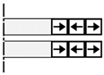 | 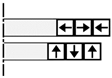 |  |
| Characteristic | AMB | PMB | HMB |
|---|---|---|---|
| Source of force | Electromagnet [33,34] | PM [40,41,42,43] | PM + Electromagnet [46,47] |
| Control system | sensor and active control | Non-active control | Partial active control |
| Power consumption | High (continuous power supply) | 0 | Medium (adjustment only) |
| Stability | Full degree of freedom and stability | Required auxiliary stabilization | Full degree of freedom and stability |
| Typical application | High-precision machine tools [48], aircraft engines | Instrument, simple suspension device [43] | Compressor, flywheel energy storage [49] |
| Nonlinearity | Strong | Medium | Linearization around the operating point |
| Force density | Medium | Low | High |
| Speed range (r/min) | 104~106 | 103~104 | 104~105 |
| Reliability | High (electronic devices limit) | Extremely high (no active parts) | Very high |
| Applications | AMB | PMB | HMB | Technical Selection Basis |
|---|---|---|---|---|
| High-speed precision machining | CNC machine tool spindle [48] | - | Mid-end machine tool [47] | Accuracy and response speed |
| Fluid machinery | Special operating compressor [50] | Micro-flow pump [42] | Centrifugal compressor, blower [51] | Balance of power and efficiency |
| Energy equipment | Flywheel energy storage [52] | - | Wind turbine, fuel cell compressor [45] | Reliability and maintenance |
| Transportation | Maglev train [53] | - | - | Large-scale accurate control |
| Aerospace | Satellite flywheel [54], APU | Simple suspension device [40] | Space actuators [55] | Environmental adaptability |
| Medical device | - | Artificial heart pump [56] | - | Zero power consumption and biological compatibility |
| Technical Limitation | AMB | PMB | HMB | Solutions |
|---|---|---|---|---|
| Cost | Very high (electronic system) | Low-medium | Medium-high | Scale and integration |
| Temperature limit | Medium (electronic devices) | High (PM limit) | Medium | high-temperature materials |
| Stability risk | Control failure | Earnshaw theorem | Medium | Improved protection bearing |
| Force density | Medium | Low | High | Optimize magnetic circuit |
| Standardization | High | Low | Low | Promoting industry standards |
| Typical failure mode | Electronic system failure | PM demagnetization | Electromagnetic under-regulation | Redundancy design |
| Poles | Bearing Capacity | Stiffness | Power | Control Complexity | Typical Application |
|---|---|---|---|---|---|
| 3 poles [57] | Low (micro-rotor) | Low | Medium-high | High | Microsensors, laboratory equipment |
| 4 poles [33] | Medium (medium-small rotor) | Medium | Medium | Medium | Medical equipment, small compressor |
| 6 poles [68] | High (medium rotor) | High | Medium-low | Higher | High-speed centrifuge, CNC machine tool |
| 8 poles [34] | High (medium rotor) | Medium-low | Low | Low | High-speed motor, small flywheel energy storage |
| 12 poles [73] | Medium (medium rotor) | Higher | Medium | Medium | Industrial compressors, medium blowers |
| 16 poles [74] | High (large rotor) | High | High | High | Wind turbine, heavy centrifuge |
| 24/32 poles | Stabilizing (oversized rotor) | Very high | Very high | Very high | Maglev train, nuclear main pump |
| Modeling Methods | Advantage | Disadvantages | Applicable Scene |
|---|---|---|---|
| Equivalent Magnetic Circuit Method [44,77,81,82,83,84,85,86,87] | Computationally efficient, suitable for fast iterative | Ignore flux leakage and nonlinear effects, which require empirical correction | Magnetic bearing with regular magnetic field distribution, preliminary design stage. |
| Maxwell Tensor Method [49,89,90,91,92,93,94,95,96] | High precision, quantifiable current stiffness and eddy current loss. | High computational complexity | AC magnetic bearing, solid rotor |
| Equivalent Magnetic Charge Method [97,98,99,100,101] | Suitable for different magnetization directions, High theoretical accuracy | complex numerical integration model | Analysis of static characteristics of PMB |
| Magnetic Network Method [11] | Balance Efficiency and precision, Support 3D modeling | The error increases when the network is partitioned coarsely | Complex geometric structure, multi-DOF coupling analysis |
| Subdomain Method [102,103,104] | High analytical accuracy | Ignore core saturation | 5-DOF magnetic bearing, multi-pole structure |
| FEM | Highest precision support for multi-physics field coupling | time-consuming, the hardware requirement | Analysis of complex physical field distribution |
| Control Algorithm | Advantages | Limitations | Typical Application |
|---|---|---|---|
| PID control [111] | Simple structure, clear parameters, easy to implement | Difficult to adapt to nonlinearity/time variation, Limited anti-interference | Low-complexity systems (e.g., laboratory demonstration) |
| Variable parameter PID [112] | Adjust parameters dynamically, balancing dynamic response with accuracy. | Complex adjustment rules real-time performance is limited | Startup phase or set point changes frequently |
| Robust control [129] | Parameters and perturbations insensitive, multivariate coupling. | Relying on accurate models, high computational complexity, dynamic performance is limited | High-precision machine tools, aerospace flywheels, and strong interference environments. |
| Predictive control [132] | Predict the future state based on the model and adapt to nonlinear/time-varying systems. | Large computation, error sensitive, update frequently | Dynamic, high-speed response, multi-target coordination |
| Sliding-mode control [135] | Strong robustness, quick response, parameter insensitive | Chattering requiring higher-order precise sliding mode design or adaptive control | High anti-interference (e.g., flywheel energy storage) |
| Neural network control [139] | No need for an accurate mathematical model; online learning | Amount of training data, computationally intensive, poor interpretability | Adaptive adjustment of complex operating (e.g., variable load) |
| Adaptive control [54] | Automatically adjust parameters to improve robustness. | Slow convergence speed adaptability to fast time-varying systems is limited. | System with parameters changing slowly (e.g., compressor) |
| Fuzzy control [53] | Dynamically adjust parameters, no need for accurate models, anti-interference. | Rule design relies on experience; parameter tuning is complex, and high-frequency accuracy is insufficient. | Strong nonlinearity and unclear model (e.g., medical devices) |
| Topology | Switches | Diodes | Drive Power | Voltage Utilization |
|---|---|---|---|---|
| Full bridge [148] | 8N | 8N | 4N + 1 | 1 |
| Half bridge [149] | 4N | 4N | 2N + 1 | 1 |
| Three-phase full bridge [151] | 6N | 6N | 3N + 1 | 0.5 |
| Three-phase half bridge [152] | 3N | 3N | N + 1 | 0.5 |
| Shared bridge [153] | 2N + 1 | 2N + 1 | 2 | 0.5 |
| Reverse shared bridge [154] | 2N + 2 | 2N + 2 | 3 | 0.5 |
| Series coils [155] | 2N + 1 | 2N + 1 | N + 1 | 1 |
| Hardware Types | Advantage | Disadvantages | Applicable Scene |
|---|---|---|---|
| STM32 series [157] | Low power consumption, low cost, short development cycle, easy to control | Limited computing power and limited real-time performance | Low complexity scenarios such as medium and low speed, single/two DOF. |
| DSP [158,159] | High real-time performance, support for complex algorithms | Relying on special development tools, high power consumption | High-speed, multiple DOF and other high-precision scenes |
| FPGA [160,161] | Strong real-time performance | Long development cycle, high cost | Ultra-high-speed and complex algorithm scenarios. |
| Machine Type | 5.8 MW Centrifugal Compressor with Canned Electric Motor |
|---|---|
| Speed range | 2850~9975 r/min continuously variable |
| Rotor mass | 1622 kg |
| Rotor length | 3.3 m |
| Rotor orientation | Vertical |
| AMB configuration | Single shaft, 2 radial and 1 axial. |
| Machine Type | 10 kW Industrial Grade AMB High-Speed Spindle |
|---|---|
| Speed range | 0~50,000 r/min continuously variable |
| Static load | 3.2 kg |
| Tracking range | 90 μm |
| Rotor orientation | Horizontal |
| AMB configuration | Single shaft, 2 radial and 1 axial. |
| Machine Type | 100 kW Energy Storage Flywheels |
|---|---|
| Speed range | 3225 r/min |
| Rotor mass | 5440 kg |
| Outer diameter | 2.13 m |
| Rotor orientation | Vertical |
| AMB configuration | Single shaft, combination 5-DOF AMB. |
| Machine Type | Small Scale Vertical Axis Wind Turbine |
|---|---|
| Speed range | 200 r/min |
| Maximum repelling force | 124 N |
| Outer diameter | 500 mm |
| Rotor orientation | Vertical |
| AMB configuration | Single shaft, PMB. |
| Machine Type | Magnetically Suspended Control Moment Gyros |
|---|---|
| Stable operating frequency | 100 Hz |
| Rotor mass | 16.7 kg |
| Outer diameter | 250 mm |
| Rotor orientation | Vertical |
| AMB configuration | Single shaft, 2 radial and 1 axial. |
| Machine Type | Centrifugal Helium Circulator |
|---|---|
| Speed range | 800~4800 r/min continuously variable |
| Rotor mass | 4000 kg |
| Rotor length | 3.5 m |
| Rotor orientation | Vertical |
| AMB configuration | Single shaft, 2 radial and 1 axial. |
Disclaimer/Publisher’s Note: The statements, opinions and data contained in all publications are solely those of the individual author(s) and contributor(s) and not of MDPI and/or the editor(s). MDPI and/or the editor(s) disclaim responsibility for any injury to people or property resulting from any ideas, methods, instructions or products referred to in the content. |
© 2025 by the authors. Licensee MDPI, Basel, Switzerland. This article is an open access article distributed under the terms and conditions of the Creative Commons Attribution (CC BY) license (https://creativecommons.org/licenses/by/4.0/).
Share and Cite
Du, Y.; Zhang, G.; Hua, W. Review on Research and Development of Magnetic Bearings. Energies 2025, 18, 3222. https://doi.org/10.3390/en18123222
Du Y, Zhang G, Hua W. Review on Research and Development of Magnetic Bearings. Energies. 2025; 18(12):3222. https://doi.org/10.3390/en18123222
Chicago/Turabian StyleDu, Yuanhao, Gan Zhang, and Wei Hua. 2025. "Review on Research and Development of Magnetic Bearings" Energies 18, no. 12: 3222. https://doi.org/10.3390/en18123222
APA StyleDu, Y., Zhang, G., & Hua, W. (2025). Review on Research and Development of Magnetic Bearings. Energies, 18(12), 3222. https://doi.org/10.3390/en18123222