1. Introduction
At the level of motor design, the requirements for high torque density and wide speed range imposed by electric drive applications are typically addressed by adopting rotor-embedded permanent magnet configurations to enhance the saliency ratio (
Lq/
Ld). For instance, traction motors for electric vehicles predominantly employ high-saliency-ratio designs [
1,
2,
3,
4,
5,
6,
7]. This design philosophy can also be extended to five-phase motors intended for electric drives to satisfy their torque density and extended operational speed demands. Furthermore, the increased saliency ratio implies that the contribution of reluctance torque to the total output torque becomes non-negligible. Consequently, control strategies must be refined to effectively leverage the additional reluctance torque component, ensuring optimal utilization of both permanent magnet and reluctance torque mechanisms [
8].
In the control of three-phase salient-pole permanent magnet synchronous motors (PMSMs), Maximum Torque Per Ampere (MTPA) control is commonly employed for sub-base-speed operation [
9,
10]. This strategy enables the motor to either maximize torque output under a given current amplitude or minimize stator winding current while maintaining equivalent torque output. These two objectives are equivalent, with the latter formulation aligning more closely with conventional optimization paradigms. Following this methodology, the discussion on MTPA control strategies for five-phase salient-pole PMSMs in this chapter retains the core principle: identifying the minimum stator current magnitude under specified torque output requirements [
11]. The analytical framework thereby prioritizes current minimization as the optimization criterion, ensuring efficient utilization of both reluctance torque and permanent magnet torque components inherent to high-saliency-ratio motor designs [
12,
13].
Extensive research has been conducted on Maximum Torque Per Ampere (MTPA) control strategies for three-phase motors. Theoretically, this control can be achieved by deriving MTPA current references from torque equations based on torque commands, implemented through real-time computation or lookup table methods [
14]. However, in practical operating conditions where motor parameters vary with operating temperatures and saturation levels, such parameter-dependent strategies often fail to achieve optimal control performance. While experimental calibration of MTPA current references eliminates theoretical dependencies, it requires per-unit testing and remains susceptible to accuracy degradation caused by temperature-induced parameter variations during operation [
15,
16,
17].
Real-time search methods, which dynamically identify MTPA operating points without relying on motor parameters, employ stepwise perturbation to track optimal conditions [
18,
19]. Although parameter-independent, these methods exhibit slow convergence rates due to incremental adjustments, leading to compromised dynamic performance under rapid torque transients. High-frequency signal injection methods, a subset of search-based approaches, achieve faster tracking by injecting high-frequency perturbations into stator currents and adjusting current vectors based on torque ripple responses. This technique enhances convergence speed but necessitates high-bandwidth torque measurement systems with stringent accuracy requirements. In contrast, virtual signal injection methods computationally emulate perturbation effects to regulate currents, sacrificing partial parameter independence to reduce hardware complexity while maintaining acceptable dynamic responsiveness [
20].
Five-phase motors with third harmonic back-electromotive force (EMF) can adopt the same Maximum Torque Per Ampere (MTPA) control strategy as three-phase permanent magnet motors through field-oriented vector control, thereby achieving MTPA operating point tracking [
7,
13]. However, the increased phase number necessitates harmonic subspace vector control in the vector framework. Implementing MTPA solely in the fundamental subspace neglects reluctance torque contributions from the harmonic subspace, compromising optimal MTPA performance [
16]. When harmonic current vector control is integrated into the MTPA strategy, the following modifications arise: (1) Analytical formulations still provide MTPA current references for both fundamental and harmonic subspaces but remain heavily dependent on motor parameters; (2) experimental calibration of MTPA current references becomes significantly more complex due to the requirement for simultaneous testing of fundamental and harmonic subspace currents; (3) search-based methods suffer from mutual interference between fundamental and harmonic torque components during concurrent optimization, while sequential optimization (fundamental followed by harmonic) degrades dynamic tracking performance; (4) high-frequency signal injection requires dual-frequency high-frequency signal injection in the fundamental and harmonic subspaces instead of a single-frequency approach, demanding higher accuracy and speed in torque measurement; (5) virtual signal injection enables MTPA tracking for both current vectors via computational emulation of perturbation effects on fundamental and harmonic currents [
19].
This paper proposes a multi-dimensional MTPA (Maximum Torque Per Ampere) control strategy based on virtual signal injection for salient-pole five-phase permanent magnet synchronous motors (PMSMs) with harmonic components, aiming to enhance mechanical performance metrics and current utilization efficiency during sub-rated speed operation. Firstly, a mathematical model of the salient-pole five-phase PMSM incorporating harmonic effects is established, including its representation in the synchronous reference frame, to construct a field-oriented vector control framework. Subsequently, theoretical MTPA current references are derived based on output torque requirements, providing explicit formulations for both fundamental-wave-only and harmonic-inclusive scenarios. Furthermore, the virtual signal injection method is analyzed for MTPA control in the fundamental subspace and extended to the harmonic subspace, thereby establishing a comprehensive multi-subspace MTPA strategy. Finally, simulations and experimental tests validate the effectiveness of the proposed control methodology.
2. FP-PMSM Modeling
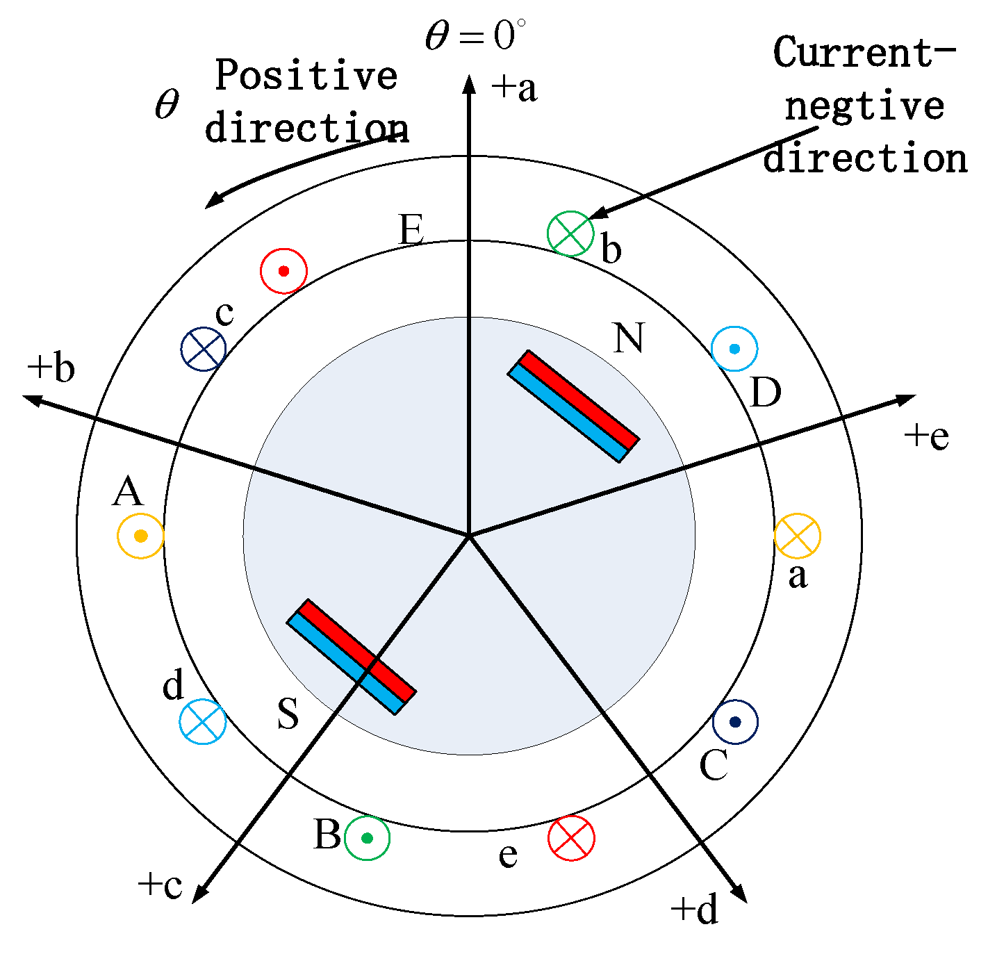
The five-phase interior permanent magnet synchronous motor (IPMSM) studied in this paper is structurally simplified as shown in the figure below. As shown in
Figure 1, with the axis of phase A winding as the origin, subsequent phases are uniformly distributed counterclockwise, each separated by
δ = 72° electrical angle. To facilitate analysis, the following simplifying assumptions are made:
(1) The stator windings and permanent magnet flux linkages contain only fundamental and third harmonic components, neglecting the influence of other harmonic orders.
(2) The motor exhibits linear magnetic circuit characteristics, disregarding the effects of core saturation, hysteresis, and eddy current losses.
(3) Stator slotting effects are ignored, and no damper winding exists on the rotor.
2.1. Natural Coordinate Motor Model
Under the natural coordinate system, the mathematical model of a five-phase permanent magnet motor serves as the foundation for understanding its operational principles and performance characteristics. This model typically encompasses parameters such as inductance, resistance, and magnetic flux linkage, which can be obtained through experimental measurements or theoretical calculations. The natural coordinate system-based formulation directly reflects the motor’s physical attributes, providing critical insights for comprehending and analyzing its electromechanical behavior.
The voltage equations in the natural coordinate system for a salient-pole five-phase permanent magnet synchronous motor (PMSM) with harmonics are expressed as follows, with all physical quantities defined according to the motor convention:
And the
Us = [
ua ub uc ud ue]
T is stator voltage;
Is = [
ia ib ic id ie]
T is stator voltage;
Rs is stator winding resistance. Ignore the phase disequilibrium:
The stator flux equation is as follows:
The stator flux linkage comprises two components: the permanent magnet flux linkage linked to the stator side and the flux linkage generated by the stator currents. The permanent magnet flux linkage, incorporating the third harmonic component, can be expressed as follows:
ψf1 and
ψf3 are base-wave third harmonic permanent magnet flux amplitude;
θe is rotor electrical angle and
Stator current generates flux linkage
LsIs as follows:
The matrix represents the stator inductance matrix, where the diagonal elements correspond to the self-inductance of each phase winding, while the off-diagonal elements denote the mutual inductance between phases. For the five-phase motor under study, the interior permanent magnet rotor configuration introduces position-dependent mutual inductance due to the non-uniform radial permeability distribution caused by the embedded magnets.
where
Lls is stator leakage,
Llm is a constant quantity in mutual inductance that does not depend on rotor position,
L is the amount of fluctuation associated with the rotor in mutual inductance, the rate of change is twice the angular frequency of the rotor.
The electromagnetic torque of the motor is derived from the virtual displacement method by deflecting the magnetic common energy to the rotor position angle:
where
θm is rotor mechanical position angle;
np is number of motor poles; and
θe =
npθm.
The motor motion equation is as follows:
where
Jm is the moment of inertia;
ωm is rotor mechanical angular velocity;
TL is rotor mechanical angular velocity; and
Bm is damping coefficient.
As demonstrated, the mathematical model of a salient-pole five-phase permanent magnet synchronous motor (PMSM) with harmonic back-EMF in the natural coordinate system exhibits nonlinearity and strong coupling characteristics. These couplings manifest in interactions among inter-phase flux linkage, rotor position, and stator inductance, rendering the model unsuitable for direct application in motor control system analysis and regulation. To achieve precise control of the target motor and attain control performance comparable to DC motors, decoupling transformations of the physical quantities are essential.
2.2. Synchronous Coordinate Motor Modeling
The synchronous reference frame model is derived by transforming the mathematical model of the five-phase permanent magnet motor through coordinate transformations. Decoupling is achieved via an extended Clarke transformation that maps the physical quantities of each phase into two stationary orthogonal subspaces and a generalized zero-sequence subspace, with the transformation defined as follows:
The coefficient 0.4 ensures amplitude invariance during the transformation. The fundamental components of the physical quantities are mapped to the α1–β1 subspace via the first two rows of the transformation matrix, while the third-harmonic components are projected onto the α3–β3 subspace through the third and fourth rows. Currents in both subspaces generate stable rotating magnetomotive forces (MMFs) in the air gap, with the α3–β3 subspace MMF rotating at three times the speed of the α1–β1 subspace. Furthermore, fifth-harmonic components are directed to the zero-sequence subspace via the fifth row, where they manifest as pulsating components in the air gap that do not contribute to electromechanical energy conversion.
The three stationary subspaces are mapped into the synchronous rotating reference frame using the extended five-phase Park transformation matrix. By neglecting coupling effects between subspace, the transformation matrix is expressed as follows:
Then, the transformation matrix of the five-phase motor under the natural coordinate system to the synchronous rotating coordinate system is as follows:
The motor voltage equation has been transformed
where
Speed matrix Ω
dq is as follows:
From Equation (14), the flux linkage equation in synchronous rotating coordinate system can be written as follows:
where the stator inductance matrix is as follows:
The permanent magnet flux linkage transformation in synchronous coordinate system is as follows:
Substituted into Equation (17), the zero sequence component is omitted, then the voltage and current equation of a five-phase motor in a synchronous rotating coordinate system is as follows:
where
ud1,
uq1,
ud3, and
uq3 are the stator voltage of the fundamental wave and the third harmonic,
Is,
I1, and
I3 are the amplitude of the total stator winding current and the base wave third harmonic current,
θ1, and
θ3 are the angle between the fundamental and harmonic current vectors and the positive direction of the d-axis in their respective synchronous coordinate systems. Electromagnetic torque of the motor is as follows:
The equation of motion is as follows:
As evident from the above equation, the output torque of a salient-pole five-phase permanent magnet synchronous motor (PMSM) with harmonics comprises both permanent magnet (PM) torque and reluctance torque in the fundamental plane, as well as PM torque and reluctance torque in the harmonic plane. The reluctance torque contributions from both fundamental and harmonic planes can be leveraged to enhance the motor’s overall torque output.
3. Control Strategy Design
3.1. Double Space Vector Control
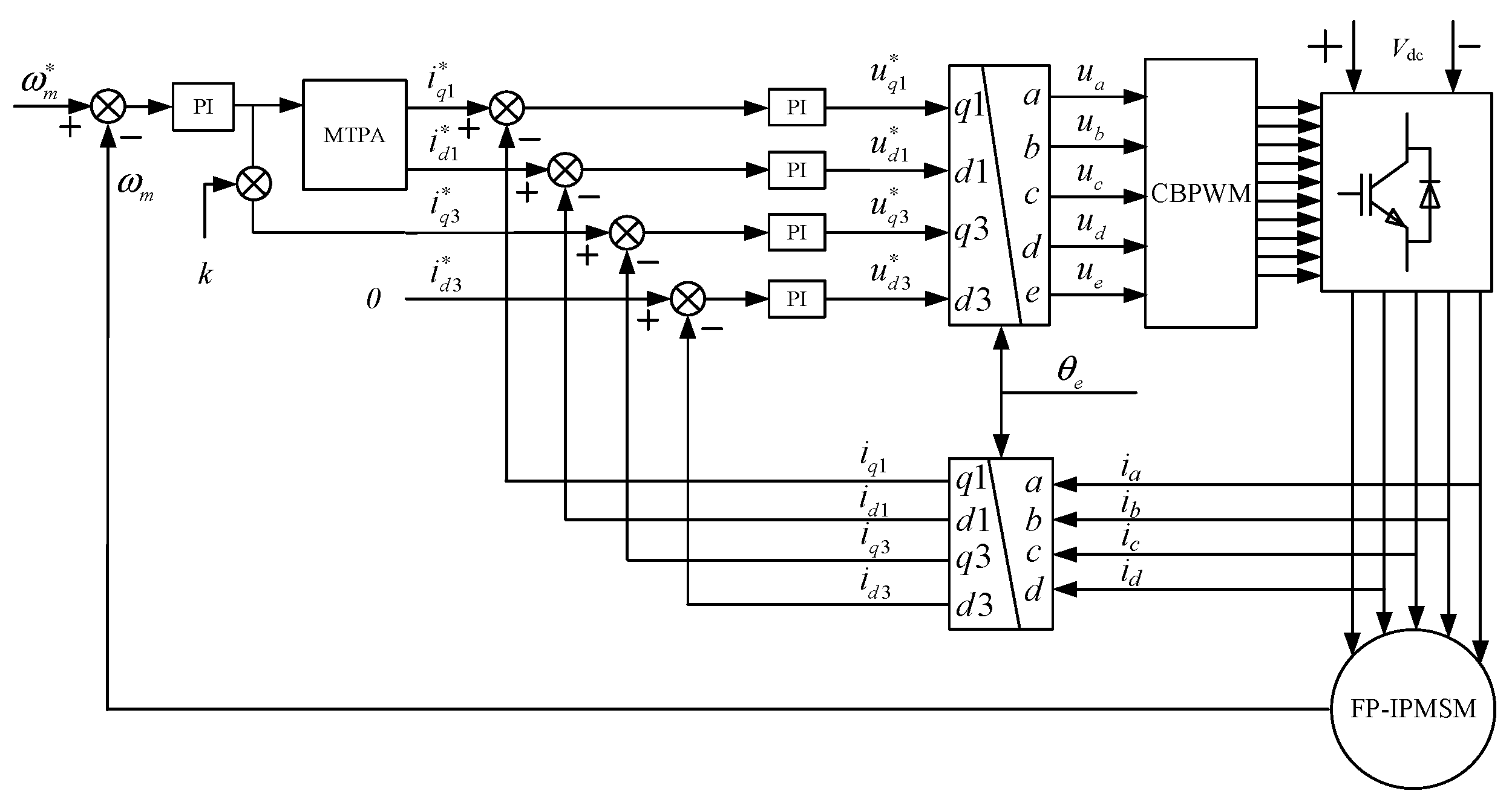
In control strategies considering both fundamental and third harmonic planes, the fundamental and third harmonic components of the motor must be simultaneously addressed. While the associated mathematical formulations become more intricate under such conditions, enhanced control precision can be achieved. As illustrated in
Figure 2, the injected harmonic currents are exclusively quadrature-axis components
iq3, where k denotes the third harmonic torque distribution coefficient. Setting
k = 0 suppresses third harmonic plane currents to minimize harmonic torque, suitable for scenarios requiring reduced stator current harmonic distortion or where third harmonic torque contribution is negligible. As derived in Equation (20), the third harmonic quadrature-axis current interacts with the third harmonic permanent magnet flux linkage to generate stable torque. Therefore, selecting
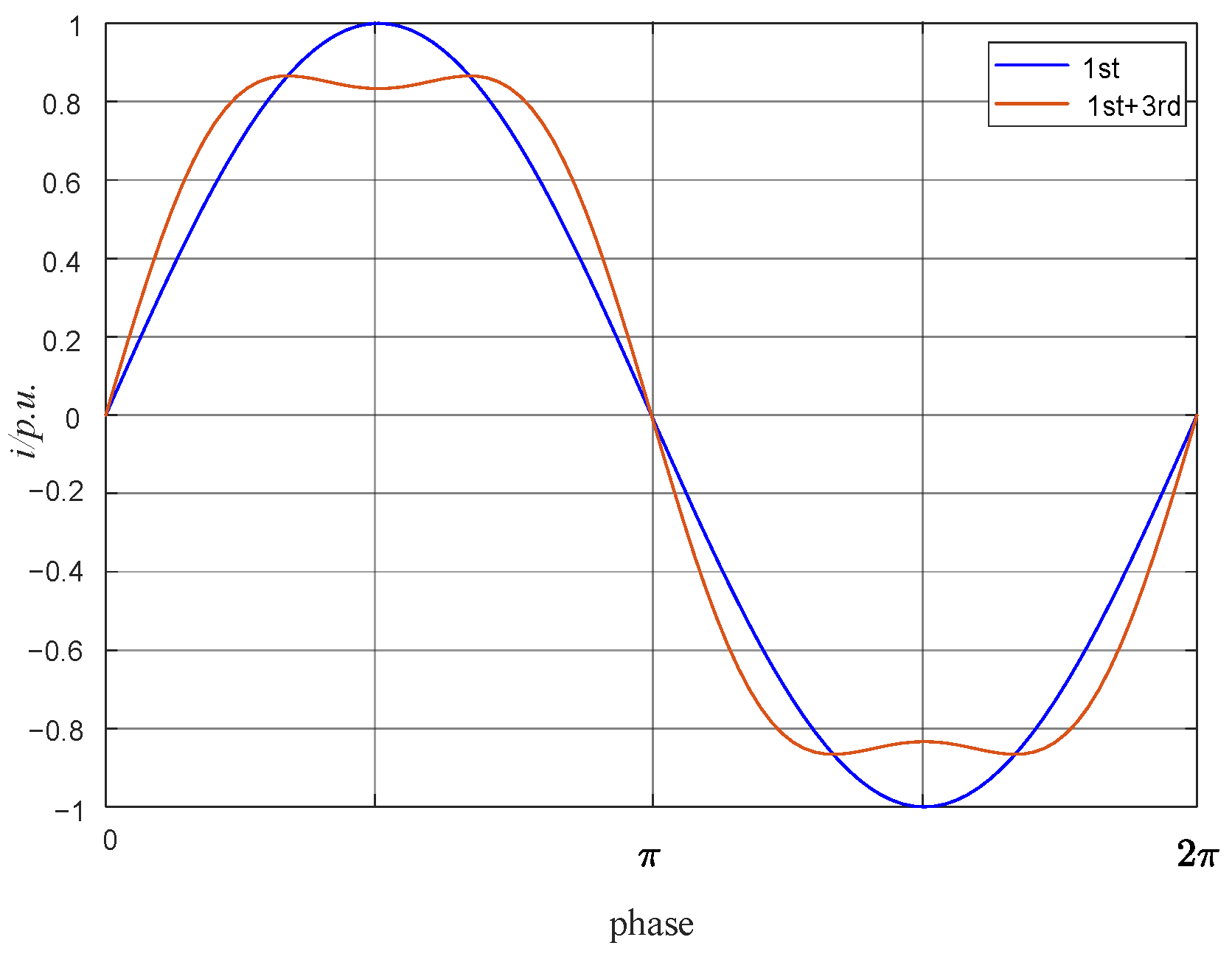
k > 0 in the control strategy enables intentional injection of third harmonic currents, yielding additional stable harmonic torque output. The corresponding stator current waveforms under this condition are depicted in
Figure 2.
The selection of
k depends on the magnitudes of the harmonic permanent magnet flux linkage
ψf3, fundamental permanent magnet flux linkage
ψf1, and stator current constraints. For simplified implementation,
k is typically determined based on the ratio between the fundamental and third harmonic components of the permanent magnet flux linkage, expressed as follows:
Furthermore, setting
k < 0 induces negative torque generation in the harmonic plane, which degrades motor efficiency and is generally avoided. Compared to single space vector control, the dual space vector control strategy incorporates closed-loop regulation of both d-axis and q-axis currents in the third harmonic plane. This eliminates the inherent limitation of single space vector control, where even minor harmonic magnetomotive forces generate substantial uncontrolled harmonic currents due to the low harmonic inductance as shown in
Figure 3.
3.2. Analytical Formulation of Dual-Subspace MTPA Control
3.2.1. Only Fundamental Wave
When the harmonic injection coefficient
k = 0, harmonic currents are suppressed. According to Equations (20) and (24), the motor’s voltage and torque equations under this condition reduce to:
Identical to the single-space control structure, the MTPA control strategy can therefore be directly applied from the previous section, yielding a virtual signal injection-based MTPA control method under dual-space harmonic suppression conditions. The corresponding control architecture is illustrated in
Figure 4.
Compared to the single-subspace MTPA control strategy, the harmonic-suppressed dual-subspace fundamental MTPA control eliminates uncontrolled harmonic currents caused by non-zero harmonic magnetomotive forces (MMFs), thereby avoiding adverse effects on motor torque output. This approach exhibits enhanced adaptability over conventional single-subspace control architectures.
3.2.2. Fundamental Combined Harmonics
When the harmonic injection coefficient
k > 0, the quadrature-axis current
iq3 in the third harmonic plane is injected into the stator windings by the current controller. As indicated by Equation (24), this configuration generates stable permanent magnet torque in the harmonic plane, thereby enhancing the motor’s overall torque output capability. By analogy with the MTPA control methodology for the fundamental plane discussed in the preceding section, the dual-subspace control strategy is extended to incorporate harmonic plane optimization. Under this condition, the stator current is expressed as follows:
Considering the quadrature axis current component injected into the third harmonic plane, the motor torque equation at this time is as follows:
Due to the additional torque contribution from the harmonic plane, the MTPA operating point differs from that under the single-space control structure, necessitating separate analysis. When determining
θ1MTPA for the fundamental plane under single-space control conditions, the resulting
θ1MTPA in the fundamental plane is obtained as follows:
The contribution of third-harmonic current injection to the total current amplitude also influences the overall MTPA effectiveness, therefore necessitating the determination of an optimal third-harmonic injection ratio k under these conditions. This MTPA optimization framework is decomposed into two subproblems: (1) MTPA tracking control in the fundamental plane, implemented identically to the methodology described in the preceding section; (2) regulation of the third-harmonic injection ratio
k, which aims to maximize Equation (30). Subject to inverter capacity limitations and motor current thermal constraints, the optimization is performed under the condition that the RMS value of the total current remains invariant before and after harmonic injection, expressed as follows:
where
I10 denotes the fundamental current prior to third-harmonic injection. The introduction of harmonic currents reduces the fundamental component in the stator current. To achieve net torque enhancement, the torque contribution from the third harmonic must exceed the torque reduction caused by diminished fundamental components. By combining Equations (30) and (31), the optimal third-harmonic current injection ratio for maximum output torque is determined through the Lagrange multiplier method. It is determined as follows:
Under the constant RMS current constraint, the optimal injection ratio
k that maximizes output torque is determined by the ratio between third harmonic and fundamental components in the permanent magnet flux linkage, fundamental d-q-axis inductances (
Ld1,
Lq1) and the fundamental current angle
θ1. With MTPA control implementation,
θ1 ultimately converges to
θ1MTPA. Notably, when
Ld1 =
Lq1 (i.e., in non-salient-pole machines), the MTPA control becomes equivalent to
Id1 = 0 control, where sin
θ1 = 1. Under this condition, Equation (33) degenerates into the empirical Equation (30), representing the optimal current injection ratio for five-phase non-salient-pole PMSMs. Consequently, the virtual signal injection-based MTPA tracking control for salient-pole five-phase PMSM with third harmonic q-axis current injection is established. As depicted in
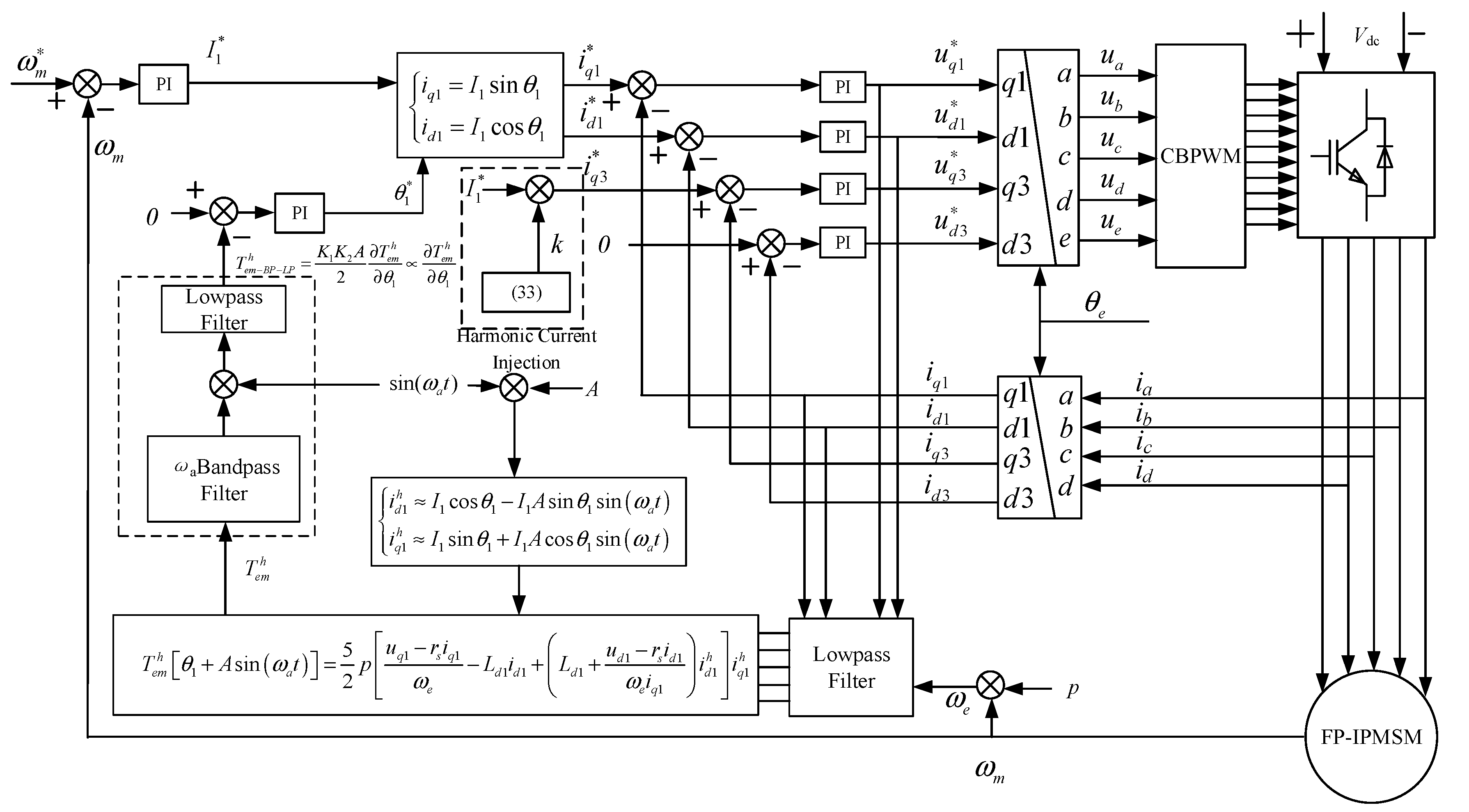
Figure 5, the fundamental MTPA control module replicates the structure from the preceding section, while the third harmonic q-axis current injection component is calculated via Equation (33).
3.3. Signal Injection of Dual Spatial Plane MTPA Control
3.3.1. Only Fundamental Signal Injection
As indicated by Equation (24), the fundamental and harmonic planes are decoupled under dual-space vector control, with the fundamental plane equations remaining identical to those under single-space vector control. Therefore, the virtual signal injection-based MTPA control methodology established in previous work can be directly applied to the dual-space vector control framework, thus precluding the need for redundant elaboration.
3.3.2. Fundamental Wave MTPA and Harmonic MTPA Signal Injection
As derived from Equation (24), stable torque output can be achieved by injecting controlled third-harmonic currents into the stator windings. As established in the preceding section, the optimal third-harmonic current injection for a salient-pole five-phase PMSM with harmonic components is given by Equation (30), where the theoretical calculation of fundamental MTPA and its tracking via virtual signal injection remain unaffected by third-harmonic current injection levels. Similarly to the fundamental plane, the harmonic plane torque comprises both permanent magnet torque and reluctance torque components. This implies that under constant total current magnitude in the harmonic plane, MTPA control can be implemented to maximize the harmonic plane torque output.
Equation Calculation
Under the condition of fixed output torque, Equation (24) is translated into the fundamental current
I1 and the third harmonic current
I3, and the current angles
θ1 and
θ3 are as follows:
By minimizing the current magnitudes for both fundamental and third harmonic components in the above equation, the current angles corresponding to the MTPA operating point can be derived as follows:
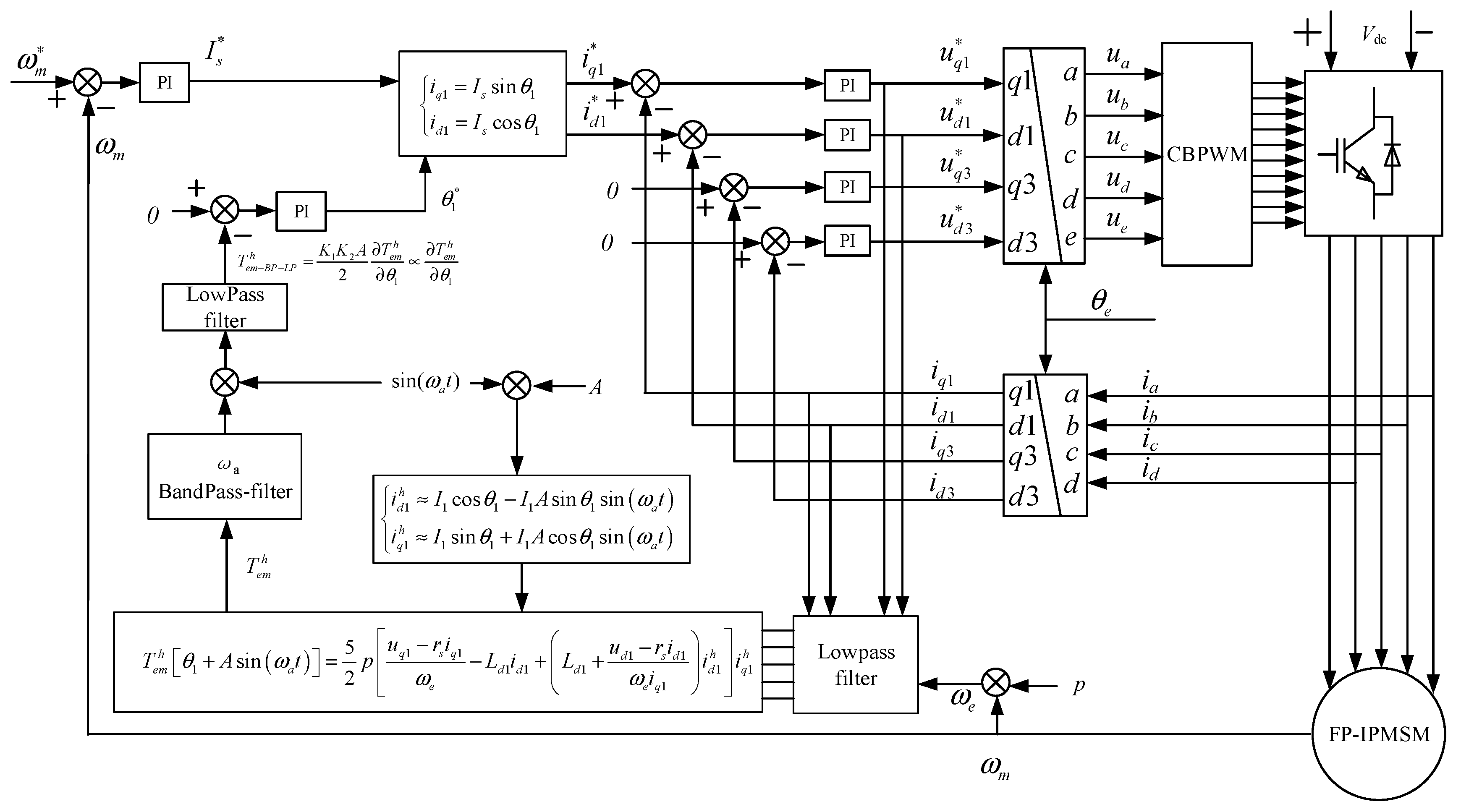
As shown in
Figure 6, then the five-phase PMSM biplanar MTPA control method calculated according to the formula can be obtained, and its control block diagram is shown as follows. Where the speed loop outputs the fundamental current command value
I1*,
k is the injection ratio of the third harmonic current, and the optimal injection value is the third harmonic current
I3* according to Equation (35).
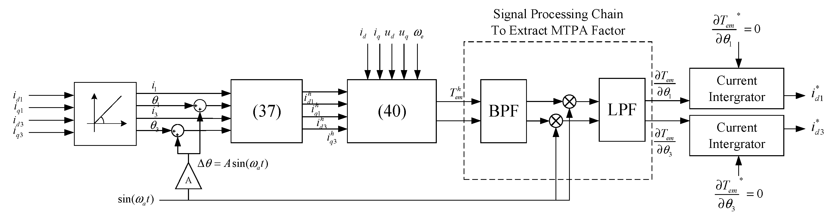
Virtual Signal Injection
For the motor at the MTPA operating point, the angle between the dq plane current synthesis vector and the positive direction of the d axis is θMTPA, Partial derivative of electromagnetic torque Tem and current angle θ is ∂Tem/∂θ < 0. When the current angle is less than θMTPA, ∂Tem/∂θ > 0. When the current angle is more than θMTPA, (∂Tem)/∂θ < 0.
The MTPA control strategy based on virtual signal injection is divided into the following steps:
① Generation of virtual injection signal. A small disturbance angle is applied to the base-wave harmonic current angle, i.e.,
Then, the injected current can be approximated by the following formula:
② The fundamental plane and harmonic plane are injected in virtual mode, respectively. The current in the formula is replaced with the current after harmonic injection, as follows:
③ Based on the voltage equation of the five-phase PMSM in the synchronous coordinate system, replacing motor parameters with operating state parameters yields:
Substituting Equations (38) and (39) yields:
The electromagnetic torque is calculated following virtual signal injection to extract the MTPA factor.
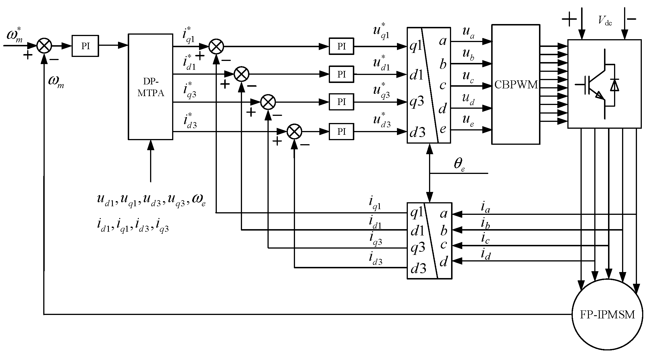
4. Simulation and Experimental Results
The dual-plane MTPA control structure is shown in
Figure 7, while the overall vector control simulation of the five-phase motor as shown in
Figure 8 is built, and the parameters of the five-phase permanent magnet motor are shown in
Table 1.
Figure 9 is the actual diagram corresponding to
Figure 7.
4.1. Selection of Simulation Parameters
4.1.1. Selection of Virtual Injection Signal Parameters
① Selection of Signal Amplitude A: The MTPA factor is proportional to the product of electromagnetic torque and the injected signal amplitude. Therefore, increasing the signal amplitude enhances the tracking precision of the signal injection-based MTPA method. In practical implementations, excessive amplitude introduces significant torque ripple, degrading operational efficiency, while insufficient amplitude prevents torque sensors from detecting valid signals, thereby reducing tracking accuracy. For virtual signal injection, however, since no physical high-frequency signals are injected into the windings, a relatively larger amplitude can be selected to ensure precision without inducing adverse torque fluctuations.
② Selection of Signal Frequency ωa: Higher signal frequencies improve control loop dynamics by reducing latency and enhancing system responsiveness, thereby facilitating rapid MTPA point tracking. However, given the discrete nature of motor controllers, excessively high frequencies reduce the number of sampling points per signal cycle, amplifying quantization and computational errors. A lower frequency is generally preferred. Considering the controller’s 10 kHz sampling rate, ωa is selected within 100–500 Hz to ensure at least 20 sampling points per cycle for reliable signal reconstruction. Given the target motor’s low-speed operation, 200 Hz is adopted as the optimal trade-off between tracking agility and signal integrity.
4.1.2. Filter Selection and Parameter Calculation
Figure 7 illustrate the signal processing chain for post-injection torque signals, which incorporates a bandpass filter and a low-pass filter. The bandpass filter is centered at the injection frequency
ωa = 200 Hz. Given computational constraints of the motor controller, second-order filters are adopted for practical implementation. The second-order bandpass filter exhibits an attenuation rate of 40 dB/decade outside its center frequency, while the second-order low-pass filter achieves 40 dB/decade attenuation beyond its cutoff frequency. Since an attenuation exceeding 20 dB is typically deemed sufficient for effective signal suppression, and considering the low-pass filter must attenuate second-harmonic components of the injection frequency (2
ωa), the cutoff frequency is conservatively set to 50 Hz (below the theoretical maximum of 0.4
ωa = 80 Hz) to ensure robust signal conditioning.
The expression of the transfer function of the second-order bandpass filter is as follows:
where
ωn is the central frequency of the filter, here
ωn =
ωa = 200 Hz.
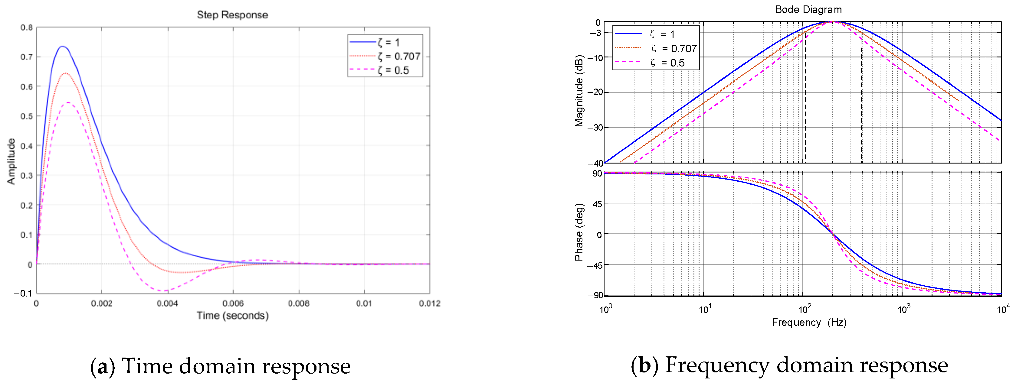
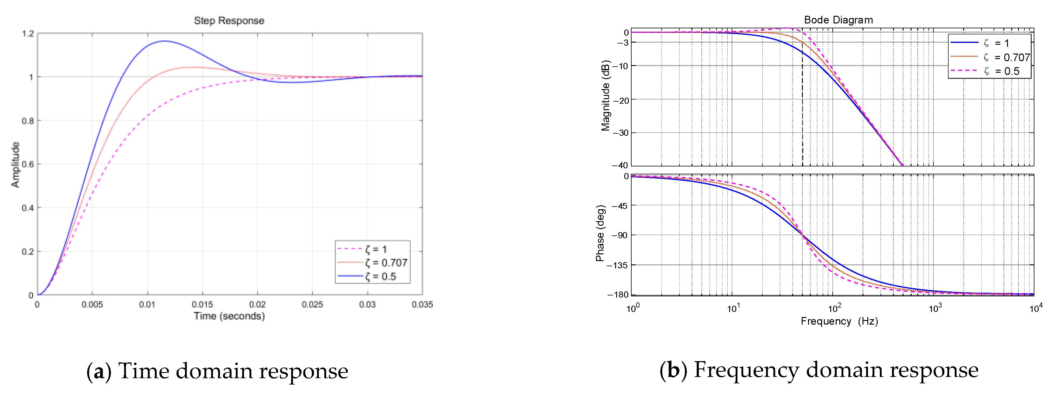
ζ is the damping ratio, which not only affects the steepness of the transition between the passband and stopband in the amplitude–frequency characteristic of the filter but also affects the response speed of the filter.
Figure 10 shows the unit step response and Bode diagram for
ζ at 0.5, 0.707, and 1. In order to take into account the filtering effect and the response stability speed, the damping ratio takes an empirical value
ζ = 0.707, the passband width is 240 Hz, and the response stability time is 0.008 s.
Similarly, the second-order low-pass filter transfer function is expressed as follows:
where
ωn = 50 Hz is the filter cutoff frequency and
ζ is the damping ratio. As shown in
Figure 11, the unit step response and bode diagram are presented for
ζ at 0.5, 0.707, and 1. When
ζ = 0.707, the step response speed and overshoot of the filter are in a reasonable range; the response time is 0.025 s; and the cutoff frequency (−3 dB) is also 50 Hz.
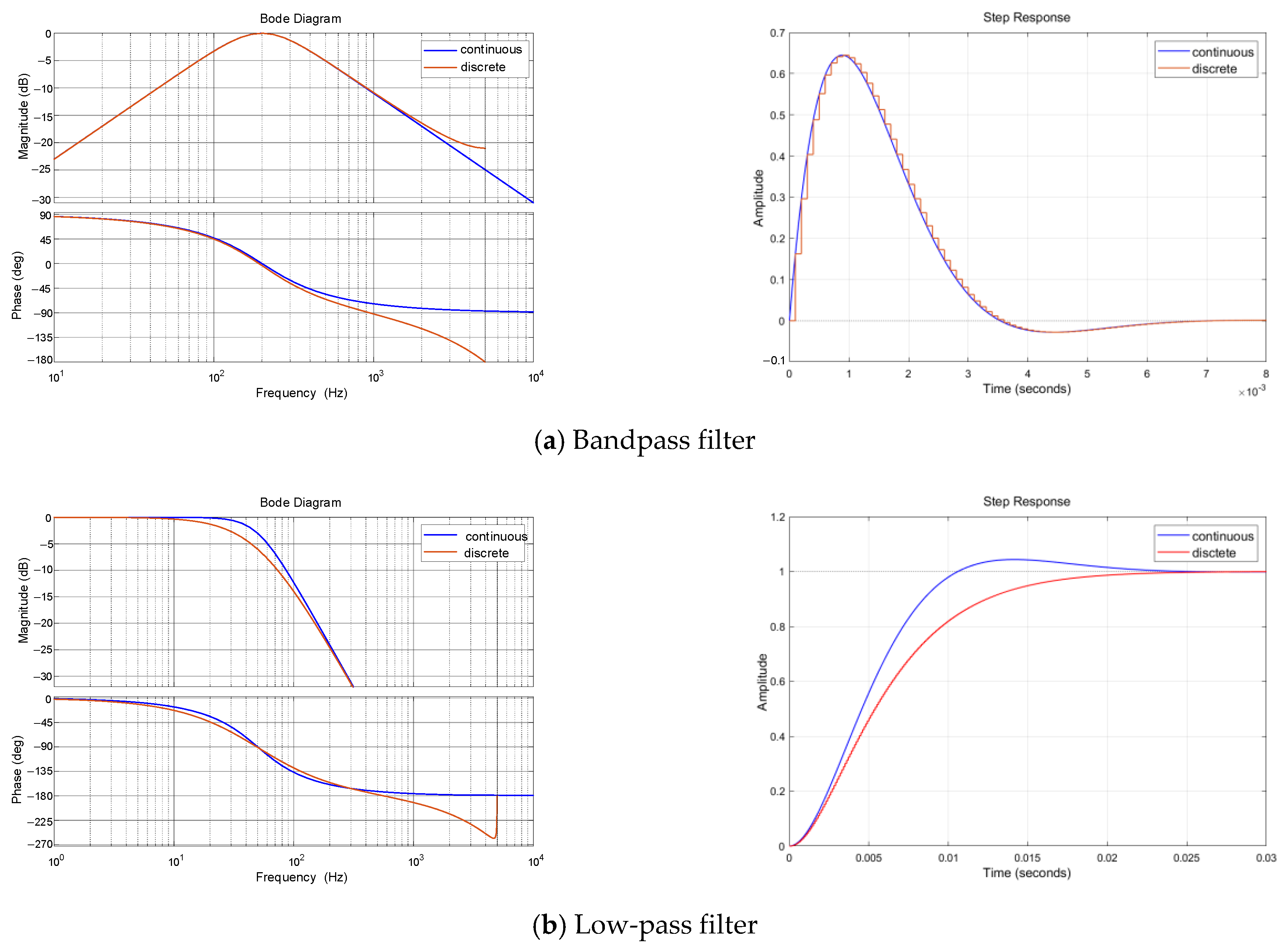
To derive the difference equations for the discrete digital filter implemented in the controller, the zero order hold (ZOH) method is employed for discretization.
Figure 12 compares the Bode plots and step responses of the continuous and discretized filters. The discretized filters exhibit more pronounced phase lag in the high-frequency range compared to their continuous counterparts, as evidenced by the Bode plots. However, the 180° phase lag points remain within the stopband of the filters, ensuring that stability is uncompromised.
4.2. Experiment of Double Space Vector Control Strategy
Build the simulation according to
Figure 7 and the working conditions are the same as those in the previous section.
Id1 = 0 control mode with harmonic current suppression of
I3 = 0 as the target is used as the control group of dual-space vector MTPA control.
Figure 13 shows the phase current waveform and space current size.
As can be seen from the above figure, the uncontrolled third harmonic current under the double space vector control structure is suppressed, and the THD is less than 1%. At the same time, the negative torque generated by the uncontrolled harmonic current is also suppressed, and the amplitude of the fundamental current component under the two groups of loads is also reduced by about 1%, as shown in
Figure 14.
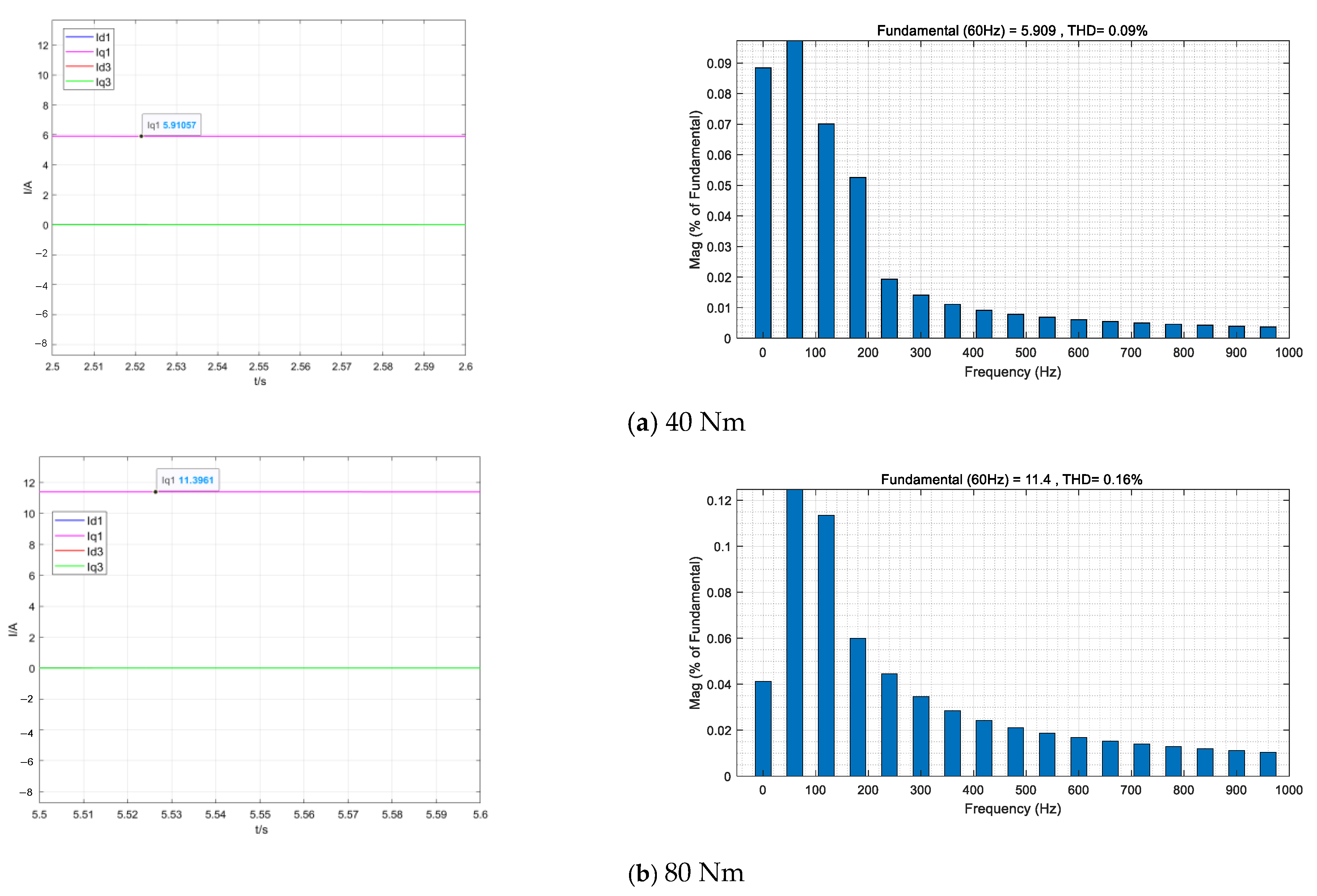
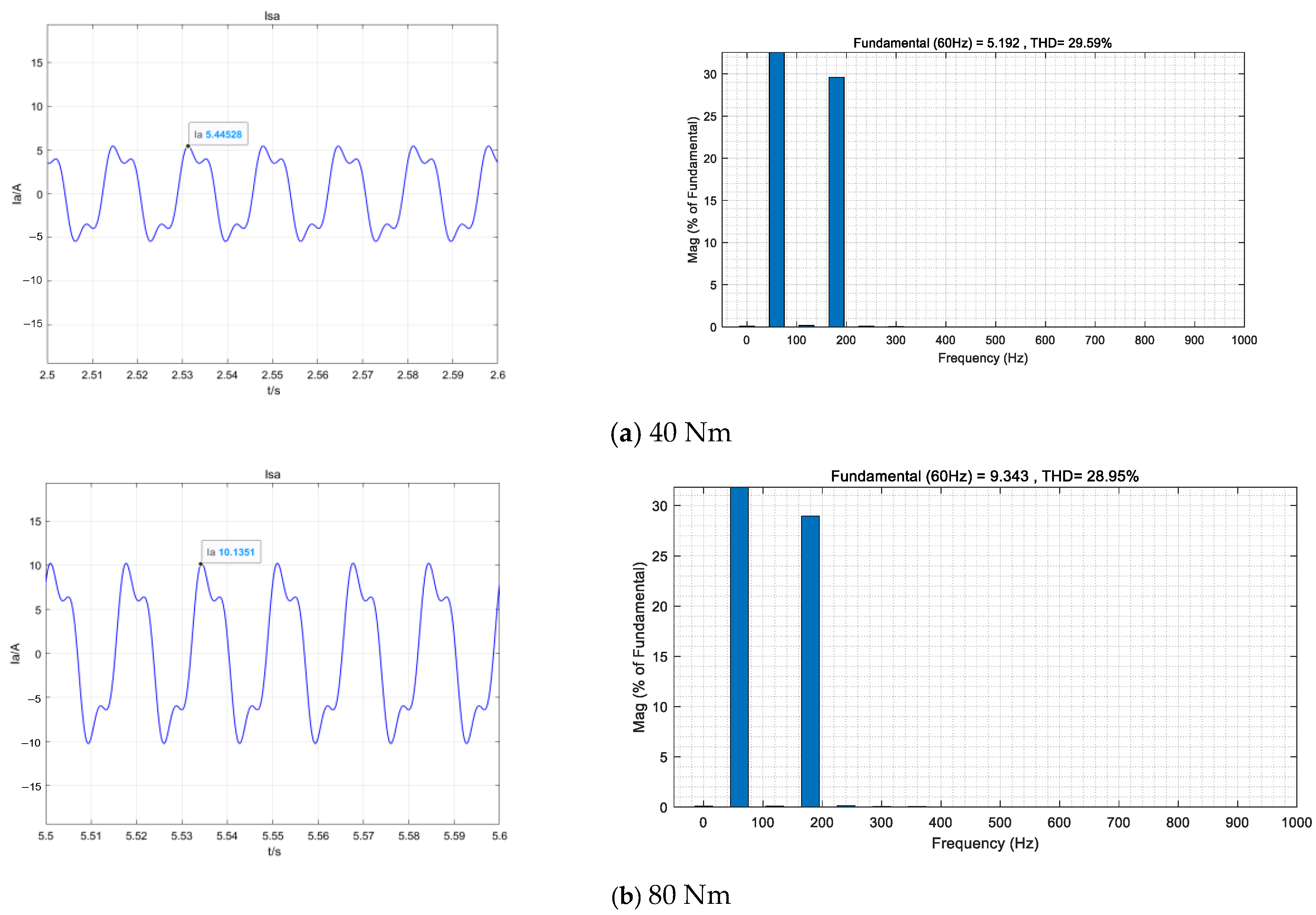
Figure 15 shows the MTPA phase current waveform of the virtual signal injection method under the two-space control structure. The above equations show that the MTPA effect of the fundamental space is no different from that of the single space. Here, it is verified that the effectiveness of the virtual signal injection MTPA control method in the fundamental plane is still valid under the single space and double space control structures.
In
Figure 16, the third harmonic current
Iq3 is injected on the basis of the above, and its amplitude is calculated by Equation (33). The stable torque is generated by the interaction between the third harmonic current and the third harmonic component in the permanent magnet flux chain. Because the third harmonic contributes extra torque, the fundamental current amplitude decreases by 7.3% under the same load, and the effective current value including the third harmonic decreases by 2.7%.
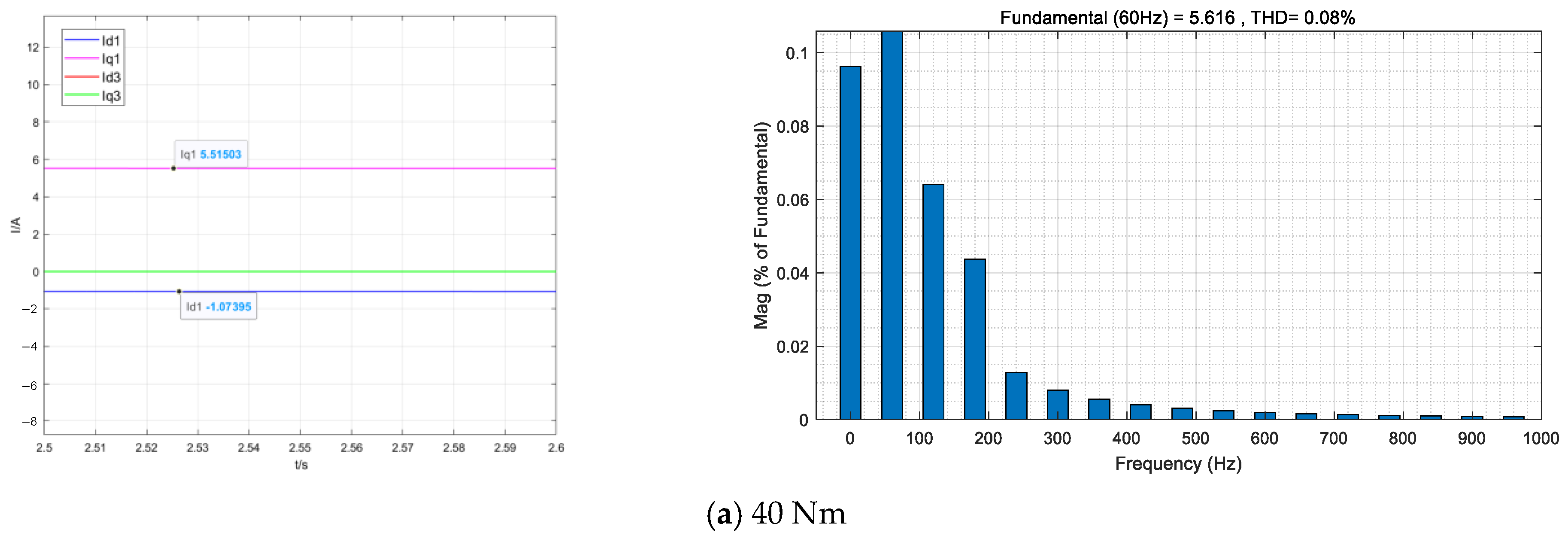
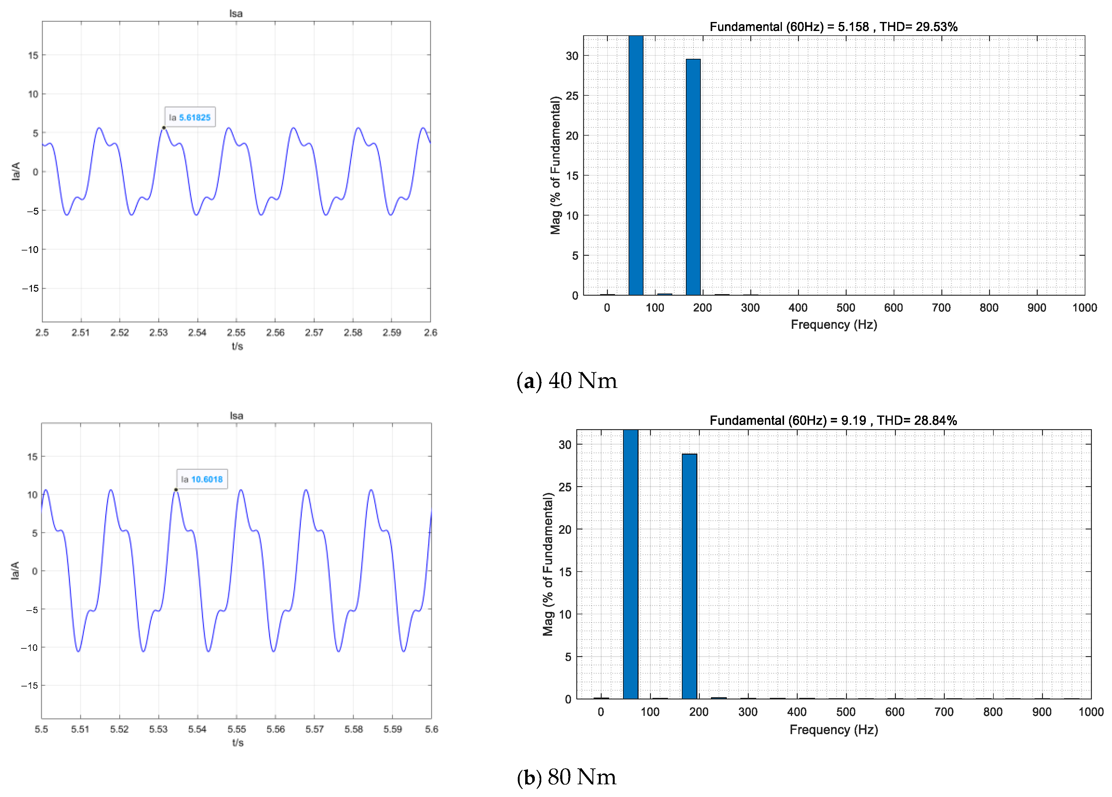
On the basis of the above, the injected third harmonic current is injected into the direct axis and the cross-axis components of the MTPA distribution current by virtual signal, and the effect is shown in
Figure 16. Because the harmonic current MTPA contributes extra torque, the fundamental current amplitude decreases by 1.8%, and the total current RMS decreases by 1.6% compared to
Iq3 only.
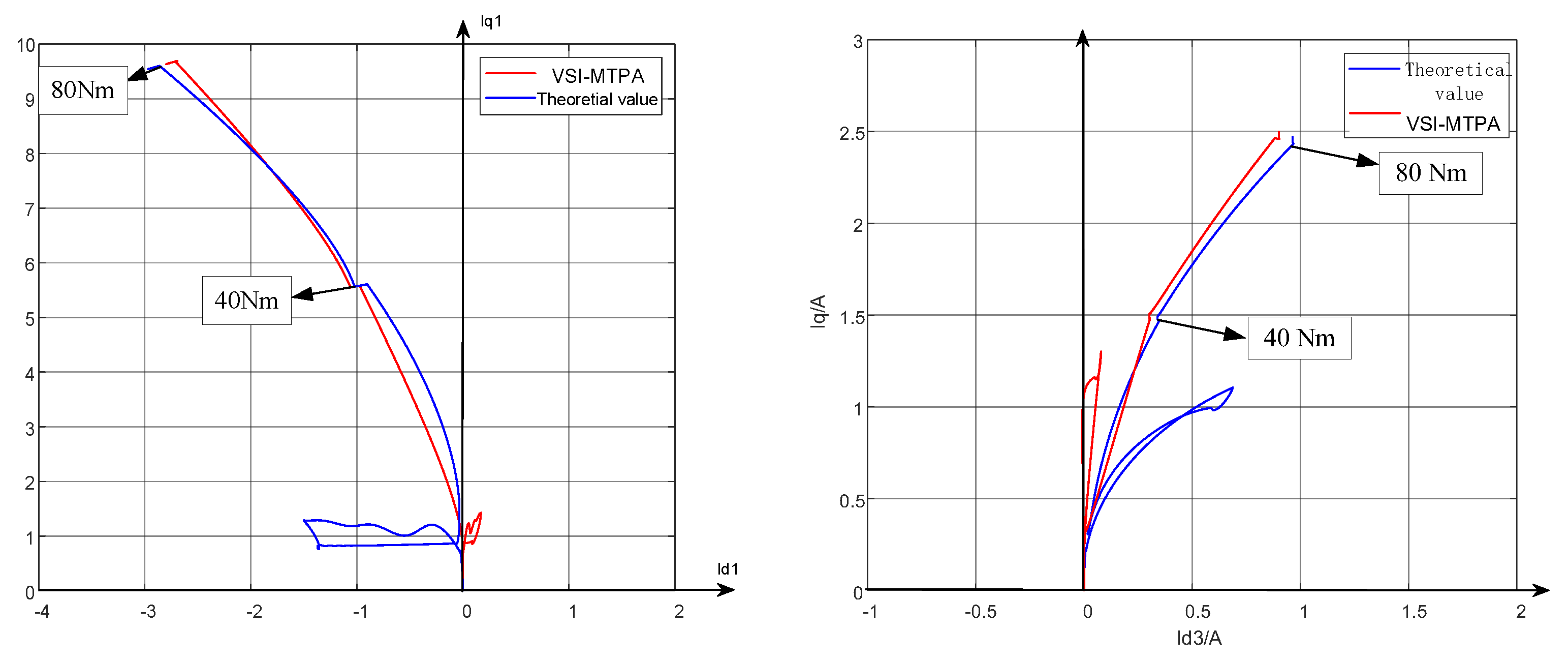
Figure 17 shows the current trajectory of the third harmonic space formula method and the virtual signal injection method MTPA under the two groups of loads. The current error of the virtual signal injection method is about 7%.
Figure 15 shows the changes in the effective current values corresponding to the two groups of loads under each control mode. Among them: (1) single space MTPA is introduced and the fundamental reluctance torque of the five-phase motor is used; (2) double space vector control structure is used to suppress the negative torque caused by uncontrolled third harmonics; (3) the controlled third harmonic current is injected to interact with the third harmonic component of the permanent magnet magnetomotive force to produce stable torque; (4) MTPA is applied to the injected third harmonic current to distribute the direct axis and alternating axis current, using the third harmonic torque. The introduction of each step can improve the torque obtained at the same current, which proves that the proposed multi-dimensional MTPA control strategy can improve the torque output capacity below base speed on the object five-phase permanent magnet motor.
5. Conclusions
To fully exploit the reluctance torque of a five-phase interior permanent magnet synchronous motor (IPMSM) for enhanced torque output performance, the Maximum Torque Per Ampere (MTPA) control methodology commonly applied to three-phase PMSMs can be adopted. However, the increased control dimensionality inherent to five-phase motors renders conventional MTPA strategies inadequate for harnessing harmonic plane torque. This chapter proposes a virtual signal injection-based multidimensional MTPA control strategy for five-phase IPMSMs with third harmonic back-EMF, targeting torque performance optimization across the full sub-rated speed range. Key contributions and findings include the following:
(1) Mathematical modeling of the five-phase IPMSM with third harmonic back-EMF, deriving a synchronous rotating reference frame model encompassing fundamental and harmonic planes, and establishing a dual-plane vector control structure based on stator field orientation.
(2) Comparative analysis demonstrating superior torque output under dual-plane MTPA control versus fundamental-plane-only MTPA control, with theoretical verification confirming that dual-plane optimization enhances torque density for motors with harmonic back-EMF.
(3) Development of a multidimensional MTPA strategy employing distinct virtual signal injections for fundamental and harmonic planes, including computational methods for virtual signal synthesis to avoid inter-plane interference, along with detailed MTPA factor extraction and operating point tracking procedures.
(4) Simulation and experimental validation showing that the proposed strategy improves torque output under identical inverter capacity constraints, with enhancement magnitude proportional to the harmonic-to-fundamental back-EMF ratio. The method achieves accurate tracking of dual-plane MTPA operating points with errors below 5% and demonstrates robust dynamic performance.
Author Contributions
Conceptualization, Y.Q.; Writing—original draft, Y.Q.; Writing—review & editing, Y.Q., P.Z. and Z.Y.; Supervision, Writing—review & editing, H.X. All authors have read and agreed to the published version of the manuscript.
Funding
This research was funded by Key R&D Program of Shandong Province, China (Major Science and Technology Innovation Project) grant number (2021CXGC010208) and The APC was funded by Key R&D Program of Shandong Province, China (Major Science and Technology Innovation Project).
Data Availability Statement
The original contributions presented in this study are included in the article. Further inquiries can be directed to the corresponding author.
Conflicts of Interest
The authors declare no conflict of interest.
References
- Qin, Y.; Zhou, P.; Xu, H. Virtual-Signal-Injection-Based Dual-Plane MTPA Control for Five-Phase PMSM. In Proceedings of the 12th IEEE Global Conference on Reliability and Prognostics and Health Management (PHM-Nanjing 2021), Nanjing, China, 15–17 October 2021. [Google Scholar] [CrossRef]
- Tang, Q.; Shen, A.; Luo, P.; Shen, H.; Li, W.; He, X. IPMSMs Sensorless MTPA Control Based on Virtual q-Axis Inductance by Using Virtual High-Frequency Signal Injection. IEEE Trans. Ind. Electron. 2020, 67, 136–146. [Google Scholar] [CrossRef]
- Liu, G.; Song, C.; Chen, Q. FCS-MPC-Based Fault-Tolerant Control of Five-Phase IPMSM for MTPA Operation. IEEE Trans. Power Electron. 2020, 35, 2882–2894. [Google Scholar] [CrossRef]
- Sun, T.; Wang, J.; Koc, M. On Accuracy of Virtual Signal Injection based MTPA Operation of Interior Permanent Magnet Synchronous Machine Drives. IEEE Trans. Power Electron. 2017, 32, 7405–7408. [Google Scholar] [CrossRef]
- Liu, G.; Wang, J.; Zhao, W.; Chen, Q. A Novel MTPA Control Strategy for IPMSM Drives by Space Vector Signal Injection. IEEE Trans. Ind. Electron. 2017, 64, 9243–9252. [Google Scholar] [CrossRef]
- Sun, T.; Wang, J.; Chen, X. Maximum Torque Per Ampere (MTPA) Control for Interior Permanent Magnet Synchronous Machine Drives Based on Virtual Signal Injection. IEEE Trans. Power Electron. 2015, 30, 5036–5045. [Google Scholar] [CrossRef]
- Antonello, R.; Carraro, M.; Zigliotto, M. Towards the Automatic Tuning of MTPA Algorithms for IPM Motor Drives. In Proceedings of the XXth International Conference on Electrical Machines (ICEM), Marseille, France, 2–5 September 2012; pp. 1121–1127. [Google Scholar] [CrossRef]
- Lee, K.; Lee, S.B. MTPA operating point tracking control scheme for vector controlled PMSM drives. In Proceedings of the SPEEDAM 2010, Pisa, Italy, 14–16 June 2010; pp. 24–28. [Google Scholar] [CrossRef]
- Zhang, L.; Wang, X.; Zhu, X.; Chen, X.; Chen, C. Extended Multioperating Mode Control Strategy for Five-Phase Flux-Intensifying Interior Permanent Magnet Motor Based on VSI-MTPA and FW Control. IEEE Trans. Transp. Electrif. 2025, 11, 1518–1528. [Google Scholar] [CrossRef]
- Zhang, L.; Dong, C.; Zhu, X.; Chen, X.; Pei, Z. A Fault-Tolerant MTPA Control Strategy of Five-Phase Flux-Intensifying Fault-Tolerant Permanent-Magnet Motor with Sliding-Mode Disturbance Observer Under Open-Circuit and Short-Circuit Faults. IEEE Trans. Ind. Electron. 2024, 71, 13650–13658. [Google Scholar] [CrossRef]
- Pang, J.; Liu, W.; Jiao, N. MTPA Control of Wound-Rotor Synchronous Start/Generator Drives Based on Virtual Signal Injection Considering Cross-Coupling Effect in Low-Speed Range. IEEE Trans. Power Electron. 2024, 39, 6115–6124. [Google Scholar] [CrossRef]
- Liu, G.; Chen, Z.; Xu, L.; Jiang, T.; Chang, L. MTPA Control for DC-Biased Hybrid Excitation Machine Using MTPA Control Law and Virtual Signal Injection. IEEE Trans. Transp. Electrif. 2024, 10, 1571–1582. [Google Scholar] [CrossRef]
- Chen, Q.; Zhao, W.; Liu, G.; Lin, Z. Extension of Virtual-Signal-Injection-Based MTPA Control for Five-Phase IPMSM Into Fault-Tolerant Operation. IEEE Trans. Ind. Electron. 2019, 66, 944–955. [Google Scholar] [CrossRef]
- Yang, Y. Direct Torque Control of Five-Phase Interior Permanent Magnet Synchronous Motor Based on Signal-Injection MTPA. Master’s Thesis, Jiangsu University, Zhenjiang, China, 2019. [Google Scholar]
- Li, F.; Xia, C. Inductance Identification Algorithm for IPMSM Considering Magnetic Circuit Saturation and Variable-Parameter MTPA Control Strategy. Trans. China Electrotech. Soc. 2017, 32, 136–144. [Google Scholar] [CrossRef]
- Kim, S.; Yoon, Y.; Sul, S.; Ide, K. Maximum Torque per Ampere (MTPA) Control of an IPM Machine Based on Signal Injection Considering Inductance Saturation. IEEE Trans. Power Electron. 2013, 28, 488–497. [Google Scholar] [CrossRef]
- Lu, L.; Semail, E.; Kobylanski, L.; Kestelyn, X. Flux-Weakening Strategies for a Five-Phase PM Synchronous Machine. In Proceedings of the 2011—14th European Conference on Power Electronics and Applications, Birmingham, UK, 30 August–1 September 2011; IEEE: New York, NY, USA, 2011. [Google Scholar]
- Onsal, M.; Demir, Y.; Aydin, M. A New Nine-Phase Permanent Magnet Synchronous Motor With Consequent Pole Rotor for High-Power Traction Applications. IEEE Trans. Magn. 2017, 53, 11. [Google Scholar] [CrossRef]
- Shayeghan, M.; Di Benedetto, M.; Lidozzi, A.; Solero, L. HIL-Based Fault-Tolerant Vector Space Decomposition Control for a Six-Phase PMSM Fed by a Five-Level CHB Converter. Energies 2025, 18, 507. [Google Scholar] [CrossRef]
- Khadar, S.; Kaddouri, A.M.; Kouzou, A.; Hafaifa, A.; Kennel, R.; Abdelrahem, M. Experimental Validation of Different Control Techniques Applied to a Five-Phase Open-End Winding Induction Motor. Energies 2023, 16, 5288. [Google Scholar] [CrossRef]
| Disclaimer/Publisher’s Note: The statements, opinions and data contained in all publications are solely those of the individual author(s) and contributor(s) and not of MDPI and/or the editor(s). MDPI and/or the editor(s) disclaim responsibility for any injury to people or property resulting from any ideas, methods, instructions or products referred to in the content. |
© 2025 by the authors. Licensee MDPI, Basel, Switzerland. This article is an open access article distributed under the terms and conditions of the Creative Commons Attribution (CC BY) license (https://creativecommons.org/licenses/by/4.0/).


