Article

Improving Efficiency of Rolling Mill Stand Electric Drives Through Load Alignment

by
Stanislav S. Voronin
1,
Andrey A. Radionov
1,
Alexander S. Karandaev
1,
Roman A. Lisovsky
1,
Boris M. Loginov
1,
Mark A. Zinchenko
2,
Vadim R. Khramshin
2 and
Ivan N. Erdakov
3,*
1
Department of Automation and Control, Moscow Polytechnic University, 107023 Moscow, Russia
2
Power Engineering and Automated Systems Institute, Nosov Magnitogorsk State Technical University, 455000 Magnitogorsk, Russia
3
Department of Metal Forming, South Ural State University, 454080 Chelyabinsk, Russia
*
Author to whom correspondence should be addressed.
Energies 2025, 18(12), 3175; https://doi.org/10.3390/en18123175
Submission received: 15 April 2025 / Revised: 1 June 2025 / Accepted: 10 June 2025 / Published: 17 June 2025

Abstract

:
The problem of reducing electric power consumption is critical to ferrous metallurgy as it is a very energy-intensive industry. Significant energy savings can be achieved by increasing the efficiency of high-power electric drives of rolling mills. Experiments with the 5000 plate mill showed that the deterioration of energy efficiency can be caused by the misalignment of loads between the upper and lower roller main electric drive motors (upper main drive/UMD and lower main drive/LMD, respectively) caused by the misalignment of roller motor speeds. Experiments showed that when the speed misalignment reaches 5%, the motor torques differ by two times. Various UMD and LMD speeds can be set to bend the front end of the workpiece (form a “ski”). The installed load division controller (LDC) option fails to provide load alignment due to a low response rate and late startup. This article’s contribution consists of the development of a forced UMD and LMD speed and torque alignment method. To implement this method, a load-division controller with a switching structure has been developed. The authors also developed an efficiency and electric loss monitor and provided an experimental assessment of electric losses per one-pass and per sheet batch rolling cycle. The prospects of this research include the optimization of high-speed and high-load electric drive modes to reduce the energy costs of rolling and the development of an LDC based on fuzzy logic algorithms.

1. Introduction

Ferrous metallurgy is one of the most energy-intensive industries. Steel production is a major factor in energy consumption, electricity losses, and environmental pollution [1]. Power consumption makes 15–20% of all operational costs of a metal plant and is directly linked to the greenhouse gas regulations fulfillment [2]. Therefore, promoting energy-efficiency improvements is a key initiative stimulating energy saving, emission reduction, and carbon neutrality [3]. Reducing the energy costs of metal sheet production is a relevant problem. This is caused by the high energy intensity of rolling. Hot rolling takes up about 8% of the total metal plant power consumption. The consumption of electricity is up to 20% of the total energy costs. The specific electricity consumption is 80 kW per ton of hot-rolled products on average [4]. This means that this industry can achieve significant energy savings through the reduction of electric power consumption.
The problem of reducing electricity losses in electric drives has been addressed by multiple researchers. For instance, the authors of [5] reviewed the problems of improving energy efficiency by using new high-quality active materials in electrical machines and optimizing their power circuits. The authors of [6] presented developments that help reduce losses in electric drives of broad-strip hot mills. The authors of [7] improved the energy efficiency of electric drives in reverse rolling stands by improving control methods and systems. It is important to reduce the energy consumption in plat mill stand electric drives, which are the most energy-intensive components. This is because they are fitted with “megawatt electric drives with rotation frequency control that operate at low angular speeds” [8]. Additionally, rolling is performed with heavy drafting. The horizontal stands of the modern 5000 plate mill considered in this paper are equipped with two synchronous 12 MW motors (Figure 1). The motor brand is VEM DMMYZ 3867-20V, and their rated parameters are provided in Table 1.
The power circuit of the frequency converter (FC) MV7308 SA AFE installed in electric drives was studied in [9]. The rated parameters are provided in Table 2. The three converters operating in parallel and synchronously are powered separately via step-down transformers.
The electricity loss value can be determined using the efficiency factor. The equivalent efficiency of electric drives is influenced by the efficiency of all power circuit components, especially the motors and the FCs. The efficiency of any electromechanical system depends on loading. For AC electric motors under full loads, it ranges from 80% for low-power motors and 95% for motors with power ratings over 100 kW [10]. For practical reasons, engineers strive to achieve maximum efficiency when the shaft load is 75% of the rated one while designing electrical machines. However, the efficiency of electric motors drops significantly when the load is below 40%. Apart from that, the efficiency of the electric drive can be reduced when loads are above the rated level [11,12]. This is confirmed by the efficiency/torque graph in Section 4.2 for the motor in question.
The actual loads of the horizontal stand electric drives in the 5000 mill range between 0.5TN and 2.4TN, which is confirmed by the oscillograms shown in Figure 2. They were obtained over seven finishing rolling passes. The torque MU of the upper roller motor is three times higher than the torque ML of the lower roller motor and reaches the limit set at 4200 kN m. Thus, it is 2.2 times higher than the rated torque (1910 kN m) provided in Table 1. The average torque ML of the lower roller motors in the first four passes is below the rated value. In the first two passes, the average values of UMD and LMD motors differ by over four times. This example allows us to draw the conclusion that the efficiency of these electric drives is far from maximum, which results in increased electricity losses.
The authors of [13] provide the oscillograms of speeds, torques, and currents for the upper and lower roller motors for six roughing rolling passes for a batch of six workpieces. They also provide oscillograms obtained after 19 finishing rolling passes for one of the workpieces from the batch. The data confirm that in each roughing pass, the average LMD motor current was almost three times greater than the UMD motor load. In finishing passes, the ratio of loads was the opposite: the torques and currents of the upper roller motors exceed the same parameters of the lower roller motor by two times or more. Only in the final finish rolling passes are the loads approximately equal.
The motor torques are affected by changes in drafting across passes and uneven UMD and LMD loads. The first parameter is determined by process programs and cannot be adjusted during rolling. The second parameter depends on the ratio of speeds (and, subsequently, torques) of the UMD and LMD. These ratios are set before passes and can be adjusted by the operator. They are required to bend the front end of the workpiece (form a “ski”), which will be considered in Section 3.1. The uneven loading of electric drives results in the overheating of the motor with a greater load, increased insulation wear, and excess accident risk [14,15]. When the loads of variable-frequency drives (VFDs) are low, the efficiency decreases as well, which causes greater electricity losses [16].
Thus, the uneven distribution of roller motor loads is a key cause of efficiency reduction and electricity losses. It is necessary to consider this fact when working with high-power synchronous electric drives of plate mills. However, this problem has been understudied as confirmed by the review of publications below.

2. Review of Publications

The problems of loss change depending on the rolling mill electric drive load were reviewed in [17,18]. The authors of [19] claim that “the uneven distribution of loads in multi-motor electric drives cause overloads that result in the overheating of motor windings”. This deteriorates the insulation properties and can even cause burning out, as well as power losses due to the low operation efficiency under load [20]. Normally, a dual-circuit speed control system is designed for upper and lower roller electric drives to control the speed and torque of each motor separately [21,22]. The authors of [23] established that the synchronous operation of two motors in a single-stand rolling mill has a direct impact on the production line efficiency. The authors of [24] state that “a science-based rolling schedule is the main guarantee of the rolling mill production power, product quality, energy-saving, and reduced power consumption”. Thus, analyzing the causes of rolling stand electric drive load inequality and developing technological solutions to eliminate them are relevant research problems. In this paper, they are addressed using the electric drives of the 5000 mill horizontal stand. We also conduct a preliminary analysis of the load impact on the efficiency of frequency-controlled drives.

2.1. Efficiency of Frequency-Controlled Drives Under Variable Loads

In variable-frequency drives, the motor efficiency can be calculated using load, frequency, and voltage. We studied the impact of output FC voltage on the efficiency of the electric drive [25]. It is confirmed that this parameter is not only affected by the motor load but also by the output converter frequency. The authors of [26] also conclude that the motor efficiency changes depending on its speed and load. “Although there are multiple methods measuring the efficiency of motors at a partial load and full speed, few of them are suitable for efficiency assessment at partial speed”. The rated efficiency of the motor is commonly stated in its datasheet. This parameter is only accurate for the rated load and speed. It is stressed that “the variable loads and speeds due to the usage of VFDs make motor efficiency assessment a challenging and important issue”. However, according to the publications review, “there are no well-tested engineering motor efficiency assessment methods that provide for a sufficiently high accuracy and reliability for the given conditions”.
We know that motor efficiency is determined as a ratio of output power P1 and input power P2 following the dependency [26]:
η = P 1 P 2 .
It can also be expressed using power losses ΔPLoss
η = 1 Δ   P L o s s .
These expressions show that there are technically two approaches to calculating motor efficiency. The simplest direct calculation method is based on the measurement of its input and output powers. The input power can be easily determined using a power probe or multimeter but the output power is hard to measure due to the non-sine signal form. It can be evaluated indirectly by changing the motor speed and the shaft torque, which, in engineering terms, is more applicable in laboratory conditions than in the field [27]. The main problem of this approach is the complexity of metering the torque on the mechanical drive shaft during rolling. However, this problem can be solved relatively easily by an elastic torque observer on the rolling stand spindle. The observer is a part of a program developed and deployed in the industrial logic controller software and therefore it does not require installation and maintenance. The device and the observer deployment results for the 5000 mill are considered in [28]. Its utilization prevents problems associated with the calculation of power losses and efficiency in the online mode.
Since efficiency is inversely proportional to losses in the motor, it can alternatively be calculated based on power losses. Losses in the motor can be classified as constant and variable. Constant losses include losses in magnetic core, friction losses, and cooling (ventilation) losses. Variable losses include losses in the stator and rotor and various parasitic losses. Their values are closely related to the structure of the motor, its material, and physical parameters like power, resistance, impedance, and inductance. With this approach, power losses can be analyzed using equivalent circuits [29]. However, it is not always convenient to obtain the physical parameters of a motor in operation, especially when it is a high-power electric drive of a rolling mill. In addition, when the motor operates under partial loads at a speed below rated, the results of physical measurements may be inaccurate. At variable speeds, the efficiency of the motor differs from the value calculated for the rated speed. Nevertheless, very few research papers contain information on motor efficiency at variable speeds, although there are efficiency/load graphs at a constant (as a rule, rated) speed.
Thus, the aforementioned methods of efficiency calculation have practical restrictions due to the lack of necessary motor parameters and complex measurements. The methods are suitable for calculations during full-speed operation. But they cannot be used with VFDs when the load values change in a wide range, which is typical of rolling mills. Simultaneously, there are few publications discussing the impact of speed on motor efficiency [26].
The authors of [30] use the term “weighted average efficiency” for the general case when speed control is done at variable loads. They suggest a calculation procedure based on the following formula:
η = P 2 / P 2 + Δ   P L o s s ,
where P2 is the motor shaft power.
When the motor operates at various angular speeds, we suggest calculating the weighted average efficiency ηp per a control cycle that consists of m stages:
η p = 1 m P 2 q t q / 1 m P 2 q + Δ   P q t q ,
where P2q and ΔPq are the useful power and losses at stage q; tq is the time during which the motor operates at stage q.
However, this approach cannot be used for a rolling mill electric drive as the rolling process is not continuous and has pauses. This is confirmed by the speed and torque oscillograms shown in Figure 2, and the oscillograms provided in [13]. Excluding pauses from the calculations is complicated because it essentially requires tracking the motor load and calculating average values for each pass. Additionally, the averaging of torques for each pass is a labor-intensive problem virtually impossible to solve due to a wide range of rolled products.

2.2. Efficiency Calculation Methods

The authors of [31] claim that “the motor efficiency can be assessed precisely through standard laboratory tests”. While assessing the efficiency of the motor in the operating mode, it is preferable to use the methods of equivalent circuit and air gap torque (AGT). The drawbacks of the first method were discussed above, and the AGT method [32] requires oscillograms of voltage and current, as well as stator resistance, which may require stopping the motor to collect data. As a result, multiple research papers suggest equivalent circuit parameter assessment procedures using the methods of artificial intelligence. For instance, the authors of [33] suggest identifying asynchronous motor parameters based on a genetic algorithm. However, this method was only tested in one mode, which prevented its verification. The authors of [31] suggested analyzing the efficiency of motors using an equivalent circuit based on particle accumulation optimization. This approach aimed to assess the efficiency of motors without shutdown based on non-intrusive measurements. The measured motor parameters include current, power, voltage, and speed, which do not require using additional equipment.
Genetic algorithms and methods based on a particle swarm proved effective for asynchronous electric drives with a smoothly changing (fan) load. There is no information on the successful usage of these methods for electric drives of rolling mills. These methods will probably not be effective due to the following:
  • Efficiency calculation accuracy is very sensitive to changes in equivalent circuit parameters. These parameters depend on load but the dependency is non-linear.
  • The load torque of the stand electric drive is measured discretely (pass by pass) or continuously during each pass. In this case, the optimization of the equivalent circuit is very complicated.
The mentioned methods are complex and require a large number of parameters and high measurement accuracy for further calculations. As mentioned above, they were only tested in laboratory conditions. The operating conditions require a method that can be easily implemented on site. Thus, it is feasible to calculate (recover) electricity losses and the efficiency of rolling mills using the parameters measured in the online mode or obtained from data arrays formed during rolling. This requires the development of a calculator (observer) for energy parameters like power consumption and efficiency. The observer operation can be demonstrated using the pre-recorded signals imported to MATLAB from the IbaPDA (Process Data Acquisition System) installed on the rolling mill [34]. This stationary system is installed on the mill and is currently in operation. The accuracy and reproducibility of the results is checked regularly by the operators and is therefore unquestioned. No special sensors were installed, and no data processing methods were used.

2.3. Existing Rolling Mill Electric Drive Speed and Load Alignment Systems

The alignment of loads between the electric drives of a rolling stand can be seen as a specific case of Multi-Motor Synchronous Control Methods reviewed in [35]. This publication reviews the advantages and disadvantages of three representative control algorithms including the proportional-integral-differential (PID) control, model forecasting control, and sliding mode control. The authors of [36] consider fuzzy algorithms used to control multiple-motor systems designed for high-power high-inertia electric drives [37]. They also study the control methods for such systems focusing on fuzzy logic with different control goals. The authors of [38,39] also discuss fuzzy algorithms in multiple-motor systems. In rolling mills, similar problems have to be solved while adjusting the power link (generally, tensioning) in the subsequent stands and while adjusting the loads of the electric drives of the upper and lower rollers in a stand. This paper presents a solution to the latter problem.
The authors of [40] studied a relatively simple method of controlling load balance between the upper and lower rollers in the quarto stand of a hot rolling mill. They suggest using the difference in torques to adjust the upper roller motor current. Based on the modeling results, the authors conclude that “the suggested method can effectively control and maintain the balance of loading”. To solve the problem of load imbalance between the electric drives of rolling stands, the authors of [23] use the cross-link method. It facilitates synchronous roller motor control. They developed a fuzzy PID controller to balance loads when they are misaligned due to an external factor or control algorithm errors. Moreover, to improve the alignment of motor speeds, a PI tracking controller was developed. To solve a similar problem, the authors of [41] developed a new type of load-balancing controller using the load observer. They suggest a control method for the production parameters of a single-neuron adaptable PID controller. Based on the modeling result, we can assume that this method can facilitate load balancing for roller motors with high control precision.
Similar problems were solved in [35,42,43]. For instance, the authors of [42] employed a cross-link structure using the speeds of two motors as the input signals of the controller. Speed misalignment compensation allowed attaining synchronous control between the motors. The authors of [35] suggest a master/slave synchronous control structure. In this case, the armature current was used as the input parameter of the controller to synchronize the speeds and torques of the vertical roller motors. The authors of [43] used the synchronous cross-control structure and the PI controller to build a synchronous control system that maintains the load balance between the upper and lower roller motors.
The review of publications showed that the existing R&D share some common drawbacks:
-
they are difficult to implement on an operating rolling mill at variable loads;
-
there are no experimental research and industrial trials.
All the developed electric drive control algorithms were only studied using mathematical modeling methods. Despite the fact these R&D were made a relatively long time ago, papers show no data on their industrial deployment.
This confirms the relevance of developing a technical solution for load alignment between the upper and lower roller motors with a sufficient accuracy and response rate. However, we do not attempt to compensate for torque deviations during rolling. In plate mills, this problem is successfully solved by an automatic roller gap and thickness control systems based on the ROLL-GAP CONTROLL concept [44,45,46]. This concept was developed by SMS Demag AG and used in the 5000 mills [47].

3. Problem Statement

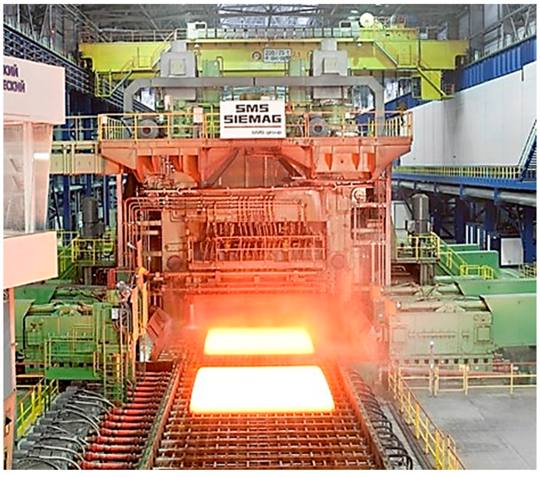
3.1. Control Object Description

Plate rolling mill stands are designed for reverse rolling of workpieces following the set rolling programs. In the series 5000 modern rolling mills, operating in several countries, slabs are rolled in a horizontal quarto stand fitted with two working and two support rollers and a drafting stand with two vertical rollers. A photograph of the horizontal stand of the 5000 mill taken from the side of the runout table is shown in Figure 3. It explains the rolling of a batch of several workpieces (a single batch may include up to six workpieces). During the initial (roughing) stage, they are rolled in turns with intermediate cooling on a roller table following the controlled thermomechanical rolling technology [48,49]. During the finishing stage, each sheet is rolled in several passes until the set thickness is achieved. The roughing stage normally consists of 7–9 passes, and finishing up to 19 passes.
When the workpiece leaves rollers, it is transferred on a run-out or run-in roller table depending on the rolling direction (pass number). The workpiece can move freely if its front end has the correct shape. If the workpiece is bent down, it can hit the rollers, which shall result in their premature wear. This drawback can be eliminated by shaping a ski-shaped upward bend in the front end of the workpiece (Figure 4a) [50]. This method is employed by most plate and broad-strip hot-rolling mills.
This technology is referred to as asymmetric rolling; it was studied in a large number of publications including [51,52,53]. The front end 6 bend directions at the stand output are shown in Figure 4b. The upward bend 4 is formed by setting the speed V2 of the lower roller 2 higher than the speed V1 of the upper roller 1. The opposite direction 5 bend is unacceptable as it increases the probability of the workpiece sticking as it leaves the stand or travels along the roller table. Electric drive control systems adjust roller speeds separately. These include ski-formation and load alignment systems. The first system controls the ratio of speeds required to achieve the set bend radius and length. The second one includes an LDC that aligns the speeds and torques of motors in the quasi-steady rolling mode. These systems operate at different times: the LDC operates following a set pause after the ski formation.
In the diagram, shown in Figure 5, the inputs of UMD and LMD speed controllers are connected to the speed setup unit. Apart from speed chart formation, it has to provide the workpiece bending. The lower roller electric drive speed is the basic parameter that depends only on the set rolling speed. The module adjusts the UMD speed setting according to the calculated speed difference reduction rate after gripping. The maximum misalignment setting (the ski size) is 10%, and it is set before the pass. When the workpiece enters the stand, the speed difference reduces to zero. After that, the LDC is activated to align the motor torques while rolling the main part of the workpiece.
The considered draft ski formation algorithm has some drawbacks that reduce its efficiency. The main problem is that irrespective of the initially set speed difference, the workpiece bends uncontrollably due to a number of process factors [54,55]. They include the temperature gradient across the workpiece thickness, uneven roller wear, etc. They cannot be measured or controlled. Apart from the reduced stability of rolling and increased risk of the workpiece sticking as it leaves the stand, the difference in UMD and LMD speeds results in increased electricity losses. As shown above, this can be caused by the reduced efficiency both at under- and overloads. Thus, rolling with different motor loads when one of them is overloaded and the other’s torque is below the rated value is inefficient in terms of power consumption.

3.2. Analysis of Oscillograms with Draft Settings of the Ski Formation System and the LDC

Figure 6 shows the speed and torque oscillograms for the upper and lower roller motors representing the load distribution at rolling over the interval t1t7. Right after the workpiece enters the stand at torque t1, the torque of the LMD motor is limited to 4200 kN m. Over the interval t2t3, it is more than two times greater than the torque of UMD, which ranges between 800 and 1900 kN m. The formation of the ski takes place over the interval t2t4, while the signal ΔV Speed Difference for the Ski (panel 5) is reduced at a set rate. Then at the torque t5, signal uLDC occurs on the LDC output (panel 1), which results in the forced alignment of the motor speeds VU, VL (panel 4) and torques MU, ML (panel 3). However, due to the rate of torque alignment, their difference ΔMU-L (panel 2) drops to zero only by the torque t6. As a result, rolling over the interval t1t6 is performed at non-identical torques MU and ML (panel 3). This confirms that the current settings of the load alignment system cannot provide the equal loading of UMD and LMD motors. In the following sections, we shall show that the LDC has no time to operate with short workpieces during the roughing stage.
The analysis of the oscillograms provided shows that:
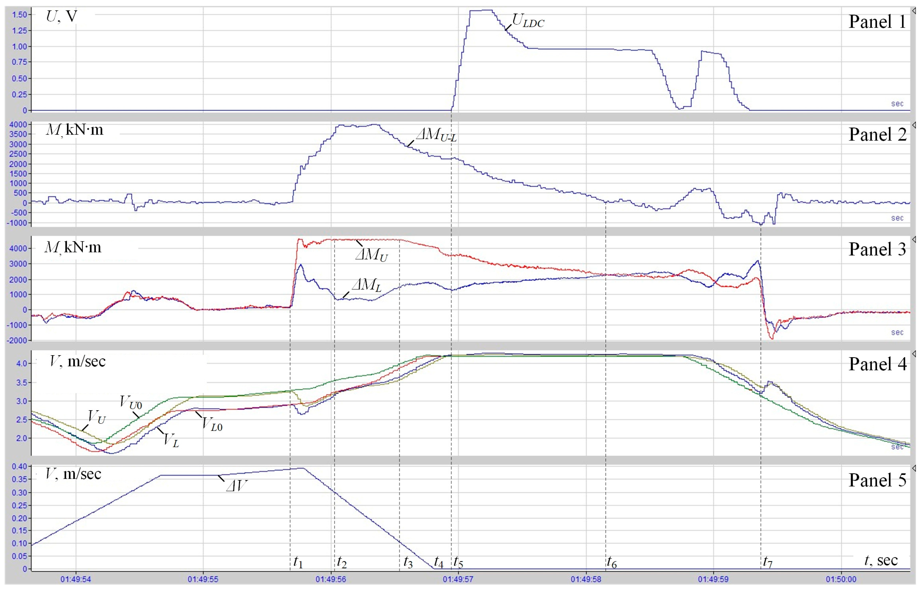
  • During the ski-formation system operation, the LDC operation is blocked. The speed adjustment signal at the LDC output (panel 1) occurs only after the Speed Difference for the Ski signal is removed (panel 5). Moreover, it is generated with a delay (t4–t5) and almost immediately reaches the limit.
  • During the operation of the ski-formation system, the LMD torque (panel 3) reaches the limit, while the UMD load is approximately twice below the rated value.
  • After the signal occurrence on the LDC output (panel 1), loads are slowly aligned (panel 3).
The experiments conducted confirmed that the unacceptable differences in electric drive loads are caused by the low response rate of the LDC and the ski-forming system. This results in the uneven distribution of load between the UMD and LMD motors in the steady rolling mode, which causes increased electricity losses due to reduced efficiency. These considerations confirm the relevance of improving the electric drive control method that would allow for a faster response rate of the UMD and LMD load alignment system (over the interval t5t6 in Figure 6). We do not aim to increase the response rate in the ski formation mode (the interval t1t4) in this research. This problem can be solved by the stand electric drive control method for the asymmetric rolling mode of the workpiece front end developed in [56]. It facilitates the reduction of the set speed misalignments in the ski-formation mode but does not affect the LDC operation.

3.3. Research Objectives

Based on the above, we formulated the purpose of this research: reducing the electricity losses in plate rolling mill stand electric drives by increasing the equivalent efficiency of motors through the reduction of roller motor speed and torque alignment time in the quasi-steady rolling mode.
To that end, we set the following objectives:
  • Analyzing the electricity losses with the draft UMD and LMD control algorithm. Justifying the torque alignment method based on motor speed alignment. Developing the LDC with a switching structure to facilitate the method implementation.
  • Developing an observer for electricity losses recovered using electric drive parameters. Using the observer to assess the losses in the draft and developed electric drive control algorithms.
  • Conducing an experimental analysis of loss reduction following the deployment of the algorithm accelerating speed alignment.

4. Materials and Methods

Below, we use oscillogram analysis to confirm the impact of UMD and LMD motor speed misalignment on the ratio of torques to evaluate the relevance of improving the electric drive control method. To this end, we conducted an experiment when the ratio of electric drive speeds during the subsequent rolling of workpieces in the same pass changed without operators’ inputs.

4.1. Speed Alignment Experiment with Existing Control Algorithms

Figure 7a shows the oscillograms of torques (panel 1) and linear speeds (panel 2) of UMD and LMD motors during the rolling with the set speed misalignment ΔV = 5%. This should provide the upward bend on the front end, although this does not happen due to the great thickness of the workpiece. These were obtained during the first roughing pass. Figure 7b shows similar oscillograms when the speeds are aligned (rolling without the ski setting).
Panel 2 shows the average motor torques MU_av and ML_av per pass, and their numerical values are shown in Table 3. As we can see from Figure 7a, they differ by two times (MU_av ≈ 3600 kN m, ML_av ≈ 1800 kN m). Thus, when the speed misalignment is 5%, the difference between motor torques is two times. The torque difference ΔMU-L is 1800 kN m or 94% of the rated motor torque. When there is no speed misalignment (Figure 7b), the average value of MU_av ≈ 2700 kN m, ML_av ≈ 2500 kN m, the maximum instant torque difference ΔMU-L = 200 kN m or 7.4% of the steady average values. This shows that when UMD and LMD speeds are aligned, the average load torques are almost identical. Similar results were obtained with speed misalignment ΔV = −5%, i.e., when the speed of the upper roller was above the speed of the lower roller (not reviewed in this paper).
The conducted experiments produced the following findings:
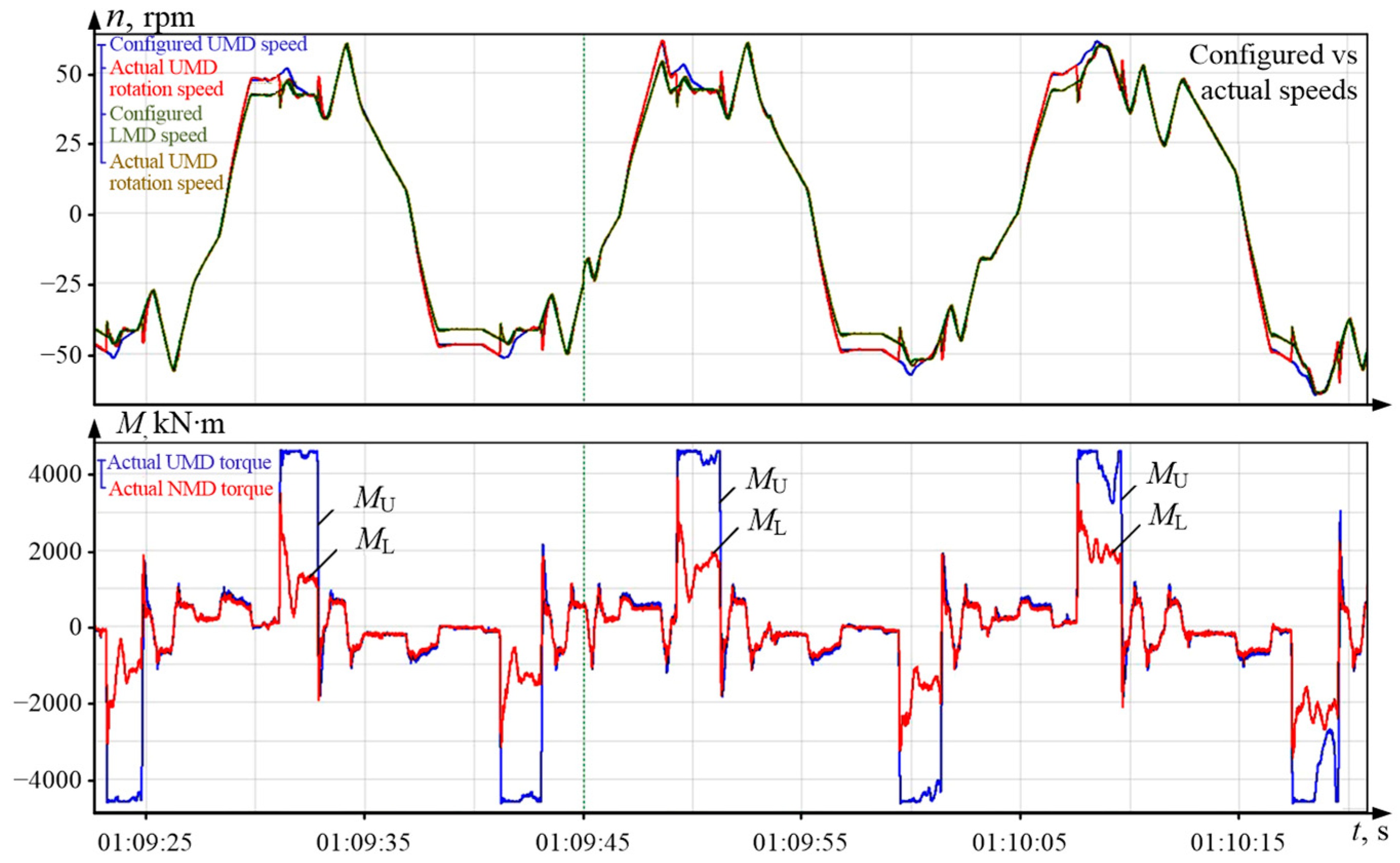
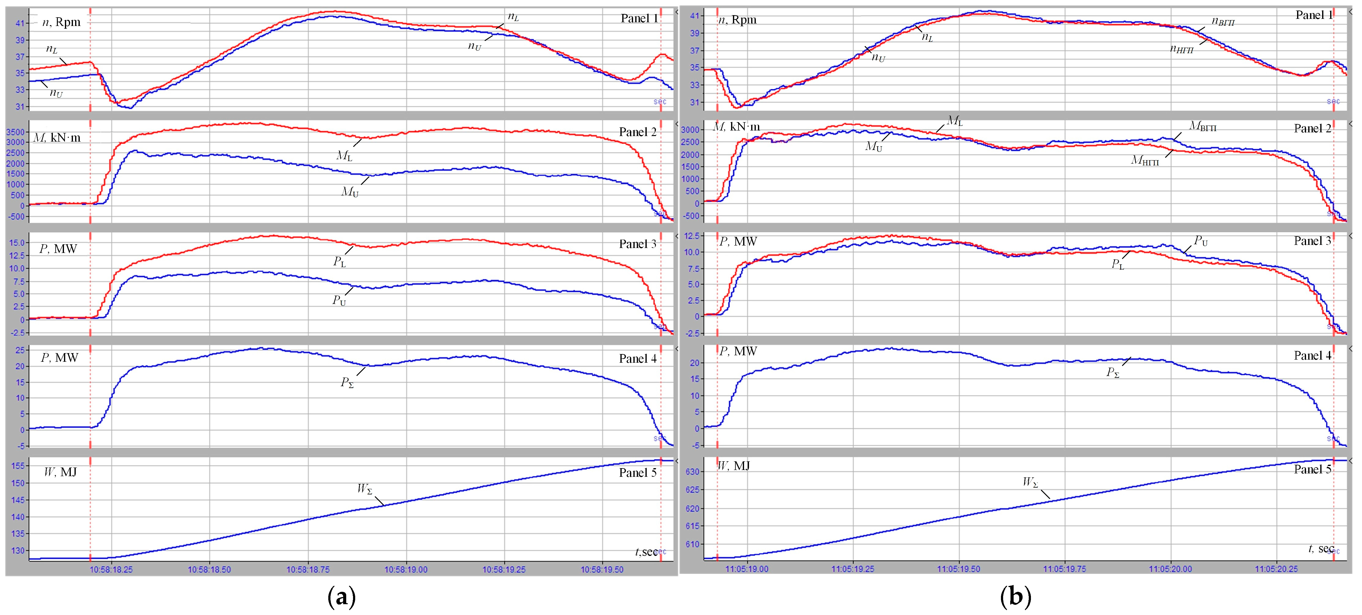
  • A speed misalignment of ±5% results in a 2× difference in torques while their ratios are opposite.
  • The no-ski state (zero-speed misalignment) provides almost complete alignment of torques.
  • During the first passes, the LDC is not activated, therefore torques are not aligned in Figure 7a.
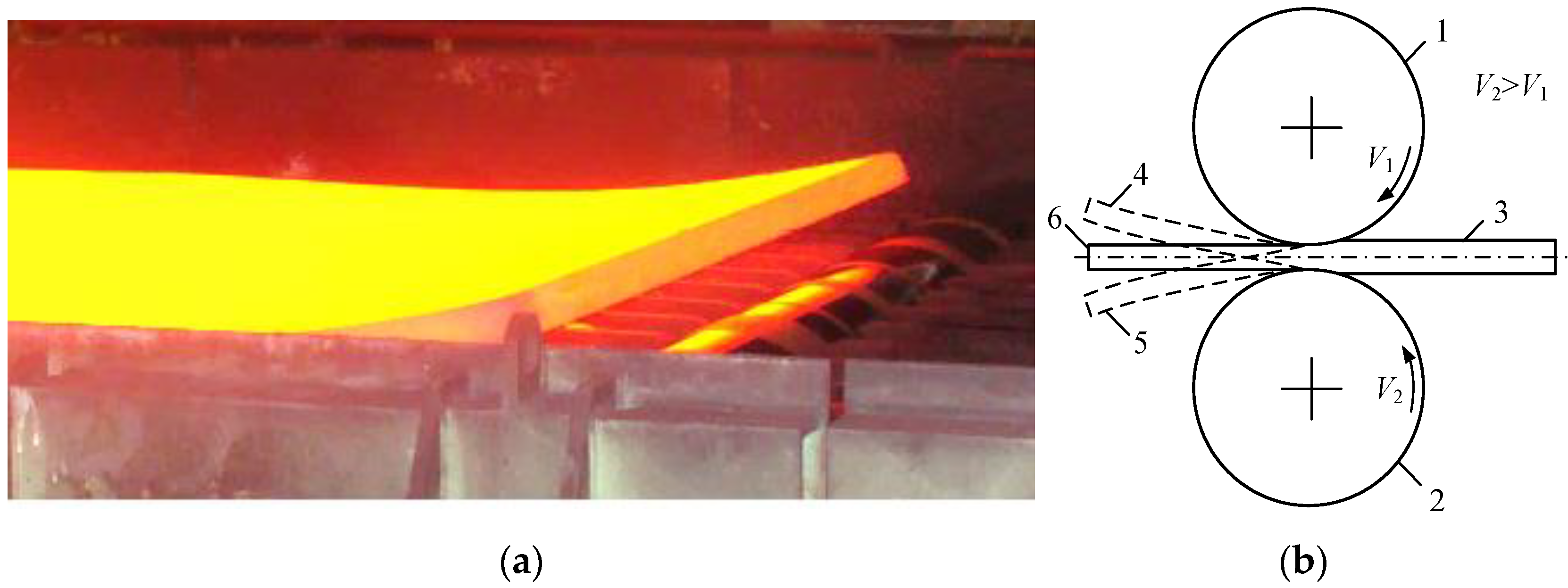
  • The misalignment of speeds shown in Figure 7a does not result in the desired bend of the workpiece front end (or it is not visible at least). However, this causes LMD motor overloading and UMD motor underloading resulting in multiple adverse effects.
The latter point shows that setting different speeds in roughing passes makes no practical sense. Therefore, we recommend performing roughing rolling with identical speed settings, i.e., preventing the ski formation. In the following passes, it is necessary to set a minimum speed misalignment that has to be adjusted as the workpiece thickness decreases. Thus, we recommend a rolling technology with a controlled ski setting. Experimental oscillograms obtained with this method are considered in Clause 4.3. In the same clause, we also calculate electricity losses with draft electric drive control algorithms for cases when the speeds and torques of UMD and LMD have no time to align. Before that, to develop an electricity loss observer, it is necessary to analyze the dependency of motor efficiency and load.

4.2. Dependency of Motor Efficiency and Load

The majority of publications utilize the dependency of electric drive efficiency and torque or current as they change from zero to the rated values. As mentioned before, the stand electric drives of the 5000 mill can operate in the load range of 0 to 2.4MN. Under greater loads, the motor enters the torque-limited mode. Thus, we need to express the dependency of efficiency and load for the set range.
The efficiency of any electrical machine can be calculated using Formulas (1) and (2). Electric power supplied to the motor:
P 2 = P 1 + Δ P L o s s ;
Power losses in the motor:
Δ P L o s s = Δ P S T + Δ P F + Δ P M e c h + Δ P M a g n + Δ P A D D ;
where Δ P S T is stator losses; Δ P F is rotor circuit losses; Δ P M e c h is mechanical losses; Δ P M a g n is magnetic losses in the stator and the rotor; Δ P A D D is additional losses.
Δ P S T = 3 R S T I S T 2 ;
Δ P F = R F I F 2 ;
R S T is the stator winding resistance;
R F is the excitation winding resistance;
I S T is the stator current;
I F is the excitation current.
Mechanical, magnetic, and additional losses put together make up about 1% of the motor’s rated power. Therefore, they are expressed as a constant and referred to as conditional–constant losses. For synchronous motor vector control purposes, when the process dynamics are neglected, the stator and excitation currents in speed control zone 1 are proportional to the load on the shaft [57]. This is illustrated by the oscillograms shown in Figure 8. Here, the oscillograms of the torque, stator current, and excitation current (panels 2, 3, and 4, respectively) are identical.
The oscillograms in Figure 9a were used to express the dependencies of the stator and excitation current and the torque over its range (0 to 2MN). These can be approximated with linear expressions:
I S T M = M · K I S ;
I F M = M · K I F + I F 0
where KIS = 2.2 and KIF = 422.4 are the line slope factors in Panels 1 and 2, respectively;
IF0 is the initial excitation current value in Panel 2 (600 A).
These were used along with expressions (1), (5)–(8) to make a curve of the dependency of efficiency and motor torque in Figure 9b. On the horizontal axis, we marked the relative values of the torque and used the rated torque MN as the base value. The chart suggests that the efficiency of the electric drive is at its maximum when loads are close to the rated value and drops when loads are smaller or greater. The efficiency values for three torque values are shown in Table 4. As the torque drops by 2.5 times (from MN to 0.4MN), the efficiency drops by 3% (from 0.968 to 0.94). As the load increases from rated to the permitted maximum of 2.4MN, this indicator decreases by 1.2%. Since the power of each motor is 12 MW, this seemingly small efficiency drop causes power losses of 14.4 kW (or 28.4 kW for two motors). Since the standard hot hour rate is 7000 h a year (with about half at non-rated loads), the annual electricity losses can exceed 100 MW h (or 1 × 10⁵ MJ), which will result in significant expenses for the company.
The detailed explanation for the approximation of the dependencies shown in panels 1 and 2 in Figure 9a with linear Equations (9) and (10) is not covered in this article. This is justified by visual assessment (the dependencies are visually linear). The justification would not add any additional information but increase the size of the article and therefore is omitted.
Below, we use the experimental results to provide a more accurate assessment of electricity losses.

4.3. The Experimental Assessment of Electricity Losses

Figure 10 shows the oscillograms of UMD and LMD speeds (Panel 1), torques (Panel 2), power ratings (Panel 3), total power (Panel 4), and power consumed for rolling (Panel 5). These were obtained when rolling identical workpieces for two cases: a 7% ski (Figure 10a), and a zero speed misalignment (Figure 10b).
The results of power loss and rolling power consumption calculations for these versions are given in Table 5. The efficiency values were calculated for each point with expression (1), then we calculated the average values shown in the table. The average power losses were calculated using expressions (7), (8). The total power losses for UMD and LMD are as follows:
-
no ski effect: 0.633 MW;
-
with a 7% ski effect: 0.752 MW.
Thus, the average power reduction achieved by speed alignment is 0.119 MW. This makes 18.9% of power losses during rolling with no ski effect and 15.8% of power losses at rolling with the set ski effect. Since the pass time in Figure 10 is 1.45 s, the average power loss difference is (0.119 × 1.45) = 0.172 MJ. This is confirmed by the significant electricity savings.
In the analysis, we took into account that the oscillograms were obtained for identical workpieces but at different times, i.e., at different initial conditions. Power is an integral parameter, which was therefore accumulated during the previous period. Thus, we did not consider the absolute values but the differences at the beginning and end of the analyzed period. Maximum power values in Panel 5 are as follows: 152 MJ in Figure 10a and 635 MJ in Figure 10b; and values at the beginning of passes are 125 MJ and 605 MJ, respectively. The total energy per pass in Table 5 was calculated as the difference of power values at the end and the beginning of passes. This is how we obtained values 27 and 28 MJ. The last lines of the table show the total consumed electric power and its reduction achieved by the alignment of UMD and LMD loads. The savings amount to 1 MJ or 3.7%.

5. Implementation

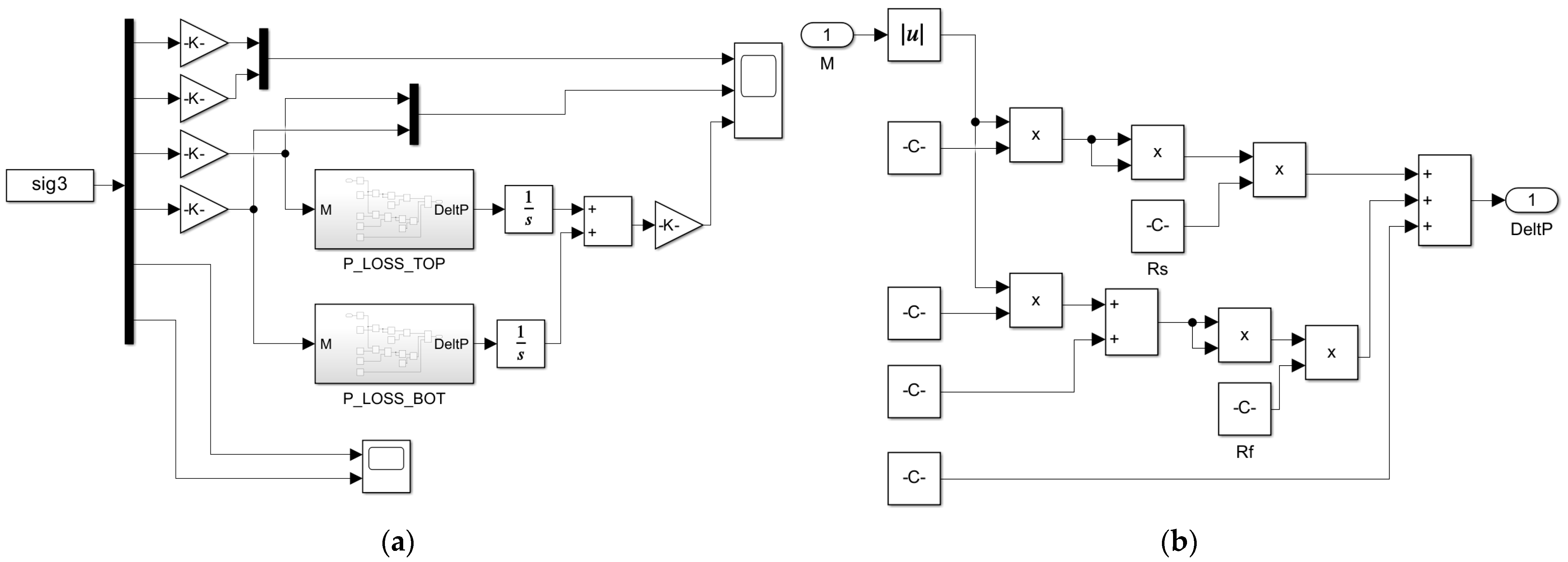
5.1. The Development of the Power Loss Observer

The conducted experimental research helped assess power and power losses per one pass. Obtaining the same information by processing oscillograms for more passes (e.g., the finishing stage of rolling) is complicated. Thus, to solve this problem, we suggest using the virtual processing of data received from the IbaPDA information and measurement system mentioned before. These data are read at a set increment and exported to Matlab for calculations. This way, we can perform the experimental analysis of the power parameters of the electric drive. The signal of electric power consumed by the motor is generated by the frequency converter. The mechanical power on the motor shaft is calculated as a product of the rotation rate and motor torque also calculated in the frequency converter. The mechanical power on the spindle is calculated as a product of speed and torque measured on the spindle by the torque probe. We use the torque observer mentioned above as this kind of spindle probe for the mill [28].
To analyze power parameters, we developed a dynamic model in Matlab Simulink shown in Figure 11a. It performed the efficiency and power observer functions. The observer input receives input data (motor speeds, torques, and power ratings) measured during rolling in the online mode. The efficiency and power ratings are calculated using Formulas (1) and (5)–(8). The flow chart of the power loss calculation block within the entire system is shown in Figure 11b. It calculates electricity losses caused by the passage of the stator and excitation currents calculated using Dependencies (9) and (10). Blocks <C> set constants KIS, KIF, and the initial value of magnetizing current IF0 = 600 A (see Figure 9a). Then, we perform calculations using expressions (7), (8): squaring, multiplication by RST = 0.03 Ohm and RF = 0.1 Ohm, etc.
Figure 12 shows oscillograms recorded on the mill in two subsequent reserve rolling passes. In the non-stationary modes of acceleration (period t1t2) and braking (period t3t4), the spindle torque and motor torque differ by a value equal to the difference between the dynamic motor torque and dynamic torque of load due to the inertia of rollers, workpiece, etc. Therefore, the mechanical power on the motor shaft and spindle shown in Panel 4 are different. Some of the motor power is spent on changing the kinetic energy reserves of the rotor. With the steady rolling rate (period t2t3), the motor torque MM and spindle torque MSP (Panel 2) are the same. These features are typical of almost all rolling mills because they support rolling with acceleration and braking.
The key feature of the provided figures is the efficiency oscillograms in Panel 5 obtained by observer calculations in the online mode. The efficiency dependency is identical to the stator current graph but the change trend is the opposite: as the current increases, the efficiency drops. This confirms the dominant impact of power losses on the electric drive efficiency. The oscillograms of stator current (Panel 3) and power (Panel 4) change almost synchronously. This nature of changes and the identical nature of oscillograms in Panels 2 and 3 confirm the point about the linear dependency between the stator current and the motor torque (see Figure 9a). The dynamic acceleration/braking modes (periods t1t2 and t3t4) feature different power ratings (Panel 4). In the quasi-steady rolling mode in the period t3t4, they are aligned. The same ratios can be found in Figure 12b.
We can claim that the recovered efficiency graphs for other passes shall have identical features with deviations that can be attributed to load current fluctuations. Therefore, analyzing efficiency in the online mode can be neglected. The analysis of electric power consumed for rolling, which can be used to calculate the losses that depend on efficiency) is a lot more practical. The recovered graphs of electric power consumption are shown below.
The results of electric drive parameter and power calculations for passes shown in Figure 10a,b are shown in Figure 13a,b, respectively. We provide the recovered (experimental) oscillograms of speeds (Panel 1), UMD and LMD motor torques (Panel 2), and consumed power (Panel 3). The speed and torque oscillograms are based on data arrays recorded during rolling. Electric power losses were calculated using the observer developed. Their analysis helps evaluate the total electric power consumption per pass:
-
for rolling with the set 7% ski effect (Figure 13a), it equals 1576 kJ;
-
for the no-ski case (Figure 13b), it is 1399 kJ.
The power savings amount to 177 kJ (0.177 MJ). This corresponds to the experimental value of 0.172 MJ obtained above in calculations with average values.

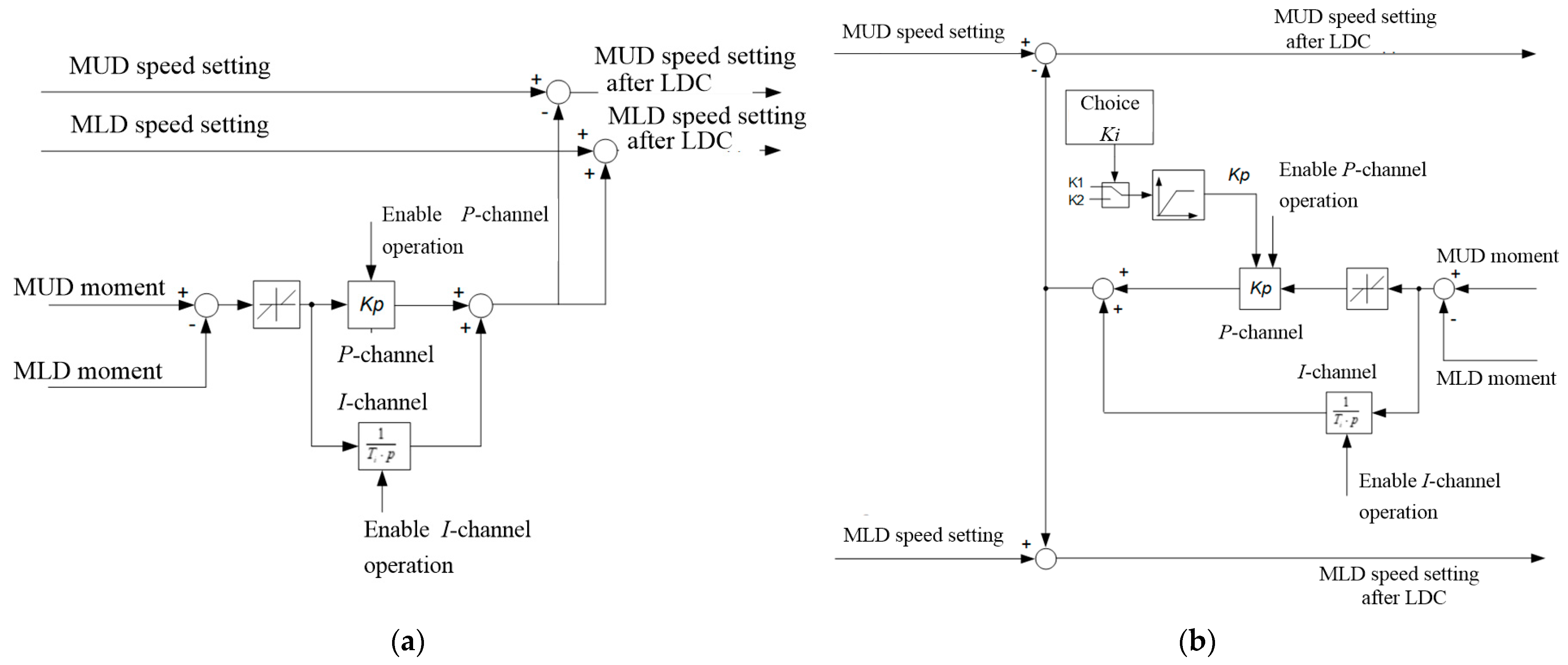
5.2. The Development of an Adaptable LDC

To reduce the torque alignment time, we developed a load alignment method that involves forced upper and lower roller electric drive speed alignment by isolating the integral LDC part and increasing the gain factor of the proportional part. When this process is complete, proportional-integral control of loads is attained in the steady mode to compensate for the speed misalignment, while the gain factor is switched to the calculated value. In the steady mode, misalignment adjustment is performed by summing the LDC output signal and the speed setting signals for the upper and lower roller electric drives with different operators as shown above in Figure 5.
Figure 14a shows a flow chart of the draft LDC that explains the UMD and LMD speed control method using the difference between the measured torques as reviewed in Clause 3.2. Figure 14b shows a diagram for an LDC with a switching structure explaining the developed method. In both diagrams, the controller comprises proportional (P) and integral (I) channels, but the specific feature of the suggested option is that the channels do not switch on simultaneously. Also, an adaptable LDC (Figure 14b) can switch the proportional channel gain factor KP.
In both cases, when MU > ML, the LDC output signal reduces the UMD speed and increases the LMD speed. When the torque ratio is reversed, i.e., ML > MU, the effects on the motor speeds are the opposite. The non-linear module with a deadband is designed to prevent speed adjustment when the misalignment of motor torques is small and the error is within the deadband. This improves the stability of control processes. Under the modes with no load control, the output LDC signal shall not be zero. To achieve this, an Enable P-channel operation signal is generated to disable (and subsequently enable) proportional channel operation.
When the workpiece is not in the rollers, gain factor selector KP is set with the value of factor K1 that is greater than the calculated factor for the pilot setting. This facilitates the forced alignment of UMD and LMD speeds so that the load alignment time is reduced. When the motor torque difference drops to 10% of the calculated value, the structure switches, and the lower value of gain factor K2 is set. Simultaneously, an Enable I-channel operation signal is generated to facilitate the astatic control of torque difference under the quasi-steady rolling mode. Thus, the developed LDC aligns the signals for channels P and I at different times. Forced proportional alignment helps increase the response rate, while the integral channel with a greater time constant facilitates zero alignment error under the steady mode.

5.3. Modeling Study

We developed a simulation model of the UMD and LMD linked through a workpiece with an adaptive LDC. It uses the structure shown in Figure 5. The parameters of links within a dual-mass system and speed controller were determined using the electrical equipment data and the oscillograms obtained on the mill. The calculation procedure and results are presented in [58]. The comparison of modeling and experimental results confirms the adequacy of the study object model. We proved the implementability of the developed technical solutions and the feasibility of using the model to study the forced load alignment method.
We used the developed model to study the UMD and LMD load alignment modes after the ski formation is complete. The typical processes obtained with the draft and newly developed LDC are shown in Figure 15a and Figure 15b, respectively. They display the dependencies of UMD and LMD speeds (Panel 1), torques (Panel 2), and speed differences (Panel 3). Torque scales are shown as percentages of the rated values, and the initial speed misalignment during the “ski” formation in both cases is set at a permitted maximum of 15%. The output signals of the LDC uL in both figures are shown in Panel 3.
In both cases, at a torque t1, the workpiece is gripped by the rollers, and the speed adjustment is performed over the interval Δt (Panel 1) to form the ski. The deceleration rate in this mode (Panel 3) is 16%/sec. Over the interval t2t3, torque alignment is performed (Panel 2), and Panel 3 shows signal uL. Processes in Figure 15b feature forced alignment of speeds over the said interval (Panel 1). Due to this, the alignment of torques MU and ML (Panel 2) occurs over a shorter period Δt5% compared to the processes in Figure 15a. The average parameters over the interval t2t3 during LDC operation are shown in Table 6.
Based on the analysis of these parameters, we could draw the following conclusions:
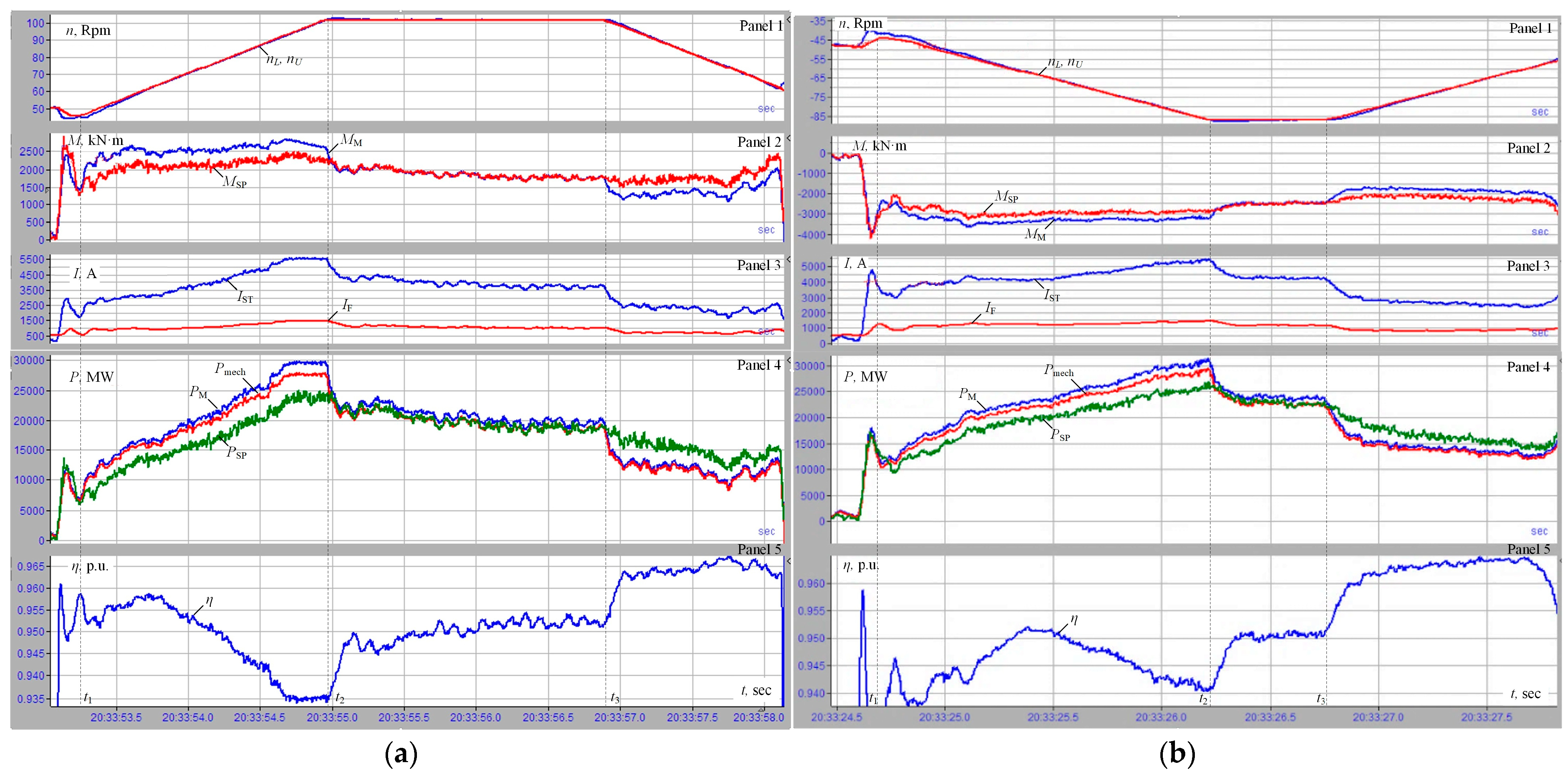
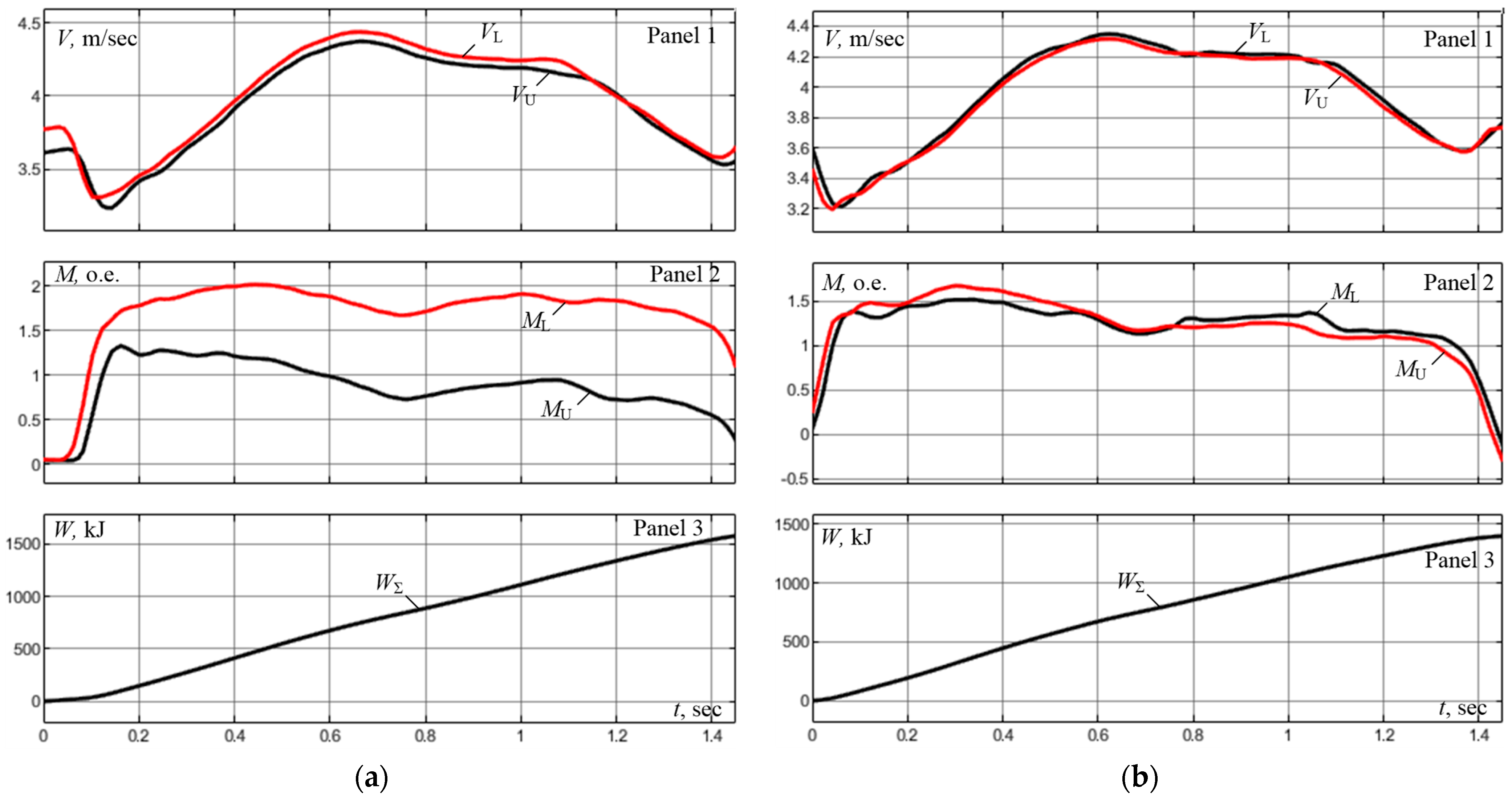
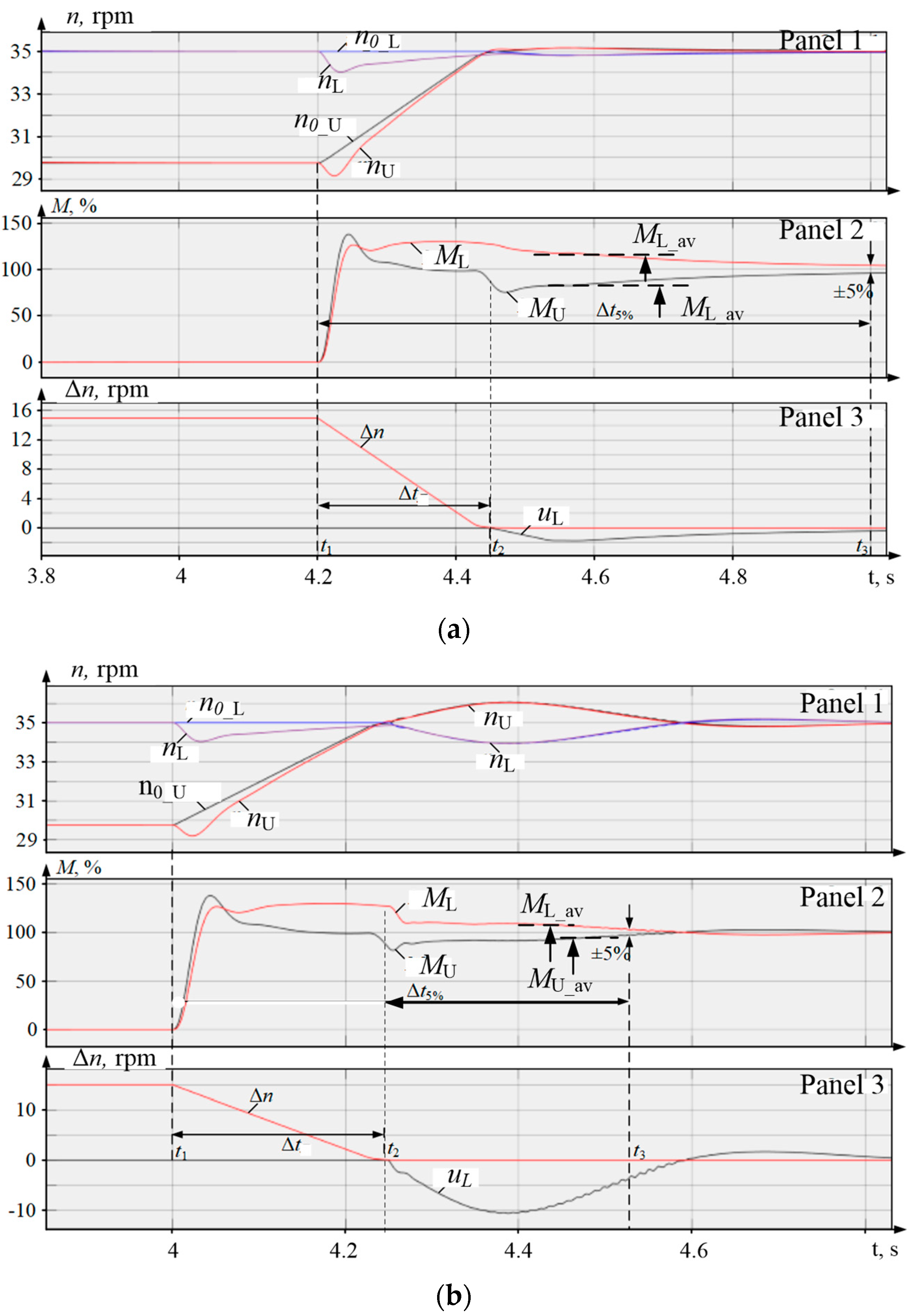
  • The steady misalignments of torques under the ski-formation mode over the interval t1t2 are identical and equal 30% (the LMD torque is 130% while the UMD torque is 100%). This can be attributed to the fact that the LDC does not operate in this interval.
  • The average difference of torques (ΔMav = ML_avMU_av) in the load alignment mode over the interval t2t3 is 40% in Figure 15a and 20% in Figure 15b, i.e., it is reduced by two times.
  • The arrival time for the 5% deviation zone of the steady torque of 100% is reduced by 2.1 times from Δt5% = 0.62 s to Δt5% = 0.3 s.
Thus, the results of modeling confirm the 2× reduction of torque alignment time due to forced output LDC signal adjustment. Therefore, the time for electric drives to enter the steady mode is reduced twice. Since the duration of speed alignment in roughing passes on the 5000 rolling mill makes up 50–80% of the rolling time, the reduction of the average load results in the improved thermal condition of the motor with a greater load.

6. Results

The algorithm implementing the suggested speed alignment method was deployed in the APCS of a 5000 mill. We also used the previously developed algorithm that reduced the ski-formation time [56]. Below, we present the results of the experimental assessment of electricity consumed during rolling.

6.1. The Analysis of Loads in Finishing Passes

Figure 16a shows oscillograms obtained in five finishing rolling passes using draft ski-formation and load division algorithms. Similar oscillograms obtained with the deployed algorithms are shown in Figure 16b. Rolling is performed with the same drafting in the same passes, which is confirmed by the identical rolling forces in Panel 3. In the first case, a 5% ski effect is set. The UMD and LMD speed setting oscillograms (Panel 1) do not show this setting as well as the difference of speeds nU and nL, due to the large scale.
Figure 16a shows torque (Panel 2) and current (Panel 4) misalignment in all passes except the first one. Before LDC activation, the current difference ranges between 1000 A in the second pass and 1500 A in the fourth and fifth passes. In the final passes, the LDC is activated at approximately half of the rolling interval. Therefore, the UMD and LMD currents are aligned closer to the end of rolling.
In Figure 16b, motor currents and torques in all passes are identical. The increased response rate of the adaptable LDC provides UMD and LMD load alignment in each pass. Current misalignment is virtually not observed except for the surges that occur when workpieces leave the stand.
Thus, the oscillograms confirm the effectiveness of the developed LDC with the switching structure. The deployment of the LDC helps reduce the power costs of rolling. This is accomplished by increasing electric drive efficiency and reducing the power required for ski formation. Below we provide experimental proof of this conclusion.

6.2. Power Costs Assessment for a Finishing Rolling Cycle

Figure 17 shows the dependencies of speeds (Panel 1), torques (Panel 2), and power (Panel 3) consumed at rolling. They are identical to the experimental oscillograms shown in Figure 13. These dependencies were drawn based on the experimental data recorded in 16 finishing rolling passes. Power calculations were conducted with an observer shown in Figure 14. Figure 17a illustrates rolling with a 7% initial speed difference. Therefore, the torque curves in Panel 2 differ by factor. Moreover, MU > ML in all passes except two last ones. In the last past, one the torques coincide, and in the last one their ratio changes to the opposite (MU < ML). In Figure 17b, the dependencies of load torques MU and ML coincide in all passes.
The analysis of these dependencies makes us draw the following conclusions:
-
the power consumed for rolling equals 93,920 kJ in the first case (Figure 17a) and 88,590 kJ in the second case (Figure 17b);
-
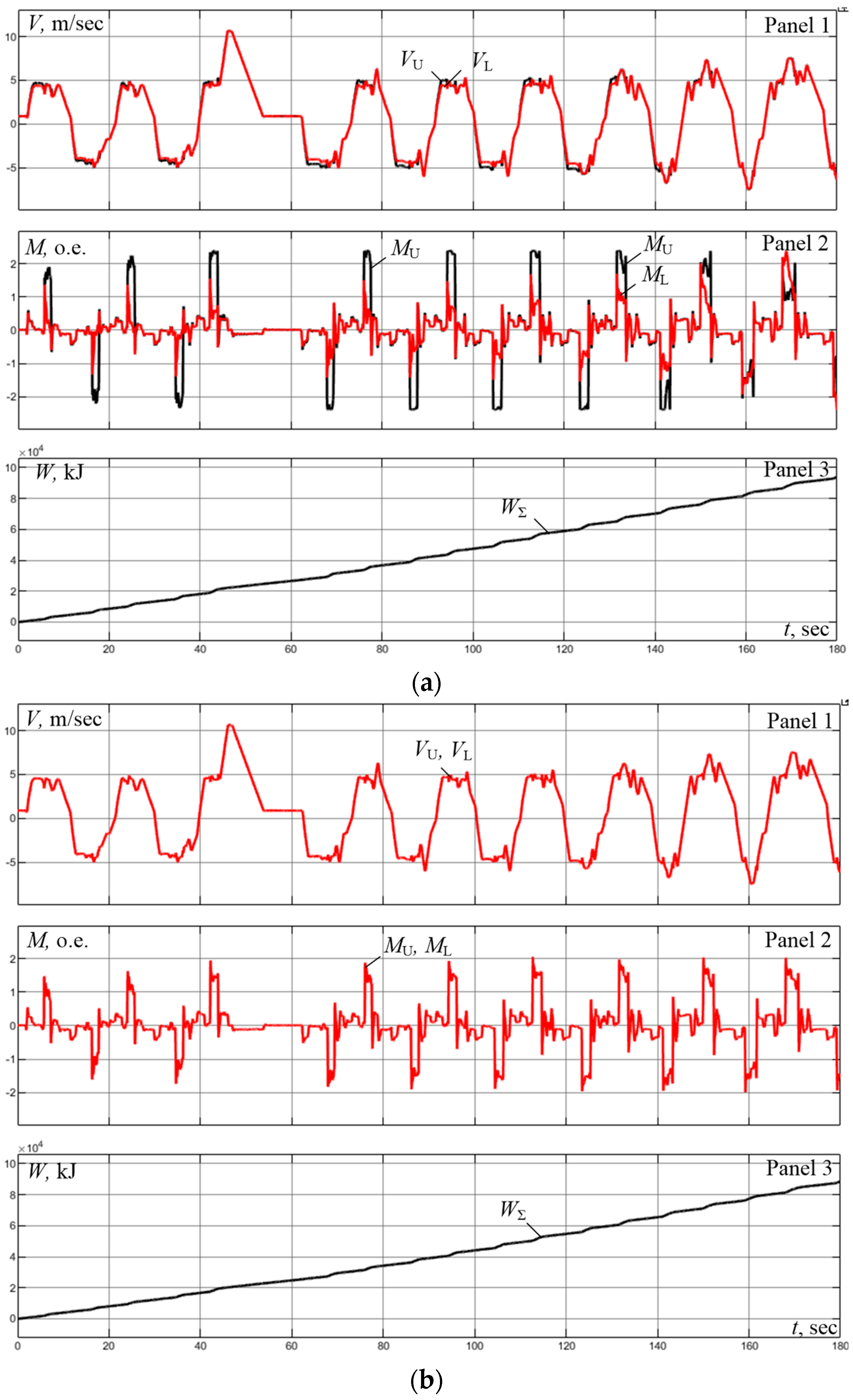
the difference in power costs for the 180 s rolling cycle in question is 5330 kJ (1.48 kWh) or 5.7%.
This power consumption reduction is the maximum possible for the rolling modes under analysis. It is achieved when motor torques are the same in each pass. In practice, rolling with perfectly identical speeds and torques is rare. However, we can claim that the deployment of the developed LDC can help reduce the time during which the UMD and LMD operate with uneven loads. This is confirmed by the calculation dependencies in Figure 15 and oscillograms in Figure 16.
The declared power savings are calculated based on the experimental data recorded on the mill. The standard oscillograms used in calculations are shown in Figure 17. As a result, we provided a power savings assessment compared to the actual power consumed by the electric drives of the stand. These results can be achieved following the implementation of the developed control algorithms. The comparison with the theoretical results that could be achieved with other load-balancing methods is irrelevant.

7. Summarizing Research Results and Prospects

The developed load alignment algorithm with an adaptable LDC is used in a 5000 mill. The advantages of rolling include forced motor torque alignment and an increase in the electric drive efficiency. We obtained a large number of oscillograms that confirm the accomplishment of these results.

7.1. Summary of the Deployment Results

For illustrative purposes, Figure 18 shows oscillograms obtained after the improvement of roller electric drive control algorithms, which included the deployment of an adaptable LDC and the ski-formation algorithm mentioned above [56]. Figure 18a shows the oscillograms of speeds (Panel 1), motor torques (Panel 2), set thickness h0 and current thickness h (Panel 3), as well as ski setting oscillograms Δn,% (Panel 4). These were obtained during the rolling cycle for a 3250 mm-thick 09G2S steel workpiece, which is not classified as heavy. The cycle duration is 11 min. Due to the improved algorithms, it is possible to set different speed misalignments for passes. The ski setting is 3% in roughing passes and 1% in finishing passes. During rolling, the operators do not adjust the speed settings (Panel 4). This makes us draw the conclusion that the required curvature of the front end of the workpiece can be achieved with a smaller UMD and LMD speed misalignment. As shown in Clause 5.3 (Figure 15), this provides for faster torque alignment.
The performed analysis confirmed the reduction of electricity losses by 3.5% (calculated the same way as in Clause 6.2). This parameter is lower than the loss reduction calculated for the case shown in Figure 17 (5.7%). This can be attributed to the impossibility of achieving the perfect alignment of torques shown in Figure 17 in real life. This conclusion is confirmed by the finishing phase oscillograms shown in Figure 18b. They suggest that during the first passes, alignment only takes place in part of the pass interval. Figure 15 shows that the uneven load period may take up to half of the pass time. In this case, the electricity loss reduction would be 2.85%. Thus, the achieved 3.5% is a satisfactory result.
Overall, the oscillograms shown in Figure 18 confirm the technical effectiveness of deploying the development in achieving the goal set.
The operation and experimental research of the introduced system were carried out throughout a year. The efficiency of the obtained results is confirmed in practice. There is no need for additional experiments to assess the statistics (variance/error margins, etc.).

7.2. Further Research Prospects

The developed observer helps visualize motor efficiency which is calculated based on data arrays recorded over a long time. This possibility is the most valuable for the optimization of rolling programs to minimize the power costs of rolling. It is also feasible to analyze efficiency when developing programs for new rolled product types. These are relevant problems that can be solved in further research.
The calculation of electricity losses using data arrays made for each pass helps solve the following problems:
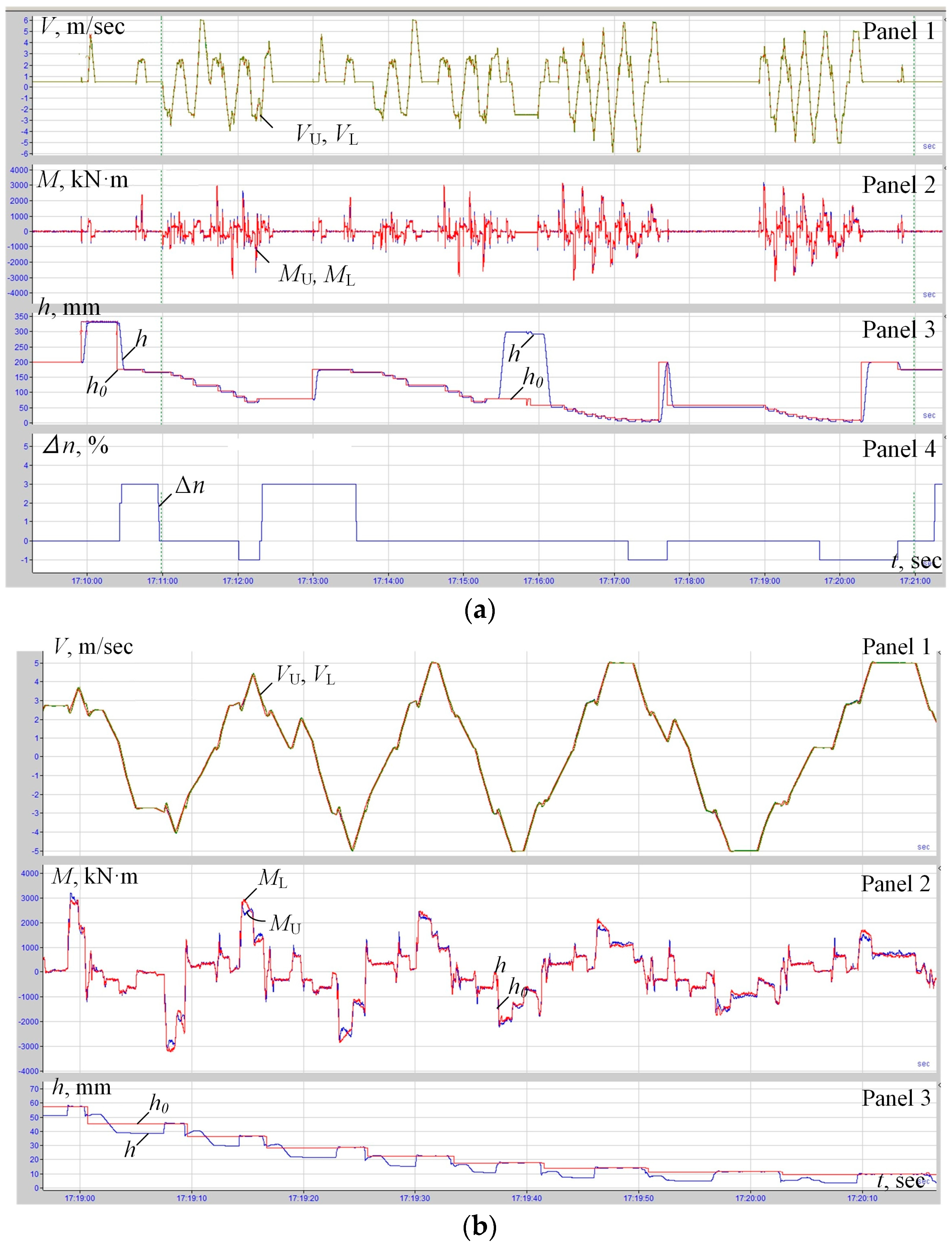
  • Optimizing speed mode for each pass by setting the optimal acceleration and deceleration rates, which is relevant for both plate mills and continuous rolling mills [59]. According to the oscillograms in Figure 12, efficiency is higher in steady rolling modes than during acceleration under load (Panel 5). In this case, the power graphs shown in Panel 4 are identical, and power losses are therefore at the minimum. Thus, the possibility of efficiency analysis helps optimize the ratio of dynamic and steady-state intervals to help reduce power and electricity losses. This can also be achieved by selecting the optimal acceleration and deceleration rates.
  • The knowledge of efficiency may be useful when optimizing rolling programs for the existing product types or when developing programs for new types of rolled products. The procedures and examples of such solutions are studied in [60,61]. This can be effective when launching the production of sheets made of difficult-to-form grades of steel used for the production of large-diameter pipes. Since the share of such products is constantly increasing, any power loss reduction can have a significant effect on the factory and the sector.
The conducted analysis suggests that the value of losses is a goal function with several variables. Mathematical description and discovering functional minimums are not simple tasks [62] and can therefore make a subject matter of dedicated research. In this case, the possibility of analyzing electricity losses and efficiency can be useful. Thus, the developed power parameter observer with the efficiency calculation function should be used in electric drives of various rolling mills.
The next area of research is the improvement of the LDC response rate by using fuzzy logic (FL) algorithms. FL is a powerful mathematical tool that can improve the precision of parameter adjustment. Developing an LDC with FL shall require its synthesis, which is non-trivial in a scenario with two electric drives with different loads and a non-linear link via the workpiece. This shall require simulation modeling research, virtual adjustment, and experiments on the object. The prospects of this solution are based on reference items [23,36,38,39]. However, this problem is not solved for rolling mills. This problem requires additional study, but the approach to its solution is outlined in this article. The suggested experimental analysis procedure is deemed adequate for electric drive research with a fuzzy LDC. The preliminary analysis showed that the expected motor torque alignment time will be reduced by 1.5 times in this case. When analyzing the power consumed for rolling using the procedure presented in Clause 6.2, the expected electricity cost reduction amounts to 1.5–2%. In this case, the reduction of power losses is at least 18%. Consider paper [63] that confirms the authors’ research experience in this area.
Moreover, the reduction of motor overloads shall help prolong their service life. This shall happen due to the reduced insulation wear, which depends on the current and, consequentially, the motor temperature. There are several service life calculation methods, particularly [14,15]. However, the majority of these methods use equivalent circuits (their drawbacks were discussed above). Moreover, the incremental nature of loading and motor cooling between passes is not considered. Therefore, it is feasible to develop a service life calculation procedure based on the data saved as arrays during rolling. It must be simple and applicable to operating equipment.
The experimental research procedure presented in this article is accessible to metal plant personnel. Research does not require complex algorithms, specialized software, or extra training.
Apart from energy efficiency improvement, the alignment of upper and lower roller loads increases the service life of motors. This is because equal loads help reduce equivalent currents (or torques) of the motors, which has a positive effect on their thermal conditions. This problem was considered in [13] by the authors, where we developed a calculation methodology for equivalent loads that facilitates automated motor heating tests based on the data obtained during rolling. In the case of unique and cost-intensive 5000 mill motors, even slight service life increases due to reduced thermal loads can provide significant technological and financial benefits. This effect can be achieved without additional capital investment due to the reduction of costs associated with motor maintenance, repair, and replacement. This problem can be studied in a specific publication.
This research produced the following innovation points:
  • The impact of rolling stand motor speed misalignment on their electromagnetic torques in the quasi-steady rolling mode was studied for the first time. The experiments showed that a 5% difference in speeds results in a three times difference in UMD and LMD motor torques. One of the reasons for this is the bending of the front end of the workpiece (the ski effect)
  • The authors were the first to study the impacts of rolling stand motor load misalignment on the efficiency and the losses of electric power. The total power losses at a 7% speed misalignment equal to about 19% of the power losses during rolling, which is unacceptable.
  • We developed a motor electricity loss and efficiency monitor. We analyzed the efficiency oscillograms (Figure 12) produced through the monitor recovery in the online mode. We confirmed the overwhelming impact of electricity losses on the efficiency of the electric drive and the linear dependency of the stator current and the motor torque.
  • We developed and studied a load alignment method for the UMD and LMD motors of a plate rolling mill stand. A load division controller with a switching structure that facilitates the implementation of the method in question was deployed in industrial settings. The technological and financial effects of power loss reduction due to its operation are confirmed.
The obtained results suggest that the conducted research has important theoretical and practical results.

8. Conclusions

  • We stressed the importance of energy saving in the most energy-intensive industrial sector, ferrous metallurgy. Significant electricity savings can be achieved by increasing the efficiency of high-power electric drives of rolling mills. When analyzing the experimental oscillograms of the 5000 plate mill electric drives, we showed the multi-factor difference between the upper and lower roller motors, which results in reduced efficiency.
  • The review of publications confirmed the impact of load on the efficiency of frequency-controlled electric drives. We considered the known efficiency calculation methods with partial speed and changing loads and identified their drawbacks. We justified the development of an efficiency and electric loss observer that calculates these parameters in the online mode. We gave the rationale for the experimental analysis of power parameters that help process the signals recorded in data arrays. Following the analysis of publications, we confirmed the feasibility of developing an electric drive control method to facilitate load alignment between the upper and lower roller motors of a rolling stand with a high response rate.
  • We described the horizontal stand electric drives of the 5000 mill. It is fitted with 12 W synchronous motors with frequency speed control. We showed that the difference in UMD and LMD motor torques is caused by the speed misalignment required for ski formation. A load division controller designed for torque alignment cannot facilitate the required response rate and is not activated during the first passes. Experiments confirm that when the speed difference is ±5% in the steady state, the difference between UMD and LMD motor torques is triple. This results in increased power losses due to the reduction of efficiency.
  • The efficiency of the stand electric drive was analyzed, and its reduction was confirmed when loads were above the rated value. The total power losses at a 7% speed misalignment equal 0.633 MW or 18.9% of the power losses during rolling with zero-misalignment. We developed an electric drive electricity loss and efficiency observer. It is a program in Matlab Simulink that facilitates the calculation of these parameters in the online mode or using data arrays recorded during rolling.
  • We developed a load alignment method that involves forced upper and lower roller electric drive speed alignment by isolating the integral LDC part and increasing the gain factor of the proportional part. We presented a load division controller with a switching structure that facilitates the implementation of the method in question. Research carried out with modeling confirmed the 2× reduction of torque alignment time.
  • The algorithm implementing the suggested speed alignment method in the steady state was deployed in the APCS of a 5000 mill. We performed a comparative analysis of oscillograms obtained during an 11 min rolling cycle with the existing and deployed ski-formation and load-division algorithms. The confirmed electricity loss reduction was 3.5%.
  • The analysis of losses over a long operating period confirmed the technical effectiveness of deploying the developments. Further research prospects include the optimization of speed modes for each pass (by setting the optimal acceleration and deceleration rates) and developing rolling programs for new product types. In these cases, the deployment of the efficiency observer can improve the precision of power loss assessment. The development of an LDC based on the fuzzy logic methods is also a relevant goal.
  • The developed load alignment method and load-division controller with a switching structure used for the implementation of the method should be used in the electric drives of the operating rolling mills. Their use involves individual electric drives for the upper and lower stand rollers and the ski formation mode. The specific modules to be fitted with the developed solutions include roughing stands of hot-rolled plate mills and bar and shape mills, as well as stands of some pipe-rolling mills. The general nature of the approach is facilitated due to the similarity of the rolling technology and loading modes of the electric drives. A more accurate assessment of efficiency metrics will require additional research in each specific case.

Author Contributions

Conceptualization, A.S.K., A.A.R. and B.M.L.; methodology, S.S.V. and M.A.Z.; software, R.A.L. and M.A.Z.; validation, B.M.L. and I.N.E.; formal analysis, V.R.K. and I.N.E.; writing—original draft preparation, A.S.K., S.S.V. and R.A.L.; writing—review and editing, S.S.V. and V.R.K.; visualization, V.R.K. and I.N.E.; supervision, A.S.K., A.A.R. and B.M.L. All authors have read and agreed to the published version of the manuscript.

Funding

This work was financially supported by the Moscow Polytechnic University within the frame-work of the grant named after Pyotr Kapitsa.

Data Availability Statement

Data are contained within the article.

Conflicts of Interest

The authors declare no conflicts of interest.

References

  1. Brusa, E.; Delprete, C.; Giorio, L. Smart Manufacturing in Rolling Process Based on Thermal Safety Monitoring by Fiber Optics Sensors Equipping Mill Bearings. Appl. Sci. 2022, 12, 4186. [Google Scholar] [CrossRef]
  2. Orcajo, G.A.; Rodríguez, D.J.; Cano, J.M.; Norniella, J.G.; Ardura, G.P.; Llera, T.R.; Cifrián, R.D. Dynamic estimation of electrical demand in hot rolling mills. In Proceedings of the 2015 IEEE Industry Applications Society Annual Meeting, Addison, TX, USA, 18–22 October 2015; pp. 1–9. [Google Scholar] [CrossRef]
  3. Du, R.; Liu, Z.; Ge, L.; Cui, J.; He, L. A New Electrohydraulic Hybrid Energy-Saving System Used on the Reversible Rolling Mills. Adv. Mater. Sci. Eng. 2023, 2023, 1–17. [Google Scholar] [CrossRef]
  4. Szemmelveisz, T.; Kun, E. Energy efficiency enhancement in the Hot Rolling Mill. Mater. Sci. Eng. 2014, 3, 43–50. Available online: https://matarka.hu/koz/ISSN_2063-6792/vol_39-2_2014_eng/ISSN_2063-6792_vol_39_2_2014_eng_043-050.pdf (accessed on 22 February 2025).
  5. Kuznetsov, K.B.; Gorozhankin, A.N.; Funk, T.A.; Khusainov, S.N.; Kruglov, G.A.; Korzhov, A.V. Ways to decrease losses in electric drives and improvement of electrical safety during their service. Russ. Electr. Eng. 2017, 88, 209–211. [Google Scholar] [CrossRef]
  6. Karandaev, A.S.; Khramshin, V.R.; Khramshin, R.R.; Barankova, I.I. Conceptual Area of Development of Power Saving Thyristor Electric Drives of Rolling Mills. Procedia Eng. 2016, 150, 3–10. [Google Scholar] [CrossRef]
  7. Usynin, Y.S.; Shishkov, A.N.; Sychev, D.A.; Savosteenko, N.V.; Khayatov, E.S. Improving the energy efficiency of electric drives of reciprocating rolling mills. Russ. Electr. Eng. 2015, 86, 709–711. [Google Scholar] [CrossRef]
  8. Holtz, J.; da Cunha, G.; Petry, N.; Torri, P.J. Control of Large Salient-Pole Synchronous Machines Using Synchronous Optimal Pulsewidth Modulation. IEEE Trans. Ind. Electron. 2015, 62, 3372–3379. [Google Scholar] [CrossRef]
  9. Gasiyarov, V.R.; Maklakov, A.S.; Lisovski, R.A. Grid power control by medium voltage AC drives based on back-to-back converters. In Proceedings of the 2018 IEEE Conference of Russian Young Researchers in Electrical and Electronic Engineering (EIConRus), Moscow and St. Petersburg, Russia, 29 January–1 February 2018; pp. 629–631. [Google Scholar] [CrossRef]
  10. Variable Frequency Drives. Energy Efficiency Reference Guide. Available online: https://natural-resources.canada.ca/energy-efficiency/energy-star/variable-frequency-drives (accessed on 22 February 2025).
  11. Power Parameters of the Electric Drive Based on a Frequency Controller. Available online: https://www.artesk.ru/invertor_ikonom.html (accessed on 22 February 2025).
  12. Yu, J.; Zhang, T.; Qian, J. Testing methods for electric motors. Electr. Mot. Prod. 2011, 6, 95–172. [Google Scholar] [CrossRef]
  13. Voronin, S.S.; Radionov, A.A.; Karandaev, A.S.; Erdakov, I.N.; Loginov, B.M.; Khramshin, V.R. Justifying and Implementing Concept of Object-Oriented Observers of Thermal State of Rolling Mill Motors. Energies 2024, 17, 3878. [Google Scholar] [CrossRef]
  14. Metelkov, V.P. Estimation of a resource of induction motors stator winding insulation in cyclic operation. Bulletin of the South Ural State University. Ser. Power Eng. 2013, 13, 96–100. Available online: https://www.powervestniksusu.ru/index.php/PVS/article/view/424 (accessed on 22 February 2025).
  15. Zyuzev, A.M.; Metelkov, V.P. Toward the Evaluation of the Thermal State of an Induction Motor in the Recursive Short-Term Mode. Russ. Electr. Eng. 2014, 85, 554–558. [Google Scholar] [CrossRef]
  16. Braslavsky, I.Y.; Ishmatov, Z.S.; Polyakov, V.N. Energy-Saving Asynchronous Electric Drive; Akademia: Moscow, Russia, 2004; p. 202. [Google Scholar]
  17. Lee, S.; Son, Y. Motor Load Balancing with Roll Force Prediction for a Cold-Rolling Setup with Neural Networks. Mathematics 2021, 9, 1367. [Google Scholar] [CrossRef]
  18. Jin, X.; Li, C.; Wang, Y.; Li, X.; Xiang, Y.; Gu, T. Investigation and Optimization of Load Distribution for Tandem Cold Steel Strip Rolling Process. Metals 2020, 10, 677. [Google Scholar] [CrossRef]
  19. Zhao, H.; Chen, W.; Qu, F.; Chen, H. Research on power balance of multi-motor drive for mining belt transportation. In Proceedings of the 7th International Conference on Electronic Technology and Information Science (ICETIS), Harbin, China, 21–23 January 2022; pp. 1–5. Available online: https://ieeexplore.ieee.org/document/9788591 (accessed on 22 February 2025).
  20. Hu, Z.; Yang, J.; Zhao, Z.; Sun, H.; Che, H. Multi-objective optimization of rolling schedules on aluminum hot tandem rolling. Int. J. Adv. Manuf. Technol. 2016, 85, 85–97. [Google Scholar] [CrossRef]
  21. Wang, D. Load Balance Control of Top/Bottom WRs for Single Stand Reversing Cold Mill. CFHI Technol. 2009, 131, 32–35. (In Chinese) [Google Scholar]
  22. Yang, J.; Su, B.; Chen, L.; Zhang, J. Load Balance Control of Mill Driving System. Metall. Equip. 2013, 202, 5–10. (In Chinese) [Google Scholar]
  23. Weizheng, L.; Ming, Z.; Ruicheng, Z.; Ying, S. The Research on Load Balance Controller of Roller Single Roller Drive System Based on Fuzzy PID. In Proceedings of the 2020 Chinese Control And Decision Conference (CCDC), Hefei, China, 22–24 August 2020; pp. 5255–5260. [Google Scholar] [CrossRef]
  24. Yang, Z.; Liu, D.; Zhang, X.; Huang, W.; Zheng, G.; Liu, M. Optimization of Rolling Schedule for Single-Stand Reversible Cold Rolling Mill Based on Multiobjective Artificial Fish Swarm Algorithm. Wirel. Commun. Mob. Comput. 2022, 2022, 1–15. [Google Scholar] [CrossRef]
  25. Wang, G. Preliminary Investigations of the Impact of Variable-Frequency Drive (VFD) Output Voltage on Motor Efficiency. ASHRAE Trans. 2019, 125, 696–702. [Google Scholar]
  26. Li, Y.; Liu, M.; Lau, J.; Zhang, B. A novel method to determine the motor efficiency under variable speed operations and partial load conditions. Appl. Energy 2015, 144, 234–240. [Google Scholar] [CrossRef]
  27. César da Silva, J.; Leite de Vasconcelos Lima, T.; de Lucena Júnior, J.A.; Jordão Lyra, G.; Vidal Souto, F.; de Souza Pimentel, H.; Antônio Belo, F.; Cavalcante Lima Filho, A. Non-Invasive Method for In-Service Induction Motor Efficiency Estimation Based on Sound Acquisition. Appl. Sci. 2020, 10, 3757. [Google Scholar] [CrossRef]
  28. Gasiyarov, V.R.; Radionov, A.A.; Loginov, B.M.; Karandaev, A.S.; Gasiyarova, O.A.; Khramshin, V.R. Development and Practical Implementation of Digital Observer for Elastic Torque of Rolling Mill Electromechanical System. J. Manuf. Mater. Process. 2023, 7, 41. [Google Scholar] [CrossRef]
  29. Sujeeth, A.; Di Cataldo, A.; Tornello, L.D.; Pulvirenti, M.; Salvo, L.; Sciacca, A.G.; Scelba, G.; Cacciato, M. Power Loss Modelling and Performance Comparison of Three-Level GaN-Based Inverters Used for Electric Traction. Energies 2024, 17, 595. [Google Scholar] [CrossRef]
  30. Chilikin, M.G.; Sandler, A.S. A Guideline to Electric Drives; Energoizdat: Moscow, Russia, 1981; p. 576. [Google Scholar]
  31. Chayakulkheeree, K.; Hengsritawat, V.; Nantivatana, P. Particle Swarm Optimization Based Equivalent Circuit Estimation for On-Service Three-Phase Induction Motor Efficiency Assessment. Eng. J. 2017, 21, 101–110. [Google Scholar] [CrossRef]
  32. Bonaldi, E.L.; Lambert-Torres, G.; Salomon, C.P.; Cortez, A.D.; da Silva, J.G.B.; da Silva, L.E.B.; Oliveira, L.E.D.L.D.; Santana, W.C. Differential Evolution based Air-Gap Torque method approach for induction motor efficiency estimation. In Proceedings of the 2015 18th International Conference on Intelligent System Application to Power Systems (ISAP), Porto, Portugal, 11–16 September 2015; pp. 1–6. [Google Scholar] [CrossRef]
  33. Jangjit, S.; Laohachai, P. Parameter Estimation of Three-Phase Induction Motor by Using Genetic Algorithm. J. Electr. Eng. Technol. 2009, 4, 360–364. [Google Scholar] [CrossRef]
  34. ibaPDA Scalable Basic Software for Measured Data Collection. Available online: https://www.iba-ag.com/en/ibapda (accessed on 22 February 2025).
  35. Niu, F.; Sun, K.; Huang, S.; Hu, Y.; Liang, D.; Fang, Y. A Review on Multimotor Synchronous Control Methods. IEEE Trans. Transp. Electrif. 2023, 9, 22–33. [Google Scholar] [CrossRef]
  36. Jerkovic Stil, V.; Varga, T.; Bensic, T.; Barukcic, M. A Survey of Fuzzy Algorithms Used in Multi-Motor Systems Control. Electronics 2020, 9, 1788. [Google Scholar] [CrossRef]
  37. Ristic, L.; Bebic, M.; Jetvic, D.; Jeftenic, B.; Statkic, S.; Nikolic, A. Controlled multi motor drives of high power belt conveyors: Practical experiences during the exploitation of the system on open pit mine. In Proceedings of the 13th WSEAS International Conference on Electric Power Systems, High Voltages, Electric Machines (POWER 13), Chania, Greece, 27–29 August 2013; pp. 65–70. [Google Scholar]
  38. Jerkovic Stil, V.; Varga, T.; Bensic, T.; Barukcic, M. Fuzzy Algorithms in Multi-Motor Systems. Encyclopedia. Available online: https://encyclopedia.pub/entry/3013 (accessed on 15 February 2025).
  39. Ikeda, H.; Hanamoto, T. Fuzzy controller of multi-inertia resonance system designed by Differential Evolution. In Proceedings of the International Conference on Electrical Machines and Systems (ICEMS), Busan, Republic of Korea, 26–29 October 2013; pp. 2291–2295. [Google Scholar] [CrossRef]
  40. Fan, L.P.; Liu, Y. A Control Method for Load Balance between Upper and Lower Roll of Four-High Hot Rolling Mill. Appl. Mech. Mater. 2014, 687–691, 167–170. [Google Scholar] [CrossRef]
  41. Yang, J.M.; Su, B.; Lv, J.; Che, H.J. The improved load balance adjustor of multi-motor driving system. In Proceedings of the 32nd Chinese Control Conference, Xi’an, China, 26–28 July 2013; pp. 5305–5310. Available online: https://ieeexplore.ieee.org/document/6640363 (accessed on 15 February 2025).
  42. Zhu, C.; Tu, Q.; Jiang, C.; Pan, M.; Huang, H. A Cross Coupling Control Strategy for Dual-Motor Speed Synchronous System Based on Second Order Global Fast Terminal Sliding Mode Control. IEEE Access 2020, 8, 217967–217976. [Google Scholar] [CrossRef]
  43. Chen, W.; Yifei, W.; Du, R.; Chen, Q.; Wu, X. Speed Tracking and Synchronization of a Dual-Motor System via Second Order Sliding Mode Control. Math. Probl. Eng. 2013, 2013, 919837. [Google Scholar] [CrossRef]
  44. Kucsera, P.; Beres, Z. Hot Rolling Mill Hydraulic Gap Control (HGC) thickness control improvement. Acta Polytech. Hung. 2015, 12, 93–106. Available online: https://acta.uni-obuda.hu/Kucsera_Beres_62.pdf (accessed on 15 February 2025).
  45. Zhang, F.; Zhang, Y.; Hou, J.; Wang, B. Thickness control strategies of plate rolling mill. Int. J. Innov. Comput. Inf. Control. 2015, 11, 1227–1237. [Google Scholar]
  46. Zhang, F.; Zhang, Y.; Chen, H. Automatic Gauge Control of Plate Rolling Mill. Int. J. Control. Autom. 2016, 9, 143–156. [Google Scholar] [CrossRef]
  47. Radionov, A.A.; Gasiyarov, V.R.; Karandaev, A.S.; Loginov, B.M.; Khramshin, V.R. Advancement of Roll-Gap Control to Curb the Camber in Heavy-Plate Rolling Mills. Appl. Sci. 2021, 11, 8865. [Google Scholar] [CrossRef]
  48. Hu, X.; Zhang, D.; Tan, R.; Xie, Q. Controlled Cooling Temperature Prediction of Hot-Rolled Steel Plate Based on Multi-Scale Convolutional Neural Network. Metals 2022, 12, 1455. [Google Scholar] [CrossRef]
  49. de Oliveira Abreu, L.G.; de Faria, G.L.; de Faria, R.J.; Matsubara, D.B.; Porcaro, R.R. Optimizing Rolling Strategies for API 5L X80 Steel Heavy Plates Produced by Thermomechanical Processing in a Reversible Single-Stand Mill. Metals 2024, 14, 746. [Google Scholar] [CrossRef]
  50. Radionov, A.A.; Gasiyarov, V.R.; Karandaev, A.S.; Loginov, B.M.; Khramshin, V.R. Controlling the Electric Drives of the Reversing Rolling Stand Rolls of a Rolling Mill to Form a Curvature at the Workpiece Front End. In Proceedings of the IEEE 13th International Conference on Power Electronics and Drive Systems (PEDS), Toulouse, France, 9–12 July 2019; 7p. [Google Scholar] [CrossRef]
  51. Kiefer, T.; Kugi, A. An analytical approach for modelling asymmetrical hot rolling of heavy plate. Math. Comp. Model. Dyn. 2008, 14, 249–267. [Google Scholar] [CrossRef]
  52. Fajfar, P.; Salej Lah, A.; Kraner, J.; Kugler, G. Asymmetric rolling process. Mater. Geoenviron. 2017, 64, 151–160. [Google Scholar] [CrossRef]
  53. Philipp, M.; Schwenzfeier, W.; Fischer, F.D.; W’odlinger, R.; Fischer, C. Front end bending in plate rolling influenced by circumferential speed mismatch and geometry. J. Mater. Process. Technol. 2007, 184, 224–232. [Google Scholar] [CrossRef]
  54. Anders, D.A.; Münker, T.; Artel, J.; Weinberg, K. Dimensional analysis of front-end bending in plate rolling applications. J. Mater. Process. Technol. 2012, 212, 1387–1398. [Google Scholar] [CrossRef]
  55. Wang, Y.; Zhao, L.; Cui, X.; Zhu, X. Research on numerical simulation and process parameters of three-roll bending based on thickness characteristics of extra-thick plate. Adv. Mech. Eng. 2019, 11. [Google Scholar] [CrossRef]
  56. Gasiyarov, V.R.; Loginov, B.M.; Zinchenko, M.A.; Semitko, A.Y. Improving the Load Balancing System of the Rolling Mill Stand Drives. In Proceedings of the International Russian Automation Conference (RusAutoCon), Sochi, Russia, 5–11 September 2021; pp. 1067–1073. [Google Scholar] [CrossRef]
  57. Kalachev, Y.N. Vector Control (Practical Notes); EFO: Moscow, Russia, 2013; p. 63. Available online: https://www.studmed.ru/kalachev-yu-n-vektornoe-regulirovanie-zametki-praktika-_8deff3fceef.html (accessed on 15 February 2025).
  58. Gasiyarov, V.R.; Radionov, A.A.; Loginov, B.M.; Zinchenko, M.A.; Gasiyarova, O.A.; Karandaev, A.S.; Khramshin, V.R. Method for Defining Parameters of Electromechanical System Model as Part of Digital Twin of Rolling Mill. J. Manuf. Mater. Process. 2023, 7, 183. [Google Scholar] [CrossRef]
  59. Zhu, X.; Wang, L.; Zhang, D.; Jiao, Q. A new speed optimization algorithm with application in pickling and rolling line. Adv. Mech. Eng. 2016, 8. [Google Scholar] [CrossRef]
  60. Qi, X.; Wang, T.; Xiao, H. Optimization of Pass Schedule in Hot Strip Rolling. J. Iron Steel Res. Int. 2012, 19, 25–28. [Google Scholar] [CrossRef]
  61. Hu, X.; Zhao, Z.; Wang, J.; Wang, Z.; Liu, X.; Wang, G. Optimization of Holding Temperature and Holding Thickness for Controlled Rolling on Plate Mill. J. Iron Steel Res. Int. 2006, 13, 21–25. [Google Scholar] [CrossRef]
  62. Moon, C.H.; Lee, Y. The effects of rolling method changes on productivity in thick plate rolling process. J. Mater. Process. Technol. 2010, 210, 1844–1851. [Google Scholar] [CrossRef]
  63. Karandaev, A.S.; Yachikov Diagnosis, I.M.; Radionov, A.A.; Liubimov, I.V.; Druzhinin, N.N.; Khramshina, E.A. Fuzzy Algorithms for of Furnace Transformer Insulation Condition. Energies 2022, 15, 3519. [Google Scholar] [CrossRef]
Figure 1. The positioning of the upper MU and lower ML stand roller motors in the 5000 mill.
Energies 18 03175 g001
Figure 2. The oscillograms of speeds and torques for the seven finishing rolling passes.
Energies 18 03175 g002
Figure 3. The view of the horizontal stand of a 5000 mill.
Energies 18 03175 g003
Figure 4. The movement of metal on the roller table (a) and the formation principle for the bend in the front end of the workpiece (b): 1, 2—upper and lower rollers; 3—workpiece; 4, 5, 6—bend direction at V2 > V1, V2 < V1, and V2 = V1, respectively.
Energies 18 03175 g004
Figure 5. The flow chart of the model of interlinked UMD and LMD electric drives in the horizontal stand of a 5000 mill.
Energies 18 03175 g005
Figure 6. Motor speed and torque oscillograms for the existing LDC settings.
Energies 18 03175 g006
Figure 7. The oscillograms of speeds and torques during the first pass with a 5% misalignment 5% (a) and with a zero speed misalignment (b).
Energies 18 03175 g007
Figure 8. Electric drive parameters in one pass: Panel 1—speed; Panel 2—motor torque; Panel 3—stator current; Panel 4—excitation current.
Energies 18 03175 g008
Figure 9. The dependencies of the stator current (IST), excitation current (IF), and the motor torque (a) and the dependency of efficiency and torque (b).
Energies 18 03175 g009
Figure 10. The oscillograms of UMD and LMD parameters with a 7% speed misalignment (a) and a zero misalignment (b).
Energies 18 03175 g010
Figure 11. The digital observer for the recovery of electrical parameters (a) and the structure of the power loss calculation block (b).
Energies 18 03175 g011
Figure 12. Transient processes in subsequent reverse rolling passes: odd (forward rolling) (a) and even (backward rolling) (b): Panel 1—LMD and UMD speeds nL, nU, rpm; Panel 2—motor torque MM and spindle torque MSP, kN m; Panel 3—stator current IST and excitation current IF; Panel 4—power ratings: PM is power consumed by the motor, Pmech is the mechanical power on the motor shaft, PSP is the mechanical power on the spindle, kW; Panel 5 is the efficiency of the electric drive η, p.u.
Energies 18 03175 g012
Figure 13. The transient processes of speeds, torques and power per one pass, calculated by the observer with a 7% speed misalignment (a) and a zero misalignment (b).
Energies 18 03175 g013
Figure 14. Diagrams of the draft LDC (a) and adaptable LDC (b).
Energies 18 03175 g014
Figure 15. Dependencies of UMD and LMD parameters for the implementation of the draft LDC (a) and newly developed LDC (b).
Energies 18 03175 g015
Figure 16. Oscillograms of five finishing rolling passes with the existing (a) and deployed (b) ski-formation and load-division algorithms: Panel 1—speed settings and actual UMD and LMD speeds; Panel 2—motor torques; Panel 3—total rolling force; Panel 4—motor currents.
Energies 18 03175 g016
Figure 17. Transient processes of speeds, torques, and power similar to the ones shown in Figure 10 calculated over 16 finishing rolling passes with a 7% speed misalignment (a) or no misalignment (b).
Energies 18 03175 g017
Figure 18. Speed, torque, and thickness oscillograms for the rolling cycle (a) and the finishing phase (b).
Energies 18 03175 g018
Table 1. The parameters of a synchronous VEM DMMYZ 3867-20V motor.
TypeIndividual
Power2 × 12 MW
Motor shaft speed(0–60)/115 rpm
Rated electromagnetic torque MN2 × 1.91 MN m
Maximum torque during rolling2 × 3.82 MN m (200% MN)
Maximum overload torque2 × 4.23 MN m (225% MN)
Torque during shutdown2 × 5.25 MN m (275% MN)
Table 2. Rated frequency converter parameters.
TypeUINPUT.N, VIN, APN, MWUINPUT.N, VCoolingComment
Converteam
MV 7308 SA AFE
33008008.43300WaterConverter type
parallel-connected
Table 3. Average torque values per pass.
Figure NumberNotationValue, kN·mFactor *, p.u.Difference, kN·m% MN
Figure 7aMU_av36001.9180094
(5% ski)ML_av18000.94
Figure 7bMU_av27001.420010.4
(no ski)ML_av25001.3
* Relative to the rated torque.
Table 4. Efficiency values at fixed motor torques.
Motor TorqueEfficiencyFactor *, p.u.
0.4MN0.940.97
MN0.9681
2.4MN0.9560.987
* Relative to the efficiency at the rated torque.
Table 5. The comparison of power parameters per one pass *.
ParameterDimensionalityNo-Ski Rolling7% Ski Rolling
UpperLowerUpperLower
Absolute torque valuekN·m2401244413183510
Average torque factor1.251.270.681.82
Average power on the shaftMW9.529.637.0814.0
Average efficiency0.9680.9680.9670.963
Power losses MW0.31470.31830.214160.5379
Total power losses MW0.6330.752
Power losses differenceMW0.119
%18.9
Total power per passMJ2728
Power cost reduction per passMJ1 0
%3.70
* Average values per rolling time.
Table 6. The ratio of parameters over the interval t2t3 for the draft and newly developed LDC.
LDCParameter
ML_av, %MU_av, %ΔMav, %Δt5%, s
Project (Figure 14a)12080400.62
Developed (Figure 14b)11090200.3
Ratio1.10.922.1
Disclaimer/Publisher’s Note: The statements, opinions and data contained in all publications are solely those of the individual author(s) and contributor(s) and not of MDPI and/or the editor(s). MDPI and/or the editor(s) disclaim responsibility for any injury to people or property resulting from any ideas, methods, instructions or products referred to in the content.

