Article

Hybrid Energy Storage Black Start Control Strategy Based on Super Capacitor

by
Dengfeng Yao
1,
Zhezhi Chen
1,
Yihua Zhang
1,
Xuelin He
1,
Yiyuan Zhang
1,
Tengqing Xiong
1 and
Jingyuan Yin
2,3,*
1
China Yangtze Power Co., Ltd. Wudongde Hydropower Plant, Luquan County, Kunming 651512, China
2
Key Laboratory of High Density Electromagnetic Power and Systems (Chinese Academy of Sciences), Institute of Electrical Engineering, Chinese Academy of Sciences, Haidian District, Beijing 100190, China
3
University of Chinese Academy of Sciences, Shijingshan District, Beijing 100049, China
*
Author to whom correspondence should be addressed.
Energies 2025, 18(12), 3168; https://doi.org/10.3390/en18123168
Submission received: 14 April 2025 / Revised: 28 May 2025 / Accepted: 10 June 2025 / Published: 16 June 2025

Abstract

:
Addressing the issue of efficient, economical, and reliable operation of a single lead-acid battery (LAB) black start system in complex scenarios, a hybrid energy storage system (HESS) black start scheme based on super capacitors (SCs) is proposed. The proposed solution mainly includes two aspects: an integrated structure and a control strategy. A topology structure with a direct parallel output on the AC side is adopted, and the SC is directly connected to the AC side of the LAB in the current source mode. Compared with traditional DC side access schemes, it can cope with large surge currents by a small capacity, and the economy of the HESS black start system has been effectively improved. In order to improve the dynamic characteristics of the black start control system, a self-adaptive control strategy based on the virtual synchronous generator (VSG) and model predictive control (MPC) is proposed. Based on the small signal disturbance model, the influence of the system parameters on stability was analyzed, and the control parameters are adjusted according to the angular velocity and frequency deviation. A generator recognition model at the ms level was constructed, and the set reference current according to the power level is brought into the MPC to track the reference current. Compared with existing methods, it can effectively suppress the disturbance of the black start system, and the fast responsiveness and stability of the control system is improved. Finally, real operational data is compared and analyzed. The results indicate that the proposed control strategy can accurately identify different black start scenarios, with lower configuration costs and good dynamic performance.
Keywords:
black start; SC; HESS; VSG; MPC

1. Introduction

In order to achieve carbon neutralization and carbon peak as soon as possible, building a new power system composed of distributed generation, and energy storage and load has become an important measure for promoting the construction of a modern energy system [1]. With the rapid development of power grid technology, the demand of energy is rising, and the penetration of renewable energy increases with the expansion of the power system scale. However, the fluctuation in renewable energy and the complex power system structure will reduce the robustness of the power system, and the reliability and stability of the power system are facing enormous challenges [2]. In recent years, due to local fluctuations, equipment failures, and network attacks, the risk of large-scale power failure has increased. Multiple large-scale power outages in regions such as the United States, India, and Brazil have resulted in significant casualties and economic losses [3]. In 2016, a severe storm triggered a statewide blackout across South Australia, resulting in extensive impacts. As one of the emergency response auxiliary services of the smart grid, black starts can realize a fast power supply and minimize social losses, and it is a key link to realize power recovery [4]; it is also an important measure for achieving the stable operation of the new power system. In the black state, selecting a black start power supply with a self-starting ability is the first task. At present, water turbine units and thermal power units are widely used as a black start power supply in the traditional power grid [5]. However, the traditional scheme has a poor self-starting ability, it is limited by regional resources and investment costs; once a serious power outage occurs, it is difficult for the traditional scheme to meet the fast and economic black start requirement [6].
Energy storage is the key link for connecting the power supply and load, and it plays a positive role in solving energy consumption, peak shaving, and frequency regulation. A reasonable control strategy can provide an emergency power support. As a new energy storage technology [7,8], a grid energy storage system provides a new black start path for the power system. Therefore, grid energy storage is often used as an uninterruptible power supply (UPS), and it is highly regarded in the field of black starts in power systems.
Taking the Wudongde hydropower station as the research background, as a common energy storage device, the electrolyte of lithium batteries is an organic solvent, and this solvent has a low thermal stability, so it is prone to thermal runaway and explosions in harsh environments [9]. The safety of black starts in hydropower stations cannot be guaranteed. Because lead-acid batteries use a chemically stable sulfuric acid as the electrolyte, it is used as an emergency power source in practical engineering projects such as the Hualong one nuclear power plant and African communication base stations, and the security and reliability of the system have been improved. Due to the fact that the hydroelectric units of the hydropower station are buried underground, from a safety perspective, lead-acid batteries have become a common and safer UPS solution. Although LABs have a higher energy and power density, their response speed, cycling characteristics, and efficiency are relatively low. When the UPS fails, if there is no other power source with which to cooperate, the reliability of the power system black start cannot be guaranteed.
As an emerging electrochemical energy storage, super capacitors (SCs) can solve the limitations of LABs, and it has good development prospects. SCs can be mainly divided into three types: double layer capacitors, Faraday quasi-capacitors, and high-voltage ceramic capacitors. Double layer capacitors are the most common in industry, and it is mainly composed of electrolytes, electrodes, and insulation layers. Fundamentally, the SC combines the energy storage mechanisms of electric double-layer capacitance (EDLC) and pseudo-capacitance [10]. After the electrode is immersed in the electrolyte, due to electrostatic interactions, the surface of the electrode interacts with ions in the electrolyte, and a double layer structure is formatted. During charging, the positive electrode adsorbs anions from the electrolyte, while the negative electrode adsorbs cations. During discharge, ions detach from the surface of the electrode and release electrical energy. The entire process relies on physical electrostatic adsorption to store electrical energy, and it avoids the collapse of the electrode material structure caused by chemical reactions inside the LAB. The SC shows an extremely low energy loss, and its energy efficiency can reach over 95%. When the pseudo-capacitive mechanism is activated, the SC utilizes fast and reversible redox reactions to store additional charges. Due to the short reaction pathway and highly reversible process, compared with the electrochemical characteristics of the LAB, the SC has a faster response speed (millisecond), higher power density (At least 10 kW/kg), and higher charging and discharging rate (supporting a continuous rate of 30C). After 10,000 consecutive charge and discharge cycles, it exhibited a 96.7% cycle stability [10,11]. Because the energy density of the traditional SC is lower than that of the LAB, researchers use materials with a high conductivity, high specific surface area, and high porosity such as activated carbon, carbon nanotubes, and graphene to construct electrodes. These materials can provide a large number of adsorption sites, and the energy storage capacity of the SC can be increased. In order to maximize the energy storage efficiency of the SC, Refs. [12,13,14], respectively, use metal organic frameworks, biomass-derived carbon materials, and Nb-δMnO2@CC to construct electrodes, and the energy density and power density of the SC have been significantly improved.
Although energy storage can compensate for the shortcomings of traditional solutions, with the expansion of the power system scale, it is easy for the initial stage of the power system black start to generate significant surge currents, and its value is much higher than the rated starting current. If only the LAB is used to provide energy for the black start in the power system, it is necessary to configure a larger capacity to support the surge current, and this method leads to an increase in the initial investment costs for power companies, but, at the same time, the energy utilization rate is reduced. In addition, the LAB is limited by its electrochemical properties, and it cannot meet the fast black start requirements and long-term cycles of the new power system. More importantly, once a system failure occurs during the black start period, the branch where the equipment is located cannot function, and the reliability of black starts in the power system has been reduced, which may cause serious socio-economic losses. According to the introduction of the SC, it can be found that the SC can quickly provide high-power support in a short period of time by using a smaller capacity. However, due to its low energy density, it is unable to provide long-term black start electrical energy. Therefore, for power companies, combining the complementary electrochemical characteristics of the LAB and SC, building an HESS black start system can compensate for the shortcomings of the commonly used black start unit, and the high energy density and power density output can be achieved [15]. This method can effectively improve the response speed of black starts, and ensure the reliability and stability of the power supply, and it plays a very important role in improving energy efficiency and economy, and has practical application needs.
In the field of energy storage black starts, some scholars have started some relevant research. To ensure the stability and reliability of black starts, selecting the appropriate scheme plays an important role. A double-layer capacity allocation model based on a cooperative game was designed in [16], and it solved the problem of the instability of the black start power supply and realized the economic benefits of black starts. Based on the starting characteristics of wind turbines, Li et al. [17] established a hierarchical planning energy storage configuration model, and this model not only includes the optimization of the energy storage capacity configuration and energy storage layout, but also considers the impact of reactive power changes and designs the start-up sequence of turbines. Based on the copula function, the capacity of energy storage is reasonably allocated, and the smoothness of the wind farm power fluctuation and the economy of black starts are improved [18]. A hybrid hydrogen energy coordinated control strategy was proposed in [19]; based on the characteristics of the battery state and hydrogen storage state, fuzzy control is used to optimize power allocation, and it ensures power balance during the black start phase. Although these methods can improve energy efficiency and, to some extent, enhance economic efficiency, they are all optimizing the allocation of independent battery energy storage under ideal black start conditions; the impulse current during the initial stage of the black start was not taken into account, and the economy of black starts is still constrained. Meanwhile, in the face of a complex power system, only relying on top-level configuration schemes cannot meet the temporary steady-state performance of black starts.
Regarding the black start control strategy, the common control strategies of energy storage systems include V/F control, droop control, PQ control, and the VSG [20]. The dynamic performance of battery energy storage during the black start is analyzed in [21], and the contribution of energy storage to black starts is determined. Regarding the time synchronization issue of black starts, Ref. [22] analyzed the mechanism of the time synchronization system and the factors affecting the black start time, and proposed an optimization method based on the SC, and the consumption time of black starts was effectively reduced. Some scholars analyzed the stability of the frequency and voltage, and an energy storage black start control strategy was proposed in [23] to support power recovery. Ref. [24] improved a control system of the energy storage inverter, effectively reducing the feeding current and attenuation characteristics. Ref. [25] proposed a frequency control strategy for grid-based energy storage, and the integral feedback loop effectively compensates for the frequency deviation during the black start phase. Refs. [26,27,28] comprehensively considered the impact of distributed energy, and quickly evaluated the spatiotemporal support capability of the multi-energy black start, and the coordinated control of energy storage and new energy avoids black start faults. Xing et al. [29] used the VSG to synergistically control the HESS and wind turbines, and power compensation and energy balance during the black start phase have been achieved. Siemens Energy offers a comprehensive commercial solution for the BESS: QstorTM BESS. This solution enables the BESS to integrate hydrogen and black start functions; by managing battery energy storage, real-time monitoring, accurate temperature regulation, and continuous battery health maintenance can be achieved, and it can respond within 50 ms and extend its service life to 20 years.
Although the above methods have improved the stability and responsiveness of the energy storage black start system to a certain extent, they all rely on the BESS as the black start power source, and all of them output electrical energy in the form of voltage sources, lacking a flexible current limiting capability. In addition, most of the above solutions are based on droop control methods and PI controllers to control a single instance of energy storage, and there is relatively little research on the black start control strategy of the HESS; the temporary and steady-state effects of control parameters on the control system have not been considered, and it is impossible to predict the possible fluctuations in the power system.
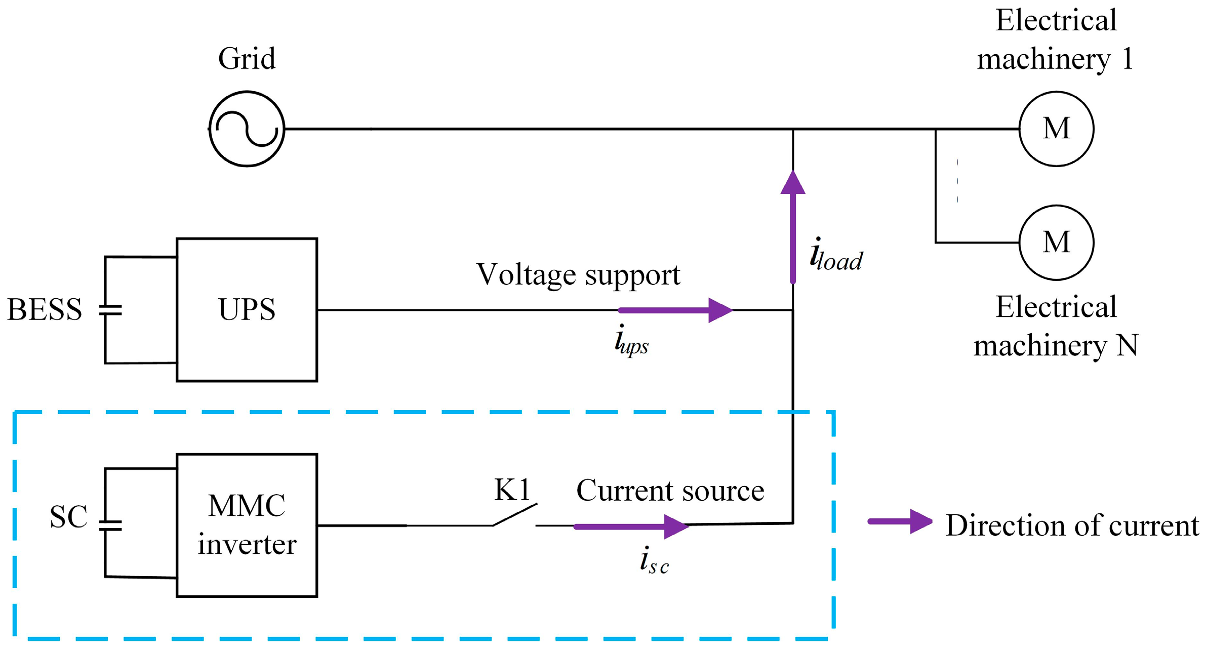
The integration scheme of the UPS and SC energy storage device often adopts the scheme of DC side access; in this scheme, in order to cope with the current shock at the initial stage of the black start, an increase in the UPS and SC capacity leads to an increase in the converter cost. In contrast, the AC side access scheme can effectively reduce the economic cost.
In summary, most existing power system black start schemes use a separate LAB as the black start power source, and most control strategies use energy storage as a voltage source to participate in black start coordination. However, this solution cannot guarantee the high reliability of black starts in complex power systems. Faced with large surge currents, it lacks the ability to limit the amplitude, and the low cycle and slow response of the LAB restrict the dynamic characteristics and economy of black starts. Meanwhile, the control parameters set based on experience cannot adapt to the complex and ever-changing power system, which may affect the stability and efficiency of the energy storage black start system. At present, there are few studies that use the SC as a current source to participate in power system black starts, and there is limited research on control strategies for the HESS based on the SC to participate in power system black starts.
Based on the above issues, a HESS black start control strategy for power systems based on the SC is proposed. The main contributions of this paper are summarized as follows:
  • Propose a HESS black start system structure with a direct parallel connection on the AC side. The LAB provides long-term rated power as the main power source, and the SC serves as a current source to provide an additional surge current in the initial stage, and the economy of HESS black start has been effectively improved.
  • Propose an adaptive control strategy based on the VSG and MPC. Adaptively adjust the control parameters based on frequency and angular velocity deviation; the goal is to minimize the error between the reference current and the output current, and, by controlling the output current, the response speed and robustness performance have been improved.
  • A generator power level identification model has been proposed. Based on the characteristics of the starting current, it is possible to achieve an accurate identification of the starting generator in the power system at the ms level, and the resource allocation of the hybrid energy storage black start system has been optimized.
  • Selecting generators of different power levels in the power system for black start testing, real data is compared and summarized, and the good control effect of the proposed black start control strategy in different typical scenarios has been proven.

2. Structure of HESS Black Start System

2.1. MMC of SC Energy Storage

In the traditional energy storage inverter structure, the voltage and switching frequency are lower, and it causes the inverter to lack capacity advantages, and it is difficult to be widely used in high-power scenarios. The MMC has a high degree of modularity and integration, and it can make up for the shortcomings of the traditional inverter structure, and effectively improve the reliability and flexibility of the black start system. The topology of the SC energy storage inverter using the MMC is shown in Figure 1.
The modular SC energy storage inverter includes three phases and six arms; each phase is divided into upper and lower arm, and n sub modules (SMs) are connected in series. Each phase can output an n + 1 electrical level, and the half bridge circuit is applied in the SM; the output voltage can be adjusted by controlling the power switch, and the operation mode is as follows:
(1)
Locking status: All electronic components are locked. Determine whether to cut off the SM according to the current flow direction. When the current is positive, the upper power tube is turned on, with the output voltage of the SM being uSM = uC. When the current is negative, uSM = 0.
(2)
Input status: S1 is turned on and S2 is turned off, and uSM = uC.
(3)
Cut status: S1 is turned off and S2 is turned on, and uSM = 0.
The equivalent circuit of the single-phase MMC is shown in Figure 2. u a is the voltage output by inverter, usa is the AC side grid voltage, and upa and una is the upper arm voltage and lower arm voltage of the SM, according to Kirchhoff’s law:
U d c 2 u a = u p a + L d i p a d t U d c 2 + u a = u n a + L d i n a d t u a = L s d i a d t + u s a
Because of i a = i p a + i n a , Equation (2) can be obtained as follows:
u n a u p a 2 = L s + L 2 d i a d t + u s a
Due to the single-phase circulating current i c _ a = i p a + i n a / 2 , the voltage of the DC side can be described as follows:
U d c = u p a + u n a + 2 L d i c _ a d t
From Equation (3), it can be found that the AC and DC sides of the SC inverter are independent of each other, and there is no coupling relationship. This structure can effectively reduce the electromagnetic interference, and improve the reliability of the system.

2.2. Black Start Control System of HESS

In order to solve the surge current of the generator, the SC and traditional UPS are combined to form the HESS black start device, and its structure is shown in Figure 3. The AC bus structure is adopted, and the inverter of the SC is directly connected with the AC side of the UPS, and the switching control of the SC is realized through the switch K1. The real-time current for the generator is i load . As a voltage source, the UPS provides long-term voltage support for the black start, and the output current is the rated current of the generator, i.e., i u o s = i load _ n . The inverter of the SC is used as the current source to support the impulse current, and the reference output current is i sc * = i l o a d i u p s .
In this structure, the black start can be divided into the following stages:
(1)
Manually start the UPS, and check the operation status of the UPS; the K1 is closed, the power conversion system (PCS) of the SC is started, and the PCS is in standby mode.
(2)
Detect the starting current of generator i load , judge the power level of the generator, and set the rated current i l o a d _ n and the reference current of the PCS. When i load i l o a d _ n , the current is independently supported by the UPS. When i load > i l o a d _ n , the K1 is closed, and the PCS of the SC is started quickly to support an additional impulse current.
(3)
After a period of stable operation of the generator, i load is gradually reduced. When i l o a d < i l o a d _ n , the output current of the PCS is 0, the K1 is opened, and the UPS provides power independently.
(4)
During the restart period, the K1 is opened, and the remaining capacity of the UPS is checked to determine if it can support the secondary startup of the generator. The K1 is closed, and the SC charging mode is activated. Monitor the charging current and voltage to complete balanced charging.
Since the UPS needs to continuously provide reliable power, in order to improve the stability and robustness of the system, the VSG is used to design the control system of the UPS. In order to ensure fast response characteristics and improve the stability of the PCS, the VSG and MPC are used to control the output current. The black start control system of the HESS is shown in Figure 4.
In this system, the three-phase voltage and current of the UPS and PCs are u u p s , a b c , i u p s , a b c , u s c , a b c , i s c , a b c , the voltage of the UPS u u p s , and the voltage of the PCS u s c , which can be obtained through the VSG. In the UPS control unit, the output voltage is controlled by the double closed loop. It is worth noting that the output current of the UPS needs to be limited through the current limit link, i.e., i u p s * i l o a d , n . In the control system of the PCS, the reference current of PCS i sc * needs to be calculated, i sc * = i l o a d i u p s . The voltage and current output by the PCS are input into the prediction model to obtain the current prediction value at the next time. Using the objection function, the current can be adjusted in real time according to the predicted value and i sc * . The corresponding switch signal is obtained to control the SC, and the fast constant current control of the PCS can be achieved.

3. Adaptive VSG Control Strategy

3.1. Principle of VSG Control

The control structure of the VSG is the same as the traditional control strategy, and it is mainly composed of the power loop, voltage loop, and current loop. The active power loop of the VSG is composed of the governor and rotor operation equation. When the active power is changed, the system frequency can be changed proportionally through the governor. The governor is expressed as follows:
m × ω ω n = P P ref
m is the active frequency droop coefficient of the VSG, ω is the output angular frequency, and P is the active power, respectively. ω n is the rated angular frequency, and Pref is the rated active power.
The rotor motion equation of the VSG can provide damping inertia support, the frequency–power changes more smoothly, and the dynamic stability of the system can be improved. The mechanical motion equation of VSG can be expressed as follows:
J d ω d t = T m T e D ω ω n d δ d t = ω ω n
In Equation (3), J is the moment of inertia, D is damping coefficient, Tm is mechanical torque, Te is electromagnetic torque, and δ is power angle. Te can be expressed as follows:
T e = P e ω = u a i a + u b i b + u c i c ω
Ia,b,c is the output current, and Ua,b,c is the electric potential. Pe is the average electromagnetic power of the VSG obtained by the notch filter; its specific calculation method is as follows:
P = 3 2 U o d I o d + U o q I o q Q = 3 2 U o d I o q + U o q I o d P e = s 2 + ω m 2 s 2 + 2 ζ ω m s + ω m 2 P
Since the mechanical power Pm of the VSG has the following relationship with the rated output power Pref,
P m = P r e f + Δ P
Combining Equations (5)–(8), according to the angular frequency variation Δ ω = ω ω 0 , the mechanical equation can be obtained:
J d Δ ω d t = P ref ω n P e ω ( m ω n + D ) Δ ω
For the reactive power loop in the VSG, by utilizing the primary voltage regulation characteristic of the VSG, the response speed and regulation accuracy of the system can be improved, and the specific expression is as follows:
u n = u 0 + n ( Q r e f Q ) + k v ( u n u 0 ) ]
u0 and un are the output voltage and rated voltage, respectively, Qref is the rated reactive power, Q is the reactive power of energy storage, n is the reactive droop coefficient, and kv is the reactive voltage coefficient.
According to Equations (9) and (10), the VSG control system of energy storage can be obtained, and the structure of the control system is shown in Figure 5.

3.2. Small Signal Model Analysis of VSG

To clarify the impact of J, D, and line impedance on the stability of the HESS system, the small signal model based on the VSG is modeled and analyzed. The three-phase AC voltage of the HESS is U H E S S , and the voltage of the grid-connected power is U. Because the phase angle deviation between the HESS and the voltage of power system is very small, sin δ δ , cos δ 1 , and the line inductance and resistance of the system are X and R, respectively. When the total active power and active power output by the HESS are P H E S S and Q H E S S , the apparent power output by the HESS can be calculated as follows:
S = P H E S S + j Q H E S S = R U U H E S S R U H E S S 2 + X U U H E S S δ R 2 + X 2 + j X U U H E S S + X U H E S S 2 + R U U H E S S δ R 2 + X 2
At this time, the small signal model of the HESS output active power and reactive power can be established as follows:
Δ P H E S S = Δ δ P H E S S δ + Δ U P H E S S δ = Δ δ R U U H E S S δ + X U U H E S S R 2 + X 2 + Δ U R U H E S S + X U H E S S R 2 + X 2 Δ Q H E S S = Δ δ Q H E S S δ + Δ U H E S S P H E S S U H E S S = Δ δ X U U H E S S δ + R U U H E S S R 2 + X 2 + Δ U H E S S X U + R U δ R 2 + X 2
When the HESS is connected to the power system, the angular velocity of the VSG control system meets ω = ω n , and the small signal model can be obtained as follows:
Δ P H E S S = s J ω n s + D ω n Δ δ Δ Q H E S S = s 1 + T a Δ U H E S S k 1 s + k 2
Ta is the delay constant, k1 is the sum of the reactive voltage coefficient and reactive proportional coefficient, and K2 is the reactive integration coefficient.
According to the above equation, when the HESS system is stable, the small signal model can be established as follows:
Δ δ ¨ Δ U ¨ H E S S Δ δ ˙ Δ U ˙ H E S S = D J 0 P H E S S J ω n δ P H E S S J U H E S S k 1 Q H E S S δ k 1 Q H E S S U H E S S k 2 Q H E S S δ k 2 Q H E S S U H E S S 1 0 0 0 0 1 0 0 Δ δ ˙ Δ U ˙ H E S S Δ δ Δ U H E S S
According to the analysis, the root locus curves of J and D are drawn as the following figure, respectively.
According to Figure 6 and Figure 7, it can be found that, when D is fixed, with the increase in J, the control system transits from an overdamped state to an underdamped state, the overshoot is gradually increased, and the system is gradually divergent. When J is fixed, with the increase in D, the system transits from an underdamped state to an overdamped state, and the system gradually recovers from an unstable state to a stable state again. However, when D is too large, the response speed of the system will be reduced, affecting the dynamic performance, and the fast response of the HESS black start cannot be achieved.
According to the VSG principle, when the small signal disturbances occur, the P-f equation of the VSG can be written as follows:
Δ ω = 1 J ω 0 s + D ω 0 + 1 m Δ P H E S S s Δ φ = Δ ω
Without simplifying the power angle, for a line impedance Z = R + jX, the current flowing into the PCC from the VSG is follows:
I ˙ = R U H E S S cos δ R U + X U H E S S sin δ R 2 + X 2 + j R U H E S S sin δ + X U X U H E S S cos δ R 2 + X 2
At this point, considering the line impedance and power angle, the apparent power S can be expressed as follows:
S = R U H E S S U cos δ R U 2 + X U U H E S S sin δ R 2 + X 2 + j R U H E S S U sin δ + X U 2 X U U H E S S cos δ R 2 + X 2
The small signal model of the active and reactive power output by the VSG can be represented as follows:
Δ P H E S S = R U H E S S U sin δ + X U U H E S S cos δ R 2 + X 2 Δ δ + R U cos δ + X U sin δ R 2 + X 2 Δ U H E S S Δ Q H E S S = R U H E S S U cos δ + X U U H E S S sin δ R 2 + X 2 Δ δ + R U sin δ X U cos δ R 2 + X 2 Δ U H E S S
Because Δ ω H E S S = ω H E S S ω 0 , we can obtain the following:
J s = Δ P H E S S ω 0 D Δ ω H E S S
Bring ω H E S S = δ , ω H E S S = s δ into Equation (19):
s J s + D Δ δ = Δ P H E S S ω 0
By deforming the Q-U droop equation, we can obtain the following:
Δ U H E S S = K Δ Q H E S S
Combining Equation (18) with Equation (21), the small signal model of the energy storage VSG inverter under disturbance is obtained as follows:
Δ δ ¨ Δ δ ˙ Δ U H E S S = D J P H E S S δ 1 J ω P H E S S U H E S S 1 J ω 1 0 0 K Q H E S S δ 1 + K 0 0 Δ δ ˙ Δ δ Δ U H E S S
The characteristic root trajectories under different line impedance scenarios are shown in Figure 8.

3.3. Adaptive Adjustment of Parameters

According to the analysis in Section 3.2, setting a reasonable J and D can ensure the operation stability of the HESS, and realize the rapid tracking response for the current. According to a stability analysis, the basic selection principles of J and D can be obtained and it is shown in Table 1.
Because J is related to the angular velocity variation and rate of change, J can be adaptively adjusted by introducing the relevant adjustment coefficients as follows:
J = J o ,   Δ ω α J 0 + K J Δ ω Δ ω d ω d t , ( Δ ω > α ) ( Δ ω d ω d t 0 ) J 0 K J Δ ω Δ ω d ω d t , ( Δ ω > α ) ( Δ ω d ω d t < 0 ) K J = | ε ln ( Δ ω α ) |
J 0 is the virtual inertia of the HESS under stable conditions, KJ and ε are parameters for adaptation, K J = J J 0 Δ ω , the set angular frequency deviation threshold is α , and its value determines the frequency of changes in J and D; if the value is too small, it is easy to make the parameters change frequently, which is not conducive to the stability of the system. If the value is too large, the frequency change rate and frequency deviation cannot be effectively suppressed. Therefore, based on the deviation of the output power and angular frequency, the range of α can be constrained. The specific value method is as follows [22]:
α = P n 10 P P n Δ ω
(1)
When Δ ω | α , this indicates that the angular velocity deviation is within the allowable range of the system; at this time, the value of J is still the virtual inertia J0 during stable operation.
(2)
When Δ ω | > α and Δ ω d ω d t 0 , the angular velocity deviation of the system is too large; according to Table 1, it is necessary to increase the moment of inertia. By introducing the adjustment coefficient KJ, the change in angular velocity can be combined with the change rate, and J can be adjusted adaptively according to the specific change trend in angular velocity.
(3)
When Δ ω | > α and Δ ω d ω d t < 0 , the angular velocity deviation of the system is too large; according to Table 1, if the system recovers to stability, the moment of inertia needs to be reduced, and the principle of the adaptive parameter adjustment is the same as (2).
Since D is only related to the change in angular velocity, and the value range of D is larger, if D is adaptively adjusted using the same principle, the change rate of parameters may increase, and it will do harm to the system. Therefore, the traditional linear method can be selected, and the specific adaptive calculation model is expressed as follows:
D = D o ,   Δ ω α J 0 + K D | Δ ω | ,   Δ ω > α
D0 is the stable damping coefficient of the HESS, and KD is the regulating parameter.

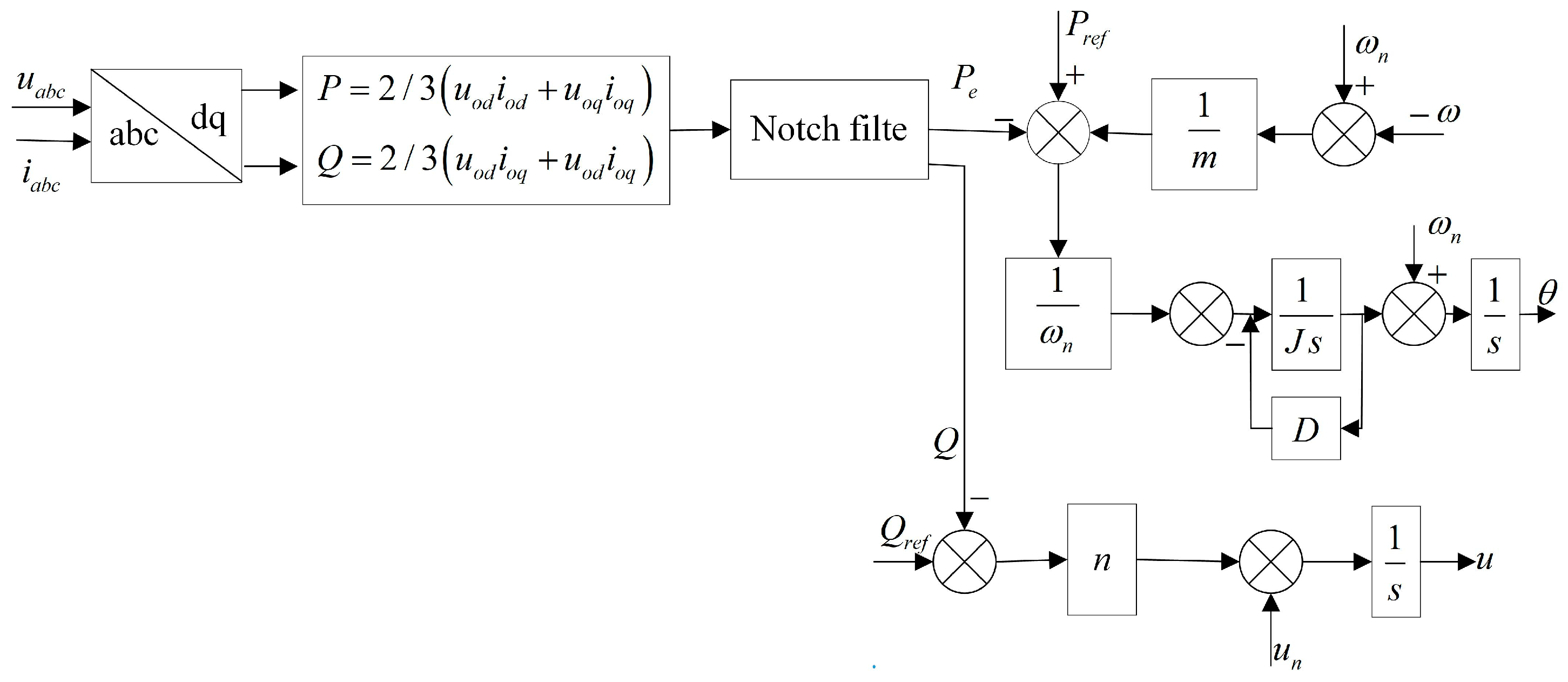
4. MPC-VSG Adaptive Fast Response Control

The PCS can improve the reliability of black starts in power systems by responding quickly to the current. The double closed loop with a PI controller is often used in traditional VSG control systems. However, when the generator or the HESS has an external disturbance, it is difficult to adjust the output currents quickly, and this results in a longer dynamic response. The MPC can effectively predict system states and achieve fast current tracking through the real-time optimization of control inputs. When the adaptive VSG is combined with the MPC, it can significantly improve the system robustness and dynamic performance.
As shown in Figure 9, the MPC can establish a discrete prediction model to predict controlled variables such as the power, voltage, and current. The state deviation between the actual output and the predicted state is used to correct the target model.
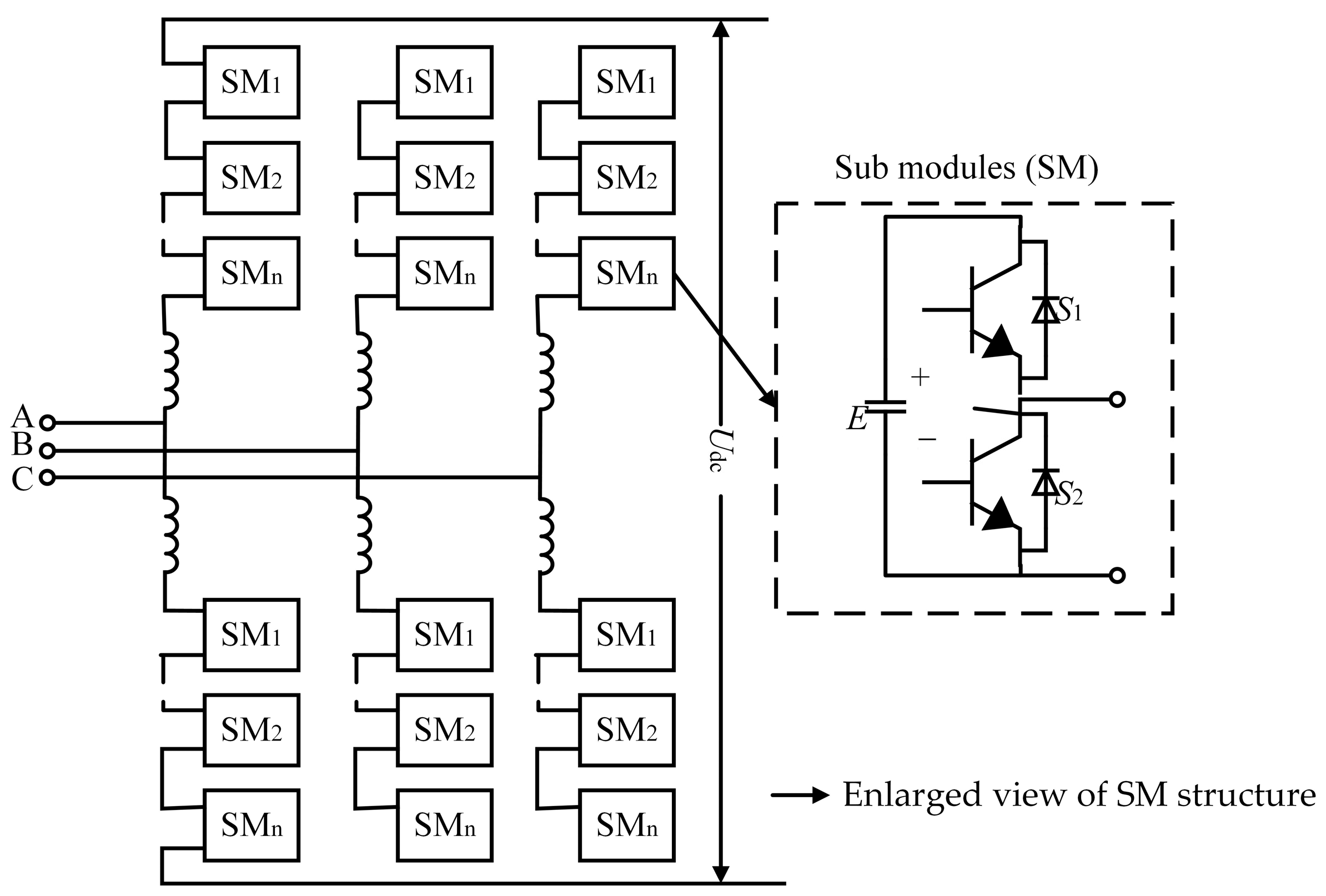
According to the analysis of the MMC inverter, the switch status signal S of the SM can be defined as follows:
S x y i = 0 ,   cut 1 ,     input
In Equation (26), x = u or p, and this indicates the upper and lower arm of the single-phase inverter. y = a, b, c, and this indicates the phase of the inverter. i [ 1 , n ] is the index of the submodule of the inverter single arm.
The three-phase voltage of the system can be expressed as follows:
v x a = i = 1 n S x a i v c m v x b = i = 1 n S x b i v c m v x c = i = 1 n S x c i v c m
vcm represents the capacitance voltage of each SM.
Assuming that the equivalent resistance of each arm is R, the equivalent inductance is L. The upper and lower arm currents are iuy, and iny, and the upper and lower arm voltage are vuy, and vny. The phase current is iy. The phase voltage can be obtained as follows:
v y = v n y v u y L d i y d t + R i y 2 = ( V d c 2 v y L d i u y d t R i u y ) ( V d c 2 + v y L d i n y d t R i n y ) L d i y d t + R i y 2
i y = i u y i n y , and the output voltage of inverter is as follows:
v = 2 v x y = a + 1 2 + j 3 2 v x y = b + 1 2 j 3 2 v x y = c 3
Therefore, the output voltage of the PCS can be controlled by the switch variable Sxyi.
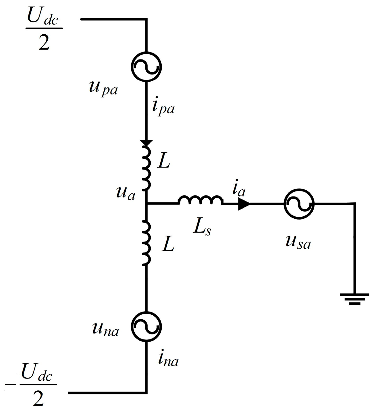
vyN is taken as the three-phase voltage on the power grid, and the dynamic equation of the three-phase current is constructed as follows:
v y N = L d i y d t + R i y + e y + v n N e y = v n y v u y 2
because of
i = 2 3 i y = a + 1 2 + j 3 2 i y = b + 1 2 j 3 2 i y = c e = 2 3 e y = a + 1 2 + j 3 2 e y = b + 1 2 j 3 2 e y = c
According to Equation (29) to Equation (31), we can obtain the following: v = R i + L d i d t + e . The forward phase difference method is used to discretize the differentiation of the current, and Ts is the sampling period.
d i d t = i k + 1 i k T s
The predicted current value i k + 1 of the PCS at the (k + 1) moment can be obtained at the k moment:
i k + 1 = ( L + R T s ) i k + T s v k e k L
The current prediction values obtained from Equation (31) are transformed via park transformation to derive i α k + 1 and i β k + 1 . According to the principle of the HESS, during the black start, the PCS needs to calculate the reference current through the reference module, and the reference current i s c * k is formulated as follows:
i s c * k = i l o a d k i u p s k
Similarly, i s c * is transformed to i s c , α * and i s c , β * . To achieve the fast current tracking of the HESS, the objection function of the MPC is formulated as follows:
F = i s c , α * k + 1 i α k + 1 + i s c , β * k + 1 i β k + 1
Based on Equations (31) and (33), the collected output voltage and current are fed into the prediction model to forecast i’(k + 1). Combined with the output current of the adaptive VSG, these predicted values are incorporated into the objection function. Minimizing the F is taken as the goal, and the optimal switching sequence Sxyi is generated through multiple optimization iterations. This sequence is then actuated through the PCS to finish the rapid current response during the black start.

5. Generator Black Start Power Identification Strategy

After the power system is completely paralyzed, it is necessary to reconstruct the power supply path through a self-consistent approach. However, as the main power source during the black start process of the power system, if the start-up electric energy is directly provided to its power plant, the energy storage black start device requires a large capacity configuration, and the feasibility and economy of this method are relatively low. In the initial stage of the black start in the power system, the generator is used as an auxiliary power source to supply power for important loads; at the same time, it can provide the initial start-up electric energy to the main power supply, and the power supply path is gradually being restored. Therefore, the black start of generator is the core of rebuilding the power supply network of the power system. At present, the types of generators are diversified. The different power level of the generator has different requirements for the power supply. The power level of the generator can be accurately and quickly identified through a characteristic analysis of the generator startup currents, and the resource matching efficiency and reliability of the black start can be significantly enhanced.
The starting current is affected by the instantaneous inductance, and it exhibits typical transient characteristics. The sampling interval is Ts, and the sampled generator startup current can be expressed as follows:
I l o a d [ n ] = I n T s
During the black start phase, different generators have different peak currents. By capturing the maximum value of the current, a preliminary judgment can be made on the power level of the generator. The peak current is defined as follows:
I peak = max I l o a d n
The power level of the generator determines the time required for the starting current to rise to its peak value. The inductance and inertia of high-power generators are relatively large, which leads to a longer rise time of the current. trise is defined as the duration required for the current to increase from 10% to 90% of its peak value, and it can be expressed as follows:
t r i s e = n 1 T s n 2 T s
n1 and n2 are the sampling values corresponding to 90% and 10% of the Ipeak, respectively.
The current rise rate of the high-power generator is small, and it can be expressed by the rate of the current change before the peak value.
d I r i s e d t = I n p e a k T s I n s t a r t T s ( n p e a k n s t a r t ) T s
npeak is the sampling point that reaches the peak value, and nstart is the sampling point where the current starts to rise. The attenuation rate is related to the generator power level. The higher the power, the slower decay rate of the generator. Let nfall denote the sampling point when the current decays to a specified threshold, and the startup current decay rate model is as follows:
d I f a l l d t = I n fall T s I n p e a k T s ( n f a l l n peak ) T s
The time constant can also describe the attenuation characteristics of the current, and high-power generators have large transient time constants.
I l o a d n T s = I p e a k e n T s τ
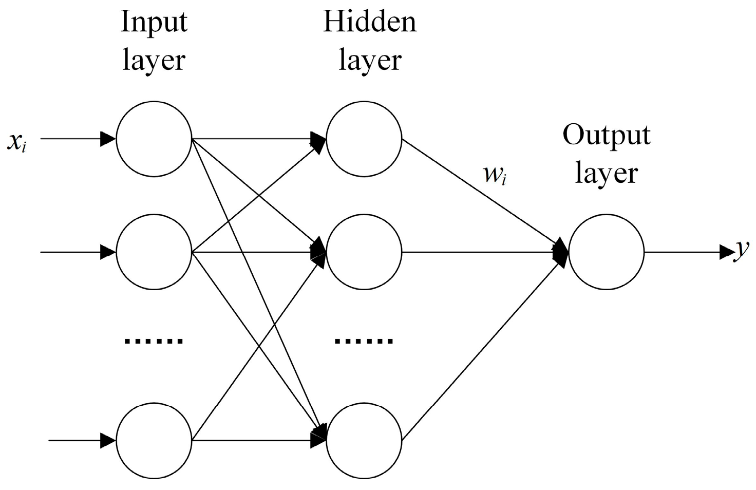
The radial basis function (RBF) neural network is a feedforward neural network. Compared with other feedforward neural networks, the RBF has better approximation performance and global optimality. Because of its simple network structure, it has a faster convergence speed and it can meet the requirements of generator power recognition at the ms level.
The structure of the RBF neural network is shown in Figure 10. It consists of three layers of network structure: the input layer, hidden layer, and output layer. The input layer receives the feature vector x, and each input node corresponds to a specific input feature. The hidden layer consists of multiple RBF nodes, each applying a radial basis function to nonlinearly transform the input features. The common radial basis function is the Gaussian function, and it can be expressed in the following form.
h j ( x ) = exp x c j 2 2 σ j 2
c j represents the center of the j-th node, and σ j is the variance of the Gaussian function. The input node vector x can be linearly weighted to obtain y. When the linear weight of the output layer is w j , the RBF output model is expressed as follows:
y ( x ) = j = 1 M w j h j ( x )
A power-level identification feature database is established based on Equation (36) to Equation (41). For a system which contains M kinds of generators, the input feature vector for each generator is F m = I p e a k , m , t r i s e , m , d I r i s e , m d t ,   d I f a l l , m d t , τ m .To accurately model the complex nonlinear characteristics of the startup current, an ensemble RBF (ERBF) algorithm is employed for data-driven modeling. By injecting noise, multiple RBF models are generated and their outputs are integrated to enhance the model robustness and generalization capability.
Gaussian white noise ϵ k is added to the input features x, and multiple different noisy datasets x k can be obtained. x k is utilized to train RBF networks, so that the adaptability of the model is enhanced. The mathematical representation of this process is formulated as follows:
x k = x + ϵ k , ϵ k ~ N ( 0 , σ 2 )
Each network learns different characteristics of the current, and the corresponding prediction results can be output. The output of an individual RBF network during this process is denoted as follows:
I k ( t ) = j = 1 M w j , k exp x k c j , k 2 2 σ j , k 2
The weighted average current model is expressed as follows:
I ERBF ( t ) = k = 1 P α k I k ( t )
P denotes the number of RBF networks generated via noise injection. α k represents the weighting coefficient for each RBF network, subject to k = 1 N α k = 1 .
The feature vector F m is fed into the ERBF model. According to Equation (45), we can calculate the distance between the characteristic vector of the tested generator and the vectors in the database. The index m corresponding to the minimum distance identifies the power rating.
Distance ( m ) = k = 1 5 ( F test , k F m , k ) 2

6. Experiment Results

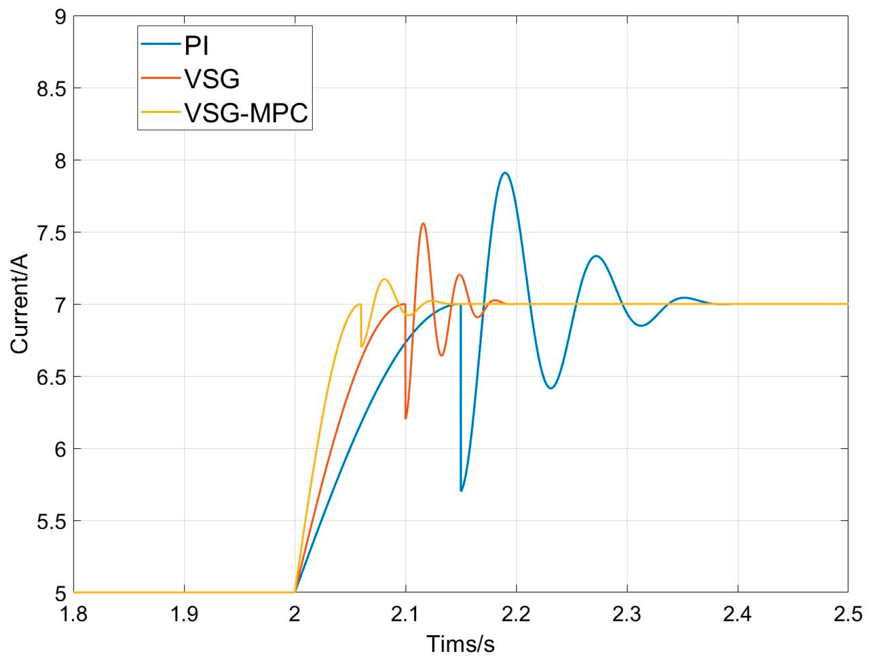
To verify the superiority of the method proposed in this article, a small simulation model was built on the MATLAB (R2018a) simulation platform. When t = 2 s, the reference current of the HESS increases from 5 A to 7 A, traditional PI control, the VSG, and the VSG/MPC are, respectively, used to track and control the current, and the current waveforms output by the three control methods are shown in Figure 11.
It can be clearly seen that traditional PI control is affected by the lag in the integration process, and the response speed to the reference current is the slowest; at the same time, the current is accompanied by significant fluctuations, and the maximum current error have reached 0.8 A. Under the influence of the VSG control strategy, the current can reach the reference current value within 0.18 s. Compared with the PI control, its current fluctuation is lower. The control strategy proposed in this article has the fastest response speed, and it can achieve current tracking control within 0.15 s, and the maximum current deviation is only 0.25 A.
Taking the 160 kW demand scenario as an example, the LAB and SC are used separately to provide the black start power. According to Table 2, it can be seen that, if the LAB with a 0.2c charge rate is used to support the starting current of a 160 kW generator, the required capacity for the configuration is 800 kWh. If the SC with a 5c charge rate is used to support the starting current of a 160 kW generator, the required capacity for the configuration is 36 kWh. Although the unit price of the SC is much higher than that of the LAB, the SC only requires a very small capacity to meet the same surge current, and the total cost of ownership (TCO) under this scheme is reduced by 79% compared to the traditional scheme. The proposed plan effectively reduces the energy waste rate and has better economic viability.
Based on the proposed control strategy and system architecture, a hardware circuit platform is established. In the test case, the rated power of the PCS is 800 kW, and the rated power of the UPS is 400 kW. There are a total of three generators ready for the black start. The power of the generators is 160 kW, 75 kW, and 7.5 kW, respectively.
Figure 12 shows generator current Iload, and compensation current Isc of the PCS and voltage of the UPS during the 75 kW generator black start. The rated current of the 75 kW generator is 150 A; once the starting current exceeds the rated value, the PCS activates the rapid reference current tracking control. It is worth mentioning that, due to the proposed algorithm not compensating for harmonics, there is distortion in the output current. According to 
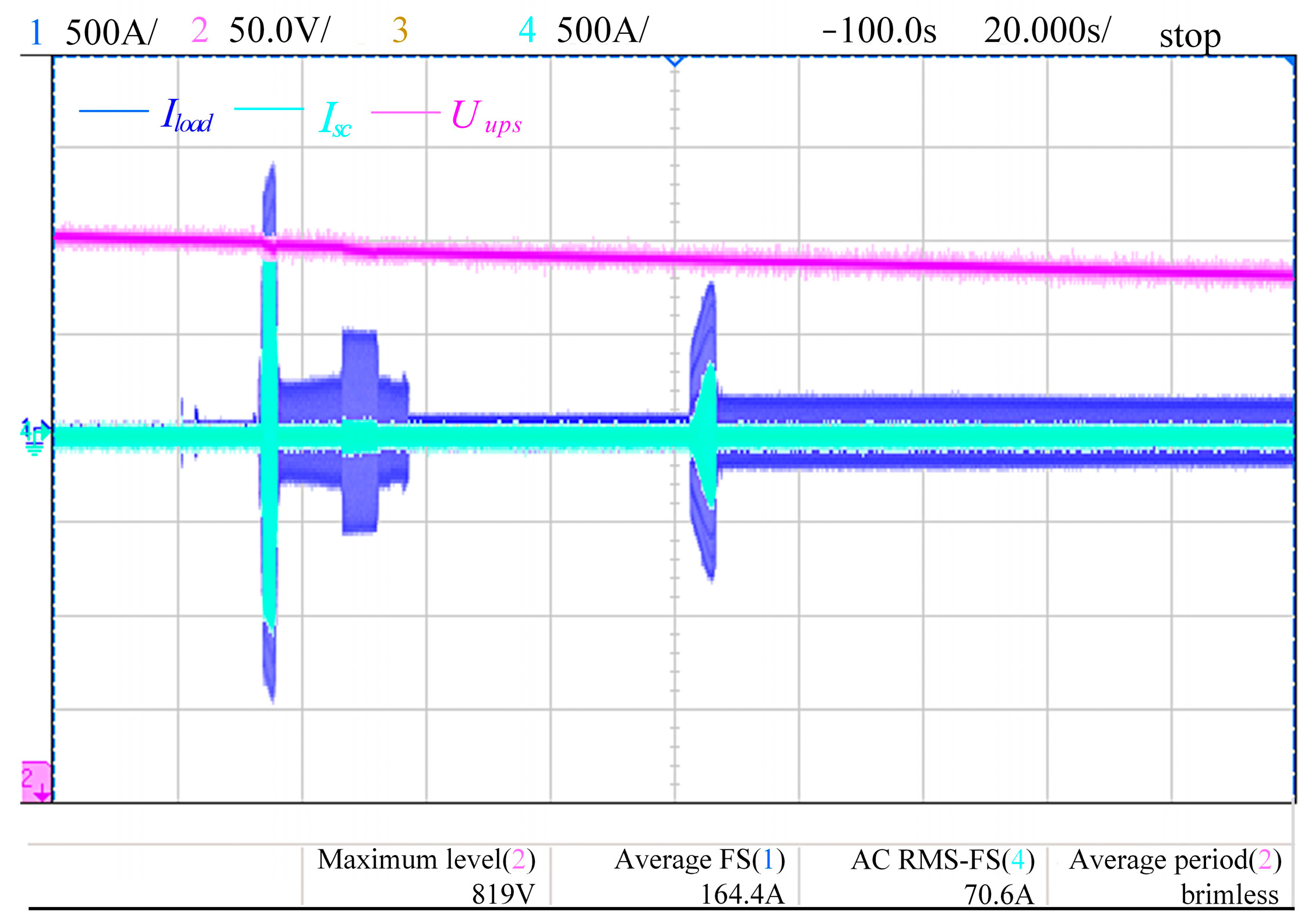
Figure 12b, the maximum starting current reaches 507.5 A, and the transient peak nearly reaches 800 A. At the same time, the compensation current output by the PCS is 354.9 A. In Figure 12c, upon completion of the 75 kW generator startup, the PCS quickly stops outputting the compensation current, and the black start of the power system is completely taken over by the UPS.
The voltage and current waveforms during the black start of the 160 kW generator are shown in Figure 13. The trigger value for the PCS output compensation current is set to 150 A. The envelope diagram of load current Iload, UPS voltage Uups, and PCS compensation current Isc is shown in Figure 13a. The experimental result that is shown in Figure 13b indicates that the maximum RMS of the current reaches 921 A, and the compensation current output by the PCS reaches 816 A. This indicates that the proposed control strategy has fast and accurate compensation following characteristics. According to Figure 13c, when the starting current returns to the rated value, it indicates that the 160 kW generator has completed starting. At this point, the compensation current of the PCS decays to 0 A, and the UPS continues to output electrical energy to support the normal operation of the generator.
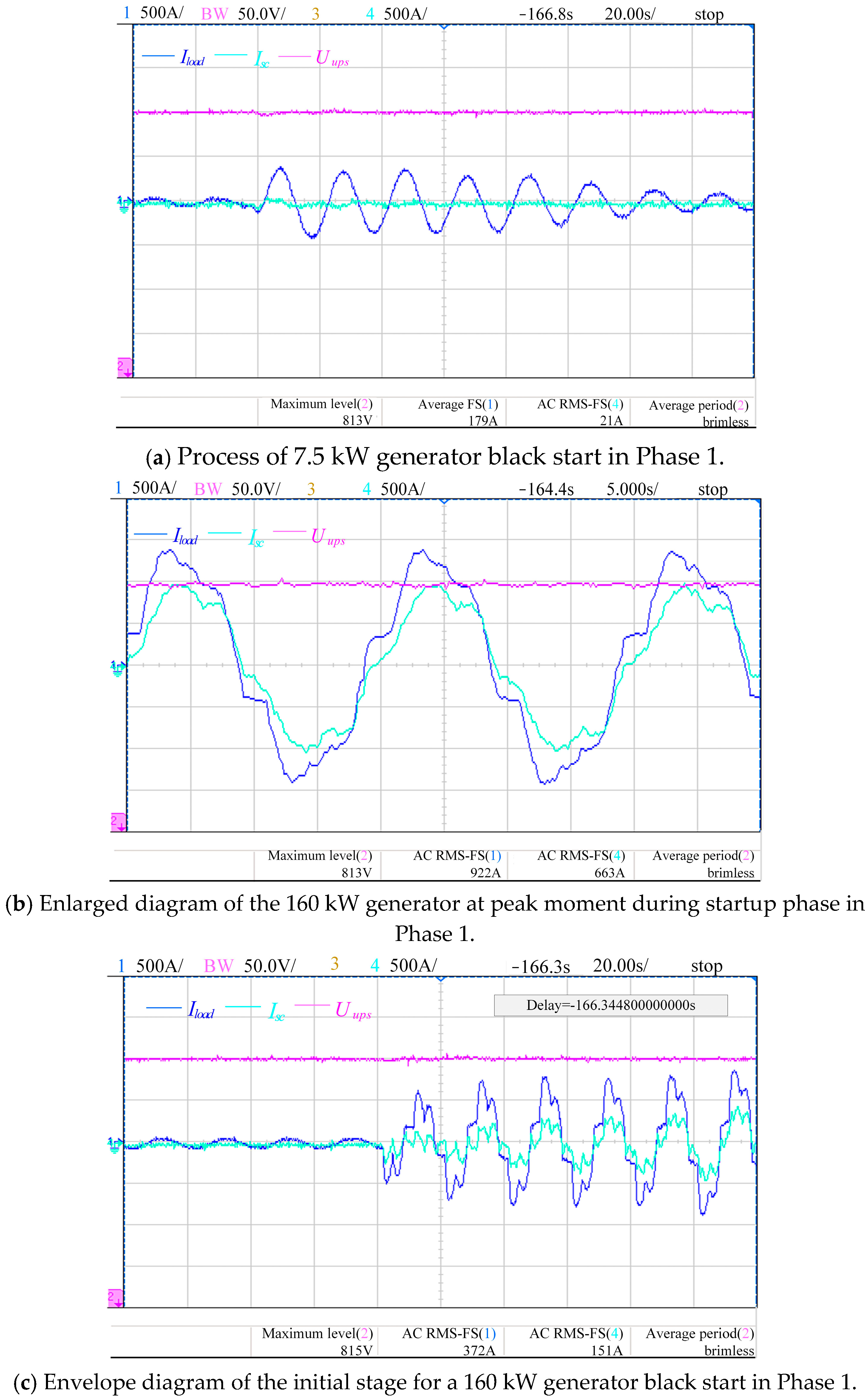
The combined black start process of the 7.5 kW, 160 kW, and 75 kW generators is shown in Figure 14. The compensation current trigger threshold of the PCS is set to 270 A. In this experiment, the startup sequence is divided into two phases. In Phase 1, the 7.5 kW and 160 kW generators are continuously started. After the 7.5 kW generator is started, the 160 kW generator is immediately started. After a period of stable operation, Phase 2 begins to achieve the black start of the 75 kW generator.
As is shown in Figure 15a, the maximum RMS of the 7.5 kW generator current is approximately 250 A, and it is still below the PCS compensation threshold. The UPS can provide stable electrical energy for the generator independently. After the 7.5 kW generator is started, the maximum current and initial current of the 160 kW generator is shown in Figure 15b and Figure 15c, respectively. The peak RMS current during startup measures 922 A, which exceeds the 270 A threshold. The compensation current output by PCS is 663 A, and this value is almost consistent with the UPS load target value set by the system. The experimental results in Figure 15c indicates that the initial current of the generator has exceeded the set value; at this time, the PCS begins to cooperate with the UPS, and it can closely follow the trend of the starting current to track and control the compensation current.
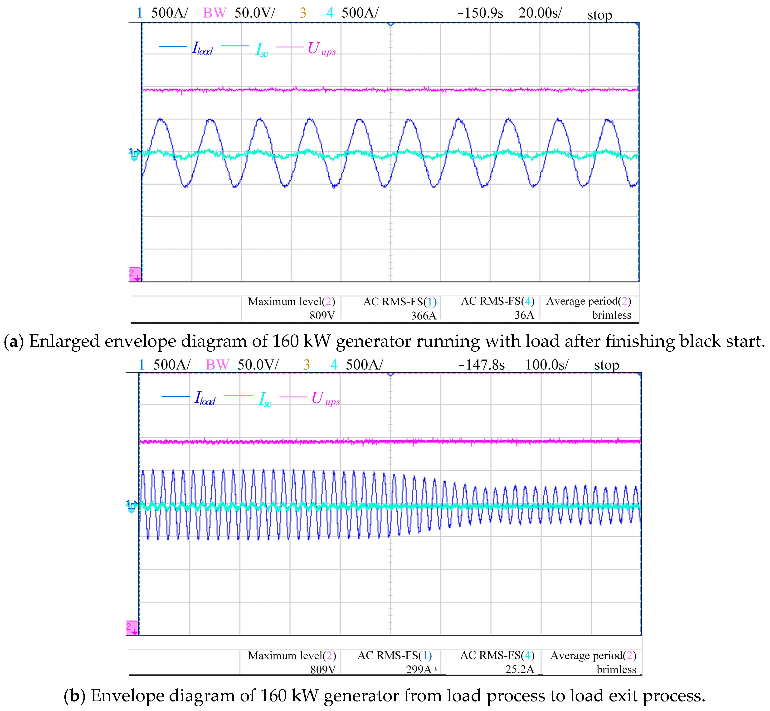
In Phase 1, after the 160 kW generator is started, the load is connected to verify the effectiveness of the black start strategy. Figure 16a and Figure 16b show the black start curves of the 160 kW generator with load and without load, respectively. According to the experimental results, it can be found that the current of the generator with load is 366 A, and it has exceeded the limit value. At this time, the compensation current of the PCS is 36 A. Because the current is small, there is a certain amount of error. After the load is removed, the current output by the PCS decreases as the generator current decreases. According to the experimental results, it can be found that the control strategy proposed can ensure the fast current response of the HESS black start and achieve the smooth output of the HESS.
In Phase 2, the 75 kW generator is ready to start. As shown in Figure 17, the total starting time for the 75 kW generator is 5 s, and the maximum starting current reaches 750 A. As the starting current decreases, the current output by the PCS also gradually decreases. When the compensation current decreases to 0 A, it indicates that the generator has completed starting.
The analysis of Figure 12, Figure 13, Figure 14, Figure 15, Figure 16 and Figure 17 demonstrates that the HESS black start system, guided by the proposed generator power-level identification strategy, achieves rapid and accurate generator recognition based on the starting current signatures, thereby enabling the robust multi-stage coordinated control for generator black starts.

7. Conclusions

To address the limitations of low reliability and a poor dynamic response in existing black start solutions, a structure of the HESS black start device based on the SC is proposed. The SC inverter constructed with an MMC structure can be directly connected to the AC side of the UPS, significantly reducing the configuration costs of the black start device. By implementing the SM switching control, the system can enhance the operational flexibility and adaptability in black start scenarios. For the SC inverter, an adaptive control strategy combining the MPC and VSG is developed. This strategy adaptively adjusts the control parameters based on system-state deviations while enabling the rapid tracking of reference currents through MPC optimization, which improves the robustness and response characteristics of the HESS during black start operations. In order to further improve the reliability of the black start process, a generator power-level identification framework is established based on the proposed starting current model. The experimental results demonstrate that the strategy proposed in this article can accurately identify the generator within milliseconds. It can quickly track the starting current, and the dynamic response characteristics and reliability of the HESS black start have been effectively improved.

Author Contributions

Conceptualization, D.Y.; Methodology, Y.Z. (Yihua Zhang) and J.Y.; Software, Y.Z. (Yiyuan Zhang); Formal analysis, T.X.; Resources, Y.Z. (Yihua Zhang); Data curation, Z.C.; Visualization, X.H.; Supervision, T.X.; Project administration, X.H.; Funding acquisition, Z.C. All authors have read and agreed to the published version of the manuscript.

Funding

This work was supported by the Luquan Wudongde Power Plant of Three Gorges Jinsha River Yunchuan Hydropower Development Co, Ltd. (project number: 5224020028, and contract number: Z522402015).

Data Availability Statement

The original contributions presented in this study are included in the article. Further inquiries can be directed to the corresponding author.

Conflicts of Interest

Author Zhezhi Chen was employed by the company China Yangtze Power Co., Ltd. The remaining authors declare that the research was conducted in the absence of any commercial or financial relationships that could be construed as a potential conflict of interest. The authors declare that this study received funding from Luquan Wudongde Power Plant of Three Gorges Jinsha River Yunchuan Hydropower Development Co., Ltd. The funder was not involved in the study design, collection, analysis, interpretation of data, the writing of this article or the decision to submit it for publication.

References

  1. Zhang, Z.G.; Kang, C.Q. Challenges and Prospects for Constructing the New-type Power System Towards a Carbon Neutrality Future. Proc. CSEE 2022, 48, 2806–2819. [Google Scholar]
  2. Sun, R.; Liu, Y.; Wang, L. An online generator start-up algorithm for transmission system self-healing based on MCTS and sparse autoencoder. IEEE Trans. Power Syst. 2019, 34, 2061–2070. [Google Scholar] [CrossRef]
  3. Gan, W.; Ai, X.; Fang, J.; Yan, M.; Yao, W.; Zuo, W.; Wen, J. Security constrained co-planning of transmission expansion and energy storage. Appl. Energy 2019, 239, 383–394. [Google Scholar] [CrossRef]
  4. Xie, N.; Yang, P.H.; He, P. Research on Energy Storage Control Strategy During Whole Black Start Process of Wind-PV-Energy Storage Microgrid and Thermal Power Unit. Proc. CSU-EPSA 2023, 35, 75–82. [Google Scholar]
  5. Zhong, M.P.; Nick, J.; Jian, Z.W. Black Start from Renewable Energy Resources: Review and a Case Study of Great Britaint. Renew. Sustain. Energy Rev. 2025, 209, 115143. [Google Scholar]
  6. Li, J.; You, H.; Qi, J. Stratified Optimization Strategy Used for Restoration with Photovoltaic-Battery Energy Storage Systems as Black-Start Resources. IEEE Access 2019, 7, 127339–127352. [Google Scholar] [CrossRef]
  7. Li, C.Y.; Zhang, C.; Li, Z. Power Distribution Control Strategy of Energy Storage System in Black Start Process. Electr. Drive 2022, 52, 31–37. [Google Scholar]
  8. Li, X.J. Application of Collaborative Control Strategies for Grid Following Energy Storage and Grid Building Energy Storage in Power Systems. Autom. Appl. 2024, 65, 75–77. [Google Scholar]
  9. Huhn, E.; Braxtan, N.; Chen, S.-E.; Bombik, A.; Zhao, T.; Ma, L.; Sherman, J.; Roghani, S. Lithium-Ion Battery Thermal Runaway Suppression Using Water Spray Cooling. Energies 2025, 18, 2709. [Google Scholar] [CrossRef]
  10. Khan, H.A.; Tawalbeh, M.; Aljawrneh, B.; Abuwatfa, W.; Al-Othman, A.; Sadeghifar, H.; Olabi, A.G. A comprehensive review on supercapacitors: Their promise to flexibility, high temperature, materials, design, and challenges. Energy 2024, 295, 131043. [Google Scholar] [CrossRef]
  11. Israr, A.; Muhammad, S.; Kiran, K.; Muhammad, Z.; Javed, A.K.; Awais, Q.; Mohammad, I.; Ihsan, U.; Sana, U.; Anis, U.R.; et al. Double carbon matrix rGO and resorcinol formaldehyde aerogel supported mesoporous K-⸹MnO2 nano-spheres as anode material for high efficacy hybrid aqueous asymmetric super capacitor. J. Energy Storage 2025, 114, 115831. [Google Scholar]
  12. Jin, X.; Jiang, Z.; Feng, Y.; Fang, X. Optimization of cobalt-based MOFs for Super-capacitor Electrode Materials of New Energy Vehicle. Heliyon 2024, 10, 31222. [Google Scholar] [CrossRef] [PubMed]
  13. Tariq, M.; Ahmad, S.; Shahab, M.; Ahmad, I.; EL-Sherbeeny, A.M.; Abukhadra, M.R.; Rahman, A.U.; Ibrahim, M.; Ali, A.; Ni, H. Hierarchically porous Nb-δMnO2@CC as anode material for exceptional high performance aqueous asymmetric hybrid super capacitor. J. Energy Storage 2025, 119, 116432. [Google Scholar] [CrossRef]
  14. Gautam, M.; Patodia, T.; Gupta, V.; Sachdev, K.; Kushwaha, H.S. Synthesis of high surface area activated carbon from banana peels biomass for zinc-ion hybrid super-capacitor. J. Energy Storage 2024, 102, 114088. [Google Scholar] [CrossRef]
  15. Khalid, M.A. Review on the Selected Applications of Battery-Supercapacitor Hybrid Energy Storage Systems for Microgrids. Energies 2019, 12, 4559. [Google Scholar] [CrossRef]
  16. Huang, Y.H.; Kong, W.J.; Mei, T.; Li, J.; Ma, H.X. Double-layer Capacity Configuration of Black-start Power Source Based on Cooperative Game. Proc. CSU-EPSA 2022, 34, 121–129. [Google Scholar]
  17. Li, C.; Zhang, S.; Zhang, J.; Qi, J.; Li, J.; Guo, Q.; You, H. Method for the Energy Storage Configuration of Wind Power Plants with Energy Storage Systems used for Black-Start. Energies 2018, 11, 3394. [Google Scholar] [CrossRef]
  18. Liu, W.; Liu, Y.; Wang, C. Energy Storage Sizing Based on Asymmetric Copula for Wind Farm to be Black-Start Source. In Proceeding of the 2020 IEEE Sustainable Power and Energy Conference (iSPEC), Chengdu, China, 23–25 November 2020; pp. 479–484. [Google Scholar]
  19. Guo, Y.; Liu, J.; Xie, P.; Qin, G.; Zhang, Q.; Sun, H. Research on Coordinated Control of Power Distribution in Hydrogen-Containing Energy Storage Microgrids. Energies 2025, 18, 831. [Google Scholar] [CrossRef]
  20. Li, J.H.; Kong, M.; Mu, G.; Zhang, J.; Qi, J.; Wei, Z.M.; Guo, Q. Overview of Researches on Key Technologies of Power System Black-Start. South. Power Syst. Technol. 2017, 11, 68–77. [Google Scholar] [CrossRef]
  21. Tookanlou, M.B.; Malekpour, M.; Abarghooee, R.A.; Karimi, M.; Eltahawy, B. Battery Energy Storage System Performance during Black-Start, Voltage and Frequency Disturbances. In Proceedings of the 2023 International Conference on Future Energy Solutions (FES), Vaasa, Finland, 12–14 June 2023; pp. 1–6. [Google Scholar]
  22. Duan, X.; Feng, S.; Chen, G.; Fan, C.; Luo, R. Research on Optimization of Power Time Synchronization System Black Start Based on Supercapacitor. In Proceedings of the 2023 Panda Forum on Power and Energy (PandaFPE), Chengdu, China, 27–30 April 2023; pp. 1092–1098. [Google Scholar]
  23. Jannif, N.I.; Kumar, R.R.; Mohammadi, A.; Cirrincione, G.; Cirrincione, M. Constrained Least-Squares Parameter Estimation for a Double Layer Capacitor. Energies 2023, 16, 4160. [Google Scholar] [CrossRef]
  24. Mahdi, S.; Hannu, L.; Kimmo, K.; Panu, L.; Stefan, J.S. Inrush Current Management During Medium Voltage Microgrid Black Start with Battery Energy Storage System. IEEE Access 2022, 10, 42287–42296. [Google Scholar]
  25. Qu, Z.Z.; Yang, R.H.; Niu, M.M. Research on Stable Enhancement of Black Start Frequency for Grid Forming Energy Storage System Based on Unbiased Integral Feedback Frequency Control. Electr. Energy Manag. Technol. 2024, 11, 20–28. [Google Scholar]
  26. Chen, B.; Chen, C.; Wang, J.H. Multi-time step service restoration for advanced distribution systems and microgrid. IEEE Trans. Smart Grid 2018, 9, 6793–6805. [Google Scholar] [CrossRef]
  27. Chen, R.S.; Sun, J.G.; Liu, Y. Evaluation and Application of Space-time Support Capacity for Black Start of New Energy and Energy Storage Combined Power Generation System. Power Syst. Technol. 2025, 49, 988–997. [Google Scholar]
  28. Li, Q.; Hao, Y.; Huang, K. Research on Black Start Control Strategy of Wind-storage Hybrid System. In Proceedings of the 2021 IEEE Sustainable Power and Energy Conference (iSPEC), Nanjing, China, 23–25 December 2021; pp. 349–353. [Google Scholar]
  29. Xing, Z. Coordinated Control of Black Start Process Based on Hybrid Energy Storage and Wind Turbine Combined Power Unit. In Proceedings of the 2024 6th Asia Energy and Electrical Engineering Symposium (AEEES), Chengdu, China, 28–31 March 2024; pp. 534–539. [Google Scholar]
Figure 1. Inverter topology of super capacitor.
Energies 18 03168 g001
Figure 2. Single-phase equivalent circuit of inverter.
Energies 18 03168 g002
Figure 3. Structure of Hess black start system (UPS is uninterruptible power supply, BESS is battery energy storage system, and MMC is modular multilevel converter).
Energies 18 03168 g003
Figure 4. Black start control system of hybrid energy storage system (HESS).
Energies 18 03168 g004
Figure 5. Structure of VSG control system.
Energies 18 03168 g005
Figure 6. Root locus curve of the moment of inertia J.
Energies 18 03168 g006
Figure 7. Root locus curve of damping coefficient D.
Energies 18 03168 g007
Figure 8. Characteristic value trajectory under different line impedance scenarios.
Energies 18 03168 g008
Figure 9. Principle of MPC control. * a symbol of a reference value.
Energies 18 03168 g009
Figure 10. Structure of RBF neural network architecture.
Energies 18 03168 g010
Figure 11. The current waveforms output by the three control methods.
Energies 18 03168 g011
Figure 12. Process of 75 kW generator black start.
Energies 18 03168 g012
Figure 13. Process of 160 kW generator black start.
Energies 18 03168 g013
Figure 14. Combined black start process of 7.5 kW, 160 kW, and 75 kW generators.
Energies 18 03168 g014
Figure 15. Envelope of Phase 1.
Energies 18 03168 g015
Figure 16. Black start process of 160 kW generator with load in Phase 1.
Energies 18 03168 g016
Figure 17. Envelope diagram of the 75 kW generator black start process in Phase 2.
Energies 18 03168 g017
Table 1. Selection principle of J and D.
Period Δ ω d ω dt JD
1>0>0increaseincrease
2>0<0decreasedecrease
3<0<0increaseincrease
4<0>0decreasedecrease
Table 2. Total cost of ownership.
SchemeRateUnit PriceCapacityTCO
LAB0.2 c600800 kWh480,000
SC5 c200036 kWh100,800
Disclaimer/Publisher’s Note: The statements, opinions and data contained in all publications are solely those of the individual author(s) and contributor(s) and not of MDPI and/or the editor(s). MDPI and/or the editor(s) disclaim responsibility for any injury to people or property resulting from any ideas, methods, instructions or products referred to in the content.

