Abstract
Inter-turn short-circuit fault is a common electrical issue in high-speed train traction motors, which can severely degrade motor performance and significantly shorten operational lifespan. Early detection is crucial for ensuring the safety of traction systems. This paper presents a digital twin-based method for diagnosing stator winding inter-turn short-circuit faults in induction motors. First, an advanced rapid-solving algorithm is employed to establish a real-time digital twin model of the motor under healthy conditions. Second, a mathematical model characterizing stator winding faults is developed. Subsequently, fault detection and localization are achieved through analyzing three-phase current residuals between the digital twin model and the actual system. Extensive simulations and experiments demonstrate that the proposed method generates a fault index amplitude approximately 20 times larger than traditional sampling-value-based prediction methods, indicating exceptional sensitivity. The approach is minimally invasive, requiring no additional measurement equipment. Moreover, it maintains diagnostic capability even under motor parameter mismatch conditions, outperforming traditional methods. The proposed method demonstrates distinct advantages for high-speed train traction systems. It enables real-time monitoring and predictive maintenance, effectively reducing operational costs while preventing catastrophic failures.
1. Introduction
With the rapid development of high-speed trains in China, existing train lines cover different operating environments such as high cold, high temperature, high altitude, and sandstorms [1]. Moreover, with the continuous increase in the mileage and service life of high-speed trains, most of the equipment on the train has transitioned from early failures to aging and failure stages. The operational risks and failure rates of the equipment continue to increase, posing great challenges to the safety and reliability of high-speed train system operation [2].
At present, most high-speed trains use asynchronous motors as the core power equipment, and their performance directly affects the reliability and stability of train operation. Due to their long-term operation under harsh working conditions and complex external environments, they are easily affected by electrical faults. Among these, inter-turn short circuit faults in stator windings account for 20–40% of induction motor failures [3]. Electric machines are subject to mechanical-electrical-thermal multi-physics coupling effects, making them prone to early-stage inter-turn short circuit faults. These faults manifest as unintended electrical contact between winding phases, resulting in excessive current flow within the affected windings and rapid temperature escalation. Failure to promptly detect and address such faults will lead to insulation degradation in adjacent windings and progressive fault propagation. In severe cases, this may culminate in catastrophic failure of the stator winding through thermal runaway mechanisms. Early-stage detection of inter-turn short circuit faults with rapidity and accuracy facilitates precise maintenance strategies. This capability is essential for maintaining the operational reliability of electric machine systems [4].
Online detection of inter-turn short circuit faults in operational motors has remained a focal point in academic research. The relevant fault diagnosis methodologies can be categorized into three primary classifications: model-based analytical approaches frameworks [5,6,7,8,9,10,11,12], signal processing-based techniques frameworks [13,14,15,16,17,18,19], and data-driven diagnostic frameworks [20,21,22,23,24,25].
The model-based analytical approach utilizes system identification techniques or physical principles to simulate real-world systems. This process generates residuals through comparison between sensor-measured outputs and model-predicted outputs. These residuals enable effective fault diagnosis via systematic analysis and comparison [8]. A significant advancement in this field was achieved in 2017 with the development of an inter-turn short circuit fault diagnosis methodology for permanent magnet synchronous motor [9]. This innovative method utilizes the deviation between measured stator currents and state observer-estimated currents. It achieves dual functionality: detecting inter-turn short circuit faults in PMSMs and quantifying fault severity levels through systematic analysis. Further contributing to this domain, recent research has introduced a diagnostic technique for stator winding inter-turn short circuits based on negative-sequence d-q-axis current residuals [10]. This method operates through three sequential technical steps: (1) acquiring residuals between actual and estimated stator currents, (2) extracting DC components via angle integration of negative-sequence current residuals, and (3) establishing fault indicators based on magnitude analysis. While model-based diagnosis provides theoretical understanding of fault characteristics, its practical accuracy is contingent upon precise motor parameter acquisition in real-world implementations [12]. This limitation becomes particularly pronounced when critical motor parameters exhibit operational variations, thereby restricting the applicability of these approaches in dynamic operating conditions.
The signal-based diagnostic approach centers on three-phase current signal analysis. This methodology employs advanced signal processing algorithms to isolate salient fault signatures. Significantly, it operates within a model-independent framework, eliminating dependency on physical motor models. A non-invasive fault diagnosis method based on signal processing is proposed for detecting inter-turn short-circuit faults in induction and synchronous motors [14]. The monitoring system deploys dual flux sensors symmetrically positioned about the motor axis. These sensors collect operational flux signals during motor runtime. Subsequent data processing computes the Pearson correlation coefficient between the paired sensor outputs. This enables high-probability fault detection under different load conditions, including incipient faults. The method offers advantages such as non-invasiveness, broad applicability, and high detection accuracy. A notable advancement in this field was achieved in 2023 with the development of a short-term harmonic extraction method based on adaptive linear neurons [18]. This innovative technique performs precise extraction of second-order harmonics from dynamic d-q current signals. The isolated harmonic components serve as diagnostic signatures, enabling accelerated detection of inter-turn short circuit faults in electrical machines. Furthermore, a three-dimensional spatial analysis method utilizing three-phase current trajectories has been established for online diagnosis of stator inter-turn short circuit faults [19]. Signal processing-based fault diagnosis demonstrates dual technical strengths: mature implementation frameworks and model-free operation. However, these methods exhibit inherent vulnerability to dynamic operating environments. Specifically, diagnostic accuracy fluctuates with motor load variations and power supply quality deviations.
The data-driven diagnostic approach constructs diagnostic correlations between fault signatures and failure modes. This is achieved through systematic analysis of historical records and real-time monitoring datasets. The established correlations enable automated fault detection mechanisms. Significant progress in this domain has been achieved with the development of a novel hybrid architecture integrating 1D CNN with LSTM/GRU networks for comprehensive early-stage inter-turn short circuit fault diagnosis, isolation, and identification [23]. Modern diagnostic systems now systematically integrate transfer learning advancements. A representative implementation is the transfer learning-enhanced 1D CNN architecture, specifically engineered for inter-turn short circuit detection in data-constrained scenarios. This methodology effectively overcomes the challenge of limited training datasets through knowledge transfer mechanisms [24]. Data-driven methods successfully bypass physical model dependencies. However, their practical deployment encounters three technical barriers: (1) computationally demanding training algorithms, (2) high-performance hardware prerequisites, and (3) intrinsic interpretability constraints in decision-making processes.
Considering the various disadvantages of the above methods, it is urgent to propose a diagnostic method with low computational complexity, low invasiveness, and suitable for motor parameter mismatched situations. The Fourth Industrial Revolution prioritizes four technological pillars: cyber-physical integration, autonomous operations, cognitive computing architectures, and continuous system health surveillance. This technological shift has driven exponential growth in digital twin implementations across manufacturing ecosystems. Digital twin is a virtual representation of actual physical systems, which promotes autonomous model optimization by introducing various artificial intelligence algorithms for dynamic parameter and structural adjustment, thus enabling more comprehensive and accurate simulation of system behavior and operating status [26,27,28,29]. Compared to traditional mathematical models, the digital twin model can monitor changes in parameters that cannot be directly measured within the system, avoiding errors in model calculation results caused by parameter mismatched. The algorithmic flexibility, low invasiveness, and real-time monitoring capability of digital twin technology make it an effective solution for real-time fault diagnosis of induction motors.
This article proposes a method for diagnosing stator winding short circuit faults in induction motors based on real-time digital twin models. Firstly, a cutting-edge digital twin framework has been developed for real-time simulation of inverter-fed induction motors. This framework integrates advanced numerical solvers to accurately replicate the dynamic electromechanical behavior of physical motor systems during operation. Secondly, the stator winding inter-turn short circuit fault is characterized through comprehensive fault analysis. Thirdly, by comparing the three-phase current of the motor between the actual system and the digital twin model, faults can be identified and located. Finally, the effectiveness of the proposed fault detection and localization method was comprehensively verified through extensive simulation research and experimental investigation. The proposed method has stronger adaptability compared to traditional model methods, and can adjust the model in real time according to the actual parameter changes of the motor. It has low invasiveness and does not require additional sensors and measurement circuits. Meanwhile, the proposed fault diagnosis method has high computational efficiency and can achieve real-time diagnosis. The main contributions of this article are as follows:
(1) Establish an online digital twin model for induction motors. Based on the idea of dual driving of model and data, a digital twin model of induction motor was established. The particle swarm optimization algorithm is used to continuously monitor the key internal parameters of the induction motor during its operation. Enable the digital twin model to continuously and online maintain a high degree of matching with the actual motor system. Meanwhile, continuous parameter monitoring programs can effectively reduce the impact of model parameter mismatch caused by system aging or temperature changes.
(2) Propose a fast and accurate fault diagnosis scheme for induction motors. A diagnostic scheme is proposed to quickly and accurately determine the inter turn short circuit fault of the stator winding of an induction motor using the online digital twin model established above. The detected features undergo drastic changes and are distinct when a fault occurs, with an amplitude approximately 20 times greater than that of the characteristic signals in traditional fault diagnosis methods. In addition, the proposed method can still achieve fault diagnosis in the case of motor parameter mismatch, which is significantly better than traditional prediction methods. In addition, the proposed method is non-invasive and does not require additional measurement equipment or circuits.
2. Digital-Twin Model of Inverter-Induction Motor System
Figure 1 shows the system circuit topology of an inverter-driven induction motor, consisting of a main circuit and a control circuit. The control circuit adopts field-oriented control (FOC) [30,31], and the control block diagram is shown in Figure 2.
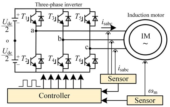
Figure 1.
Inverter-Induction Motor System Topology Diagram.
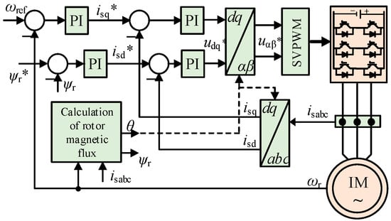
Figure 2.
Block Diagram of FOC for Induction Motor.
The motor speed is obtained by the speed sensor and fed into the outer loop PI controller to generate a q-axis current reference value. Similarly, the motor magnetic flux is also fed into the PI controller to generate the q-axis current reference value. Combined with sampled phase currents through coordinate transformation, the inner-loop PI controllers complete current closed-loop control. Finally, the modulated voltage is converted into PWM signals via space vector modulation (SVM) to drive the inverter and motor.
Based on [27,32], the three-phase inverter output phase voltage can be derived as
where uan, ubn, ucn represents motor phase voltages; Si represents switching state of the i-th IGBT (1 for ON, 0 for OFF, where i = 1~6); and Udc represents DC-link voltage.
The switching signals satisfy the complementary constraint [27]
The motor state equations in the α-β stationary reference frame are expressed as [33]
where λ = (Rs + Lm2/(LrTr))/(σLs), K = Lm/(σLsLr), σ = 1 − Lm2/(LsLr), Tr = Lr/Rr. Rs and Rr represent stator and rotor resistances respectively. Ls and Lr represent stator and rotor inductances respectively. Lm is mutual inductance between stator and rotor. isα and isβ are α-β-axis stator current components. usα and usβ are α-β-axis stator voltage components. ψrα and ψrβ are α-β-axis rotor flux components.
To address the solution of Equation (3), two primary approaches are generally considered in computational analysis. The first involves deriving an analytical solution through mathematical decomposition techniques [34]. However, this method often becomes computationally intensive and impractical due to the inherent complexity of nonlinear differential equations. The second approach employs numerical discretization methods, which approximate solutions with controlled accuracy while significantly reducing computational overhead. For this study, the latter strategy is adopted. Runge Kutta method is a commonly used method for solving differential equations [32]. In this study, the fourth-order Runge-Kutta (RK4) method is employed to linearize the governing differential equations. The mathematical representation of Equation (3) is formulated as
where isα,n, isβ,n, ψrα,n, ψrβ,n and isα,n+1, isβ,n+1, ψrα,n+1, ψrβ,n+1 are the current and rotor flux at the n step and the (n + 1) step respectively, h is the computational step size between time instants tn and tn+1, Ka1~Ka4, Kb1~Kb4, Kc1~Kc4 and Kd1~Kd4 are the coefficients, which are shown as
where f = [isα,n+1, isβ,n+1, ψrα,n+1, ψrβ,n+1].
In addition, h can be determined by the event-driven digital model solver as shown in Figure 3 [35]. In this work, the intersection points of the modulating and carrier waves are used as discrete events to set the step size of twin models, improving computational speed while maintaining sufficient accuracy.
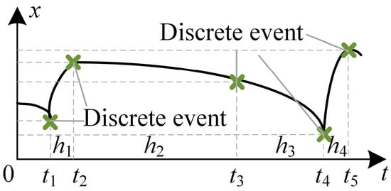
Figure 3.
Principle Diagram of Event-Driven Solving Method.
The digital model of the inverter-driven induction motor is finally obtained as
where coefficients f1~f4 are related to parameters (Rs, Ls, Rr, Lr, Lm) and switching signals Si. Based on this framework, the digital twin model for induction motors under healthy conditions can be established, with modulating signals and rotor speed as inputs, and stator phase currents as outputs. When provided with corresponding inputs, this digital twin model is capable of emulating the current responses of normal operating motors.
3. Stator Inter-Turn Short Circuit Fault Diagnosis Method Based on Digital Twin Technology
3.1. Mathematical Model of Stator Inter-Turn Short Circuit Fault in Induction Motor
Figure 4 presents the equivalent model of stator inter-turn short circuit faults in induction motor windings. It can be observed that two critical parameters emerge during stator inter-turn short circuit faults: the fault phase parameter and the fault severity parameter. The fault phase parameter θtf is defined with discrete values 0, 2π/3, and 4π/3 corresponding to stator phase-A, B, and C short circuits respectively. The fault severity parameter ηtf is equal to the ratio of the number Ns of short-circuit turns in the short-circuit phase to the total number N of turns in that phase. According to literature [36], when a fault occurs, only the fault-related parameters undergo changes. The fundamental electrical parameters of the motor predominantly vary with thermal state and magnetic saturation level, maintaining independence from fault conditions. Consequently, the voltage and flux linkage equations of the faulty motor in the two-phase stationary reference frame are formulated in (7)–(12).
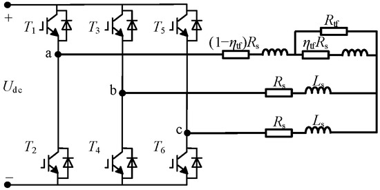
Figure 4.
Equivalent Circuit Model for Phase A Stator Turn-to-Turn Short-Circuit Fault in Induction Motors.
The electromechanical motion equation of the motor can be expressed as
By combining Equations (7)–(14), the state-space equations of an induction motor with stator inter-turn short-circuit in the two-phase stationary reference frame can be derived, which facilitates further analysis and digital simulations.
3.2. Current Residual-Based Fault Diagnosis Method
A motor digital twin model based on health state can predict the stator current during operation. By comparing the predicted current with the sensor-sampled current, the current residual is obtained for inter-turn short-circuit fault diagnosis. Under the stationary coordinate frame, the voltage equation of a healthy motor is
By substituting Equation (9) into Equation (6), we can obtain
Furthermore, the current residual in the α-β coordinate frame can be derived as
Define the sum of squares of the current residuals on the α-β axes as
Additionally, the fault current can be expressed as
where Itf and θ0 are the amplitude and initial phase angle of the fault current, respectively.
Therefore, Equation (18) can be rewritten as
It can be observed that the sum of squared current residuals on the α-β axes contains both a DC component and a twice-frequency component, which can be utilized to diagnose the occurrence of inter-turn short-circuit faults.
3.3. Digital Twin-Based Fault Detection and Fault Localization
This paper selects the DC component for fault detection, considering that the fault current is positively correlated with the rotational speed [37]. The fault detection index is
After an inter-turn short circuit fault is detected, fault localization must be performed to identify the affected winding segment. In this paper, the squared current residual in the three-phase stationary coordinate system is defined as the Fault Location index, as shown in (22). The three-phase current residuals are obtained by comparing the sampled motor currents with the outputs of a digital twin model. Under healthy motor conditions, these residuals remain minimal, primarily attributed to model inaccuracies and sensor noise. When an inter-turn short-circuit fault occurs, the digital twin model designed to simulate normal motor behavior fails to replicate the fault-induced current distortion. Consequently, the residual of the faulted phase exhibits significant amplification. A pronounced residual imbalance, where one phase residual substantially exceeds the others, provides deterministic evidence for identifying the faulted phase [38].
The architecture of the fault detection and localization method is illustrated in Figure 5. Initially, a digital twin model is constructed based on the healthy motor’s mathematical framework. By integrating an event-driven model-solving approach, real-time computation of three-phase currents is achieved. Through the scheduled application of Particle Swarm Optimization intelligent algorithm, systematic identification of key operational parameters in physical systems is achieved, enabling precise emulation of the physical motor’s operational states. Subsequently, the sum of squared current residuals in the α-β coordinate system is calculated to derive the fault detection index. If the index exceeds a predefined threshold, a fault is determined to have occurred. Upon fault detection, the squared residuals of the three-phase stationary coordinate system currents are analyzed to localize the fault.
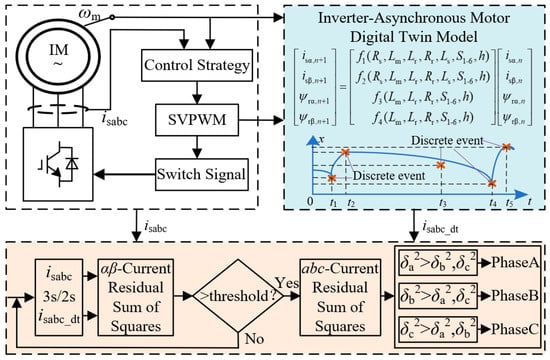
Figure 5.
Block Diagram of Inter-Turn Short Circuit Fault Diagnosis.
4. Simulation Verification
To validate the effectiveness of the proposed fault diagnosis method, a simulation model for stator inter-turn short-circuit faults in an induction motor is developed in MATLAB/Simulink. The motor parameters used in the simulation are listed in Table 1.

Table 1.
Induction Motor Parameters.
4.1. Simulation Verification of Healthy Motor Digital Twin Model
Figure 6 illustrates the simulation waveforms of the phase-A stator current for both the physical motor and its corresponding digital twin model under steady-state operating conditions, specifically at a motor speed of 300 r/min. Figure 7 further demonstrates the simulated phase-A current waveforms of the motor and digital twin model during a transient event characterized by a sudden speed increase. The results reveal that the digital twin model accurately replicates the output characteristics of the physical motor across both steady-state and dynamic conditions. As shown in Figure 6 and Figure 7, the output A-phase current from the established digital twin model closely matches the actual A-phase current waveforms under both steady-state and dynamic conditions. This demonstrates that the digital twin model accurately replicates the physical motor’s output characteristics across varying operational regimes. The digital twin achieves high-fidelity emulation of motor dynamics. This capability provides a robust technical basis for detecting stator winding inter-turn faults through precise behavioral replication. The consistent alignment between the motor and digital twin outputs validates the model’s effectiveness and its potential for accurate fault detection and analysis.
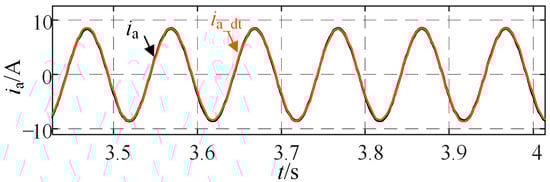
Figure 6.
Simulation Waveforms of Phase-A Current for Motor and Digital Twin Model Under Steady-State Conditions.
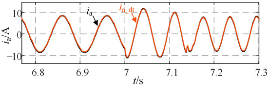
Figure 7.
Simulation Waveforms of Phase-A Current for Motor and Digital Twin Model During Sudden Speed Change.
4.2. Validation of Fault Diagnosis Methods
Figure 8 presents the simulated waveforms of three-phase stator currents under fault conditions with a motor speed of 500 r/min, a load of 3 N·m, and a fault occurring in phase A (fault severity parameter ηtf = 0.0351). Figure 9 displays the simulated electromagnetic torque waveform under fault conditions. It can be observed that the stator current slightly decreases while the electromagnetic torque pulsation increases during inter-turn short-circuit faults.
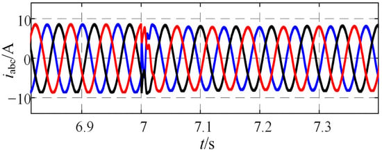
Figure 8.
Simulation Waveforms of Three-Phase Stator Currents for Motor Under Fault Conditions.
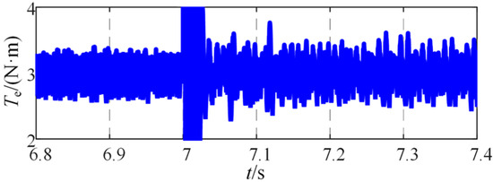
Figure 9.
Simulation Waveforms of Electromagnetic Torque for Motor Under Fault Conditions.
Figure 10 shows the inter-turn short-circuit fault diagnosis results under different speed conditions with a load of 3 N·m. It can be observed that after fault occurrence, the FD indicator increases rapidly, while the fault localization indicator accurately identifies phase A as the faulty phase. Notably, the FD indicator exhibits low sensitivity to speed variations. Figure 11 presents the fault diagnosis results under different load conditions at a constant speed of 500 r/min. The results demonstrate that the FD indicator promptly responds to fault inception, and the localization indicator consistently pinpoints phase A as the fault location. Figure 12 illustrates the diagnosis results under varying fault severity levels (speed: 500 r/min, load: 3 N·m), where the FD indicator magnitude increases proportionally with the fault severity. Figure 13 displays the fault localization performance for phase C faults, confirming the indicator’s capability to precisely identify phase C as the fault location.
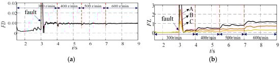
Figure 10.
Diagnosis Results of Inter-Turn Short Circuit Faults Under Different Rotational Speeds (a) Fault Diagnosis Index FD (b) Fault Phasing Index FL.
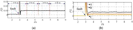
Figure 11.
Diagnosis Results of Inter-Turn Short Circuit Faults Under Different Load Conditions (a) Fault Diagnosis Index FD (b) Fault Phasing Index FL.
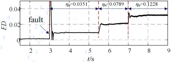
Figure 12.
Diagnosis Results of Inter-Turn Short Circuit Faults Under Different Fault Severity Levels.
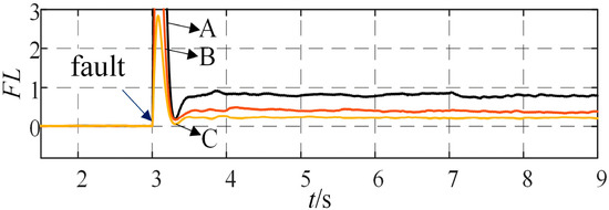
Figure 13.
Results of Fault Location Indicators Under Phase C Fault Conditions.
4.3. Comparison of Current Predictive Methods
The fault detection method in this chapter primarily hinges on the acquisition of current residuals, which predominantly relies on the digital twin model for current value prediction. Alternatively, the current value can also be predicted based on the mathematical model of the motor and the current sampling value from the previous time step. However, in this case, the obtained current residual only reflects the current variation within a single sampling period. Moreover, since the previous sampling value already contains fault information, the fault characteristics in the calculated current residual may become less pronounced.
In contrast, the digital twin operates in parallel with the actual system, reflecting its real-time operational state. The key distinction lies in the fact that the digital twin model predicts the current for the next time step based on its output, without utilizing sampled values. In the event of a fault, the digital twin continues to compute based on the healthy-state motor model, causing the error between the actual system output and the digital twin’s output to accumulate over time, thereby amplifying the fault characteristics.
It is important to note, however, that once a fault is detected, the digital twin model must not adopt the motor parameters identified post-fault. Instead, it should retain the pre-fault (healthy-state) motor parameters for computation. This can be addressed by periodically saving the motor identification results during normal operation.
As shown in Figure 14, a comparative analysis of fault diagnosis results under different prediction methods was conducted. The results demonstrate that the fault index amplitude obtained using the digital twin-based current prediction is approximately 20 times greater than that derived from sampled-value-based current prediction. Consequently, the proposed method exhibits a more pronounced fault index, confirming its superior effectiveness.
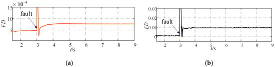
Figure 14.
Fault Diagnosis Results Comparison for Current Values Under Different Prediction Methods (a) Current Value Prediction Using Sampled Values (b) Current Value Prediction Using Digital Twin Model.
5. Experimental Verification
5.1. Experimental Platform
To further verify the effectiveness of the proposed fault diagnosis method in practical applications, a three-phase two-level inverter-driven induction motor experimental prototype was constructed, as shown in Figure 15. The system configuration comprised a high-voltage DC power supply connected to the input side of the inverter, which in turn drove a modified low-power induction motor on the output side. To simulate real-world operating conditions, the frequency converter was configured to operate in torque mode, enabling precise control of the motor’s load characteristics. The core of the experimental platform was centered around the TMS320F28335 digital signal processor (DSP), serving as the master control chip for system operation and data acquisition. The monitoring system incorporates precision current transducers at strategic measurement nodes. These sensors continuously acquire fault loop current waveforms, which are then routed to a high-fidelity oscilloscope for real-time visualization and diagnostic analysis. Additionally, critical fault indicators and diagnostic information were extracted and converted into analog signals through an external digital-to-analog converter module, allowing for simultaneous visualization on the oscilloscope. The modular experimental platform delivers dual technical functions: (1) Algorithm validation: Enables rigorous testing of the novel fault diagnosis method; (2) Behavioral analysis: Supports systematic evaluation of system responses under simulated fault scenarios. These experimental capabilities collectively demonstrate the solution’s technical readiness for industrial deployment.
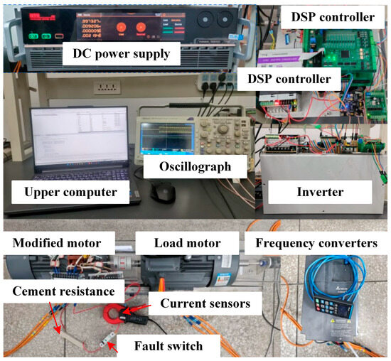
Figure 15.
Experimental platform.
The fault motor used in the experiment was modified from a standard 1.5 kW low-power induction motor. During the modification process, the stator windings were carefully rewound, with multiple taps extracted at predetermined turns to allow precise simulation of inter-turn short-circuit faults. These taps were externally connected via a switch mechanism, enabling controlled fault initiation through manual or automated switching operations. To address safety concerns and replicate realistic fault conditions, a current-limiting resistor was integrated in series between the taps, effectively controlling the short-circuit current magnitude. This precaution was particularly crucial as inter-turn faults typically generate excessively high currents that could potentially damage the motor or measurement equipment. The modified design provided a reliable and safe platform for studying fault characteristics under controlled conditions. This methodology has been widely adopted by other researchers in related studies, such as reference [39,40,41].
Each phase of the induction motor comprises six coils connected in series, with 38 turns per coil, totaling 228 turns per phase. Seven taps were extracted, allowing the experimental platform to simulate short-circuit faults with varying numbers of turns and corresponding short-circuit turn ratios (μ), as detailed in Table 2. The platform can simulate a minimum of 1 turn and a maximum of 19 turns of short-circuit faults. By connecting the faulted phase of the motor to different output phases of the inverter, inter-turn short-circuit faults in different motor phases can be emulated.
Table 2.
Fault simulation experimental conditions.
To prevent irreversible damage to the motor caused by large fault currents during inter-turn short-circuit faults, experiments were conducted under low DC voltage (200 V), low speed, and low load conditions. Since the stator windings of the motor were rewound, and considering potential variations in motor parameters, the parameters of the induction motor were measured after the rewinding process. The obtained parameters are listed in Table 3.
Table 3.
Modified Induction Motor Parameters.
5.2. Experimental Validation of Healthy Motor Digital Twin Model
Figure 16 illustrates the comparative analysis of steady-state A-phase stator current waveforms between the physical motor and its digital twin model, demonstrating remarkable consistency in amplitude, frequency, and phase characteristics. The corresponding three-phase current residual waveforms, presented in Figure 17, further validate the accuracy of the digital twin implementation, showing minimal deviations between the simulated and actual system responses. These experimental results collectively confirm that the developed digital twin model successfully captures the essential operational characteristics of the physical prototype, with output behaviors maintaining fundamental consistency across various operational parameters. The close alignment between the digital twin and physical system responses underscores the model’s reliability for fault diagnosis and system analysis applications.
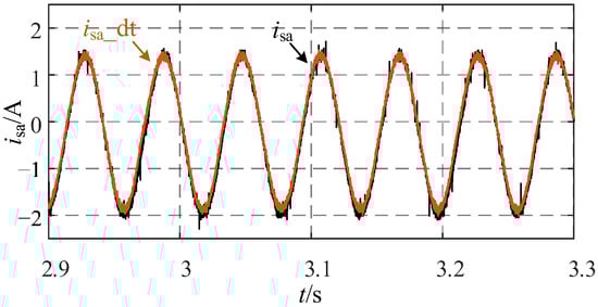
Figure 16.
A-Phase Stator Current in a Healthy State.
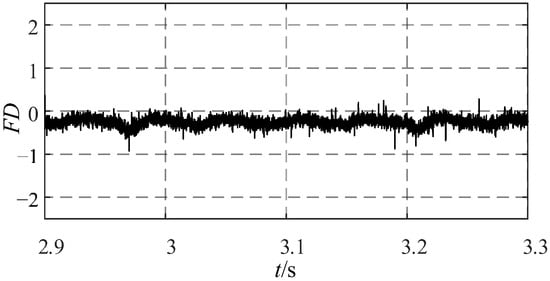
Figure 17.
Residual Stator Current of Phase A in a Healthy State.
5.3. Validation of the Fault Diagnosis Methodology
The proposed algorithm for diagnosing inter turn short circuit faults in asynchronous motor stator windings based on digital twins was validated on a fault experimental platform. Figure 18 shows the comparison of stator current in the two-phase coordinate system before and after the addition of stator winding turn to turn short circuit fault. It can be seen that after adding the A-phase fault, the alpha axis current increases significantly, and the corresponding current residual increases. Figure 19 shows the waveforms of various signals under the inter turn short circuit fault of the A-phase stator winding. During the experiment, a current clamp was used to measure the current at the short circuit winding, which is the fault current, in order to facilitate the observation of the time of adding the fault and the fault diagnosis effect. As shown in Figure 19, after adding the inter turn short circuit fault of the A-phase stator winding, the fault diagnosis index FD rapidly increases, and the fault diagnosis signal Fault jumps to 1, indicating a fault has occurred. Subsequently, the fault phase positioning signal FL jumps to 3, indicating a fault in the A-phase winding.
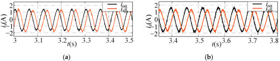
Figure 18.
Comparison of Stator Current Before and After Fault. (a) Health Condition. (b) Interturn Short Circuit Fault.
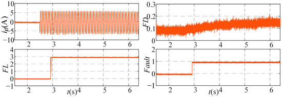
Figure 19.
Signal Waveforms for A-Phase Inter Turn Short Circuit Fault.
Figure 20 showcases the diagnostic performance of the proposed method for inter-turn short-circuit faults with varying severity levels under a constant speed condition of 500 rpm. The figure illustrates fault index values (FD) and phase A current variations under C-phase short-circuit faults at 2, 7, 12, and 19 turns. It shows that as the number of faulty turns increases from 2 to 19, the FD rises gradually from 0.2 to 0.3, while the amplitude of phase A current also increases progressively. The experimental results demonstrate a clear correlation between fault severity and diagnostic parameters: as the number of shorted turns increases, both the fault current in the circuit and the corresponding fault index value show progressive and measurable increments. The diagnostic parameters exhibit linear correlation with fault severity progression. This trend conclusively demonstrates the method’s dual capability in both identifying and precisely measuring stator inter-turn insulation degradation levels. Experimental data validate the diagnostic method’s consistency under multi-scenario fault operations. This capability proves its technical viability for detecting stator insulation degradation in industrial motor systems.
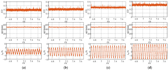
Figure 20.
Diagnostic Results for Faults with Varying Numbers of Shorted Turns Under a Constant 500 Rpm Speed Condition (a) 2-Turn Fault in Phase C (b) 7-Turn Fault in Phase C (c) 12-Turn Fault in Phase C (d) 19-Turn Fault in Phase C.
In addition, Figure 21 shows the waveform of the fault diagnosis signal when the rotor resistance deviates by 20% in the controller. It can be seen that even when the control parameters are mismatched, the fault diagnosis algorithm can still quickly diagnose the fault and locate the fault phase.
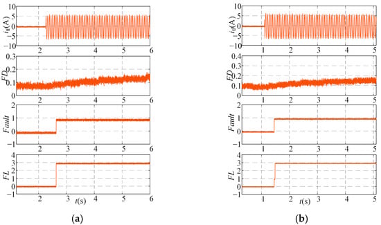
Figure 21.
Signal Waveforms of A-Phase Inter Turn Short Circuit Fault When Rotor Resistance Mismatch Occurs. (a) 20% Larger. (b) 20% Smaller.
Finally, Figure 22 demonstrates the diagnostic performance of the proposed methodology under dynamic variable-speed operating conditions. The motor transitions from a healthy state to a 12-turn short-circuit fault in Phase C at a commanded speed of 600 rpm. During the test, the motor speed was continuously varied to evaluate the robustness of the diagnostic system. The results reveal a rapid and significant increase in the diagnostic index immediately following the fault inception, clearly indicating the detection of the inter-turn short-circuit condition. Furthermore, as the commanded speed was progressively increased, the diagnostic index showed a corresponding elevation while consistently maintaining its sensitivity to the fault characteristics. This behavior demonstrates the methodology’s capability to adapt to changing operational conditions without compromising fault detection accuracy. The experimental outcomes conclusively validate the effectiveness and reliability of the proposed diagnostic approach in handling real-world variable-speed scenarios, highlighting its potential for practical industrial applications where motor speed fluctuations are common.
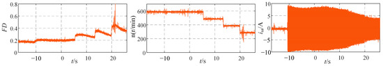
Figure 22.
Diagnostic Results Under Variable-Speed Operating Conditions.
6. Conclusions
This paper proposes an online digital twin-based method for diagnosing inter-turn short-circuit faults in induction motor stator windings. This method establishes a real-time digital twin model of an induction motor, combines the characteristics of stator winding turn to turn short circuit faults, compares the three-phase currents in the actual motor and the digital twin model, and achieves fault detection and localization. The simulation and experimental results have verified the effectiveness of the proposed fault diagnosis and localization method. Its advantages include:
- The fault index amplitude of the proposed method is about 20 times that of the traditional predictive method, yielding significantly enhanced diagnostic sensitivity due to more pronounced fault characteristics.
- The method maintains real-time fault diagnosis capability even under motor parameter mismatch conditions, exhibiting superior performance compared to the traditional predictive method.
- The approach is completely non-invasive, requiring no additional measurement instrumentation.
- The solution exhibits strong robustness across various motor speed operating conditions.
The proposed method holds significant importance for condition monitoring and fault diagnosis in motor drive systems, with potential application value in various industrial environments where motor reliability is critical.
Author Contributions
Conceptualization, Y.C. and L.Z.; methodology, Y.C.; software, K.L.; validation, Y.C., K.L. and C.Y.; formal analysis, K.L.; investigation, L.L.; resources, L.Z.; data curation, Y.C.; writing—original draft preparation, C.Y.; writing—review and editing, C.Y.; visualization, C.Y.; supervision, L.L.; project administration, L.L.; funding acquisition, L.Z. All authors have read and agreed to the published version of the manuscript.
Funding
This research was funded by the China Academy of Railway Sciences Corporation Limitec Foundation Project, grant number 2023YJ247 and the Scientific Research Projects of China Association of Metros, grant number CAMET-KY2022039.
Data Availability Statement
The original contributions presented in the study are included in the article, further inquiries can be directed to the corresponding author.
Conflicts of Interest
Authors Yujie Chen, Leiting Zhao, Liran Li and Kan Liu were employed by the Beijing Zongheng Electromechanical Technology Co., Ltd. The remaining authors declare that the research was conducted in the absence of any commercial or financial relationships that could be construed as a potential conflict of interest.
References
- Deng, L.; Chen, Y.; Wu, R.; Wang, Q.; Xu, Y. A two-dimensional clustering method for high-speed railway trains in China based on train characteristics and operational performance. IEEE Access 2020, 8, 81918–81931. [Google Scholar] [CrossRef]
- Wang, Y.; Zhu, S.; Li, S.; Yang, L.; De Schutter, B. Hierarchical model predictive control for on-line high-speed railway delay management and train control in a dynamic operations environment. IEEE Trans. Control Syst. Technol. 2022, 30, 2344–2359. [Google Scholar] [CrossRef]
- Surya, G.N.; Khan, Z.J.; Ballal, M.S.; Suryawanshi, H.M. A simplified frequency-domain detection of stator turn fault in squirrel-cage induction motors using an observer coil technique. IEEE Trans. Ind. Electron. 2017, 64, 1495–1506. [Google Scholar] [CrossRef]
- Almounajjed, A.; Sahoo, A.K.; Kumar, M.K.; Subudhi, S.K. Stator fault diagnosis of induction motor based on discrete wavelet analysis and neural network technique. Chin. J. Elect. Eng. 2023, 9, 142–157. [Google Scholar] [CrossRef]
- Nguyen, V.; Seshadrinath, J.; Wang, D.; Nadarajan, S.; Vaiyapuri, V. Model-based diagnosis and RUL estimation of induction machines under interturn fault. IEEE Trans. Ind. Appl. 2017, 53, 2690–2701. [Google Scholar] [CrossRef]
- Wolkiewicz, M.; Tarchała, G.; Orłowska-Kowalska, T.; Kowalski, C.T. Online stator interturn short circuits monitoring in the DFOC induction-motor drive. IEEE Trans. Ind. Electron. 2016, 63, 2517–2528. [Google Scholar] [CrossRef]
- Abdallah, H.; Benatman, K. Stator winding inter-turn short-circuit detection in induction motors by parameter identification. IET Elect. Power Appl. 2017, 11, 272–288. [Google Scholar] [CrossRef]
- Cheng, M.; Hang, J.; Zhang, J. Overview of fault diagnosis theory and method for permanent magnet machine. Chin. J. Electron. Eng. 2015, 1, 21–36. [Google Scholar]
- Mazzoletti, M.A.; Bossio, G.R.; De Angelo, C.H.; Espinoza-Trejo, D.R. A model-based strategy for interturn short-circuit fault diagnosis in PMSM. IEEE Trans. Ind. Electron. 2017, 64, 7218–7228. [Google Scholar] [CrossRef]
- Hu, R.; Wang, J.; Mills, A.R.; Chong, E.; Sun, Z. Current-Residual-Based Stator Interturn Fault Detection in Permanent Magnet Machines. IEEE Trans. Ind. Electron. 2021, 68, 59–69. [Google Scholar] [CrossRef]
- Ray, S.; Dey, D. Development of a comprehensive analytical model of induction motor under stator interturn faults incorporating rotor slot harmonics. IEEE Trans. Ind. Electron. 2023, 70, 2037–2047. [Google Scholar] [CrossRef]
- Babu, A.C.; Seshadrinath, J. Interacting multiple model framework for incipient diagnosis of interturn faults in induction motors. IEEE Trans. Artif. Intell. 2024, 5, 5120–5129. [Google Scholar] [CrossRef]
- Jeong, H.; Moon, S.; Kim, S.W. An early stage interturn fault diagnosis of PMSMs by using negative-sequence components. IEEE Trans. Ind. Electron. 2017, 64, 5701–5708. [Google Scholar] [CrossRef]
- Irhoumah, M.; Pusca, R.; Lefevre, E.; Mercier, D.; Romary, R. Detection of the stator winding inter-turn faults in asynchronous and synchronous machines through the correlation between harmonics of the voltage of two magnetic flux sensors. IEEE Trans. Ind. Appl. 2019, 55, 2682–2689. [Google Scholar] [CrossRef]
- Gan, C.; Wu, J.; Yang, S.; Hu, Y.; Cao, W. Wavelet Packet Decomposition-Based Fault Diagnosis Scheme for SRM Drives with a Single Current Sensor. IEEE Trans. Energy Convers. 2016, 31, 303–313. [Google Scholar] [CrossRef]
- Bakhri, S.; Ertugrul, N.; Soong, W.L. Negative sequence current compensation for stator shorted turn detection in induction motors. In Proceedings of the IECON 2012—38th Annual Conference on IEEE Industrial Electronics Society, Montreal, QC, Canada, 25–28 October 2012; pp. 1921–1926. [Google Scholar]
- Ebrahimi, B.M.; Faiz, J. Feature extraction for short-circuit fault detection in permanent-magnet synchronous motors using stator-current monitoring. IEEE Trans. Power Electron. 2010, 25, 2673–2682. [Google Scholar] [CrossRef]
- Wei, D.; Liu, K.; Hu, W.; Peng, X.; Chen, Y.; Ding, R. Short-time adaline based fault feature extraction for inter-turn short circuit diagnosis of PMSM via residual insulation monitoring. IEEE Trans. Ind. Electron. 2023, 70, 3103–3114. [Google Scholar] [CrossRef]
- Eftekhari, M.; Moallem, M.; Sadri, S.; Hsieh, M.-F. Online detection of induction motor’s stator winding short-circuit faults. IEEE Syst. J. 2014, 8, 1272–1282. [Google Scholar] [CrossRef]
- Ayas, S.; Ayas, M.S. A novel bearing fault diagnosis method using deep residual learning network. Multimed. Tools Appl. 2022, 81, 22407–22423. [Google Scholar] [CrossRef]
- Maraaba, L.S.; Milhem, A.S.; Nemer, I.A.; Al-Duwaish, H.; Abido, M.A. Convolutional neural network-based inter-turn fault diagnosis in LSPMSMs. IEEE Access 2020, 8, 81960–81970. [Google Scholar] [CrossRef]
- Abid, F.B.; Sallem, M.; Braham, A. Robust interpretable deep learning for intelligent fault diagnosis of induction motors. IEEE Trans. Instrum. Meas. 2020, 69, 3506–3515. [Google Scholar] [CrossRef]
- Husari, F.; Seshadrinath, J. Early stator fault detection and condition identification in induction motor using novel deep network. IEEE Trans. Artif. Intell. 2022, 3, 809–818. [Google Scholar] [CrossRef]
- Fang, Y.; Wang, M.; Wei, L. Deep transfer learning in inter-turn short circuit fault diagnosis of PMSM. In Proceedings of the 2021 IEEE International Conference on Mechatronics and Automation (ICMA), Takamatsu, Japan, 8–11 August 2021; pp. 489–494. [Google Scholar]
- Oner, M.U.; Şahin, İ.; Keysan, O. Neural networks detect inter-turn short circuit faults using inverter switching statistics for a closed-loop controlled motor drive. IEEE Trans. Energy Convers. 2023, 38, 2387–2395. [Google Scholar] [CrossRef]
- Guo, Z.; Yan, S.; Xu, X.; Chen, Z.; Ren, Z. Twin-model based on model order reduction for rotating motors. IEEE Trans. Magn. 2022, 58, 8206304. [Google Scholar] [CrossRef]
- Song, W.; Zou, Y.; Ma, C.; Zhang, S. Digital twin modeling method of three-phase inverter-driven PMSM systems for parameter estimation. IEEE Trans. Power Electron. 2024, 39, 2360–2371. [Google Scholar] [CrossRef]
- Jain, P.; Poon, J.; Singh, J.P.; Spanos, C.; Sanders, S.R.; Panda, S.K. A digital twin approach for fault diagnosis in distributed photovoltaic systems. IEEE Trans. Power Electron. 2020, 35, 940–956. [Google Scholar] [CrossRef]
- Zhang, S.; Song, W.; Cao, H.; Tang, T.; Zou, Y. A digital-twin-based health status monitoring method for single-phase PWM rectifiers. IEEE Trans. Power Electron. 2023, 38, 14075–14087. [Google Scholar] [CrossRef]
- Li, W.; Xu, Z.; Zhang, Y. Induction motor control system based on FOC algorithm. In Proceedings of the 2019 IEEE 8th Joint International Information Technology and Artificial Intelligence Conference (ITAIC), Chongqing, China, 24–26 May 2019; pp. 1544–1548. [Google Scholar]
- Castiglia, V.; Ciotta, P.; Di Tommaso, A.O.; Miceli, R.; Nevoloso, C. High performance FOC for induction motors with low cost ATSAM3X8E microcontroller. In Proceedings of the 2018 7th International Conference on Renewable Energy Research and Applications (ICRERA), Paris, France, 14–17 October 2018; pp. 1495–1500. [Google Scholar]
- Song, W.; Zhang, Z.; Zhang, S.; Ma, C.; Li, J. Digital twin modeling and multiparameter monitoring schemes of three-level ANPC inverters. IEEE Trans. Power Electron. 2024, 39, 16596–16608. [Google Scholar] [CrossRef]
- Yang, G.; Zhao, X.; Guan, T.; Eldeeb, H.H.; Kang, J.; Zhan, Y.; Cui, X.; Xu, G.; Zhao, H. Parameter Identification Based on Equivalent Impedance and Back-EMF during Shut-Down Process of Induction Motors. In Proceedings of the 2023 IEEE Energy Conversion Congress and Exposition (ECCE), Nashville, TN, USA, 29 October–2 November 2023; pp. 4949–4953. [Google Scholar]
- Li, B.X.; Low, K.S. Low sampling rate online parameters monitoring of DC-DC converters for predictive-maintenance using biogeography-based optimization. IEEE Trans. Power Electron. 2016, 31, 2870–2879. [Google Scholar] [CrossRef]
- Zhu, Y.; Zhao, Z.; Shi, B.; Yu, Z. Discrete state event-driven framework with a flexible adaptive algorithm for simulation of power electronic systems. IEEE Trans. Power Electron. 2019, 34, 11692–11705. [Google Scholar] [CrossRef]
- Lee, J.; Moon, S.; Jeong, H.; Kim, S.W. Robust Diagnosis Method Based on Parameter Estimation for an Interturn Short-Circuit Fault in Multipole PMSM under High-Speed Operation. Sensors 2015, 15, 29452–29466. [Google Scholar] [CrossRef] [PubMed]
- Urresty, J.-C.; Riba, J.-R.; Romeral, L. Diagnosis of interturn faults in PMSMs operating under nonstationary conditions by applying order tracking filtering. IEEE Trans. Power Electron. 2013, 28, 507–515. [Google Scholar] [CrossRef]
- Chen, Z.; Liang, D.; Jia, S.; Yang, L.; Yang, S. Incipient interturn short-circuit fault diagnosis of permanent magnet synchronous motors based on the data-driven digital twin model. IEEE J. Emerg. Sel. Top. Power Electron. 2023, 11, 3514–3524. [Google Scholar] [CrossRef]
- Jia, Z.; Song, W.; Ma, C.; Zhang, B.; Sun, N. An MPC-Based Online Interturn Fault Diagnosis Method for Induction Motors with Fault Localization. IEEE Trans. Transp. Electrific. 2025, 11, 75–85. [Google Scholar] [CrossRef]
- Hang, J.; Zhang, J.; Cheng, M.; Huang, J. Online Interturn Fault Diagnosis of Permanent Magnet Synchronous Machine Using Zero-Sequence Components. IEEE Trans. Power Electron. 2015, 30, 6731–6741. [Google Scholar] [CrossRef]
- Hu, J.; Wang, H.; Wei, F.; Li, C.; Li, Y. Simplified pre-analysis of fault severity for interturn short-circuit faults in fault-tolerant permanent magnet machines. IEEE Trans. Ind. Electron. 2025, 72, 2160–2164. [Google Scholar] [CrossRef]
Disclaimer/Publisher’s Note: The statements, opinions and data contained in all publications are solely those of the individual author(s) and contributor(s) and not of MDPI and/or the editor(s). MDPI and/or the editor(s) disclaim responsibility for any injury to people or property resulting from any ideas, methods, instructions or products referred to in the content. |
© 2025 by the authors. Licensee MDPI, Basel, Switzerland. This article is an open access article distributed under the terms and conditions of the Creative Commons Attribution (CC BY) license (https://creativecommons.org/licenses/by/4.0/).