Article

Research on the Maximum Regenerative Energy Commutation Control Strategy of a Dual-Mode Synergistic Energy Recovery Pump-Controlled Grinder

1
School of Mechanical Engineering, Yanshan University, Qinhuangdao 066004, China
2
Xinjiang Coal Mine Electromechanical Engineering Technology Research Center, Xinjiang Institute of Engineering, Urumqi 830023, China
3
Key Laboratory of Xinjiang Coal Resources Green Mining, Ministry of Education, Xinjiang Institute of Engineering, Urumqi 830023, China
4
College of Mechanical and Aerospace Engineering, Jilin University, Changchun 130025, China
*
Author to whom correspondence should be addressed.
Energies 2025, 18(10), 2622; https://doi.org/10.3390/en18102622
Submission received: 7 April 2025 / Revised: 30 April 2025 / Accepted: 14 May 2025 / Published: 19 May 2025

Abstract

Large-inertia pump-controlled grinding machines experience significant energy loss and potential hydraulic shock during frequent high-speed table reciprocation. Traditional control methods often neglect to address efficient energy recovery during the dynamic commutation phase. This study proposes and investigates a dual-mode synergistic energy recovery system that combines motor regeneration and accumulator storage for pump-controlled grinders. The primary focus of this study is on developing a maximum regenerative energy commutation control strategy. A mathematical model of the system was established, and extensive simulations were performed to analyze the energy recovery process under varying load mass, initial velocity, and leakage coefficient conditions. Machine learning models were compared for predicting the peak time of total recovered energy, with a neural network (NN) demonstrating superior accuracy (R2 ≈ 0.99997). An adaptive commutation strategy was designed, utilizing the NN prediction corrected by a confidence score based on historical and test data ranges, to determine the optimal moment for initiating reverse motion. The strategy was validated using Simulink–Amesim co-simulation and experiments conducted on a 10-ton test bench. The results show that the proposed strategy effectively maximizes energy capture; experiments indicate a 14.3% increase in energy recovery efficiency and a 25% reduction in commutation time compared to a fixed timing approach. The proposed commutation strategy also leads to faster settling to steady-state velocity and smoother operation, while the accumulator demonstrably reduces pressure peaks. This research provides a robust method for enhancing energy efficiency and productivity in pump-controlled grinding applications by improving regenerative braking control through a predictive commutation strategy.

1. Introduction

The grinding machine is the core equipment for precision machining. The table reciprocating motion requires frequent direction changes, and the load inertia is significant. The mass of the workpiece platform of the 10 m grinding machine reaches 15,000 kg–30,000 kg, and the energy consumption is high. The traditional valve-controlled hydraulic system relies on throttling to regulate speed, which generates substantial throttling losses and low energy efficiency during the direction change process [1]. The braking phase is prone to causing violent hydraulic shock and mechanical oscillation, which not only exacerbates the waste of energy but also leads to a decline in machining accuracy, particularly when machining large inertia loads [2]. The volumetric speed control characteristics of the pump-controlled hydraulic system can eliminate throttling losses and effectively improve the energy efficiency of the system [3]. The four-quadrant technology of the pump-controlled system also allows the energy to flow in both directions, and the kinetic energy is converted into electrical energy through pump-driven motor power generation at the time of commutation, which improves energy utilization [4,5]. Therefore, this study proposes a new configuration of a pump-controlled grinder. As the working conditions during energy recovery may not necessarily reach the optimal efficiency of the motor, which may lead to insufficient recovery of some energy, accumulators are also commonly used in hydraulic systems for energy recovery [6]. However, accumulators are limited by volume and pressure fluctuations, cannot store energy for a long time, and are prone to causing secondary impacts when energy is released directly. The pump-controlled grinder also requires the selection of an appropriate time to start the motor during the braking energy recovery phase to carry out the commutation of the grinder’s reciprocating motion. In this study, the dual-mode synergy between the accumulator and the motor is used to achieve high-efficiency kinetic energy recovery for pump-controlled grinding machines, and the commutation control strategy is studied to improve the energy recovery efficiency of large-load grinding machines and achieve smooth and fast commutation.
A large number of studies have been carried out by different scholars to investigate energy-saving strategies for grinding machines, energy-saving strategies for hydraulic systems, and energy recovery. In terms of energy saving in grinding machines, Wang et al. [7] proposed a decision-making expert system based on monitoring power data that reduces the amount of real-time monitoring data to 6.5% using signal processing, feature extraction, and compression methods and intelligently obtains energy-saving grinding strategies. This system enables the performance of the grinding process to be improved under complex non-uniform wear conditions. It also optimizes grinding parameters, improves energy efficiency, and reduces machining time by using the Pareto optimal design method and an improved adaptive artificial neural network model [8]. Guo et al. [9] significantly reduced production energy consumption while meeting surface roughness requirements by optimizing the machining allowance and process parameters in the turning–grinding process sequence. Hu et al. [10] effectively reduced the energy consumption of machine tools and shortened machining time by optimizing the dimensions and cutting parameters for turning and drilling features. Xu et al. [2] improved force smoothness in reciprocating machining by optimizing the spatial acceleration and jerk distribution and reducing the effect of flexible impacts on surface quality, thereby decreasing surface roughness and energy consumption. These studies mainly focused on the steady-state grinding process but lacked consideration of dynamic energy recovery in the commutation phase. In terms of energy recovery in hydraulic systems, Wang et al. [11] proposed that a power following-based energy-efficient adaptive speed controller optimizes the efficiency of the engine and hydrostatic system by ensuring the precise regulation of the motor speed through on-line efficiency estimation and real-time limiting of the pump and motor displacements. The energy-saving speed regulation method based on an electroproportional balancing valve effectively solves the contradiction between energy saving and the speed control of a pump-controlled motor hydrostatic system under negative load conditions, allowing the system to show higher adaptability and stability under negative load conditions while significantly reducing energy consumption [12]. Wu et al. [13] significantly reduced the energy consumption and improved the control accuracy of the deep-sea valve-controlled hydraulic cylinder system by introducing a proportional relief valve and developing a variable pump pressure control strategy, combined with a variable-gain PID algorithm. This resulted in remarkable energy-saving effects during complex movements at different depths. Hati et al. [14] optimized the parameter settings of the variable displacement pump control system by adopting a mechatronics-based simulation design to reduce the absolute error of the integration and achieve the maximum energy savings. Li et al. [15] were able to significantly reduce the motor rated energy consumption by fully integrating a robust controller with the pumping rod pumping system. Li et al. [4] used a pressure monitoring and control strategy based on generator variable speed control to significantly reduce the proportional relief valve inlet and outlet differential pressure loss and improve the overall energy efficiency of the hydraulic system based on the energy recovery system of a hydraulic motor and generator. Xing et al. [6] effectively recovered the potential energy of the excavator’s boom by designing a new type of hydraulic system that incorporates an accumulator and a variable pump/motor, thereby significantly improving energy utilization efficiency. Lyu et al. [3] combined a new hardware configuration of independent metering valves with a direct pump control method, which significantly improved the energy efficiency of the hydraulic system. Most of these hydraulic system energy studies are focused on construction machinery, and there is insufficient adaptability to pump-controlled grinder scenarios with high-frequency commutation. In hydraulic equipment energy recovery, potential energy is recovered through a new hydraulic hybrid excavator energy recovery system with digital pumps [16], the introduction of a flywheel-based mechanical energy recovery system in hydraulic excavators [17], and a new hydraulic hybrid excavator potential energy recovery system with three-chamber cylinders and accumulators to improve energy utilization efficiency [18]. Hydraulic–electric hybrid systems are introduced in loader traveling energy saving systems [19], excavator arm drive systems [20], and non-road mobile machinery [1] to reduce energy consumption. Advanced control strategies such as energy efficient algorithms [21] and regenerative braking control strategies [22] are used to improve energy utilization efficiency. Hydraulic dual-module hybrid drive system [23], alternate energy recovery and utilization system with multiple hydraulic cylinders [24], and flywheel and flow regeneration composite energy recovery system [25] are introduced to improve the overall energy efficiency. The energy recovery technology of hydraulic equipment mostly focuses on potential energy recovery, with less research on kinetic energy recovery. For kinetic energy recovery, Liu, Jianjian, et al. investigated a model-based fault detection method for electrohydraulic braking systems to avoid energy waste and improve system performance [26]. Mitropoulos-Rundus et al. [27] showed that regenerative braking provides significant safety advantages in deceleration time and distance compared to conventional braking. Jiang et al. [28] designed a regenerative braking strategy through an optimized distribution algorithm, which optimally distributes the front and rear axle braking forces in variable proportions during braking of an electric vehicle, thus significantly improving the energy recovery efficiency. Kumar et al. [29] proposed a novel combined braking strategy, which can achieve braking energy recovery more than twice as much as that of traditional parallel braking by adjusting the ratio of regenerative braking and friction braking. Panchal et al. [30] found a significant increase in the charging and discharging efficiency of the system by thermodynamic analysis of a novel hydraulic brake energy recovery system. The research on kinetic energy recovery technology has mainly focused on kinetic energy recovery for new energy vehicles, and transient energy capture for high-frequency dynamic commutation scenarios is understudied. The characteristics of different energy recovery methods are shown in Table 1.
The current research on energy-saving strategies for pump-controlled grinders focuses on the improvement of process parameters, and lacks targeted design for the dynamic energy flow management in the commutation phase. The research mainly focuses on single-mode recovery of the motor, accumulator or flywheel, and the synergistic technology is mostly targeted at construction machinery, which does not cover the energy utilization and impact suppression under the high-frequency commutation scenario of the pump-controlled grinder. In view of the above problems, a dual-mode synergistic energy recovery model is proposed for accumulators and motors, which combines the efficient energy storage characteristics of accumulators with the fast response of motors, establishes a new high-efficiency configuration for pump-controlled grinders, and researches the commutation timing in the energy recovery phase to improve the energy utilization rate and shorten the commutation time, so as to fill in the research gaps in the field of high-frequency commutation kinetic energy recovery for pump-controlled grinders.
The structure of this paper is organized as follows. Section 2 introduces the working principle of the pump-controlled grinder; Section 3 establishes the mathematical model of the energy recovery system for the pump-controlled grinder; Section 4 proposes a commutation strategy based on the prediction of energy peak time; Section 5 validates the effectiveness of the proposed method through simulation and experiments; Section 6 summarizes the paper and presents future research prospects.

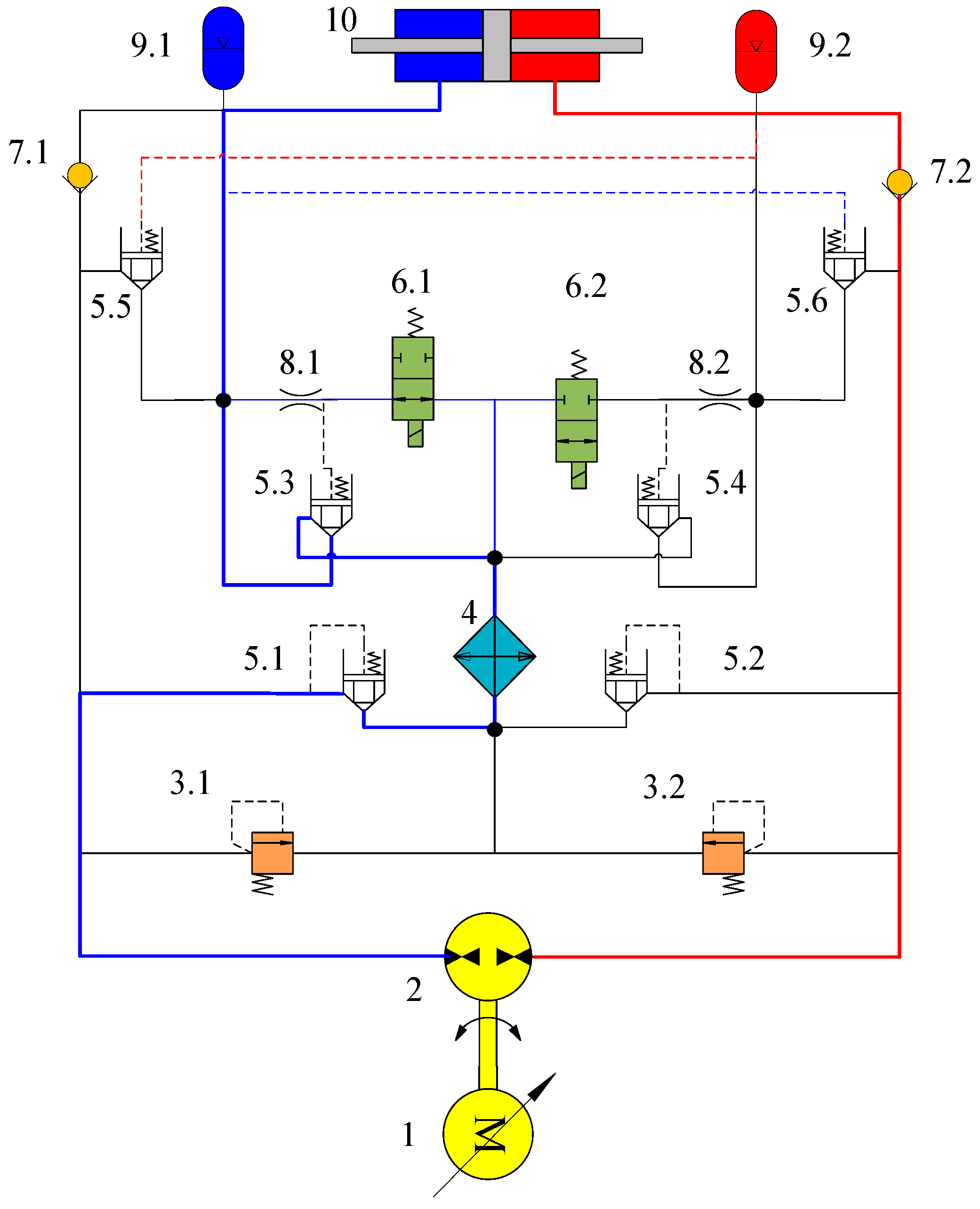
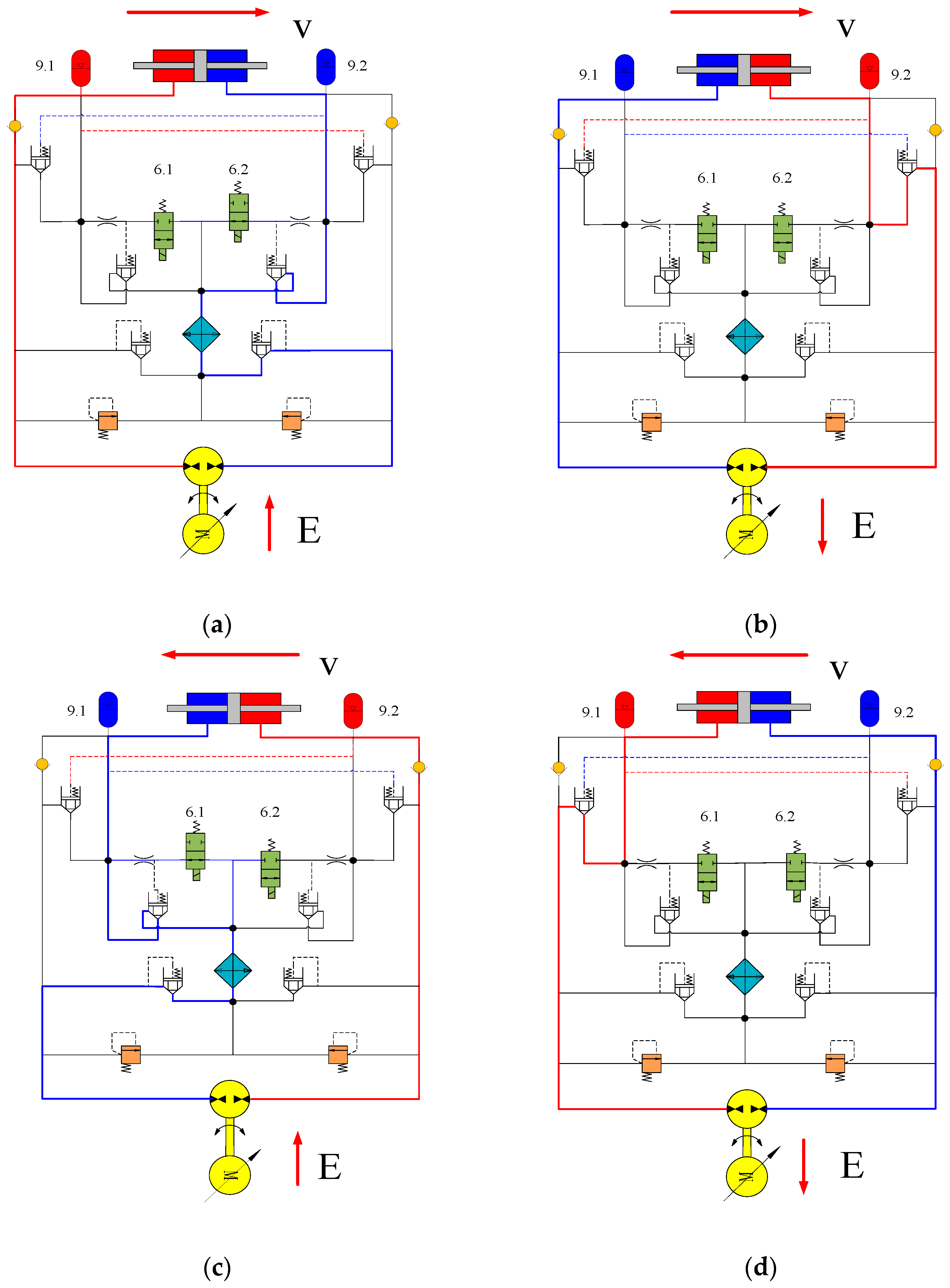
2. Principle of Operation of Pump-Controlled Grinders

The pump-controlled grinder consists of a servo motor, a quantitative pump, a relief valve, a cooler, a two-way cartridge valve, a solenoid valve, a throttle valve, a check valve, an accumulator, and a double-outlet symmetrical cylinder. The servo motor drives the quantitative pump to rotate at variable speed, regulates the system flow, and then controls the system pressure to drive the load to run according to the target motion trajectory. Due to the continuous operation of the pump-controlled grinder, the system oil temperature is high. To reduce the oil temperature, a cooler is installed. The schematic diagram of the pump-controlled grinder is shown in Figure 1.
In Figure 1, the components are numbered as follows: 1. servo motor, 2. quantitative pump, 3. relief valve, 4. cooler, 5. two-way cartridge valve, 6. solenoid valve, 7. check valve, 8. throttle valve, 9. accumulator, 10. double-outlet symmetrical cylinder. When the electromagnetic reversing valves 6.1 and 6.2 are in the position shown in the figure, for the table to perform the leftward feeding motion, the motor drives the pump to produce high-pressure oil through the red path to the right chamber of the hydraulic cylinder 10. Simultaneously, low-pressure oil from the left chamber of the hydraulic cylinder flows through the blue path and the cooler to the low-pressure side of the pump. When 6.1 is closed and 6.2 is opened, the motor drives the pump to provide high-pressure oil to the left side, the oil flow direction is reversed compared to the previous state, and the table makes a feeding motion to the right. The pump-controlled grinder can work in four quadrants. In addition to the above two directions for performing feeding motions, during the braking phase, it can also operate with the pump functioning as a motor, driving the motor to generate electricity, thus achieving energy regeneration. The four-quadrant working process is shown in Figure 2.
In the right feeding stage, when the solenoid valve 6.2 is opened, the motor provides energy to the system, driving the pump to produce high-pressure oil on the left side, which then drives the hydraulic cylinder to move the load to the right. In the rightward braking energy recovery phase, when the solenoid valve 6.2 is closed, the motor stops providing energy to the system. The inertia of the load drives the hydraulic cylinder to continue moving to the right, causing the right side of the hydraulic cylinder to produce high-pressure oil, which drives the pump to function as a motor, enabling the motor to generate electricity for electrical energy recovery. Simultaneously, oil flowing into the right-side accumulator causes pressure to rise, facilitating hydraulic energy recovery. Since passing through the cooler produces energy dissipation, in the energy recovery phase, solenoid valve 6.2 is closed to prevent oil from passing through the cooler. Instead, the oil flows through the two-way cartridge valve directly to the pump, reducing energy loss. The left feeding and left braking energy recovery processes are symmetrical to their right-direction counterparts.
In the rightward braking energy recovery phase, when solenoid valves 6.1 and 6.2 are closed, the table stops after performing damped oscillations. The remaining energy, except that recovered by the motor, is partly dissipated and partly stored in the accumulator. The energy stored in the accumulator 9.1 acts as an obstacle when starting in the left direction, which, together with the dissipated energy, results in poor overall energy utilization. Moreover, the energy stored in the accumulator 9.1 during leftward starting corresponds to an increase in the system load, which can lead to a longer stabilization time to reach the target speed. Therefore, the timing of opening solenoid valve 6.1 and starting the motor significantly affects the energy utilization efficiency of the system and the time required for the commutation to reach steady state.
The pump-controlled grinder has a significant load mass, and energy transfer from the motor to the load requires time, resulting in a lag. During the energy recovery phase, when the load reaches its maximum reverse acceleration, accumulator 9.2 achieves its maximum energy recovery, while accumulator 9.1 reaches its minimum energy level. At this point, the peak phase for motor energy recovery has also passed. Initiating commutation at this time allows the load to move in reverse for a period of time. This provides sufficient time for energy transfer from the motor to the load, maximizes energy recovery, minimizes the negative impact of accumulator 9.1, reduces oscillation-related losses, and shortens the energy transfer process. Starting too early results in insufficient energy recovery, and starting too late creates an additional burden due to the boosting of accumulator 9.1. Therefore, for a pump-controlled grinder with significant load mass and dual-mode energy recovery using an accumulator and motor, it is more appropriate to initiate commutation when the load reaches its maximum reverse acceleration during the energy recovery phase.
Due to the numerous interferences during the operation of the pump-controlled grinder and the rapid changes in acceleration and speed, relying on acceleration or speed indicators to determine the commutation timing can lead to instability. In this study, the maximum recovered energy is introduced as a key parameter, and the commutation control is implemented by predicting the time point of maximum recovered energy. Since the total amount of recovered energy has a cumulative effect and does not change rapidly and drastically due to external disturbances, the robustness of the control strategy can be improved.

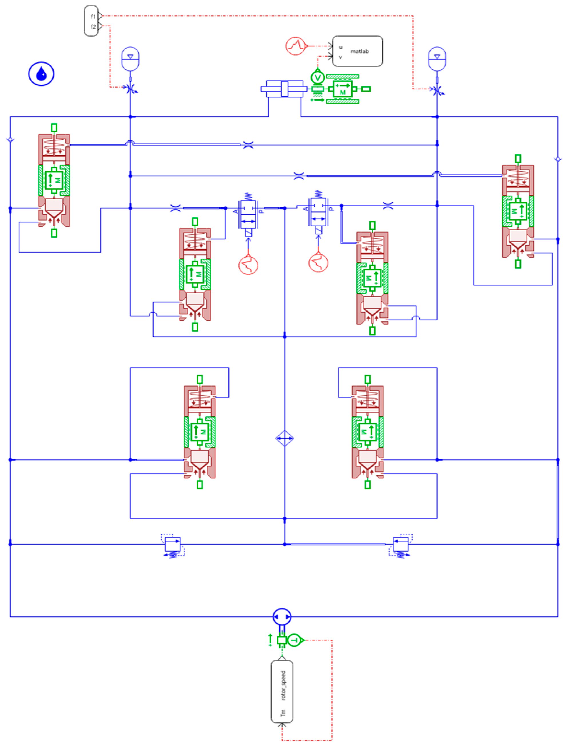
3. Modeling of Energy Recovery Systems for Pump-Controlled Grinders [31,32,33]

The dynamic equation for hydraulic cylinder:
m x ¨ = A P 1 P 2 B v x ˙ F c t a n h x ˙ ϵ F e x t
where:
m is the mass of the table and workpiece;
x ¨ is the piston acceleration;
x ˙ is the piston speed;
P 1 is the hydraulic cylinder left chamber pressure;
P 2 is the hydraulic cylinder right chamber pressure;
A is the effective area of a single chamber of the hydraulic cylinder;
B v is velocity-dependent damping;
F c is the Coulomb friction;
ϵ is the smoothing factor;
F e x t is the external disturbance force.
The hydraulic cylinder flow continuity equations:
Q 1 = A x ˙ + V 1 β e d P 1 d t + C i p P 1 P 2
Q 2 = A x ˙ V 2 β e d P 2 d t C i p P 1 P 2
where:
Q 1 is the flow rate in the left chamber of the hydraulic cylinder;
Q 2 is the flow rate of the right chamber of the hydraulic cylinder;
V 1 is the volume of the left chamber of the hydraulic cylinder;
V 2 is the volume of the right chamber of the hydraulic cylinder;
β e is the bulk modulus of elasticity of the fluid;
C i p is the internal leakage coefficient of the hydraulic cylinder.
Symmetric change in cavity volume:
V 1 = V 01 + A x , V 2 = V 02 A x
where V 01 = V 02 is the initial volume of the two chambers and x is the piston displacement.
Quantitative pump flow equation:
Q p = D p ω m
D p is the pump displacement;
ω m is the pump speed.
The torque equation when the pump is output as a motor condition:
T p   =   Δ P × D p
Δ P is the pressure difference between the two sides of the motor.
Motor dynamics equation:
J d ω m d t = T p B p ω m T e
J is the moment of inertia;
B p is the pump viscous friction coefficient;
T e is the electromagnetic torque.
Accumulator flow equation:
q ( t ) = C d A a 2 ρ P     P a
where:
C d is accumulator mouth flow coefficient;
A a is accumulator mouth area;
ρ is oil density;
P is accumulator port fluid pressure;
P a is accumulator gas pressure.
Assuming that the gas in the accumulator follows a multivariate process and neglecting the heat losses, the accumulator gas equation of state:
P ( t ) V ( t ) n = P 0 V 0 n
P ( t ) is real-time gas pressure;
V ( t ) is the real-time gas volume;
P 0 , V 0 is the initial pre-inflation pressure and volume;
n is the variability index.
Oil volume versus gas volume:
V ( t ) = V 0 Q ( t )
Q ( t ) is the real-time volume of oil in the accumulator:
Q ( t ) = t 0 t q ( t ) d t
Accumulator oil volume change rate:
V a ˙ = q ( t )
The motor outputs power to the outside:
P m ( t )   =   Δ P × Q p
Motor Recovery Power:
P e ( t )   = η g × P m ( t )
η g is the motor power generation efficiency.
The motor recovery energy is:
E e ( t ) = t 0 t P e ( t )   d t
The energy E a ( t ) stored by the accumulator is equal to the work done by the external compressed gas, that is, the integral from the initial volume V 0 to the current volume V ( t ) :
E a ( t ) = V 0 V ( t ) P ( V ) d V
where P ( V ) = P 0 V n V n .
Substitute the pressure expression and integrate:
E a ( t ) = V 0 V ( t ) P 0 V 0 V n d V = P 0 V 0 n V 0 V ( t ) V n d V
The total real-time energy stored in the accumulator is collapsed to obtain the energy equation for the total real-time energy stored in the accumulator:
E a ( t ) = V 0 V ( t ) P ( V ) d V = P 0 V 0 n 1 V 0 V ( t ) n 1 1
Energy recovery process, the total energy recovered = accumulator recovery energy + motor recovery energy:
E ( t ) = E a ( t ) + E e ( t ) = P 0 V 0 n 1 V 0 V ( t ) n 1 1 + η g t 0 t P m ( t ) d t

4. Direction Switching Strategy Based on Energy Peak Time Prediction

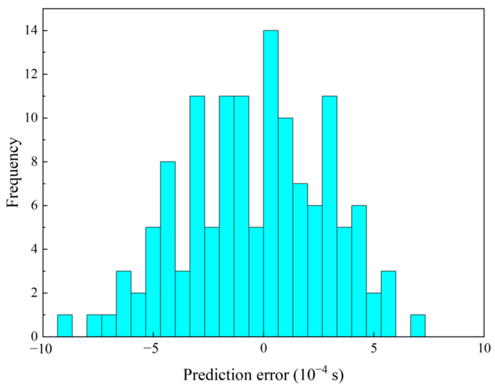
4.1. Prediction of Time to Peak Energy

State prediction of actual complex hydraulic systems usually needs to consider the nonlinear characteristics, dynamic behavior, and various uncertainties of the system, while the actual behavior of the system can be better captured by fitting the test data. In order to generate the recovered energy curves under different parameter conditions, a total of 660 experiments were conducted using the developed model to test different parameter combinations. The load mass was taken from 14,000 kg to 30,500 kg with a step of 1500 kg; the initial speed of the energy recovery phase was 0.45 m/s to 0.55 m/s with a step of 0.01 m/s; and the leakage coefficient of the hydraulic cylinder was 1.81 × 10⁻¹² m3/s/Pa to 2.21 × 10⁻¹² m3/s/Pa with a step of 1 × 10⁻¹³ m3/s/Pa.
The peak time of recovered energy was predicted using five models: Linear Regression (LR), Random Forest (RF), Support Vector Machine (SVM), Gaussian Process Regression (GPR), and NN. Model performance was evaluated based on Root Mean Square Error (RMSE), R2, and Mean Absolute Error (MAE).
The RMSE, R2 and MAE values for the five models are shown in Table 2.
By comparing all performance metrics (RMSE, R2, and MAE) of the models in Table 2, the Neural Network (NN) model demonstrates superior performance across all three indicators (R2 ≈ 0.99997, RMSE = 0.0003256, MAE = 0.0002668); thus, NN is selected for predicting the peak time of recovered energy.
The blue points in Figure 3 indicate the relationship between the actual values and the predicted values for each data sample, and these points are roughly distributed along a straight line, indicating a strong linear relationship between the predicted and actual values. The red dashed line is the fitting line, which indicates the best linear relationship between the predicted and actual values. The data points are closely distributed around the fitting line, indicating that the model has superior predictive performance, with minimal differences between predicted and actual values.
Figure 4 shows that the peak time prediction error of NN ranges from approximately −10−3 s to 10−3 s. The frequency of an error of 0 is the highest, indicating that most prediction errors are close to 0, meaning that the model’s prediction results are very close to the actual values. The graph is roughly symmetrical, suggesting that the error distribution is close to a normal distribution, i.e., the errors are evenly distributed in both positive and negative directions. The errors are mainly concentrated between −0.0005 and 0.0005, indicating that in most cases, the model’s prediction results do not show substantial differences from the actual values. At the two ends of the error range, the frequency is relatively low, indicating that extreme errors occur less frequently. Therefore, the prediction accuracy of NN is high, and its performance is stable.

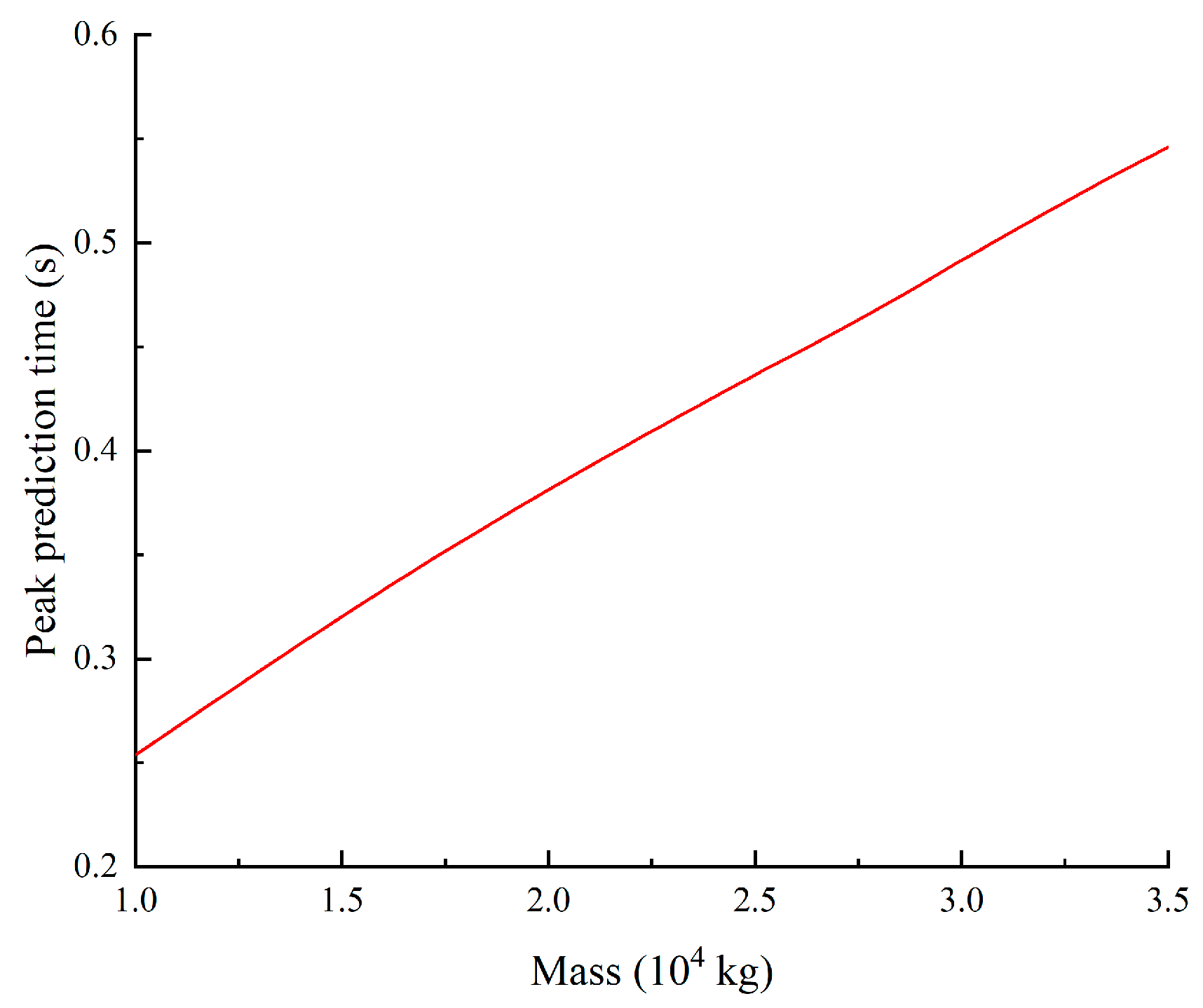
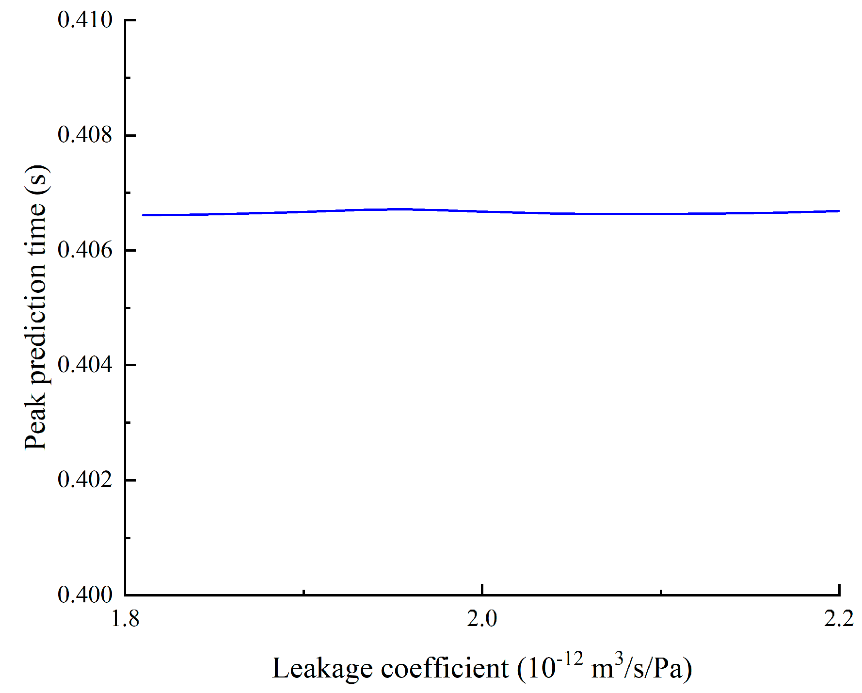
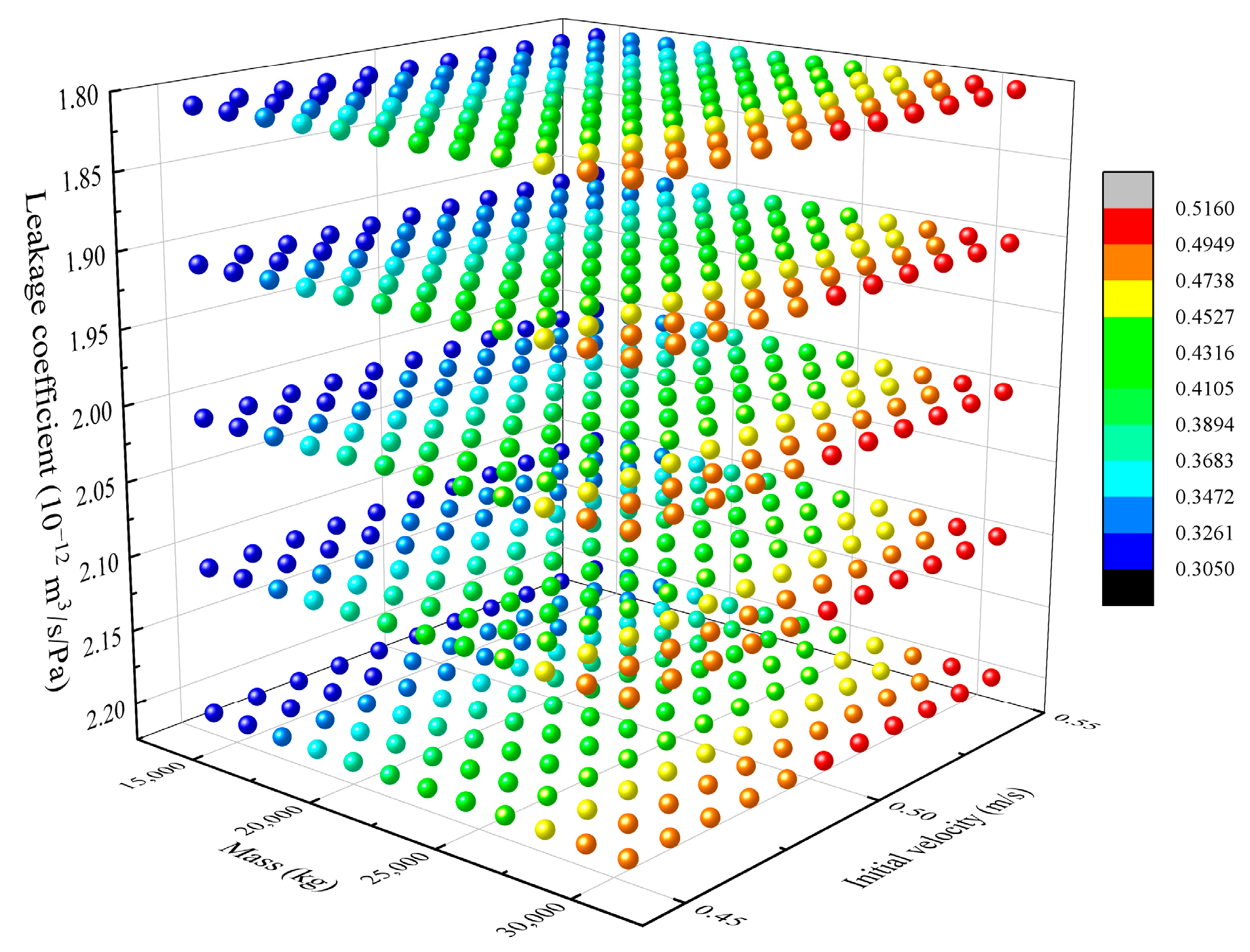
4.2. Parametric Sensitivity Analysis of the Peak Time of Recovered Energy

The parameter sensitivity of the peak time of recovered energy was analyzed to derive the relationship between the effect of mass, initial velocity and hydraulic cylinder leakage coefficient on the peak time of recovered energy.
Figure 5 shows that there is a linear relationship between mass and the prediction peak time of recovered energy, with a corresponding increase in this parameter as mass increases.
Figure 6 shows the relationship between the initial velocity and the prediction peak time of recovered energy. There is a nonlinear relationship between the initial velocity and the predicted peak time of recovered energy. At lower initial velocity, the change in the prediction peak time is relatively small and the curve is relatively smooth. However, when the initial velocity exceeds 0.5 m/s, the predicted peak time begins to increase substantially, and the curve becomes steeper. Within this higher velocity range, the initial velocity has a more pronounced effect on the predicted peak time of recovered energy.
Figure 7 demonstrates the relationship between the leakage coefficient and predicted peak time of recovered energy. Because of the physical constraints of the actual system, the value of the leakage coefficient cannot increase indefinitely within the operational range. In the test, the fluctuation of the leakage coefficient is limited to a narrow range, resulting in a minimal correlation between the leakage coefficient and the predicted peak time. This relationship is so minimal that the change is hardly visible in the figure.
In Figure 8, each point represents a data sample, with colors indicating the predicted peak time of recovered energy. The color bar shows the range from 0.305 s to 0.516 s, transitioning gradually from blue to red. As mass and initial speed increase, the predicted peak time increases correspondingly. The initial speed demonstrates the strongest influence on the predicted peak time, followed by mass, while the leakage coefficient has minimal effect on the predicted peak time.
In actual production, the machining speed and leakage coefficient remain relatively constant, while the load mass varies with the mass of the workpiece being processed. The effect of mass on the predicted peak time of recovered energy is substantial. Therefore, it is necessary to predict the peak time of recovered energy under different parameter conditions.

4.3. Switching Time Decision Strategy

From the statistics of the test data, the earliest predicted peak time of recovered energy was 0.305 s, the latest was 0.515 s, and the average was 0.40575 s, with a standard deviation σ = 0.060157 s.
To improve the system’s operational reliability, the predicted values were calibrated using statistical parameters derived from both test data and current working conditions. The confidence level of these predictions was quantified through a weighted scoring system. Range indicators were designed to assess whether the predicted values conformed to the physical boundaries established by the test data:
W R = 1   if   T pred   0.305,0.515 , 1.8 1 T pred   μ test R test     otherwise .
where T pred   is the prediction time, μ test is the test mean, and R test   is the full range of test values, equal to 0.515–0.305.
If the predicted value is within the range of values taken by the test, W R = 1, it is fully plausible, and if it is outside that range, it is calculated according to the linear decay formula.
A Gaussian probability density function was used to design a statistical metric for assessing the match between predicted values and recent historical data:
W S = e 0.5 T pred   μ hist   σ hist   2
where μ hist   is the historical mean of the current working conditions and σ hist   is the standard deviation of the historical data for the current working conditions.
The exponential decay characteristics ensure that the decay magnitude increases proportionally with greater deviations from the historical mean value of the current operating conditions.
The weights were distributed according to 60% and 40% to form a credibility score formula:
C = 0.6 W R + 0.4 W S
When the scoring formula calculates a confidence value, the predictions are considered highly reliable and are used directly without correction.
When 0.5 C < 0.6 , the correction formula is applied:
T   =   ( T pred   + 0.305 ) / 2   if   T pred   < 0.305 , ( T pred   + 0.515 ) / 2   if   T pred   > 0.515 .
When C < 0.5 , the prediction value is considered to deviate significantly from the theoretical expectation. In this case, the current prediction is abandoned in favor of a conservative estimate. Commutation is triggered at 0.3 s when the predicted value was less than 0.305 s, and at 0.53 s when the predicted value was greater than 0.515 s to ensure system safety.

5. Simulation and Experimental Validation

5.1. Software Simulation Test

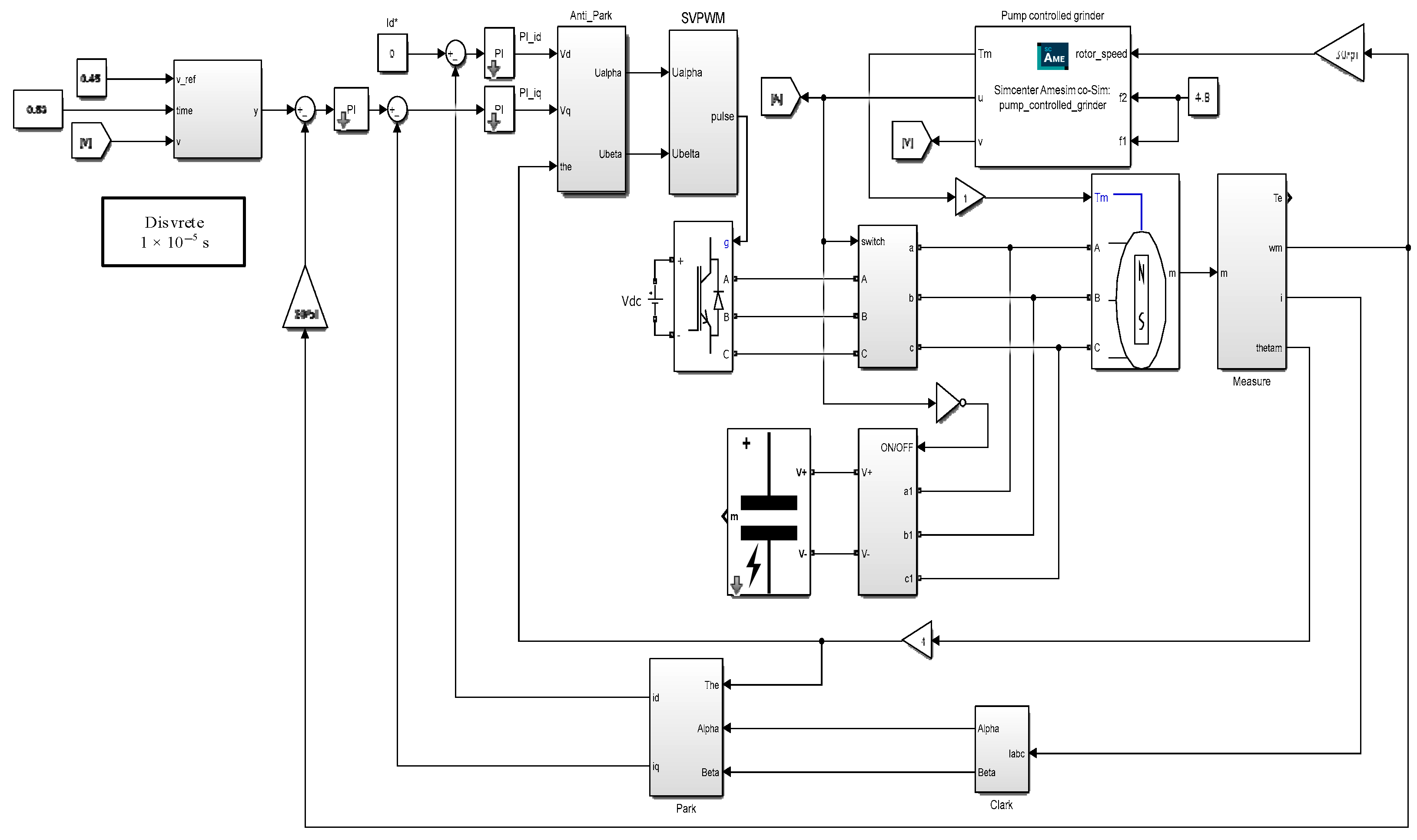
5.1.1. Simulink-Amesim Joint Simulation Platform

Simulation tests were conducted using Simulink (2024b) and Amesim (2404) in a joint simulation approach. Figure 9 shows the Amesim model, while Figure 10 presents the Simulink model.
This platform integrates the advantages of two simulation tools. Simulink is responsible for implementing control algorithms and data processing, while Amesim is used for physical modeling of hydraulic systems. The S-function interface of Amesim is utilized to generate modules compatible with Simulink, and these modules are imported into the Simulink environment. This interface contains all the input/output ports of the hydraulic system, enabling Simulink to directly interact with the Amesim model. A fixed-step solver strategy is adopted for time synchronization. Simulink and Amesim use the same basic time step (0.01 s) to ensure precise data exchange between the two environments. At each time step, Simulink first calculates the control output and then transfers it to Amesim. After performing hydraulic system calculations, Amesim returns the results to Simulink for the next control decision making. A complete variable mapping table is established to ensure correct data conversion between the two environments. The key mappings are as follows: from Simulink to Amesim: motor speed command and accumulator orifice size (set to 4.8 mm); from Amesim to Simulink: pump torque, piston speed, and solenoid valve status signal.
The co-simulation platform performs initialization synchronization at the start of each simulation to ensure consistent system states. During the simulation process, Simulink controls the overall workflow, and the data exchange frequency is equal to the basic time step, ensuring no data loss between the two environments.

5.1.2. Simulation Test

The load mass is 20,000 kg, the initial speed of the energy recovery phase is 0.45 m/s, and the leakage coefficient is 2.01 × 10⁻¹² m3/s/Pa for the energy recovery test. The predicted peak time of energy recovery is 0.38 s after braking. After 4 s of forward motion, braking was initiated. Figure 11 shows the energy recovery effect when the commutation time is taken as 0.5 s.
Figure 11 shows that in the energy recovery process, the peak value of the recovered energy occurs roughly at 4.38 s. If the commutation is performed at 4.5 s, the system cannot achieve the purpose of maximizing the recovered energy, and it prolongs the energy recovery phase. The total energy recovered has a peak value of 972 J. The peak energy recovered by the accumulator is 641 J. The energy recovered by the motor increases with time.
Instead of initiating commutation in the energy recovery phase, the load is allowed to oscillate freely until it stops. The energy recovery effect for this scenario is shown in Figure 12.
Figure 12 shows that without commutation, allowing free oscillation until the system stops, the energy recovered by the motor continues to increase over time. Meanwhile, the energy recovered by the accumulator oscillates with a decreasing trend, causing the overall energy to follow an oscillating pattern. The peak value of the total recovered energy decreases progressively as time increases, until the load eventually stops moving.
Energy recovery can be maximized by accurately predicting the time of peak recovered energy and initiating commutation at the optimal moment.
Figure 13 illustrates the load motion speed profiles when commutation is initiated at two different times: 0.38 s and 0.5 s after the start of the energy recovery phase.
Figure 13 demonstrates that initiating commutation at 0.38 s allows the system to enter steady state faster than when commutation occurs at 0.5 s. Additionally, the steady state speed accuracy is higher with the earlier commutation timing.
The pressure dynamics of the hydraulic system in the energy recovery phase differ significantly between systems with and without an accumulator. Figure 14 illustrates the pressure changes in the right chamber of the hydraulic cylinder during the energy recovery phase for both configurations.
The comparison in Figure 14 between configurations with and without an accumulator clearly demonstrates that the configuration with an accumulator is more effective; with an accumulator, the pressure peak in the hydraulic cylinder chamber during the energy recovery phase is substantially reduced, and the pressure change curve is smoother, avoiding the sharp pressure fluctuations that occur without an accumulator. This improvement provides multiple benefits to the system. First, the lower pressure peak reduces hydraulic shock and decreases the risk of fatigue in pipelines and components; second, the smoother pressure change enhances the stability of system control, facilitating precise speed control; finally, this characteristic also reduces energy loss, indirectly improving energy recovery efficiency. Therefore, installing an accumulator is an effective measure to improve system reliability and energy efficiency.
The load mass is 30,000 kg, the initial speed of the energy recovery phase is 0.45 m/s, and the leakage coefficient is 2.01 × 10⁻¹² m3/s/Pa for the energy recovery test. Two scenarios with misreported mass values were tested to evaluate system robustness.
First scenario: When the mass is misreported as 33,000 kg, the maximum peak time is predicted to be 0.515714 s. According to the credibility calculation system, a credibility value of 0.5896 is obtained. The commutation time decision system identifies the parameter discrepancy and adjusts the commutation timing to 0.5154 s.
Second scenario: When the mass is misreported as 35,000 kg, the maximum peak time is predicted to be 0.532 s, resulting in a confidence value of 0.4748. The commutation time decision-making system determines that there is a significant parameter error and sets the commutation timing to 0.53 s.
The effect of these different commutation timings on motion velocity is illustrated in Figure 15.
Figure 15 demonstrates that the proposed credibility-based decision system effectively compensates for parameter discrepancies, ensuring a smooth transition during commutation even when the input mass values contain errors.

5.2. Bench Test

Figure 16 illustrates the pump-controlled grinder test bench, which includes the main hydraulic components, such as a servo motor, a quantitative pump, an accumulator, a hydraulic cylinder, a make-up motor, and load platform. Additionally, the test bench is equipped with an electrical control cabinet that serves as the core of system control and data processing. The control cabinet contains controllers, servo drives, data acquisition hardware, and safety circuits. The system collects signals such as hydraulic cylinder velocity, motor torque, and hydraulic cylinder pressure in real time to calculate the recovered energy.
The detailed specifications of the test bench components are presented in Table 3. Experiments were conducted using the test bench to validate the proposed commutation strategy. The electric power regenerated by the motor was calculated from voltage and current measurements, and then integrated over time to determine the total electrical energy recovered. The hydraulic energy recovered by the accumulator was calculated based on the measured pressure changes. The total recovered energy represents the sum of both the electrical energy from the motor and the hydraulic energy from the accumulator. Figure 17 illustrates the energy recovery performance under the experimental conditions.
Figure 17 shows that the motor recovers energy relatively quickly during the initial stage, with significantly less energy recovered after 4.05 s. This behavior differs from the simulation results, where the motor’s recovered energy showed a steadily increasing trend. This discrepancy is primarily attributed to energy losses during the actual power generation process. During operation, the motor has mechanical friction losses and electromagnetic losses. Electromagnetic losses mainly include iron loss and copper loss. Iron loss is related to the motor’s frequency and magnetic flux density, while copper loss is proportional to the square of the current. At low speeds, the motor frequency is low, and iron loss is relatively small, but due to the larger current, copper loss is dominant. Coupled with friction losses, this leads to lower power generation efficiency. At high speeds, the frequency increases, and although iron loss increases, the power generation efficiency is higher due to the significant increase in induced electromotive force and generated power. In actual working conditions, the energy recovered by the motor is not directly proportional to the motor speed; the recovery efficiency is higher only in the initial stage of braking and lower during the low-speed oscillation phase. Therefore, predicting the optimal timing for commutation can improve energy recovery efficiency, reduce losses, shorten braking time, and enhance the grinder’s overall operational efficiency. The experimental results also indicate that the energy recovery peak occurs at 0.3 s after braking begins. When commutation is initiated at this optimal time (0.3 s after braking), compared to using a fixed time of 0.4 s, the total recovered energy increases by 100 J, representing a 14.3% improvement in energy recovery efficiency. Furthermore, initiating commutation at 0.4 s causes increased pressure on the opposite side of the hydraulic cylinder, which hinders the commutation process and further reduces energy utilization efficiency. Thus, initiating commutation at 0.3 s delivers an energy recovery efficiency at least 14.3% higher than at 0.4 s. Additionally, the process time is reduced by 0.1 s, representing a 25% improvement in commutation time efficiency.
Figure 18 shows how initiating commutation at different times affects the load motion speed profiles.
Figure 18 demonstrates that initiating commutation at 0.3 s enables the system to enter steady state and reach the target speed faster than when initiating at 0.4 s. This shortened speed adjustment time before grinding operations further improves the pump-controlled grinder’s overall operational efficiency.

6. Conclusions

This research addressed the critical challenge of maximizing energy recovery and ensuring smooth, rapid commutation in pump-controlled grinders with significant inertia characterized by frequent reciprocating motions. A dual-mode synergistic energy recovery system, integrating motor regeneration and hydraulic accumulator storage, was proposed and analyzed. The core contribution is the development and validation of a novel commutation control strategy based on accurately predicting the peak time of recovered energy.
A mathematical model of the pump-controlled grinder with dual-mode recovery was established. Through extensive simulations covering various operating parameters (load mass, initial velocity, leakage), the NN model was identified as the most effective predictor for the peak time of recovered energy, substantially outperforming LR, SVM, GPR, and RF models (NN R2 ≈ 0.99997). Sensitivity analysis revealed that load mass and initial velocity are the dominant factors influencing the peak time of recovered energy.
Based on the NN prediction, an optimal commutation timing strategy was formulated, incorporating a confidence scoring mechanism derived from statistical analysis of test data and recent operational history. This adaptive approach enhances robustness by correcting or defaulting to safe values when predictions fall outside expected ranges or exhibit low confidence, effectively handling parameter uncertainties or errors.
Both simulation (Simulink–Amesim co-simulation) and experimental validation on a 10-ton load test bench confirmed the efficacy of the proposed strategy. Initiating commutation at the predicted peak time of recovered energy maximizes the captured regenerative energy. Experimental results demonstrated a significant improvement, achieving a 14.3% increase in recovered energy and a 25% reduction in commutation time compared to a fixed, slightly delayed commutation strategy. Furthermore, this optimal timing leads to faster settling times to the target velocity and smoother transitions, enhancing overall machine productivity. The study also confirmed the benefit of the accumulator in mitigating pressure shocks within the hydraulic system during the energy recovery phase.
In summary, the proposed dual-mode energy recovery system combined with the peak energy time prediction and adaptive commutation strategy offers a robust and effective solution for improving the energy efficiency, reducing cycle times, and enhancing the operational stability of heavy-duty pump-controlled grinders.
This study conducted experiments and simulations under standard environmental conditions; however, temperature and humidity fluctuations in actual industrial environments may substantially affect system performance. In particular, temperature variations directly influence hydraulic fluid viscosity characteristics, thereby affecting system damping, leakage properties, and energy conversion efficiency. Future research should systematically evaluate system performance under different temperature conditions and develop temperature-adaptive control strategies that compensate for temperature-induced effects through real-time parameter adjustments. The experiments in this study primarily focused on a 10-ton load and medium velocity range. To enhance system robustness in industrial environments, future research will extend to a wider range of testing conditions.

Author Contributions

Conceptualization, B.Y. and G.Y.; methodology, G.C.; software, K.L.; validation, Y.Z. and Y.L.; formal analysis, K.L.; investigation, Y.Z.; data curation, Y.L.; writing—original draft preparation, B.Y.; writing—review and editing, G.Y.; visualization, B.Y.; project administration, K.L.; funding acquisition, G.C. All authors have read and agreed to the published version of the manuscript.

Funding

This research was funded by Hebei Provincial Science and Technology Major Special Project (23281901Z), Key Laboratory of Xinjiang Coal Resources Green Mining, Ministry of Education, Xinjiang Institute of Engineering (KLXGY-Z2402), ‘Tianchi Talent’ Introduction Programme (2024XGYTCYC02), Key Research and Development Program Project of the Autonomous Region (2024B01005-2), Autonomous Region Colleges and Universities Research Program (XJEDU2024P087).

Data Availability Statement

The data presented in this study are available on request from the corresponding author. The data are not publicly available due to no relevant datasets being created.

Conflicts of Interest

The authors declare no conflicts of interest. The funders had no role in the design of the study; in the collection, analyses, or interpretation of data; or in the writing of the manuscript.

Abbreviations

The following abbreviations are used in this manuscript:
GPRGaussian Process Regression
LRLinear Regression
MAEMean Absolute Error
NNNeural Network
RFRandom Forest
RMSERoot Mean Square Error
SVMSupport Vector Machine

References

  1. Liang, T.; Quan, L.; Ge, L.; Xia, L.P.; Wang, C.W. An Energy-Saving Scheme to Reduce Throttling Losses in Hydraulic Excavators Based on Electro-Hydraulic Energy Storage. IEEE Access 2024, 12, 125043–125056. [Google Scholar] [CrossRef]
  2. Xu, L.M.; Wang, K.Z.; Xie, C.L.; Shi, L. Improved spatial acceleration and jerk distributions for grinding force smoothness and energy-saving in reciprocating machining. J. Manuf. Process. 2023, 98, 186–195. [Google Scholar] [CrossRef]
  3. Lyu, L.T.; Chen, Z.; Yao, B. Energy Saving Motion Control of Independent Metering Valves and Pump Combined Hydraulic System. IEEE-ASME Trans. Mechatron. 2019, 24, 1909–1920. [Google Scholar] [CrossRef]
  4. Li, Z.S.; Su, L.; Lin, T.L. Overflow Energy Loss Recovery System Based on Hydraulic Motor-Electric Generator. Appl. Sci. 2021, 11, 941. [Google Scholar] [CrossRef]
  5. Ho, T.H.; Ahn, K.K. Design and control of a closed-loop hydraulic energy-regenerative system. Autom. Constr. 2012, 22, 444–458. [Google Scholar] [CrossRef]
  6. Xing, H.Y.; Zhao, J.Y.; Yin, X.; Ding, H.G.; Meng, X.Z.; Li, J.S.; Wang, G.Y. Simulated research on large-excavator boom based on hydraulic energy recovery. Proc. Inst. Mech. Eng. Part C-J. Eng. Mech. Eng. Sci. 2022, 236, 10690–10700. [Google Scholar] [CrossRef]
  7. Wang, J.L.; Tian, Y.B.; Hu, X.T.; Fan, Z.H.; Han, J.G.; Liu, Y.H. Development of grinding intelligent monitoring and big data-driven decision making expert system towards high efficiency and low energy consumption: Experimental approach. J. Intell. Manuf. 2024, 35, 1013–1035. [Google Scholar] [CrossRef]
  8. Wang, J.L.; Tian, Y.B.; Hu, X.T.; Li, Y.; Zhang, K.; Liu, Y.H. Predictive modelling and Pareto optimization for energy efficient grinding based on aANN-embedded NSGA II algorithm. J. Clean. Prod. 2021, 327, 14. [Google Scholar] [CrossRef]
  9. Guo, Y.S.; Duflou, J.R.; Lauwers, B. Energy-based optimization of the material stock allowance for turning-grinding process sequence. Int. J. Adv. Manuf. Technol. 2014, 75, 503–513. [Google Scholar] [CrossRef]
  10. Hu, L.K.; Zheng, P.; Liu, P.J.; Jia, S.; Cai, W.; Xu, K.K. Energy optimisation for the combination of turning and drilling features using differential evolution. Environ. Sci. Pollut. Res. 2023, 30, 125846–125865. [Google Scholar] [CrossRef]
  11. Wang, H.S.; Zhang, Y.B.; An, Z.S.; Liu, R.S. An Energy-Efficient Adaptive Speed-Regulating Method for Pump-Controlled Motor Hydrostatic Drive Powertrains. Processes 2024, 12, 25. [Google Scholar] [CrossRef]
  12. Wang, H.S.; Zhang, Y.B.; Li, G.Q.; Liu, R.S.; Zhou, X. Design and Control of an Energy-Efficient Speed Regulating Method for Pump-Controlled Motor System under Negative Loads. Machines 2023, 11, 437. [Google Scholar] [CrossRef]
  13. Wu, J.B.; Li, L.; Yan, Y.K.; Wang, P.J.; Wei, W. An Energy-Saving Position Control Strategy for Deep-Sea Valve-Controlled Hydraulic Cylinder Systems. J. Mar. Sci. Eng. 2022, 10, 567. [Google Scholar] [CrossRef]
  14. Hati, S.K.; Mandal, N.P.; Sanyal, D. Energy-saving design of variable-displacement bi-directional pump-controlled electrohydraulic system. Proc. Inst. Mech. Eng. Part I-J. Syst. Control Eng. 2021, 235, 1218–1236. [Google Scholar] [CrossRef]
  15. Li, W.C.; Vaziri, V.; Aphale, S.S.; Dong, S.M.; Wiercigroch, M. Energy saving by reducing motor rating of sucker-rod pump systems. Energy 2021, 228, 13. [Google Scholar] [CrossRef]
  16. Yue, D.L.; Gao, H.F.; Liu, Z.G.; Wei, L.J.; Liu, Y.S.; Zuo, X.K. Potential Energy Recovery and Direct Reuse System of Hydraulic Hybrid Excavators Based on the Digital Pump. Energies 2023, 16, 5229. [Google Scholar] [CrossRef]
  17. Li, J.S.; Han, Y.; Li, S.H. Flywheel-Based Boom Energy Recovery System for Hydraulic Excavators with Load Sensing System. Actuators 2021, 10, 126. [Google Scholar] [CrossRef]
  18. Zhao, P.Y.; Chen, Y.L.; Zhou, H. Simulation Analysis of Potential Energy Recovery System of Hydraulic Hybrid Excavator. Int. J. Precis. Eng. Manuf. 2017, 18, 1575–1589. [Google Scholar] [CrossRef]
  19. Cao, H.L. Kinetic energy recovery and reuse of traveling drive system of hybrid hydraulic electric loader. Adv. Mech. Eng. 2025, 17, 13. [Google Scholar] [CrossRef]
  20. Li, L.; Zhang, T.Z.; Wu, K.W.; Lu, L.Q.; Lin, L.H.; Xu, H.G. Design and Research on Electro-Hydraulic Drive and Energy Recovery System of the Electric Excavator Boom. Energies 2022, 15, 4757. [Google Scholar] [CrossRef]
  21. Ketelsen, S.; Schmidt, L.; Donkov, V.H.; Andersen, T.O. Energy Saving Potential in Knuckle Boom Cranes using a Novel Pump Controlled Cylinder Drive. Model. Identif. Control 2018, 39, 73–89. [Google Scholar] [CrossRef]
  22. Wu, J.J.; Liu, H.; Ren, X.L.; Nie, S.D.; Qin, Y.C.; Han, L.J. A multi-objective optimization approach for regenerative braking control in electric vehicles using MPE-SAC algorithm. Energy 2025, 318, 15. [Google Scholar] [CrossRef]
  23. Jiang, Y.X.; Tong, Z.M.; Tong, S.G.; Xu, Z.Y.; Li, Y.S. Hydraulic dual-module hybrid driving system with adjustable waste energy recovery for industrial vehicles. Energy 2024, 307, 18. [Google Scholar] [CrossRef]
  24. Gong, J.; Zhang, D.Q.; Guo, Y.; Tang, Z.Y.; Liu, C.S.; Hu, P.; Zhao, Y.M.; Quan, W.C.; Jin, Y.P. Potential energy recovery method based on alternate recovery and utilization of multiple hydraulic cylinders. Autom. Constr. 2020, 112, 14. [Google Scholar] [CrossRef]
  25. Li, J.S.; Zhao, J.Y.; Zhang, X.C. A Novel Energy Recovery System Integrating Flywheel and Flow Regeneration for a Hydraulic Excavator Boom System. Energies 2020, 13, 315. [Google Scholar] [CrossRef]
  26. Liu, J.J.; Xu, H.L.; Luo, T.Q.; Yao, Y.F.; Han, W.B. Model-based fault detection for an electrohydraulic braking system with cooperative regenerative braking management. Proc. Inst. Mech. Eng. Part D-J. Automob. Eng. 2025, 22, 09544070251323331. [Google Scholar] [CrossRef]
  27. Mitropoulos-Rundus, C.; Schwarz, C.; McGehee, D. Benefits estimation of regenerative braking versus service braking. Ergonomics 2021, 64, 1217–1227. [Google Scholar] [CrossRef]
  28. Jiang, B.; Zhang, X.W.; Wang, Y.X.; Hu, W.C. Regenerative Braking Control Strategy of Electric Vehicles Based on Braking Stability Requirements. Int. J. Automot. Technol. 2021, 22, 465–473. [Google Scholar] [CrossRef]
  29. Kumar, C.S.N.; Subramanian, S.C. Cooperative control of regenerative braking and friction braking for a hybrid electric vehicle. Proc. Inst. Mech. Eng. Part D-J. Automob. Eng. 2016, 230, 103–116. [Google Scholar] [CrossRef]
  30. Panchal, S.; Dincer, I.; Agelin-Chaab, M. Thermodynamic Analysis of Hydraulic Braking Energy Recovery Systems for a Vehicle. J. Energy Resour. Technol.-Trans. ASME 2016, 138, 9. [Google Scholar] [CrossRef]
  31. Yan, G.; Jin, Z.; Zhang, T.; Zhang, C.; Ai, C.; Chen, G. Exploring the Essence of Servo Pump Control. Processes 2022, 10, 786. [Google Scholar] [CrossRef]
  32. Han, D.; Xin-hui, L.; Xin, W.; Bo-yuan, Z.; Wei-quan, L.; Jia-yi, W. Impact of main parameters of accumulator on parallel hydraulic hybrid. J. Jilin Univ. 2015, 45, 420–428. [Google Scholar] [CrossRef]
  33. Munson, B.R.; Okiishi, T.H.; Huebsch, W.W.; Rothmayer, A.P. Fundamentals of Fluid Mechanics, 7th ed.; John Wiley & Sons, Inc.: Hoboken, NJ, USA, 2013. [Google Scholar]
Figure 1. Working principle diagram of pump-controlled grinder.
Energies 18 02622 g001
Figure 2. Four-quadrant work process of a pump-controlled grinder. (a) Right-hand feed stage. (b) Right-hand brake energy recovery stage. (c) Left feed stage. (d) Left brake energy recovery stage.
Energies 18 02622 g002
Figure 3. Peak time prediction results for NN.
Energies 18 02622 g003
Figure 4. Peak time prediction error distribution for NN.
Energies 18 02622 g004
Figure 5. Relationship between load mass and predicted time to peak recovered energy.
Energies 18 02622 g005
Figure 6. Initial velocity versus predicted time to peak recovered energy.
Energies 18 02622 g006
Figure 7. Leakage coefficients versus predicted time to peak recovered energy.
Energies 18 02622 g007
Figure 8. Combined effect of 3 parameters on peak prediction time.
Energies 18 02622 g008
Figure 9. Amesim model.
Energies 18 02622 g009
Figure 10. Simulink model.
Energies 18 02622 g010
Figure 11. The energy recovery effect when the reversal time is taken as 0.5 s.
Energies 18 02622 g011
Figure 12. Load free oscillation energy recovery effect.
Energies 18 02622 g012
Figure 13. Speed effect with different reverse start times.
Energies 18 02622 g013
Figure 14. Effect of pressure change in the right chamber of the hydraulic cylinder during the energy recovery stage.
Energies 18 02622 g014
Figure 15. The effect of motion velocity in reverse time is obtained with different errors in the parameters.
Energies 18 02622 g015
Figure 16. Pump-controlled grinder test bench.
Energies 18 02622 g016
Figure 17. Energy recovery effect.
Energies 18 02622 g017
Figure 18. Experimental load speed profiles with different commutation timings (0.3 s and 0.4 s).
Energies 18 02622 g018
Table 1. Comparison of energy recovery methods.
Recovery MethodMain Control FeaturesAdvantagesDisadvantagesApplicability to Pump-Controlled Grinding Machines
MotorFour-quadrant operation to convert kinetic energy into electrical energyCan store energy for long periodsLower efficiency at low speedsSuitable for conventional operations; difficult to meet the transient demands of high-frequency dynamic commutation
AccumulatorDirect hydraulic energy storageNo conversion needed, directly stores hydraulic energyLimited by volume and pressure fluctuations; lacks long-term storage capabilitySensitive to pressure fluctuations; limited application in grinding machines with long work cycles
FlywheelConverts hydraulic energy to rotational energyRelatively efficient energy conversionRequires additional mechanical transmissionLimited application in high-frequency commutation grinding due to space requirements and vibration issues
Motor + FlywheelFlywheel handles peak loads; motor handles long-term storageEnhanced dynamic responseSystem complexity increasesMainly applied to engineering machinery rather than precision grinding machines
Motor + AccumulatorIntegrated energy flow managementOptimized energy recovery under various working conditionsRequires precise timing to achieve optimal performanceIdeal for pump-controlled grinding machines with high-frequency commutation; reduces commutation time and improves productivity
Table 2. Performance metrics for the 5 models.
ModelRMSER2MAE
LR0.00286110.997450.0022605
SVM0.00144350.999350.0010713
GPR0.00033020.999960.00026615
RF0.0154030.926040.011819
NN0.00032560.999970.0002668
Table 3. Test bench parameters.
Parameter NameUnitValue
Servo motor rated torqueNm254
Servo motor rated speedr/min1800
Servo motor powerkW48
Hydraulic pump displacementmL/r200
Accumulator volumeL0.5
Accumulator orifice diametermm4.8
Load masst10
Disclaimer/Publisher’s Note: The statements, opinions and data contained in all publications are solely those of the individual author(s) and contributor(s) and not of MDPI and/or the editor(s). MDPI and/or the editor(s) disclaim responsibility for any injury to people or property resulting from any ideas, methods, instructions or products referred to in the content.

