Article

A Fast SOC Balancing Method for MMC-BESS Based on Nonlinear Model-Predictive Control

1
National Institute of Clean-and-Low-Carbon Energy of CHN Energy, Beijing 102209, China
2
CHN Energy Gonghe New Energy Development Co., Ltd., Hainan Tibetan Autonomous Prefecture 813000, China
3
School of Automation and Electronic Engineering, Qingdao University of Science and Technology, Qingdao 266061, China
*
Author to whom correspondence should be addressed.
Energies 2025, 18(10), 2502; https://doi.org/10.3390/en18102502
Submission received: 23 March 2025 / Revised: 22 April 2025 / Accepted: 23 April 2025 / Published: 13 May 2025
(This article belongs to the Special Issue Control and Optimization of Power Converters)

Abstract

:
In modular multilevel converter battery energy storage systems (MMC-BESS), state-of-charge (SOC) balancing is essential for ensuring safe and reliable operation. Existing methods based on linear controllers or conventional model-predictive control (MPC) often suffer from slow balancing speed, difficult parameter tuning, and high computational burden. To address these challenges, this paper proposes a fast SOC balancing strategy based on nonlinear MPC. A nonlinear state-space model is first developed and then linearized to enable discrete single-step prediction of arm- and phase-level SOC values. A two-stage control scheme is introduced to coordinate inter-arm and inter-phase SOC balancing, significantly reducing the number of state variables involved in the MPC formulation. The proposed method eliminates the need for circulating current reference calculation and control parameter tuning. Simulation results demonstrate that the proposed method takes approximately 17.5 s and 39 s for inter-arm and inter-phase SOC balancing, respectively, while traditional three-level SOC balancing takes approximately 42 s and 88 s.

1. Introduction

The intermittency and volatility of renewable energy pose significant challenges to power system stability at scale [1,2]. Battery energy storage systems effectively mitigate power fluctuations from renewable sources, making the integration of BESSs with renewable generation essential. Among various converter topologies, the modular multilevel converter-based battery energy storage system (MMC-BESS) stands out as a promising solution for large-capacity storage due to its unique advantages [3,4]. The MMC-BESS distributes batteries across submodules, which prevents the ‘bucket effect’ and eliminates parallel circulating currents commonly found in traditional battery arrays with extensive series-parallel connections. However, balancing the State of Charge (SOC) of submodule batteries is critical for safe and reliable MMC-BESS operation [5,6].
Research on SOC-balancing control for MMC-BESS has advanced considerably. Reference [7] introduced a traditional three-level control scheme, but its open-loop structure and reliance on proportional components resulted in slower SOC balancing. References [8,9] implemented independent PI controllers for each submodule storage system, enhancing SOC-balancing performance while simultaneously increasing system complexity and complicating parameter tuning. References [10,11] developed a three-level SOC-balancing strategy by combining PI controller, PR controller, and modulation wave reconstruction techniques, though the carrier phase shift modulation method employed exhibits limited applicability in high-voltage, high-power scenarios. Furthermore, conventional PI/PR controllers are highly dependent on parameter tuning, directly affecting system dynamic response and stability, while demonstrating poor adaptability to system nonlinearities and time-varying parameters [12].
Model-predictive control (MPC) enables real-time management of complex systems through dynamic prediction and cost function optimization, effectively eliminating control-parameter-tuning challenges [13,14]. Recent years have witnessed notable progress in MPC strategies for MMC-BESS systems. Reference [15] introduces a modulation-based MPC approach that directly computes duty cycles between two predefined voltage levels, eliminating weighting factors while preserving constant switching frequency. References [16,17] develop a switching state selection MPC method, where combinatorial complexity remains challenging ( C 2 N N valid states) despite limiting active submodules to N per phase. Several enhanced MPC variants address specific challenges: Reference [18] achieves superior current quality by expanding voltage levels from N + 1 to 2N + 1 with minimal computational overhead. For SOC balancing, Reference [19] employs a dual-mode strategy using fixed circulating currents for large imbalances and adaptive coefficients for minor corrections, albeit with increased switching losses. Reference [20] implements a precision dual-loop architecture combining SOC prediction with MPC current tracking, though requiring exact parameter matching.
Advanced control architectures include Reference [21]’s computationally demanding but effective dual-layer solution for low-frequency operation and [22]’s hierarchical approach separating global MPC balancing from local virtual resistance control, offering speed–accuracy compromises. Reference [23] further refines balancing through a three-level algorithm with dynamic coefficients, enhancing stability at the cost of control complexity. Finally, Reference [24] presents an adaptive-weight MPC that dynamically adjusts cost functions based on submodule voltages for optimized MMC performance. Reference [25] proposed a hybrid approach using MPC for output current and circulating current control at the submodule level while still relying on PI control for battery-side SOC balancing, failing to achieve direct MPC over SOC equilibrium. References [26,27] employed traditional double-loop PI control for output currents while incorporating MPC for SOC balancing, indirectly achieving SOC balancing through circulating-current-cost functions but lacking direct control over SOC. References [25,28] introduced an MPC methodology for MMC-embedded storage systems that successfully balanced storage submodule SOC and suppressed current ripple, though this approach is limited to storage submodules with supplementary DC-DC converters and cannot be extended to conventional half bridge energy storage submodules. Also, the cost function is developed based on the current of the energy storage unit. Reference [29] presented an enhanced inner- and outer-loop MPC strategy for output-current control, double-loop PI control for DC/DC converters within storage submodules, and improved inner–outer-loop MPC for SOC balancing. While this method demonstrated effective SOC balancing, it still required PR controllers to calculate circulating-current reference values, maintaining dependency on control parameter tuning.
The existing SOC-balancing control methods for MMC-BESS can be summarized in Table 1. It is evident that the current MPC method for SOC balancing has two significant limitations. First, the predictive model and cost function are based on current rather than SOC, which indirectly reflects SOC characteristics. Second, MPC must be combined with PI/PR control because the current reference required for the cost function needs to be calculated. It can be seen from the above that existing MPC research focused on SOC balancing in MMC-BESS primarily addresses storage submodules equipped with DC-DC converters, while comparatively limited attention has been given to MPC for SOC balancing in traditional half-bridge storage submodules. Most approaches indirectly achieve SOC balancing by minimizing circulating current reference value cost functions, necessitating parameter tuning for proportional, PI, or PR control components. Additionally, these control methodologies share an inherent limitation where balancing speed diminishes as SOC deviation decreases.
To address these challenges, this paper proposes an advanced SOC-rapid-balancing technology for MMC-BESSs based on nonlinear MPC. Key innovations include the following: first, establishing a nonlinear state-space model for average SOC values between upper and lower arms and developing a single-step prediction model with deviation cost function for arm and phase average SOC values through linearization and discretization; second, optimizing control stage division and state variable configuration within the overall MPC scheme to substantially reduce the computational burden. The proposed control strategy offers several advantages: complete SOC control without calculating the circulating current; elimination of traditional control-parameter-tuning requirements; and maintenance of consistent SOC-balancing speed regardless of the SOC deviation magnitude.

2. MMC-BESS Topology and Its Traditional Three-Level SOC-Balancing Control

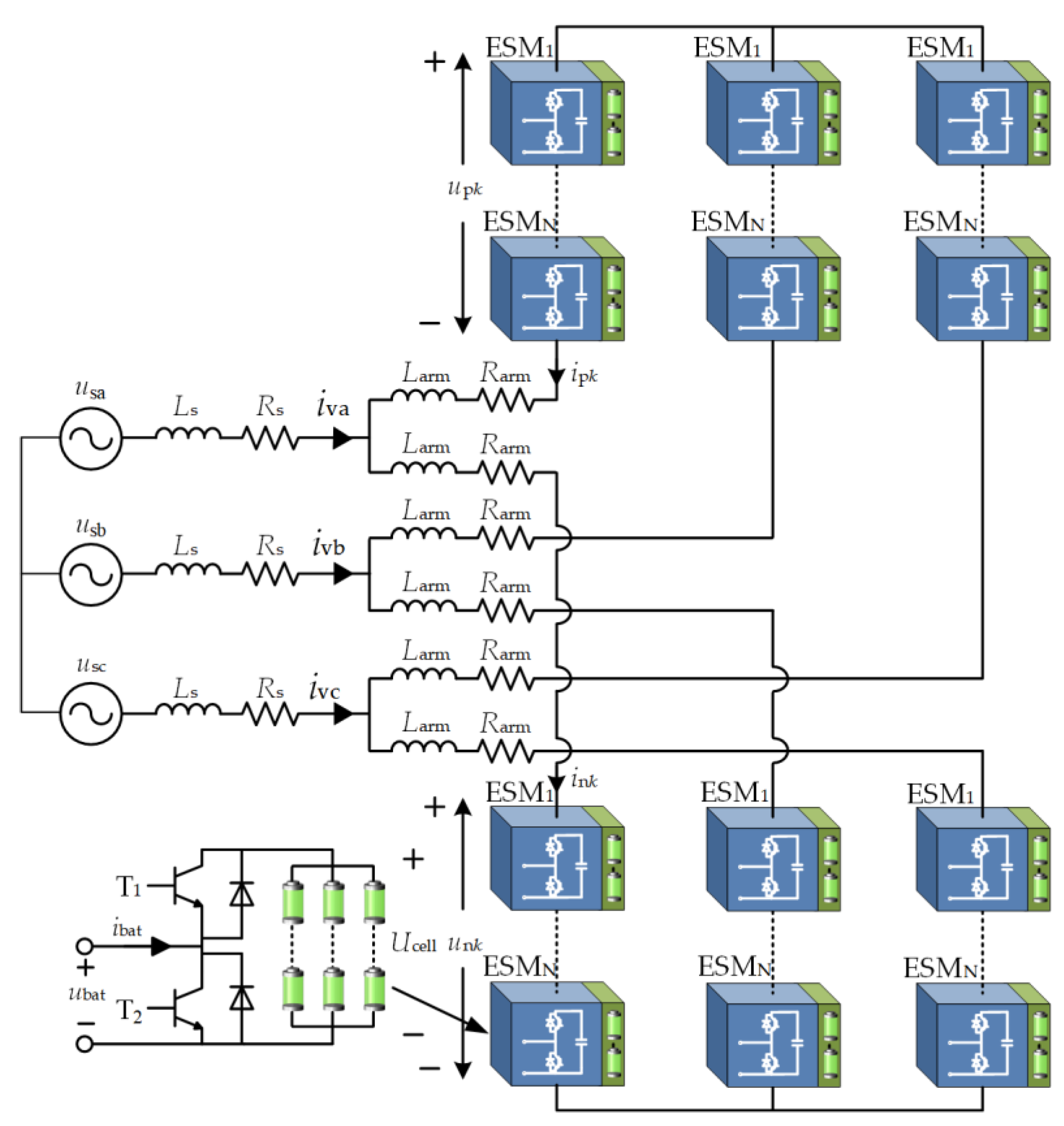
2.1. Topological Structure

The topology of the MMC-BESS and its Energy Submodule (ESM) is shown in Figure 1. Each phase consists of the upper and lower arms. Each arm includes an inductor Larm, an equivalent resistor Rarm, and N ESMs. The parameters are as follows:
Grid-side parameters: usk (k = a, b, c) represents the three-phase grid voltage; Ls and Rs are the equivalent inductance and resistance between the MMC and the grid.
MMC parameters: uk (k = a, b, c) represents the output AC voltage of the MMC; ivk (k = a, b, c) represents the output AC current of the MMC.
Arm electrical parameters: upk and unk (k = a, b, c), respectively, represent the output voltage of the upper and lower arms of phase-k; ipk and ink, respectively, represent the current of the upper and lower arms of phase k.
ESM parameters: The half-bridge topology is adopted, consisting of two IGBTs and one battery pack, where Ucell is the battery pack voltage; ubat and ibat are the output voltage and current of the ESM, respectively.

2.2. Model-Predictive Control of Output Current

The MPC algorithm predicts the single-step output current of MMC-BESS, as shown in Equation (1):
i v k t + T s = 1 R eq + L eq / T s u k t + T s u s k t + T s + L eq T s i v k t
where ivk(t + Ts) and ivk(t) are the predicted value and measured value of the output current of the phase-k, respectively; uk(t + Ts) is the predicted value of the AC-side voltage of the kth phase of MMC; usk(t + Ts) is the predicted value of the grid voltage; Leq and Req are the equivalent inductance and resistance of the AC side, respectively, with Leq = Ls + Larm/2, Req = Rs + Rarm/2; Ts is the simulation time step.
The cost function of output current is as follows:
J i v k = i v k t + T s i v k t + T s
where ivk∗(t + Ts) is the reference value of the output current.

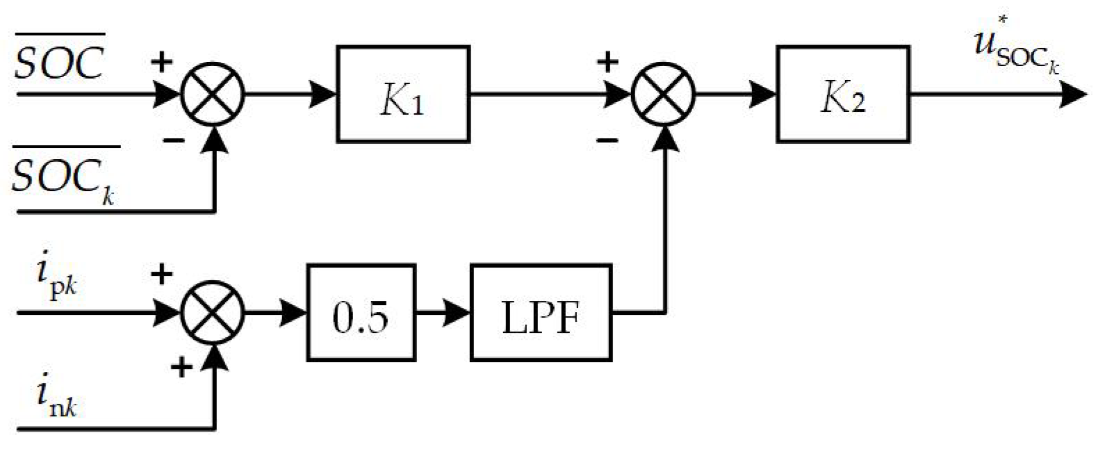
2.3. Traditional SOC-Balancing Control

Traditional SOC-balancing control employs a three-level hierarchical architecture that encompasses inter-phase SOC balancing, inter-arm SOC balancing, and submodule SOC balancing within each arm. An open-loop sorting strategy is typically implemented to minimize controller complexity. The process follows a systematic approach, outlined as follows:
(1)
Calculate the required number of submodules (n*) that need to be activated;
(2)
Sort all submodules within the arm according to their estimated SOC values;
(3)
Apply a current-direction-based selection algorithm: when the arm current causes the battery to discharge, the n submodules with the highest SOC values are activated; when it causes charging, those with the lowest SOC values are prioritized.
The SOC value estimation of the submodule utilizes the Coulomb counting method [30], with the specific calculation methodology detailed in Equation (3):
S O C t = S O C t 0 1 3600 Q max t 0 t i bat t d t
where Qmax represents the battery capacity.
The block diagram of inter-arm SOC-balancing control is presented in Figure 2. Here, SOC ¯ p k and SOC ¯ n k represent the average SOC values of the upper and lower arms of phase k, respectively; K3 is the gain coefficient; and u SOC a r m k * can be obtained, which is the reference voltage for achieving SOC balancing between arms.
The block diagram of inter-phase SOC-balancing control is presented in Figure 3. Here, SOC ¯ k represents the average SOC value of phase-k, SOC ¯ stands for average SOC value of all submodules in the three phases, K1 and K2 are gain coefficients, and LPF refers to a low-pass filter. Finally, u SOC k * can be obtained, which is the reference voltage value for achieving the inter-phase SOC balancing.

3. Nonlinear State-Space Model and Its Linearization

The traditional three-level SOC-balancing control for MMC-BESS has inherent deficiencies, such as slow balancing speed and difficult parameter tuning. To overcome these technical challenges, this paper proposes an SOC-balancing control strategy based on nonlinear model-predictive control, aimed at achieving fast and precise SOC balancing. The following section first establishes a nonlinear state space model for the MMC-BESS system.
This strategy significantly reduces computational burden by decreasing the number of MPC state variables, eliminates the need for calculating arm circulating current references, and achieves fast SOC balancing by only requiring the setting of maximum submodule numbers.

3.1. Nonlinear State-Space Model of MMC-BESS

As shown in Equations (4) and (5), construct the differential dynamic equations of the upper and lower arms.
L arm d i p k d t + R arm i p k + u p k = 1 2 U DC u k
L arm d i n k d t + R arm i n k + u n k = u k 1 2 U DC
where UDC represents the DC-side voltage of MMC-BESS.
Subtracting Equation (5) from Equation (4) yields the dynamic equation governing the MMC output current. This fundamental relationship enables the development of output-current MPC, as formulated in Equations (1) and (2), which will not be discussed in further detail at this juncture.
When Equations (4) and (5) are summed, the differential dynamic equation can be obtained to characterize the arm circulating current:
2 L arm d i c i r k d t + R arm i c i r k + u p k + u n k = U DC
where icirk represents the circulating current of phase k, calculated as icirk = 0.5 × (ipk + ink). The values of upk and unk depend on the number of submodules activated in the upper and lower arms, as shown below:
u p k = N n 1 k * + n 2 k * U c p k ¯
u n k = n 1 k * + n 2 k * U c n k ¯
where N denotes the total number of submodules within each arm; n 1 k * and n 2 k * represent the reference quantity of submodule activation required by output current MPC and inter-arm SOC-balancing control, respectively; U c p k ¯ and U c n k ¯ correspond to the average voltage values across all submodules in the upper and lower arms of phase k, respectively, and must satisfy the conditions U c p k ¯   =   3   +   1.2 SOC ¯ p k , U c n k ¯   =   3   +   1.2 SOC ¯ n k [5]. It should be noted that the relationship between SOC and the voltage of the battery is nonlinear due to many factors, such as battery material, temperature, etc. In engineering applications, it is necessary to first measure the SOC characteristics of the batteries and fit their nonlinear expressions. Here, the SOC characteristic is simplified to linear expression for analyzing easily. It is important to note that while n 1 k * 0 , n 2 k * can be negative values, indicating the flexibility to increase or decrease the number of activated submodules relative to the baseline established by n 1 k * .
Substituting Equations (7) and (8) into Equation (6), the differential dynamic equation of the phase-k arm circulating current can be obtained.
2 L arm d i c i r k d t = U DC 2 R arm i c i r k 1.2 N n 1 k * + n 2 k * S O C ¯ p k + 1.2 n 1 k * + n 2 k * S O C ¯ n k 3 N + 2 n 2 k *
Taking the upper arm of phase-k as an example, assume that the number of submodules put into operation at time t is ( N n 1 k * + n 2 k * ) , then it can be obtained that
Q max d i = 1 N S O C p k i d t = N n 1 k * + n 2 k * i p k
Due to
1 N i = 1 N S O C p k i = S O C ¯ p k
Substitute Equation (11) into Equation (10), and considering that ipk = icirk − 0.5ivk at the same time, this yields
Q max d S O C ¯ p k d t = N n 1 k * + n 2 k * N ( i c i r k 0.5 i v k )
Equation (12) indicates that the average SOC dynamics are primarily governed by three factors: the number of activated submodules, the arm-circulating current, and the output current. Considering that the output current can accurately track its reference value (i.e., ivk = i*vk), to simplify the design of the nonlinear MPC controller, Equation (12) can be rewritten as follows:
Q max d S O C ¯ p k d t = N n 1 k * + n 2 k * N ( i c i r k 0.5 i v k * )
Equation (13) demonstrates that, after the aforementioned simplification, the dynamic characteristics of the arm’s average SOC have been completely decoupled from the output current. Following the same derivation process, the dynamic equation for the lower arm’s average SOC can be expressed as in Equation (14):
Q max d S O C ¯ n k d t = n 1 k * + n 2 k * N ( i c i r k + 0.5 i v k * )
In summary, Equations (9), (13) and (14) constitute the state space model for the average SOC values of the upper and lower arms. Next, we will proceed with the linearization of this state space model.

3.2. Linearization Processing of State-Space Model

Based on the analysis of Equations (9), (13) and (14), it is evident that in the MMC-BESS, there exists a complex coupling relationship between the control variable n 1 k * and n 2 k * for output current and SOC balancing, and the state variables icirk, SOC ¯ p k , and SOC ¯ n k This results in significant nonlinear characteristics in the state-space model of the average SOC values for the upper and lower arms. Therefore, it is not possible to perform single-step prediction directly based on the discretized differential dynamic equations.
To effectively predict the state of the MMC-BESS, it is necessary to linearize the nonlinear state-space model of the system at each control cycle [31]. The specific linearization process first requires reconstructing Equations (9), (13) and (14) into a standard nonlinear state space model form:
x ˙ = f x , u
where x = [icirk, SOC ¯ p k , SOC ¯ p k ]T, u = [ n 2 k * ].
It is worth noting that, due to the previous decoupling of the arm SOC dynamics from the output current dynamics, there is no need to treat n 1 k * as an input variable in this model. In practice, it can be viewed as a time-varying system parameter that always can be treated as a constant.
By applying Taylor expansion to Equation (15) at the operating point (x0, u0) at time t and neglecting the higher order terms beyond second order, the following can be obtained:
Δ x ˙ = f x x 0 Δ x + f u u 0 Δ u = A Δ x + B Δ u
where Δx = xx0, and Δu = uu0. Let A be the system matrix and B be the input matrix. By substituting Equations (9), (13) and (14) into Equation (16), the following can be obtained:
A = R arm L arm 0.6 n 1 k * n 2 k * N L arm 0.6 n 1 k * + n 2 k * L arm N n 1 k * + n 2 k * N Q max 0 0 n 1 k * + n 2 k * N Q max 0 0
B = 3 0.6 S O C ¯ p k + 0.6 S O C ¯ n k L arm i c i r k 0.5 i v k * N Q max i c i r k + 0.5 i v k * N Q max
Equations (16) and (18) represent the linearized state space model of the arm’s average SOC at time t0. Similarly to the output-current MPC, we apply the forward Euler method [32] to approximate the discretization of this model. The discretized expression is shown in Equation (19):
Δ x t + T s = T s A + I Δ x t + T s B Δ u t + T s
It should be noted that at time t, when the system is linearized at the operating point and has not been disturbed by changes in input variables, Δx(t) = 0. Therefore, Equation (19) can be simplified to the following:
Δ x t + T s = T s B Δ u t + T s
Due to
x t + T s = x t + Δ x t + T s
Based on Equations (20) and (21), single-step prediction of the target variables that need to be controlled can be performed, which subsequently facilitates the design of the cost function.

4. SOC-Balancing Control Strategy Based on Model-Predictive Control

4.1. MPC for Inter-Arm SOC Balancing

Based on Equations (20) and (21), the SOC-balancing controller between the upper and lower arms is first constructed. Single-step predictions of average SOC values for upper and lower arms of phase k are performed separately. The prediction equations are shown in Equations (22) and (23):
S O C ¯ p k t + T s = T s i c i r k t 0.5 i v k * t N Q max n 2 k * t + T s n 2 k * t + S O C ¯ p k t
S O C ¯ n k t + T s = T s i c i r k t + 0.5 i v k * t N Q max n 2 k * t + T s n 2 k * t + S O C ¯ n k t
The cost function of the inter-arm SOC balancing can be designed as follows:
J SOC_arm = S O C ¯ p k t + T s S O C ¯ n k t + T s
Considering the computational efficiency requirements for practical controller applications, this paper retains the sorting-control method described in Section 2.3 for SOC-balancing control among submodules within each arm. This design strategy significantly reduces the number of switching state combinations that need to be considered, thereby effectively simplifying the complexity of the model-predictive controller design and making it more suitable for practical simulation verification and hardware implementation.

4.2. MPC for Inter-Phase SOC Balancing

For inter-phase SOC-balancing control, by adding Equations (22) and (23), the single-step prediction value of the average SOC for a phase can be obtained as follows:
S O C ¯ k t + T s = 0.5 S O C ¯ p k t + T s + S O C ¯ n k t + T s = T s i c i r k t N Q max n 2 k * t + T s n 2 k * t + S O C ¯ k t
The average value of the three phase SOC can be expressed as follows:
S O C ¯ t + T s = S O C ¯ a t + T s + S O C ¯ b t + T s + S O C ¯ c t + T s 3
For the inter-phase SOC balance control, its cost function can be designed as follows:
J SOC_pha = S O C ¯ t + T s S O C ¯ a t + T s + S O C ¯ t + T s S O C ¯ b t + T s + S O C ¯ t + T s S O C ¯ c t + T s

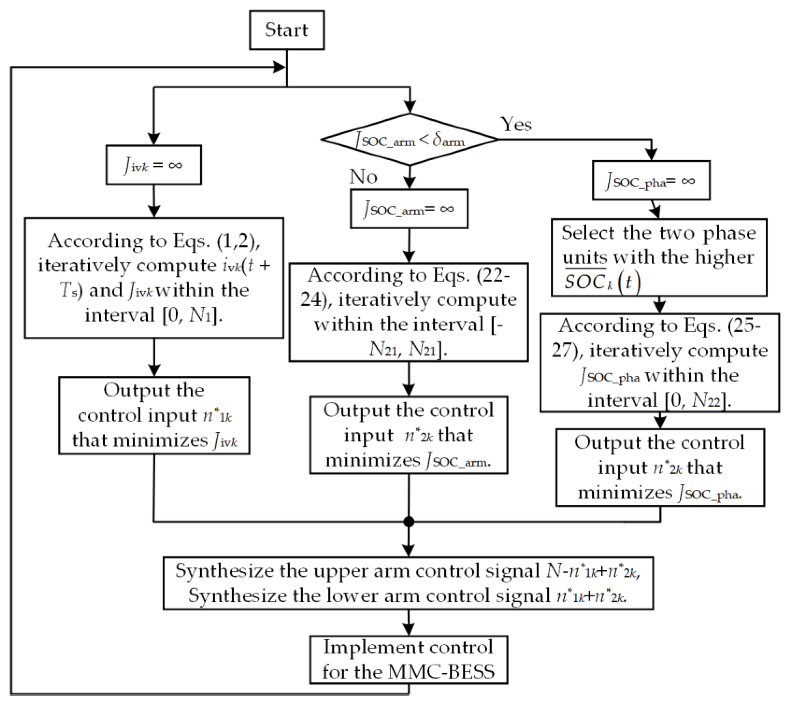
4.3. MPC Scheme Design Considering Inter-Arm and Inter-Phase SOC Balancing

By integrating the strategies proposed in Section 2.2, Section 4.1 and Section 4.2, an overall MPC strategy for MMC-BESS that considers both inter-arm and inter-phase SOC balancing can be constructed. Based on the different number of control states, this paper proposes two design schemes.
(1)
Design Scheme One: Unified Control Approach
This scheme adopts a unified cost function to simultaneously achieve both inter-arm and inter-phase SOC-balancing control. Specifically, n 2 k * is obtained by optimizing the cost function and then added to the n 1 k * to determine the number of submodules to be inserted in the upper and lower arms of each phase. Combining Equations (24) and (27), the unified SOC-balancing cost function can be expressed as follows:
J SOC = λ 1 J SOC_arm + λ 2 J SOC_pha
where λ1 and λ2 are the weighting coefficients for inter-arm and inter-phase SOC balancing, respectively.
This scheme enables simultaneous inter-arm and inter-phase SOC balancing between arms and phases, with the flexibility to control the balancing speed at different levels by adjusting the weighting coefficients. However, this design scheme also presents significant computational burden issues. The specific analysis is as follows:
Assume the maximum number of submodules for output current control and SOC balancing are N1 and N2, respectively, with N1 + N2 = N, then n 2 k * must satisfy the following:
N 2 n 2 k * N 2 ,   n 2 k * N +
From Equation (29), it can be seen that n 2 k * includes (2N2 + 1) state variables. When calculating the cost function in Equation (27), nested loops through n 2 k * of all three phases are required, resulting in (2N2 + 1)3 states to be processed at each control step. The prediction of average SOC values for upper and lower arms and phase units must be calculated at each step. When a faster SOC balancing speed is required, a larger value of N2 causes the number of states to grow exponentially as a cubic function, imposing a significant computational burden.
(2)
Design Scheme Two: Staged Control Approach
To reduce the computational complexity of the MPC, this paper proposes a staged control design scheme. This approach implements inter-arm and inter-phase SOC balancing separately, with the following control strategy: The system prioritizes SOC-balancing control between the upper and lower arms of each phase. When S O C p k   ¯   S O C n k ¯ is detected to be less than a preset error threshold δarm, the controller automatically switches to inter-phase SOC-balancing mode, while temporarily suspending inter-arm SOC balancing. If S O C p k   ¯ S O C n k ¯ subsequently exceeds the preset error threshold δarm, inter-arm SOC-balancing control is reactivated.
In this scheme, the maximum number of submodules for upper- and lower-arm SOC balancing and inter-phase SOC balancing is set as N21 and N22, respectively, with N21 + N22 = N2. According to the analysis in Equation (24), the number of states to consider for inter-arm SOC-balancing control is 2N21 + 1, and the three phases can be computed in parallel without nested loops; inter-phase SOC-balancing control considers (2N22 + 1)3 states. Compared to the first scheme, this design significantly reduces the number of switching states.
Further analysis shows that the number of states for inter-phase SOC-balancing control can be further optimized. This is because inter-phase SOC balancing is essentially achieved by adjusting the DC component of the circulating current in each phase arm. When additional submodules are simultaneously inserted in both the upper and lower arms of a phase, the DC-side voltage of that phase momentarily increases relative to the other two phases, causing the incremental circulating current to accelerate the discharge process of the ESM, thereby reducing the average SOC value of that phase.
Based on this analysis, in inter-phase SOC-balancing control, it is only necessary to insert additional submodules in the two phases with higher average SOC values, while the phase with the lowest SOC average does not require extra control, to achieve convergence of the three phase SOC averages. This optimization means that the two phases with higher SOC only need to consider the number of additional submodules to be inserted, without considering removal operations, while the phase with the lowest SOC requires no additional control. Therefore, the number of switching states for inter-phase SOC-balancing control can be further reduced to (N22 + 1)2.
Through in depth analysis of the control performance of the two design schemes, research has found that the second design scheme offers significant computational efficiency advantages, reducing the computational complexity from cubic exponential to square exponential, effectively alleviating the computational burden on the controller. Although this scheme has certain limitations in terms of the utilization efficiency of submodule regulation capability and requires additional optimization of the N21 and N22 parameters, considering the key requirements of the system’s actual operational performance, especially the important impact of computational burden on the control system, this paper ultimately chooses to adopt this staged control strategy as the overall MPC scheme for SOC balancing in MMC-BESS. The specific implementation process of this control scheme is shown in Figure 4.
As shown in Figure 4, the stage control scheme consists of two parts: MPC for output current and MPC for SOC balancing. These two components operate in parallel without interfering with each other. The output current MPC can be divided into three steps:
Step 1: Initialize J_ivk as infinity.
Step 2: Iteratively compute ivk(t + Ts) and J_ivk within the interval [0, N1] based on Equations (1) and (2).
Step 3: Obtain the control input n*1k that minimizes J_ivk.
Similarly, the SOC balancing MPC can also be divided into three steps:
Step 1: Initially, perform a conditional judgment of JSOC_arm. If JSOC_arm is not less than δarm, the inter-arm SOC is not considered balanced, and JSOC_arm is continuously updated through a simple for-loop over [−N21, N21] according to Equations (22)–(24) until the control input n*2k that minimizes JSOC_arm is found and JSOC_arm < δarm.
Step 2: If JSOC_arm < δarm, the inter-arm SOC is balanced. Then, the two phases with higher average SOCk are selected to insert additional sub-modules. JSOC_pha is continuously updated through double for-loops over [0, N22] according to Equations (25)–(27) to find the control input n*2k that minimizes JSOC_pha.
Step 3: The upper and lower arm control signals (N − n*1k + n*2k) and (n*1k + n*2k) are obtained, respectively. It should be noted that the control modes for inter-arm and inter-phase SOC balancing dynamically switch during the operation of the MMC-BESS to ensure stable operation.

5. Simulation Verification

5.1. Simulation Parameters

To verify the effectiveness of the proposed overall MPC strategy and demonstrate its advantages over traditional SOC-balancing control methods, this section builds a complete MMC-BESS system simulation model based on the MATLAB(R2022b)/SIMULINK simulation platform. The topology of the simulation system is shown in Figure 1, and the main simulation parameters are shown in Table 2.
The parameter selection in Table 2 was carefully designed based on both theoretical requirements and practical engineering considerations:
Circuit Parameters: The 35 kV/50 MW configuration represents a popular medium-voltage application for renewable energy integration in China. The arm inductance (0.6 mH) and resistance (200 mΩ) were calculated to limit the circulating-current ripple below 10% of the rated current. The 800 V battery voltage was selected to maintain a safe 2:1 margin below the 1700 V IGBT rating, ensuring robust switching operation. The 80 submodules per arm provide sufficient voltage resolution for 35 kV grid integration while allowing redundancy for fault tolerance.
Control Optimization: The 100 μs control step balances computational feasibility with control precision. The submodule allocation (N1 = 75, N2 = 5) maximizes output current control (N1 covers > 90% normal operation) while reserving adequate modules (N2) for balancing. As demonstrated in Section 5.4, the N21:N22 = 3:2 ratio achieves optimal balancing efficiency.

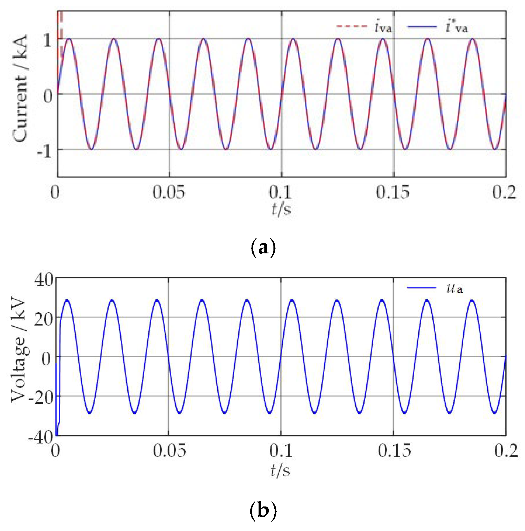
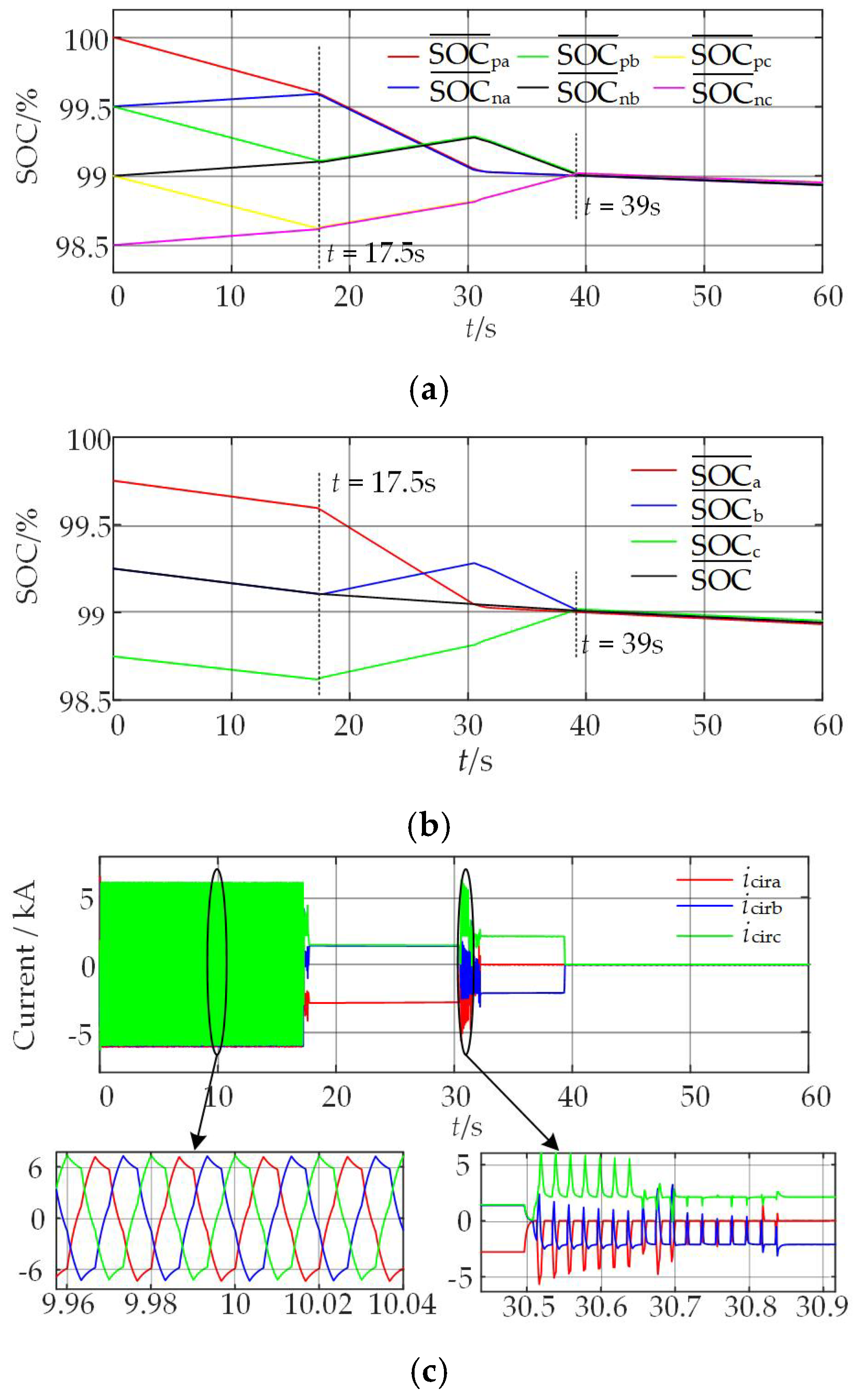
5.2. Simulation Results of the Proposed SOC-Balancing Control

The initial simulation conditions are set as follows: the average SOC values of the upper- and lower-arms of phase-a are SOC ¯ pa ( 0 ) = 100% and SOC ¯ na ( 0 ) = 99.5%, respectively; the average SOC values of the upper and lower arms of phase b are SOC ¯ pb ( 0 ) = 99.5% and SOC ¯ nb ( 0 ) = 99%, respectively; and the average SOC values of the upper and lower arms of phase-c are SOC ¯ pc ( 0 ) = 99% and SOC ¯ nc ( 0 ) = 98.5%, respectively. The overall MPC strategy is activated at 0 s, and the simulation results are shown in Figure 5 and Figure 6. Figure 5 shows the dynamic response characteristics of the AC-side current and voltage of the MMC-BESS system, and Figure 6 presents the dynamic change processes of the upper- and lower-arm average SOC values, inter-phase average SOC values, and circulating currents of each bridge arm.
As shown in Figure 5, the proposed control strategy can ensure the stable operation of MMC-BESS. Specifically, MMC-BESS can output stable fundamental frequency output voltage and output current. It is worth noting that during the inter-arm SOC-balancing control process, the basic electrical characteristics of MMC-BESS are not significantly disturbed, maintaining good dynamic performance.
The overall MPC strategy proposed in this paper demonstrates good dynamic characteristics during the SOC-balancing process, as shown in Figure 6. The control process can be divided into two main stages: inter-arm SOC balancing and inter-phase SOC balancing.
In the first stage (0–17.5 s), the system prioritizes SOC balancing between the upper and lower arms of each phase. Figure 6a,b show that the arms with higher average SOC values exhibit a decreasing trend, while those with lower values gradually increase. When the deviation of average SOC values between the upper and lower arms of each phase drops below the preset threshold δarm (0.001%), it marks the completion of inter-arm SOC balancing.
The second stage (17.5–39.0 s) mainly achieves inter-phase SOC balancing. Since phase-a and phase-b have higher initial average SOC values, the system prioritizes inserting additional submodules in these two phases. First, phase-a, which has the highest average SOC value, inserts additional submodules, causing its average SOC value to decrease while driving the average SOC values of other phases to increase. At 30.0 s, the average SOC value of phase-a approaches the total average SOC value of the three phases. Subsequently, phase-b becomes the new phase with the highest SOC and begins to insert additional submodules. Since phase-a maintains the insertion of additional submodules, phase-b submodules do not discharge to phase-a, keeping phase a SOC stable while phase-b SOC decreases and phase-c SOC continues to increase. Finally, at 39.0 s, the system achieves complete inter-phase SOC balancing.
The dynamic characteristics of the circulating currents (Figure 6c) clearly demonstrate the four stages of the entire control process. During the inter-arm SOC-balancing stage, the circulating currents are dominated by output-current components, which are used to eliminate SOC deviations between arms. After 17.5 s, the circulating currents transform to primarily DC components, manifested as negative values for phase a and positive values for phases b and c, indicating that phase a is charging phases b and c. Around 30.0 s, when phase b inserts additional submodules, since the SOC deviation temporarily exceeds the threshold δarm, the system briefly resumes inter-arm balancing control, and output current components reappear in the circulating currents. After the inter-arm SOC is rebalanced, the system continues with inter-phase balancing control, and finally achieves comprehensive balancing at 39 s, with the three phase-circulating currents reduced to zero.

5.3. Comparison with Traditional SOC-Balancing Control Method

To comprehensively verify the advantages of the MPC scheme proposed in this paper over traditional three-level SOC-balancing control, this section conducts a comparative analysis in the same MMC-BESS simulation system. Using the traditional control system described in Section 2.3, maintaining the initial average SOC values of each arm consistent with Section 5.1, and setting control parameters K1 = 100, K2 = 5, K3 = 4. After enabling the three-level SOC-balancing control at 0 s, the dynamic response characteristics of the system are shown in Figure 7.
The results indicate that the traditional scheme suffers from considerably longer balancing times: SOC balancing between the upper and lower arms of each phase takes approximately 42.0 s, while the proposed scheme requires only 17.5 s; SOC balancing between phases takes approximately 88 s, while the proposed scheme requires only 39.0 s. This comparison clearly highlights the superiority of the MPC strategy proposed in this paper in improving SOC-balancing rates.
Detailed analysis reveals the following limitations of traditional three-level SOC-balancing control: First, the selection of control parameters faces a dilemma. Although the balancing rate can be changed by adjusting K1, K2, and K3, excessive adjustment will cause overshoot in the reference values of arm voltage, affecting system operational stability. In contrast, the MPC strategy proposed in this paper does not require parameter tuning, only needing to select the maximum number of submodules for each control stage under the premise of satisfying total quantity constraints, fundamentally avoiding the overshoot problem. Second, due to the use of proportional control, the balancing speed of the traditional scheme is positively correlated with SOC deviation, resulting in slower speed as the deviation decreases. Even introducing an integral component cannot completely solve this problem. However, the MPC strategy proposed in this paper, as shown in Figure 6, achieves linear SOC reduction in each control stage, maintaining a stable balancing speed. These analysis results fully demonstrate the comprehensive advantages of the control strategy proposed in this paper in terms of balancing speed, parameter design, and dynamic characteristics.

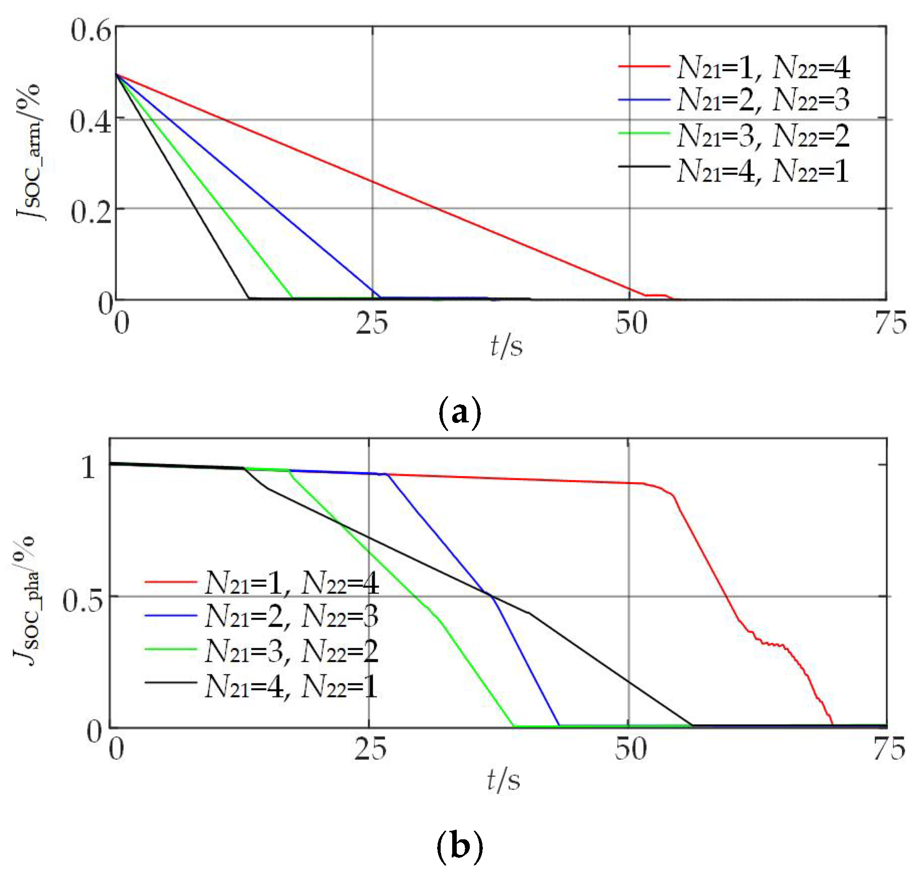
5.4. Comparison of SOC Balancing Rates with Different Submodule Number Proportions

Although the MPC system proposed in this paper cannot adjust the SOC balancing speed through traditional proportional or integral components, it can achieve balancing rate adjustment by optimizing the number of MPC submodules for inter-arm and inter-phase SOC balancing (N21 and N22).
To thoroughly investigate the impact of submodule number proportions on balancing performance, this section conducted a detailed analysis of four different proportion schemes while keeping N1 and N2 constant: (N21 = 1, N22 = 4), (N21 = 2, N22 = 3), (N21 = 3, N22 = 2), and (N21 = 4, N22 = 1). The simulation system used the same initial SOC conditions as in Section 4.2, focusing on examining the variation characteristics of the inter-arm SOC cost function JSOC_arm (using phase a as an example) and the inter-phase cost function JSOC_pha. The results are shown in Figure 8.
From Figure 8, three key findings can be found as follows: First, increasing N21 and decreasing N22 result in shorter inter-arm SOC-balancing time and improved inter-phase SOC-balancing speed. Table 3 lists detailed balancing time data for each proportion scheme, showing that the maximum number of submodules for each control section is positively correlated with the balancing rate. However, this enhancement effect exhibits diminishing returns, meaning that as the number of submodules increases, the magnitude of reduction in balancing time gradually decreases. Also, it can be seen from Figure 8b that the declining rate of JSOC_pha is not always the same which has a turning point. The reason for this phenomenon is two phase units reach SOC balancing after a certain time during the inter-phase SOC-balancing control mode.
Second, in terms of overall SOC balancing time, simply increasing N21 or N22 cannot effectively shorten the system’s overall balancing time. Research has found that when the values of N21 and N22 are close, the system can achieve relatively optimal overall balancing performance. This finding provides important guidance for parameter selection in engineering practice.
Finally, it is worth noting that although increasing N2 can also shorten SOC balancing time, this will correspondingly reduce the value of N1, thereby affecting the maximum output power of MMC-BESS. Therefore, the value of N2 should be determined based on the maximum output power requirements of MMC-BESS.

5.5. Comparison of Computation Burden Between Unified and Staged-Control Approach

In order to verify the advantages of staged control over unified control in terms of computational burden, Simulink Profiler is used to analyze the computation time of the MPC part in the simulation model under the two control schemes. The operating system is Windows 10, the CPU is i5-13600KF, and the simulation duration is set to 15 s. The CPU time results are presented in Table 4 below. It can be observed that the CPU time increases slightly as N22 increases gradually, indicating that the computational burden of staged control is marginally influenced by N22. In contrast, the CPU time for unified control is nearly 45 s, which is approximately 10 times higher than that of staged control, imposing a significantly greater computational burden on the CPU. Therefore, staged control substantially reduces the computational burden compared to unified control.

6. Conclusions

This paper proposes a fast SOC-balancing strategy for MMC-BESS based on nonlinear model-predictive control. By constructing and linearizing a nonlinear state-space model, the proposed method enables direct prediction of inter-arm and inter-phase SOC estimations with minimal computational overhead. The staged-control strategy eliminates the need for circulating current reference calculation and parameter tuning while maintaining consistent balancing speed. Simulation results indicate that the proposed method achieves inter-arm SOC balancing in approximately 17.5 s and inter-phase SOC balancing in approximately 39.0 s. In comparison, traditional three-level SOC balancing requires approximately 42.0 s and 88 s, respectively, representing reductions of 58% and 56% in balancing times for inter-arm and inter-phase SOC, respectively. Additionally, the analysis of various submodule allocation strategies offers practical insights into parameter optimization. However, the Coulomb counting method employed for SOC estimation in this study is prone to accumulating errors over time, which may lead to inaccurate SOC predictions and degrade the performance of NMPC. Future research will focus on integrating more precise SOC estimation models to enhance the balancing accuracy.

Author Contributions

Methodology, X.J.; Software, Y.Q.; Validation, D.N.; Formal analysis, Y.J. and D.N.; Investigation, F.X.; Data curation, Y.Q.; Writing—original draft, D.N.; Writing—review & editing, Q.Y. All authors have read and agreed to the published version of the manuscript.

Funding

This research was funded by China Energy Investment Corporation Co., Ltd. grant number GJNY-22-109 and the APC was funded by GINY-22-109.

Data Availability Statement

The original contributions presented in this study are included in the article. Further inquiries can be directed to the corresponding author.

Conflicts of Interest

Authors Fengxiang Xie, Yuantang Qi and Yongdong Ji were employed by CHN Energy Gonghe New Energy Development Co., Ltd. The remaining authors declare that the research was conducted in the absence of any commercial or financial relationships that could be construed as a potential conflict of interest.

References

  1. Zhang, X.; Feng, G. MMC-based PV grid-connected system with SMES-battery hybrid energy storage system. IEEE Trans. Appl. Supercond. 2024, 34, 1–4. [Google Scholar] [CrossRef]
  2. Babu, T.S.; Vasudevan, K.R.; Ramachandaramurthy, V.K.; Sani, S.B.; Chetmud, S.; Laljim, R.M. A comprehensive review of hybrid energy storage systems: Converter topologies, control strategies and future prospects. IEEE Access 2020, 8, 148702–148721. [Google Scholar] [CrossRef]
  3. Kasari, P.R.; Bhattacharjee, S. An HESS based on a modified MMCC-TSBC converter integrating energy storages. CSEE J. Power Energy Syst. 2023, 9, 1698–1709. [Google Scholar]
  4. Wang, H.; Yang, G.; Xiao, F.; Fan, X. Wide-range operation optimization strategy of bidirectional energy storage converter for 10 kV medium voltage DC integrated power system. IEEE Trans. Transp. Electrif. 2024, 10, 4604–4615. [Google Scholar] [CrossRef]
  5. Ma, Z.; Yu, F.; Zhao, X.; Gao, F. The multidimensional battery management strategy for MMC battery energy storage system. In Proceedings of the 2022 IEEE 7th Southern Power Electronics Conference (SPEC), Nadi, Fiji, 5–8 December 2022; IEEE: Piscataway, NJ, USA, 2022; pp. 1–5. [Google Scholar]
  6. He, R.; Tian, K.; Ling, Z. Offline equalization control of modular multilevel converter-based battery energy storage system. IEEE Trans. Ind. Electron. 2023, 71, 9003–9012. [Google Scholar] [CrossRef]
  7. Quraan, M.; Yeo, T.; Tricoli, P. Design and control of modular multilevel converters for battery electric vehicles. IEEE Trans. Power Electron. 2016, 31, 507–517. [Google Scholar] [CrossRef]
  8. Gao, F.; Zhang, L.; Zhou, Q.; Chen, M.; Xu, T.; Hu, S. State-of-charge balancing control strategy of battery energy storage system based on modular multilevel converter. In Proceedings of the 2014 IEEE Energy Conversion Congress and Exposition (ECCE), Pittsburgh, PA, USA, 14–18 September 2014; IEEE: Piscataway, NJ, USA, 2014; pp. 2567–2574. [Google Scholar]
  9. Maharjan, L.; Inoue, S.; Akagi, H.; Asakura, J. State-of-charge (SOC)-balancing control of a battery energy storage system based on a cascade PWM converter. IEEE Trans. Power Electron. 2009, 24, 1628–1636. [Google Scholar] [CrossRef]
  10. Luo, H.; Xu, C.; Dai, K.; Cheng, C.; Huang, Y.; Pan, F. Balance control of SOC for MMC-BESS with power fluctuation suppression, PCC voltage regulation, and harmonic mitigation in grid-connected wind farm. IEEE Access 2022, 10, 117732–117744. [Google Scholar] [CrossRef]
  11. Cheng, C.; Xu, C.; Dai, K.; Huang, Y.; Pan, F. Three-level equalization control strategy for state of charge of MMC-BESS. Power Syst. Prot. Control. 2021, 49, 100–108. [Google Scholar]
  12. Premchand, M.; Gudey, S.K. Analysis of PI, PR and SMC controllers for bidirectional converter used in electric vehicle. In International Conference on Automation, Signal Processing, Instrumentation and Control; Springer: Singapore, 2020; pp. 449–466. [Google Scholar]
  13. Xu, S.; Pei, T.; Wang, S. Model predictive control strategy of MMC based on energy decoupling. Power Electron. 2024, 58, 115–118. [Google Scholar]
  14. Cheng, Z.; Tian, F.; Yang, H.; Yang, T. Model predictive optimal control strategy for battery energy storage system of modular multilevel composite converter. Acta Energiae Solaris Sinica 2023, 44, 59–66. [Google Scholar]
  15. Wang, J.; Liu, X.; Xiao, Q.; Zhou, D.; Qiu, H.; Tang, Y. Modulated model predictive control for modular multilevel converters with easy implementation and enhanced steady-state performance. IEEE Trans. Power Electron. 2020, 35, 9107–9118. [Google Scholar] [CrossRef]
  16. Böcker, J.; Freudenberg, B.; The, A.; Dieckerhoff, S. Experimental comparison of model predictive control and cascaded control of the modular multilevel converter. IEEE Trans. Power Electron. 2014, 30, 422–430. [Google Scholar] [CrossRef]
  17. Qin, J.; Saeedifard, M. Predictive control of a modular multilevel converter for a back-to-back HVDC system. IEEE Trans. Power Deliv. 2012, 27, 1538–1547. [Google Scholar]
  18. Liu, Z.; Li, Q.; Fu, J.; Zhou, H.; Chen, J.; Xia, Z. An extended-level model predictive control method with reduced current THD for modular multilevel converter battery energy storage system. IEEE J. Emerg. Sel. Top. Power Electron. 2025. [Google Scholar] [CrossRef]
  19. Liu, Z.; Li, Q.; Zhou, H.; Fu, J.; Ren, D.; Zhang, K.; Qin, H. An improved SOC balancing strategy based on reduced computational burden voltage level model predictive control for modular multilevel converter-battery energy storage system. Electr. Eng. 2025. [Google Scholar] [CrossRef]
  20. Xu, J.; Wang, F.; Wang, J.; Li, G. SOC balancing control based on predictive power model amongst supercapacitor packs in MMC with embedded energy storage system. IEEE Trans. Power Deliv. 2023, 38, 2641–2649. [Google Scholar] [CrossRef]
  21. Zhao, G.; Shen, K.; Luo, G.; Zhao, D. A novel control strategy for modular multilevel converter with integrated supercapacitor energy storage system. In Proceedings of the IECON 2019-45th Annual Conference of the IEEE Industrial Electronics Society, Lisbon, Portugal, 14–17 October 2019; IEEE: Piscataway, NJ, USA, 2019; Volume 1, pp. 6037–6042. [Google Scholar]
  22. Sankar, S.G.; Dreke, V.D.R.; Lazar, M. Hierarchical Model Predictive Control for Modular Multilevel Converters: A Linear Parameter Varying Approach. IFAC-PapersOnLine 2024, 58, 126–131. [Google Scholar] [CrossRef]
  23. Cao, S.; Wang, Y.; Yu, X.; Yu, Y.; Yu, Z. SOC adaptive balance control strategy based on MMC-BESS. Power Supply 2024, 1–11. [Google Scholar]
  24. Tang, C.; Thiringer, T. A model predictive control method with adaptive weighting factors for enhancing performance of modular multilevel converters. IEEE J. Emerg. Sel. Top. Power Electron. 2024, 12, 3887–3899. [Google Scholar] [CrossRef]
  25. Akbari, E.; Shadlu, M.S. Integrated battery energy storage with modular multilevel converter for grid-connected photovoltaic system: Design and control. In Proceedings of the 2023 13th Smart Grid Conference (SGC), Tehran, Iran, 5–6 December 2023; pp. 1–6. [Google Scholar]
  26. Li, N.; Xie, Y.; Sha, Z.; Gao, F.; Wang, W. Hybrid predictive control method for battery integrated modular multilevel converter. In Proceedings of the 2016 IEEE 8th International Power Electronics and Motion Control Conference (IPEMC-ECCE Asia), Hefei, China, 22–26 May 2016; IEEE: Piscataway, NJ, USA, 2016; pp. 3777–3782. [Google Scholar]
  27. Li, N.; Gao, F. Hybrid model predictive control method for battery-energy-storage-based modular multilevel converter. Trans. China Electrotech. Soc. 2017, 32, 165–174. [Google Scholar]
  28. Wang, J.; Xu, J. Optimized control strategy for state-of-charge balancing of distributed energy-storage-based MMC batteries. Electr. Power Autom. Equip. 2023, 43, 44–50. [Google Scholar]
  29. Ma, W.; Sun, W.; Wang, Y.; Zhang, W.; Li, H.; Zhu, Y. MMC-based distributed energy storage system and its fast SOC balancing control strategy. Power Syst. Prot. Control. 2024, 52, 1–11. [Google Scholar]
  30. Chen, J.; Xiao, Y.; Zhou, G.; Li, X.; Luo, Y.; Zhang, W.; Wang, P.; Zhou, Y. A Hybrid Estimation Method for State-of-Charge (SOC) of Lithium-Ion Batteries. Chinese Patent CN201910460801.9; CN110133510A, 16 August 2019. [Google Scholar]
  31. Grüne, L.; Pannek, J.; Grüne, L.; Pannek, J. Nonlinear Model Predictive Control; Springer International Publishing: Berlin/Heidelberg, Germany, 2017. [Google Scholar]
  32. Vatani, M.; Bahrani, B.; Saeedifard, M.; Hovd, M. Indirect finite control set model predictive control of modular multilevel converters. IEEE Trans. Smart Grid 2015, 6, 1520–1529. [Google Scholar] [CrossRef]
Figure 1. Schematic representation of the MMC-BESS topology.
Energies 18 02502 g001
Figure 2. Control block diagram of inter-arm SOC balancing.
Energies 18 02502 g002
Figure 3. Control block diagram of inter-phase SOC balancing.
Energies 18 02502 g003
Figure 4. Staged control scheme for SOC balancing.
Energies 18 02502 g004
Figure 5. Simulation waveforms of (a) phase-a output current and (b) phase-a output voltage under proposed control strategy.
Energies 18 02502 g005
Figure 6. Simulation waveforms of (a) arm SOC average value, (b) phase SOC average value, and (c) arm-circulating-current variation during two-stage control.
Energies 18 02502 g006
Figure 7. Simulation waveforms of (a) arm SOC average value and (b) phase SOC average value under traditional three-level control scheme.
Energies 18 02502 g007
Figure 8. Dynamic characteristics of (a) inter-arm cost function and (b) inter-phase cost function under different submodule quantity ratios.
Energies 18 02502 g008
Table 1. Comparison of the existing SOC-balancing control methods for MMC-BESS.
Control MethodTechnical FeaturesMain Limitations.
Traditional three-level control [7]Open-loop proportional control and sequencing strategySlow speed and sensitive parameters
PI/PR composite control [8,9,10,11,12]Multi-stage closed-loop architectureHigh complexity and poor dynamic response
Indirect MPC [25,26,27]The SOC is indirectly balanced through the circulation cost functionThe PI/PR controller is needed
Direct MPC [25,28]Based on the SOC prediction modelOnly applicable to the submodule with DC-DC converter
Hybrid MPC [15,29]MPC with conventional controller cooperationStill dependent on parameter tuning
Table 2. Simulation parameters of MMC-BESS system.
TypeItemsValues
Circuit parametersGrid voltage35 kV
Rated output power50 MW
Equivalent inductance (Ls)2.2 mH
Equivalent resistance (Rs)10 mΩ
No. of ESMs within each arm (N)80
Arm inductance (Larm) 0.6 mH
Arm equivalent resistance (Rarm)200 mΩ
Rated capacity of battery pack (Qmax) 1000 Ah
Rated battery pack voltage (Ucell) 800 V
Control parametersControl step size100 μs
No. of ESMs for output current (N1)75
No. of ESMs for SOC balancing (N2)5
No. of ESMs for inter-arm SOC balancing (N21)3
No. of ESMs for inter-phase SOC balancing (N22)2
Table 3. Comparison of SOC-balancing time.
ConditionInter-ArmInter-PhaseOverall
(N21 = 1, N22 = 4)54.5 s15.5 s70.0 s
(N21 = 2, N22 = 3)26.0 s17.5 s43.5 s
(N21 = 3, N22 = 2)17.5 s21.5 s39.0 s
(N21 = 4, N22 = 1)13.0 s43.0 s56.0 s
Table 4. Comparison of CPU time between unified and staged-control scheme.
Control SchemeCPU Time
Unified Control45.682 s
Staged Control (N21 = 1, N22 = 4)4.882 s
Staged Control (N21 = 2, N22 = 3)4.837 s
Staged Control (N21 = 3, N22 = 2)4.808 s
Staged Control (N21 = 4, N22 = 1)4.796 s
Disclaimer/Publisher’s Note: The statements, opinions and data contained in all publications are solely those of the individual author(s) and contributor(s) and not of MDPI and/or the editor(s). MDPI and/or the editor(s) disclaim responsibility for any injury to people or property resulting from any ideas, methods, instructions or products referred to in the content.

