1. Introduction
The growing energy demand, combined with environmental concerns, is driving the need for innovative solutions to support sustainable economic development. Heat exchangers, widely used in various engineering applications such as power generation, transportation, electronics, and HVAC systems, offer a key opportunity to reduce energy consumption through efficiency improvements [
1]. In this context, additive manufacturing (AM) is revolutionizing the design and production of heat exchangers and cooling devices, enabling the integration of complex geometries that traditional manufacturing cannot achieve [
2]. The layer-wise process significantly reduces design constraints, allowing for enhanced performance, as demonstrated by numerous studies comparing AM-fabricated heat exchangers with conventional counterparts. For example, Ahmed M. Alshwairekh [
3] studied a novel double-sine-wave corrugated heat exchanger surface. The simulation results demonstrated that 3D-printed polymer heat exchangers exhibit excellent heat transfer performance. In particular, the double-sine-wave corrugated surface exceeds the single-sine-wave corrugated surface for superior thermal-hydraulic performance. Kaixin Yan et al. [
4] examined the impact of jet polishing on a gyroid heat exchanger fabricated using Laser Powder Bed Fusion (LPBF). Their results showed that the process successfully minimized pressure drop without sacrificing heat transfer efficiency. The polished prototype outperformed traditional offset strip fin heat exchangers. Other studies have focused on optimizing microchannel geometry. Arif et al. [
5] in particular investigated complex geometries in an additively manufactured evaporator channel to enhance heat dissipation in electronic devices. They explored a circular channel with a helical insert, which generated a rotational flow that improved heat transfer compared to conventional channels. Their findings demonstrated the efficacy of this design in enhancing heat dissipation.
Additively manufactured metamaterials offer significant advantages for heat exchangers by enabling complex, highly efficient geometries that enhance heat transfer while maintaining structural integrity [
6]. Advanced designs, such as triply periodic minimal surfaces (TPMSs) and lattice-based structures, maximize surface area for improved thermal performance and fluid interaction [
7,
8]. Unlike traditional manufacturing methods, AM allows for the seamless integration of intricate internal architectures, reducing weight and material waste while optimizing performance. These porous structures are particularly beneficial in applications requiring compact, high-efficiency cooling solutions, such as aerospace, automotive, and energy systems [
9]. J.Y. Ho et al. [
6] investigated two air-cooled porous lattice heat exchangers produced by LPBF and compared their performance to that of conventional fin-tube heat exchangers. These porous structures, composed of rhombi-octet unit cells, efficiently harnessed the void spaces within the water flow channels, leading to an increase in volumetric heat flux density while maintaining consistent pressure levels. As pointed out before, the design freedom offered by AM technology enables the exploration of novel surface topologies for compact heat transfer applications, including triply periodic minimal surface (TPMS) pore structures, which create two three-dimensionally separated volumes and facilitate enhanced fluid interaction. These structures are part of a class of periodic mathematical surfaces characterized by zero mean curvature. They are regarded for their significant potential in engineering and manufacturing due to their exceptional mechanical properties, high surface-area-to-volume ratio, and efficient material distribution. Additionally, their self-supporting nature makes them especially suitable for additive manufacturing processes, enabling the fabrication of complex yet high-performing geometries. Recent studies [
10,
11] have demonstrated the feasibility and advantages of TPMS-based heat exchanger designs. Additionally, AM can be leveraged to manufacture advanced heat sinks—devices that absorb and dissipate heat using a fluid medium. The ability to fabricate seamless metallic components with intricate 3D geometries enhances both heat transfer and structural integrity [
12]. Various lattice-based porous structures have been studied for air-cooled applications using both experimental and numerical approaches, including tetrahedral lattices [
13], octet truss lattices [
14], face-centered cubic lattices (FCCs) [
15], body-centered cubic lattices (BCCs) [
16], as well as face-centered cubic with vertical struts (FCCZ) [
17], and Kagome lattices [
18].
Building on promising prior research [
19], which validated the experimental methodology and setup, this study investigates the thermal and fluid dynamic performance of heat sinks incorporating various metamaterials while also exploring their manufacturability. The selection of topologies and unit cell dimensions is grounded in the literature findings, with the concurrent objective of ensuring high mechanical strength, as typically required for advanced industrial applications, such as in combustion engine components. The results offer valuable insights and data for real-world applications in cutting-edge, high-performance engineering sectors.
2. Coupons’ Geometry
2.1. Design and Manufacturing
Five different metamaterial infill structures were analyzed in this work (
Figure 1), including various configurations of lattice and gyroid structures. The metamaterials were selected based on mechanical and thermo-fluid dynamic criteria and were incorporated into an annular channel with an inner diameter of
d = 68 mm, an outer diameter of
D = 82 mm, and a length of
L = 100 mm. The cylindrical channel walls had a thickness of
Wt = 4 mm.
The first candidate infill was a lattice structure based on the BCC topology. This choice represented the best compromise among lattice structures in terms of manufacturability, compression strength, and mechanical stiffness. Moreover, as suggested by the authors of [
20], the expected pressure drops are lower compared to other topologies with similar mechanical performance. The self-supporting features of this topology facilitated easier 3D printing and powder removal. Additionally, as noted by the study of [
21], the heat exchange surface is relatively high compared to other solutions. The BCC cell size was varied on two levels,
cs = 7 mm (BCC 1) and
cs = 3.5 mm (BCC 2), obtaining an infill with two or one cell along the radius, respectively. The second lattice infill under investigation was the Octahedral topology. In this case, only
cs = 3.5 mm was produced to maximize the effect of the cell topology on the fluid flow.
The second type of metamaterials selected as candidates to enhance the heat exchange performance of the coupons was chosen considering the triply periodic minimal surface (TPMS) group. TPMS-based designs, such as gyroid, Schwarz, and diamond structures, are widely used in applications like heat exchangers, biomedical implants, and lightweight aerospace components.
The first candidate was a Schoen-G curve gyroidal structure. It was selected for its LPBF manufacturability characteristics, expected high Nusselt number (particularly at low Reynolds numbers), lower pressure drop compared to similar structures, and good mechanical strength [
21,
22]. Similarly to the BCC structure, two cell sizes (
cs = 7 mm and
cs = 3.5 mm) were produced. Moreover, two different infills were investigated. The first one (Gyroid 1) was a simple gyroidal structure oriented along the Cartesian axis. The second one (Gyroid 2) was obtained by deforming the gyroidal structure in order to obtain a geometry with the same curvature with respect to the coupon’s cylindrical wall (i.e., coupons and gyroids had the same axis of symmetry). The geometric details of the test coupons are presented in
Table 1.
The samples were positioned on the building platform with their axes aligned parallel to the growth direction. To avoid the necessity for support structures that would be difficult to remove from the internal channels, only self-supporting structures were considered.
All coupons were fabricated from AISI 316L stainless steel using an EOS M290 machine (EOS GmbH, Robert-Stirling-Ring 1, 82152, Krailing, Germany) equipped with a 1060–1100 nm 400 W ytterbium-doped fiber laser source. The initial powder consisted of spherical particles with diameters smaller than 53 μm (98.8%), and its chemical composition is provided in
Table 2. The building chamber was inertized with argon, ensuring a residual oxygen content below 0.1%.
The exposure was different depending on the characteristics of the area to be exposed. Different strategies were applied for contour and hatch scanning, as well as for standard areas, up skin, and down skin. In hatch scanning, skins were formed by scanning continuous tracks, while the infill was created by scanning 12 mm-long tracks that overlapped by 0.09 mm. To enhance material uniformity, the scan tracks were progressively rotated by 47° from one layer to the next. A restriction angle of 30° was applied to manage the interaction with the protective gas flow, ensuring that track orientations within ±15° of the gas flow direction were skipped. Additionally, in the infill regions, tracks were longitudinally shifted by 6 mm per layer to further promote homogeneity. The scanning direction was set opposite to the gas flow to optimize energy input efficiency. The processing parameters for each area are detailed in
Table 3 and reflect the current standard set by the machine manufacturer. Notably, the laser power for the down-skin contour was set to zero, meaning that this area was not exposed. This decision was made to reduce roughness, as preliminary tests indicated that down-skin contouring could degrade surface quality. To further minimize non-productive laser operation, the scanning speed was set at a high value.
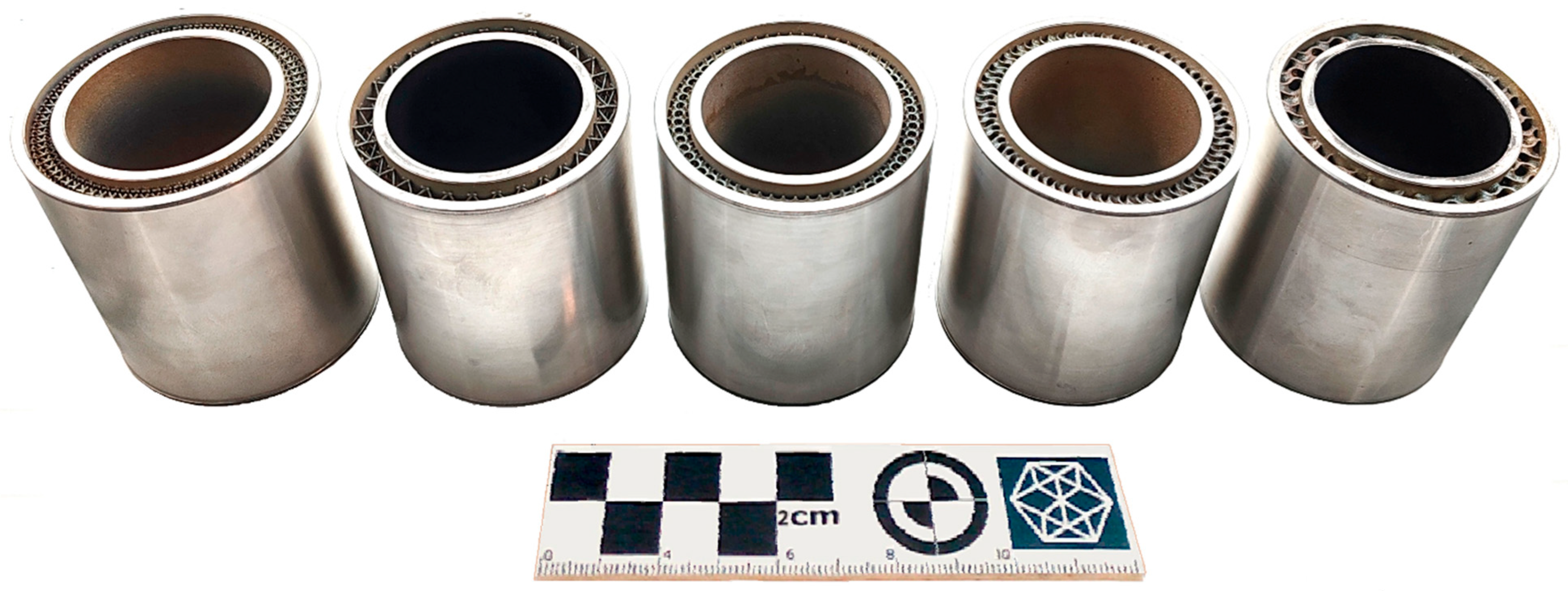
After the LPBF process, the coupons were heat-treated in a protective argon atmosphere to relieve thermal stresses. The treatment involved heating up to 550 °C over three hours, holding at that temperature for six hours, and then cooling to ambient temperature within the closed oven. Following this, the samples were sawed from the building platform and turned to achieve a smooth outer surface and ensure a watertight coupling with the experimental setup. The final samples are presented in
Figure 2.
2.2. Sample Characterization
The produced samples were thoroughly characterized with respect to the geometric and surface properties of the constituent structures to correlate the thermo-fluid dynamic behavior with the specific features of the manufacturing process.
The geometric conformity was analyzed by measuring the samples from both the top and bottom sections using a 7-axis Romer Absolute Arm equipped with a Hexagon RS5 laser scanner (Hexagon AB, Lilla Bantorget 15, SE-111 23, Stockholm, Sweden). According to ISO 10360–8 Annex D [
23], the measurement accuracy was better than ±0.048 mm. The acquired data were then post-processed by manually removing points from irrelevant surfaces and filtering out noise using a medium-high intensity statistical filter. The resulting point clouds, each consisting of approximately 500,000 points, were finally fitted to the CAD models of the corresponding samples, and the distance between the measured points and the designed surfaces was computed. The results extracted for 45° circular sectors are graphically presented in
Figure 3.
The analysis revealed that the Probability Density Functions of the dimensional deviation followed a Gaussian distribution for all the tested configurations, except for the down skin of the Octahedral structure, which exhibited a strong negative skew and a bimodal shape, likely due to the presence of both fully horizontal and vertical surfaces. The distributions were also consistently narrower for the up skins compared to the down skins, where the anomalies were expectedly concentrated due to heat penetration through the solid substrate, leading to the formation of dross that can increase the thickness of horizontal surfaces by up to about 0.3 mm. The only exception was observed in BCC 1, where the orientation of the beams likely reduced laser penetration, while their length amplified thermal deformations, which might have consequently assumed a dominant role. However, the dimensional deviation remained consistently within ±0.25 mm (>90% of points), with average absolute values comparable to the accuracy of the measuring instrument (
Table 4). Therefore, it can be concluded that the geometric conformity of the produced structures is excellent and well suited for real industrial applications. From a manufacturing perspective, the only consideration is the need for supports to begin the construction of the Octahedral, Gyroid 1, and Gyroid 2 structures.
The surface roughness was instead analyzed by examining the samples from both the top and bottom sections using a Sensofar S Neox Five-Axis 3D microscope (Sensofar Tech SL, Parc Audiovisual de Catalunya, Ctra. BV-1274 KM 1, 08225, Terrassa, Spain) equipped with a Nikon EPI 5× objective. Specifically, 13.5 × 24 mm
2 areas were scanned using a green light source (530 nm) and stitching the field-of-views together with a 25% overlap. The spatial sampling in the vertical and in-plane directions was 12 µm and 1.38 µm, respectively. To optimize image acquisition, the lamp brightness and microscope sensitivity were calibrated to mitigate dark spots. According to ISO/IEC guide 98–3:2008 GUM:1995 [
24], the measurement accuracy was better than ±600 nm with a 95% confidence level. The acquired data were then post-processed to extract 4.8 mm-long profiles from regions with sufficiently continuous features and to obtain the roughness average (R
a [µm]) and mean roughness depth (R
z [µm]) in accordance with the ISO 4287 [
25] standard, using a cut-off wavelength of λ
c = 0.8 mm. The obtained results are presented in
Table 5.
The analysis revealed that the up skins of the gyroid structures exhibit higher Ra and Rz values compared to the lattice structures due to the staircase effect caused by discretizing the undulating surfaces into layers. In contrast, no significant differences were observed on the down skins, where the formation of dross dominated over the stair-step effect, resulting in roughly double the roughness and similar values across the different structures. Only for the gyroids was Rz similar or even higher on the up skins compared to the down skins, likely due to the frequent scanning of very small areas at the tops of the saddles forming the gyroids, where heat accumulation can lead to the formation of spatters and bulges. Overall, the observed roughness values were consistent with the typical ranges that characterize the LPBF process.
2.3. Production Cost Analysis
The manufacturing cost is a crucial factor to consider in this study. The primary parameters influencing cost include the mass of the coupons, material expenses, and process time, while other cost factors remain constant due to the geometric similarity of the samples. The process times for BCC 1, BCC 2, Octahedral, Gyroid 1, and Gyroid 2 were 24 h and 17 min, 48 h and 32 min, 24 h and 20 min, 24 h and 21 min, and 48 h and 1 min, respectively. Meanwhile, their corresponding masses were 1.64 kg, 1.86 kg, 1.76 kg, 2.03 kg, and 1.88 kg. The data indicate that manufacturing costs are generally similar across all samples, except for Gyroid 2 and BCC 2, which require longer processing times. Notably, BCC 1 stands out as the lightest and most cost-effective structure, a benefit that becomes even more significant when scaling up production for larger heat sinks.
3. Experimental Apparatus and Procedure
3.1. Experimental Test Rig
As mentioned in the Introduction, this work is an extension of a previous study, and, therefore, the same experimental approach was adopted. For this reason, only the main features of the test rig are reported here, while specific details can be found in the study of [
19].
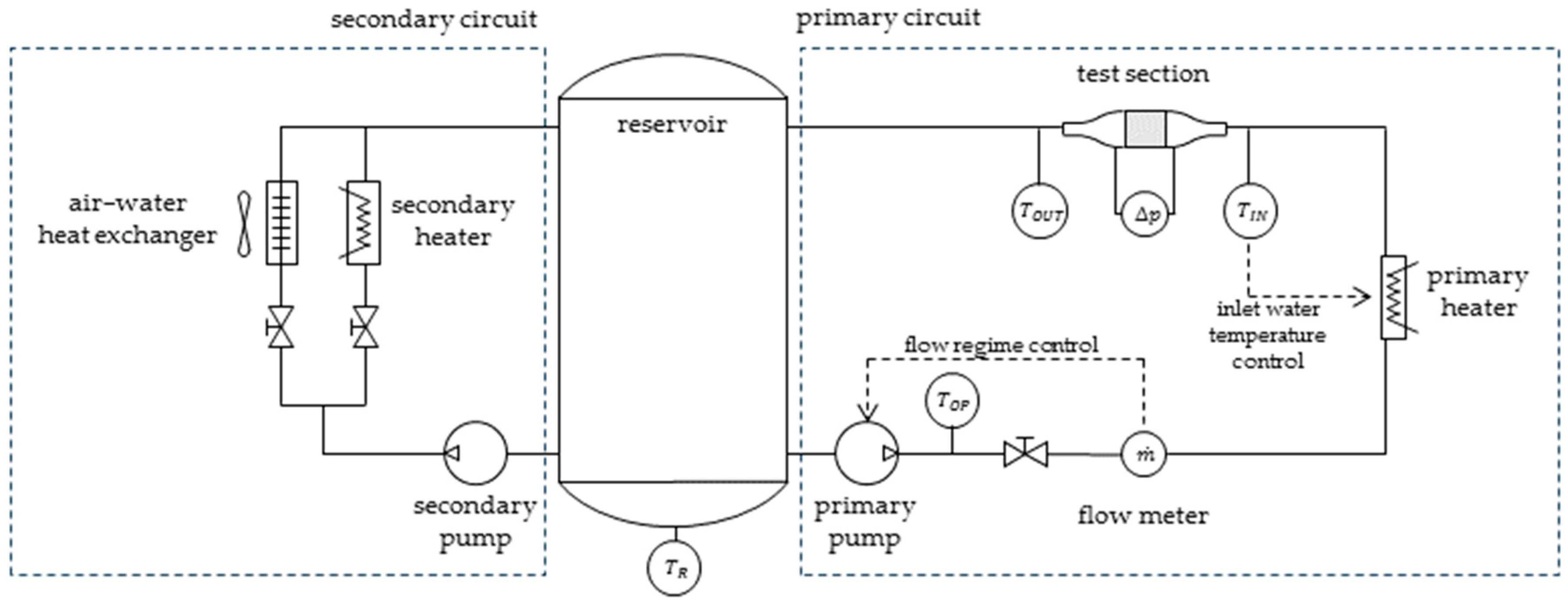
A schematic of the facility layout is shown in
Figure 4. A 300 L atmospheric reservoir connects two independent circuits: a primary circuit, where the test section was installed, and a secondary circuit, which regulates the reservoir water temperature using a 12 kW electric heater and a 3 kW dry cooler.
In the primary circuit, water was drawn from the reservoir by a variable-speed centrifugal pump. Before entering the test section, it passed through a digital magnetic flow meter (YEWFLO DY025-S2 (Yokogawa Electric Corporation, Nakacho 2-chome 2- 9-32, 180-8750, Musashino-shi, Japan), 0–300 kg/min range, ±1.0% uncertainty) and a 6 kW electric heater, which fine-tuned the water temperature to the desired value. In the present experimental campaign, the magnetic flow meter replaced the two orifice plates originally installed [
19], ensuring better accuracy across all investigated flow regimes.
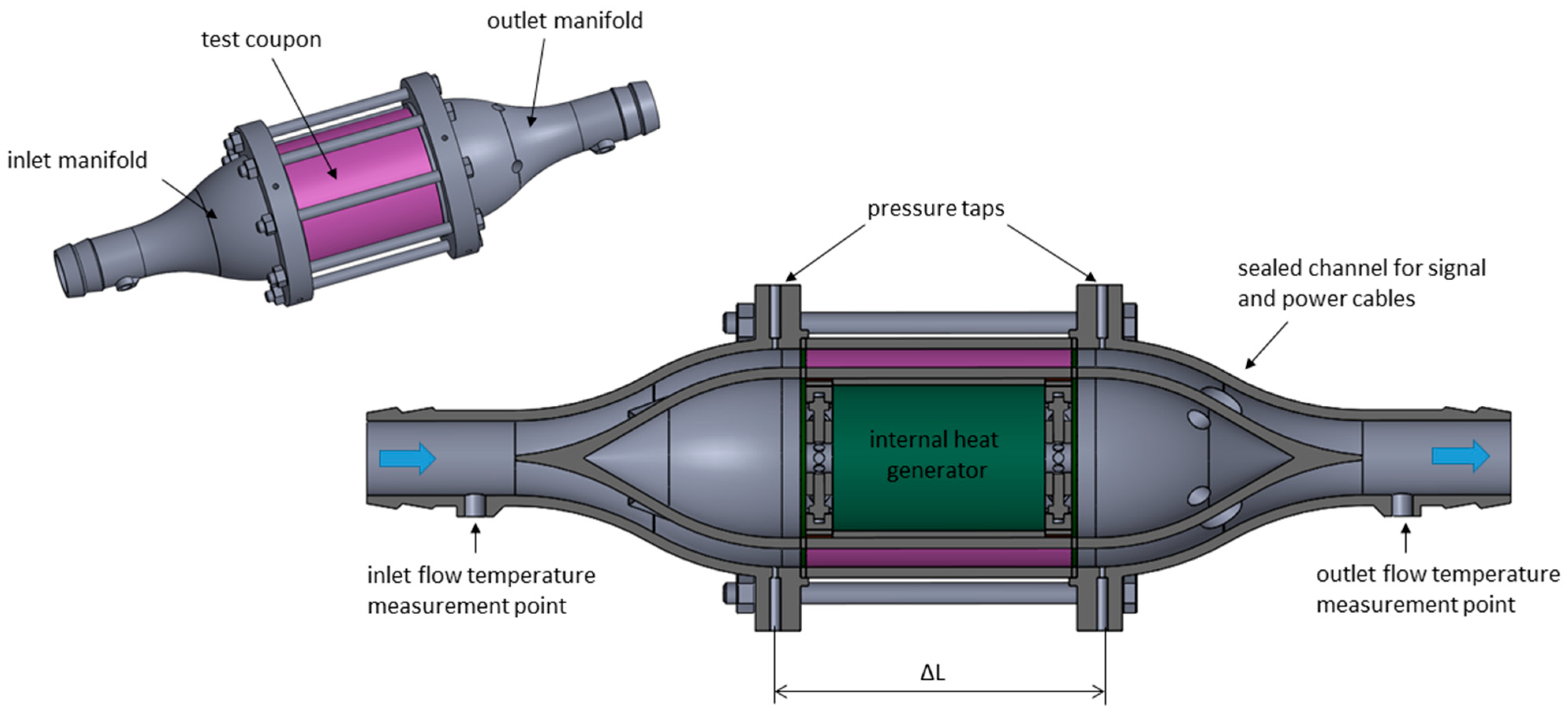
Flow temperatures across the test section were measured by two Pt 100 probes (1/10 DIN class), installed inside the inlet and outlet manifolds. These manifolds connect to the specimens via flanges and a gasket, which also served as a thermal break (
Figure 5). Pressure ports, located in the same flanges, are connected to a digital pressure transducer (0–1000 mbar range, 0.1% accuracy) to measure the pressure drop across the specimen.
It is important to note that the inlet manifold was conceived to transition from the 1 1/4-inch inlet line to the annular channel of the coupons while preventing the separation of the flow or the generation of undesirable flow structures. Even though this geometry does not enable the full development of the flow entering the test coupons, it ensured repeatable conditions while maintaining a compact and cost-effective design. In addition, any incoming flow structure was quickly disrupted by the turbulators inside the channel, whose length is adequate to reduce edge effects.
To optimize the manufacturing process, the exit manifold adopted the same geometry as the inlet manifold, except for four holes required to route signal and power cables from inside the coupon. Due to their complex shape, the manifolds were fabricated using the same LPBF machine that produced the coupons.
To supply internal thermal power, the system shown in
Figure 6 was used. The heat flux was generated by the Joule effect through two 25 µm-thick Inconel 665 alloy foils connected in series to a 2400 W DC power supply.
A temperature-resistant paper sheet, capable of withstanding up to 220 °C, was used to electrically isolate the Inconel foils from the metal coupons. Particular care was taken to ensure optimal thermal contact between the heating system and the internal wall of the coupon by using specially designed clamps, as well as to provide a uniform power supply to the Inconel foils through curved copper bus bars [
19].
For data reduction purposes, as will be explained later, it was necessary to monitor the temperature profile across the heater surface. This was achieved using six T-type thermocouples in direct contact with the Inconel foils, positioned along two opposite generatrices of the cylindrical surface, with three equally spaced sensors on each side (
Figure 6).
The test section assembly, including both manifolds and test coupons, was then wrapped in a thick layer of rock wool to minimize thermal losses to the environment.
The inlet water temperature was kept constant through closed-loop control of the electrical heater, and measurements were taken only after steady-state thermal conditions were reached. A steady state was considered achieved if the outlet flow temperature and heater temperature varied by no more than ±0.05 °C over a 10 min interval. Heat input was also regulated to ensure that the average temperature of the internal surface of the test section was approximately 60 °C higher than the temperature of the inlet water.
Eight flow rate values were tested, ranging from Re = 2000 to 12,000. Data were sampled at 0.5 Hz over a 5 min period and subsequently ensemble-averaged to compute the performance parameters.
To eliminate the effects of temperature-dependent water properties, pressure losses were analyzed separately from heat transfer, with both the test section and water flow maintained under isothermal conditions.
3.2. Data Reduction
The manufacturing thermo-hydraulic performance will be presented in non-dimensional form using the friction factor (
f) and the Nusselt number (
Nu) as functions of the Reynolds number (
Re). The Reynolds number is calculated according to Equation (1), based on the inlet water properties and the hydraulic diameter.
where
is the bulk velocity obtained from the mass flow rate
, the cross-sectional area
,
is the water density evaluated at the test section inlet conditions, and
is the dynamic viscosity.
The hydraulic diameter, (
Dh [m]), refers to the smooth channel and is calculated using Equation (2), resulting in a value of 14 mm.
The choice to use the definition of the Reynolds number in Equation (1) allows for a straightforward comparison of performance across different internal geometries. This would not have been possible with an alternative choice of characteristic length—such as one based on the hydraulic diameter of the internal structure (4 × Wetted Volume/Wetted Surface)—or a different reference velocity (e.g., the maximum velocity at the minimum cross-sectional area).
The friction factor is defined in Equation (3), where
represents the distance between the pressure taps (
Figure 4), and the water density
is again evaluated at the test section inlet conditions.
Since the inlet and outlet cross-sections have the same areas, the static pressure difference Δp [Pa], truly represent the total pressure drop.
The Nusselt number
calculation (Equation (4)) is based on the log mean temperature
(Equation (5)).
In Equation (4),
represents the reference area, defined as the internal cylindrical surface of the smooth coupon in contact with the water flow, with a diameter of
,
is the thermal conductivity, and
denotes the heat power supplied by the internal heat generator via the Joule effect and is calculated according to Equation (6).
In Equation (5),
and
represent the outlet and inlet temperatures of the water, respectively, while
is the temperature of the reference surface. The latter is computed starting from the average temperature
of the six thermocouples mounted on the Inconel foils and the simple one-dimensional conduction analysis described in detail in [
19] and expressed by Equation (7).
where
[K/W] is the overall thermal resistance due to the series of heater foil, the insulating layer (paper sheet and thermally conductive paste), and the coupon wall, as illustrated in
Figure 6. Since data are taken only after steady thermal conditions are reached,
remains constant during the acquisition (±0.05 °C).
The actual power
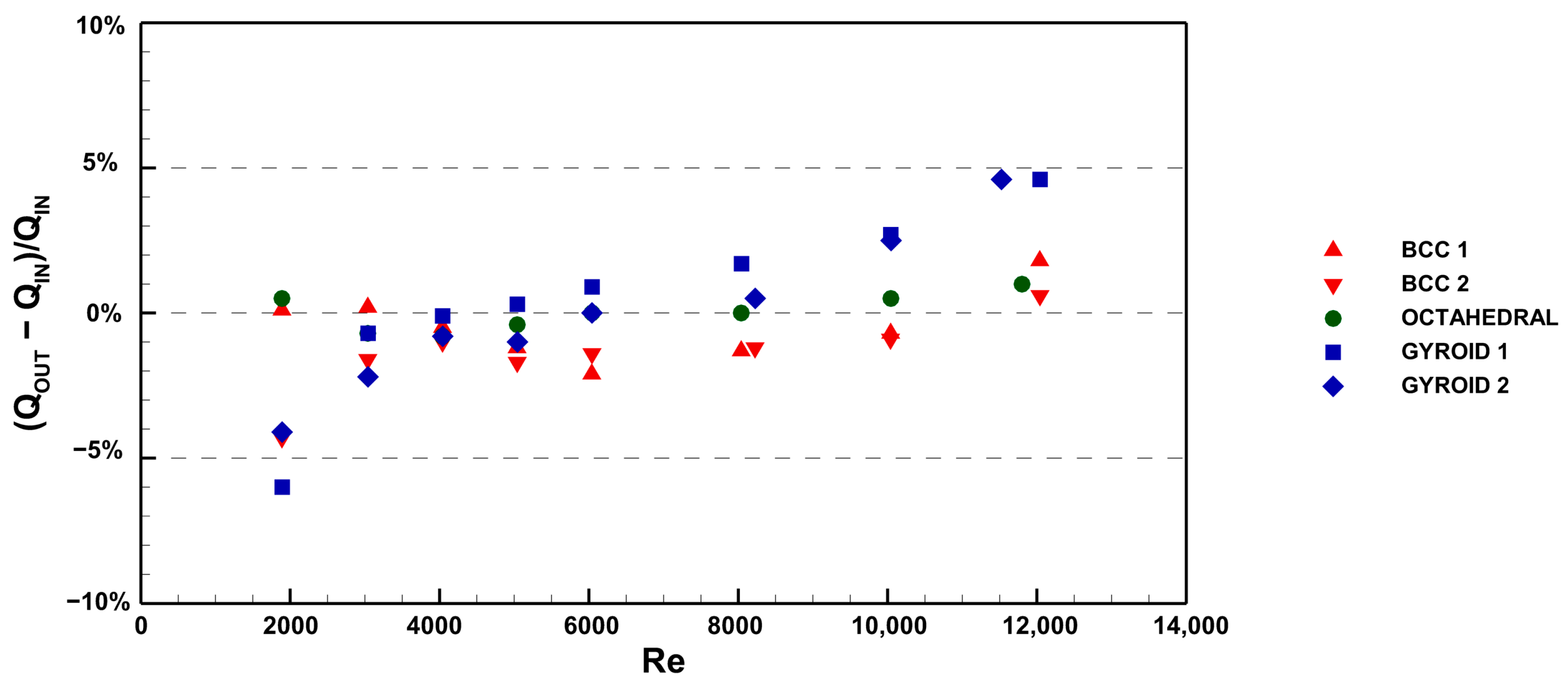
transferred to the fluid (Equation (8)) differs from the input power due to unavoidable thermal losses to the environment and conduction within the test rig itself. Additionally, the Pt100 probe at the outlet section may not fully capture potential temperature gradients or spatial inhomogeneities across the flow area. To address these issues, particular care was taken in the design and development of the test apparatus to minimize conductive losses by thermally isolating the testing section with a thick layer of rock wool, and the energy balance was investigated.
Figure 7 shows that the experimental dataset is within ±3%, with only a few points reaching values around ±5%. Therefore, it can be concluded that thermal losses and the measurement approach introduce only negligible errors, accounting for only a small percentage of the input power. Consequently, a model to compensate for these factors was not considered, and the heat transfer coefficient was calculated based on the electrical input power.
The experimental repeatability and uncertainty were ultimately assessed to demonstrate the robustness of the adopted experimental approach. Specifically, repeatability was evaluated by conducting five repeated tests on two different geometries. The results deviated by no more than 5% from their mean, indicating excellent consistency of both the experimental rig and methodology. Uncertainty for the performance parameters was assessed using the Kline and McClintock method [
26], along with the specific data outlined in [
19]. Accordingly, only the upper estimates are reported here. The uncertainty was found to be less than 3% for the Reynolds number, less than 4.5% for the friction factor, and less than 12% for the Nusselt number.
4. Results and Discussion
The thermo-hydraulic performance, consistent with previous work, will be presented by normalizing both the friction factor and the Nusselt number using the respective values previously obtained for the smooth annular channel geometry [
19]. By doing so, rather than relying on normalization based on the literature correlations, the effectiveness of the internal structure compared to the smooth surface will be more clearly highlighted, as it is tested under the same fluid dynamic conditions.
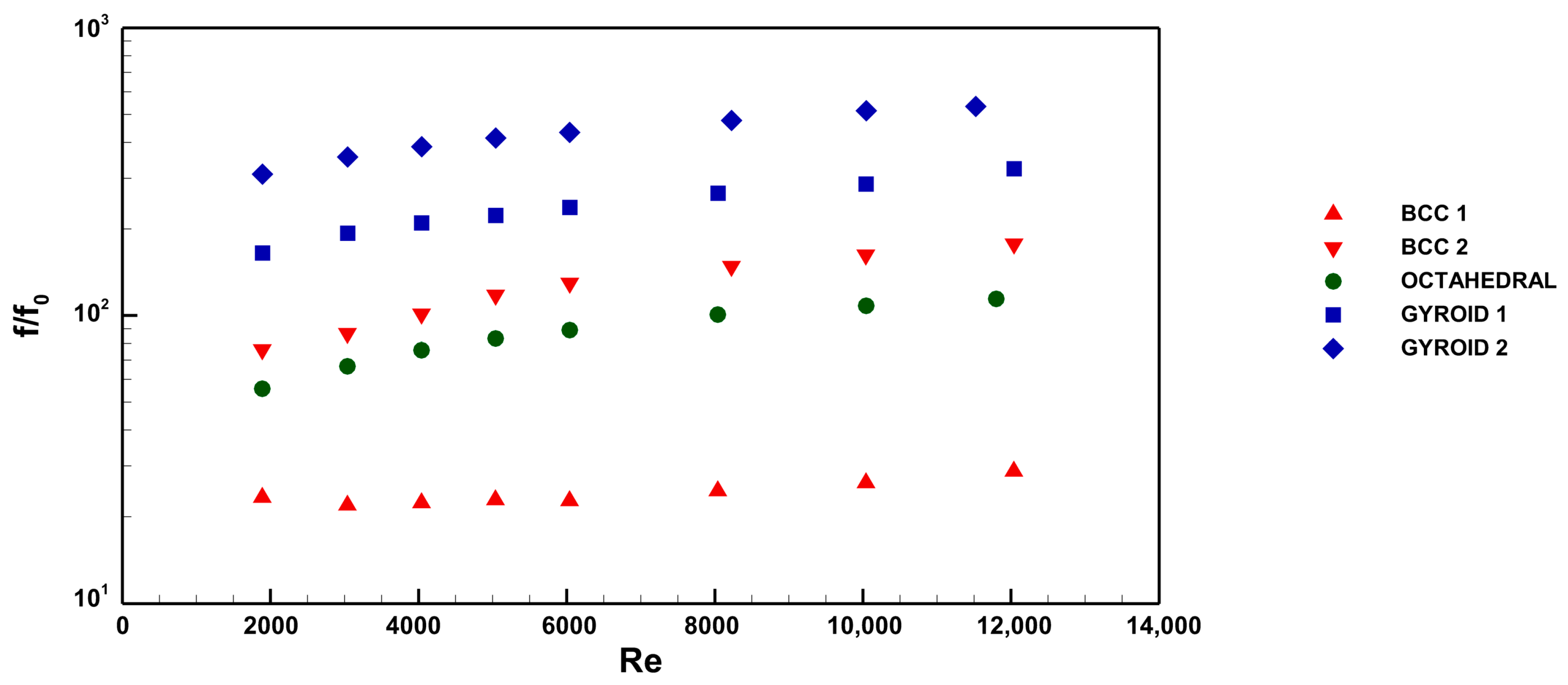
Figure 8 shows the normalized friction factor
as a function of the Reynolds number, representing the pressure drops across the coupons. Here,
is the friction factor of the smooth coupon, as reported in the study of [
19]. As expected, the pressure drops, compared to the smooth channel values, increases with the Reynolds number for all configurations, with different trends depending on the specific infill. In particular, BCC 1 experiences the lowest pressure losses. This coupon has a cell size of 7 mm and the lowest wetted surface area among all specimens, resulting in lower skin friction drag.
For the Octahedral infill, the pressure drop increases sharply due to its smaller cell size of 3.5 mm, which doubles the wetted surface area compared to BCC 1. Depending on the Reynolds number, the pressure drop rises by a factor of 4 to 5. The BCC 2 configuration is identical to BCC 1, except for the cell size. Reducing the cell size from 7 mm to 3.5 mm leads to a pressure drop increase of 6 to 7 times. Despite the wetted surface area doubling compared to the Octahedral infill, BCC 2 exhibits only a slightly higher pressure drop. This result underscores the critical role of infill topology. This finding is further confirmed by the fact that both gyroidal infills exhibit the highest pressure drops among all coupons, even though their wetted surface areas are comparable to that of the BCC 2 configuration. This evidence can be explained by the continuous change in direction imposed on the fluid by the gyroidal structure.
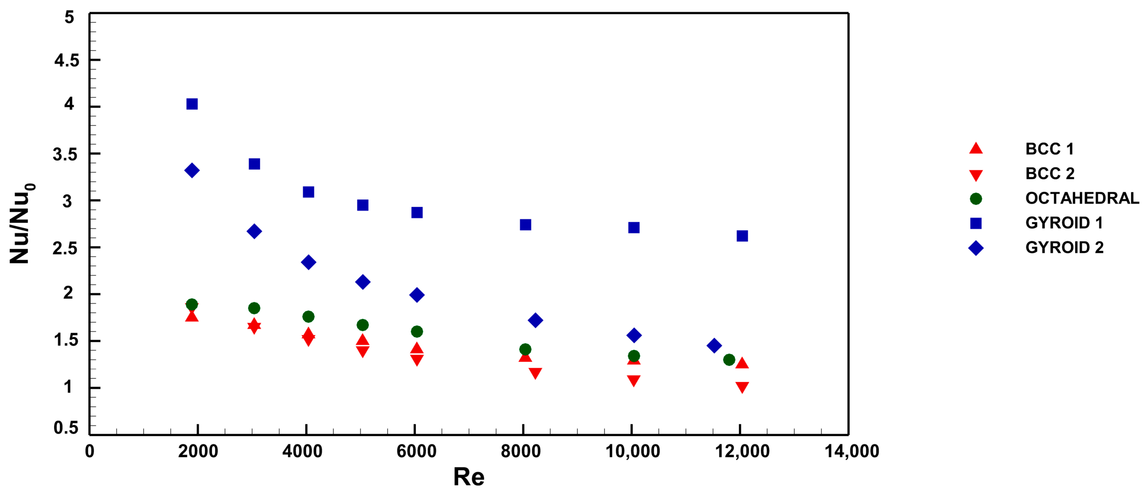
Figure 9 presents the heat transfer performance of the samples, expressed as the Nusselt number increase relative to the smooth annular channel. The investigated geometries improve heat transfer compared to the smooth channel, with performance differing according to the infill topology. Overall, a decreasing trend is observed with increasing Reynolds number, especially for the gyroidal coupons.
Although the BCC 2 configuration features the largest wetted surface area and experiences a significant pressure drop, it exhibits the lowest heat transfer performance among all the examined cases. The BCC 1 and Octahedral configurations exhibit comparable performance, demonstrating only a marginal improvement in heat exchange efficiency relative to BCC 2. These results suggest that infill topology is the most critical factor influencing heat transfer.
Configurations incorporating the gyroidal infill achieve significantly higher thermal performance compared to the others, with improvements ranging from 1.5 to 4 times. The best-performing configuration is the gyroidal infill with a cell size of 7 mm, despite having a lower wetted surface area and pressure drop than the coupon with a 3.5 mm cell size. This finding further confirms that infill topology is the primary driver of heat exchange performance.
Figure 10 illustrates the Nusselt number enhancement versus friction factor augmentation, comparing the results with those previously obtained for pin-fins [
19]. The BCC 1 geometry offers a heat transfer performance comparable to pin-fins with H/d = 2 oriented at 90°, but with lower pressure losses.
The BCC 2 and Octahedral infills exhibit similar heat transfer performance to BCC 1 but with higher pressure losses, even exceeding those of the pin-fins. Configurations incorporating gyroidal structures provide excellent heat transfer performance. However, their pressure losses are significantly higher compared to coupons integrating pin fins.
Overall, the most promising configuration is BCC 1 for its low-pressure losses and Gyroid 1 for its outstanding heat transfer performance and superior mechanical strength compared to pin fins, particularly when higher pressure losses do not negatively impact the application.
Determining the most suitable metamaterials infill for a potential cooling application requires considering both pressure drops and heat exchange performance. Tian et al. [
27] introduced the thermal efficiency index to evaluate the trade-off between increased pressure losses and heat transfer enhancement.
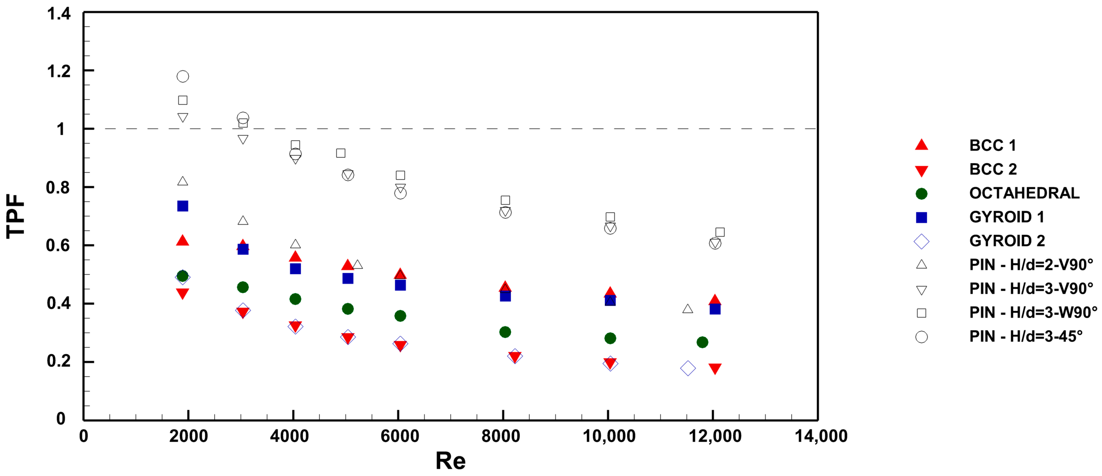
For this analysis, the thermal performance factor (TPF) is used, defined as the ratio of the thermal efficiency index of each configuration to that of the smooth channel (Equation (9)).
Based on its definition, a TPF greater than unity indicates better efficiency with respect to the smooth channel, while a TPF < 1 means that heat transfer enhancement is obtained at the cost of very high pressure drops.
The results are presented in
Figure 11, where, again, for the sake of completeness, the data from the previous investigation [
19] are also reported. Analyzing the data presented in the figure confirms some of the observations made based on
Figure 10. Coupons incorporating BCC 2, Octahedral, and Gyroid 2 structures exhibit the lowest performance among the investigated geometries, while the BCC 1 and Gyroid 1 configurations achieve a heat sink efficiency close to that of pin fins, although generally lower. The main advantage of the BCC 1 and Gyroid configurations lies in the excellent structural strength provided by the porous material within the annular channel.
Generally speaking, it can be concluded that the adoption of a particular infill structure can mainly be justified by the requirement to fulfill other constrains, e.g., the structural strength that cannot be sustained by the empty smooth channel, or the need to manage high thermal loads even at the cost of much more pumping energy.
5. Conclusions
This study investigated the thermo-hydraulic performance of water-cooling annular channels filled with diverse metamaterials. The annular geometry was thought to be representative of the conditions typical of internal combustion engines. The test coupons were manufactured by means of the Laser Powder Bed Fusion (LPBF) technology, comparing their pressure drop and heat transfer characteristics to a smooth reference channel. The primary goal was to gather reliable data to determine the optimal heat sink configuration for each specific application.
A set of five annular coupons was fabricated using AISI 316L stainless steel, each incorporating a distinct metamaterial with varying topologies and unit cell dimensions. Each topology was selected to comply with the design limitations inherent to the LPBF process.
The infill structures were characterized using laser scanning and confocal microscopy. The findings demonstrated the capability of the LPBF process to finely reproduce the examined structures, although minor flaws attributable to the inherent limitations of the process were primarily observed on the upper surfaces.
A custom-designed test facility was constructed to measure heat transfer and pressure drop and was used to evaluate each test coupon. Among the tested configurations, the BCC 1 infill demonstrated the lowest pressure drop due to its larger cell size and reduced wetted surface area. Conversely, the Octahedral and BCC 2 configurations, characterized by smaller cell sizes, experienced substantially higher pressure losses—highlighting the impact of infill topology on flow resistance. Notably, gyroidal structures exhibited the highest pressure drops due to their complex geometries, which force continuous changes in fluid direction.
Regarding heat transfer performance, all configurations outperformed the smooth reference channel, with varying degrees of improvement. The gyroidal structures provided the most significant heat transfer enhancements, achieving up to four times the Nusselt number augmentation. However, this improvement came at the cost of considerably higher pressure losses. Surprisingly, the BCC 2 configuration, despite having a high wetted surface area, exhibited the lowest heat transfer enhancement, emphasizing that increased surface area alone does not guarantee superior performance.
A comparison of thermal performance against friction factor augmentation indicated that, while some configurations, such as BCC 1, achieved performance comparable to pin-fin arrangements with lower pressure losses, others, like BCC 2 and Octahedral, demonstrated efficiency drawbacks due to excessive pressure penalties. The analysis using the thermal performance factor (TPF) further confirmed that most infill structures are not thermally efficient for practical applications unless additional structural or thermal constraints justify their adoption.
Ultimately, the choice of an internal infill structure should be dictated by specific application requirements. The BCC 1 configuration emerges as a promising candidate for applications requiring low-pressure losses, while the Gyroid 1 configuration is advantageous for high-thermal-load scenarios where increased pumping energy is acceptable. However, in general, pin-fin arrangements remain preferable for thermo-hydraulic efficiency, especially at Reynolds numbers below 3000. Future studies should explore optimization strategies to balance heat transfer enhancement with manageable pressure losses, considering practical implementation constraints.


