1. Introduction
The extensive reliance on fossil fuels for energy production has led to significant environmental challenges, making the reduction of carbon emissions a critical priority [
1]. Advancing new technologies or improving existing processes in line with sustainability standards while incorporating alternative products such as methanol and DME is essential for generating clean and cost-effective energy and chemicals while mitigating economic and energy drawbacks. However, establishing sustainable industrial processes remains a significant global challenge for the chemical sector. Integrating sustainability principles into process design plays a key role in overcoming this challenge by reducing or eliminating negative environmental impacts [
2,
3]. On the other hand, hydrogen has garnered worldwide interest due to its significant potential as a vital energy carrier, with applications spanning both stationary and mobile energy systems. It offers a promising solution to current energy challenges; however, widespread adoption hinges on significantly lowering production costs, as affordability remains a key driver for the expansion of the hydrogen economy [
4]. Conventional hydrogen production methods, such as steam methane reforming and coal gasification, contribute significantly to greenhouse gas emissions. In contrast, sustainable alternatives, including renewable energy sources, high-efficiency power generation technologies like the Allam–Fetvedt cycle, and green hydrogen production via electrolysis, offer considerable environmental advantages over existing methods [
5,
6].
Dimethyl ether (DME) has gained significant attention as a promising hydrogen carrier due to its favorable chemical properties, sustainability potential, and compatibility with existing infrastructure. It can be easily reformed to produce hydrogen on demand, eliminating the need for complex and energy-intensive storage systems. Moreover, DME is compatible with existing fuel infrastructure, including pipelines and storage tanks, reducing the cost and complexity of transitioning to a hydrogen-based energy system [
7,
8,
9]. DME’s role as a hydrogen carrier is expected to grow as hydrogen demand increases for transportation, power generation, and industrial applications. Countries investing in hydrogen infrastructure, particularly those with renewable energy surpluses, consider DME as a viable option for hydrogen logistics. However, key challenges remain, including the scalability of green DME production, the development of efficient reforming technologies, and regulatory support for its widespread adoption. As advancements in catalysis, carbon capture, and renewable hydrogen production improve, DME has the potential to play a pivotal role in bridging the gap between conventional energy sources and a fully decarbonized hydrogen economy. Its ability to seamlessly integrate into existing energy systems while enhancing sustainability makes it a compelling solution for the future of clean energy [
10].
Process integration is a systematic approach to designing and optimizing industrial processes to improve energy efficiency, resource utilization, and environmental sustainability. It plays a crucial role in the production of energy and chemicals by enhancing process efficiency, reducing waste, and minimizing the overall environmental footprint. By integrating heat, mass, and utility flows within industrial systems, process integration contributes to achieving sustainable and cost-effective production [
11,
12]. The importance and principles of process integration in sustainable energy and chemical production can be listed as heat and mass integration, energy efficiency improvement, reduction of carbon emissions, optimization of resource use and waste minimization, facilitation of renewable energy integration, economic benefits, and process intensification. Process integration is expected to play an increasingly critical role in the decarbonization of industries and the transition to sustainable energy systems. Advanced digitalization techniques, such as digital twins and AI-driven optimization, will further enhance its effectiveness. As regulatory pressures to reduce emissions increase, process integration will be key to achieving industrial sustainability goals [
13,
14,
15,
16].
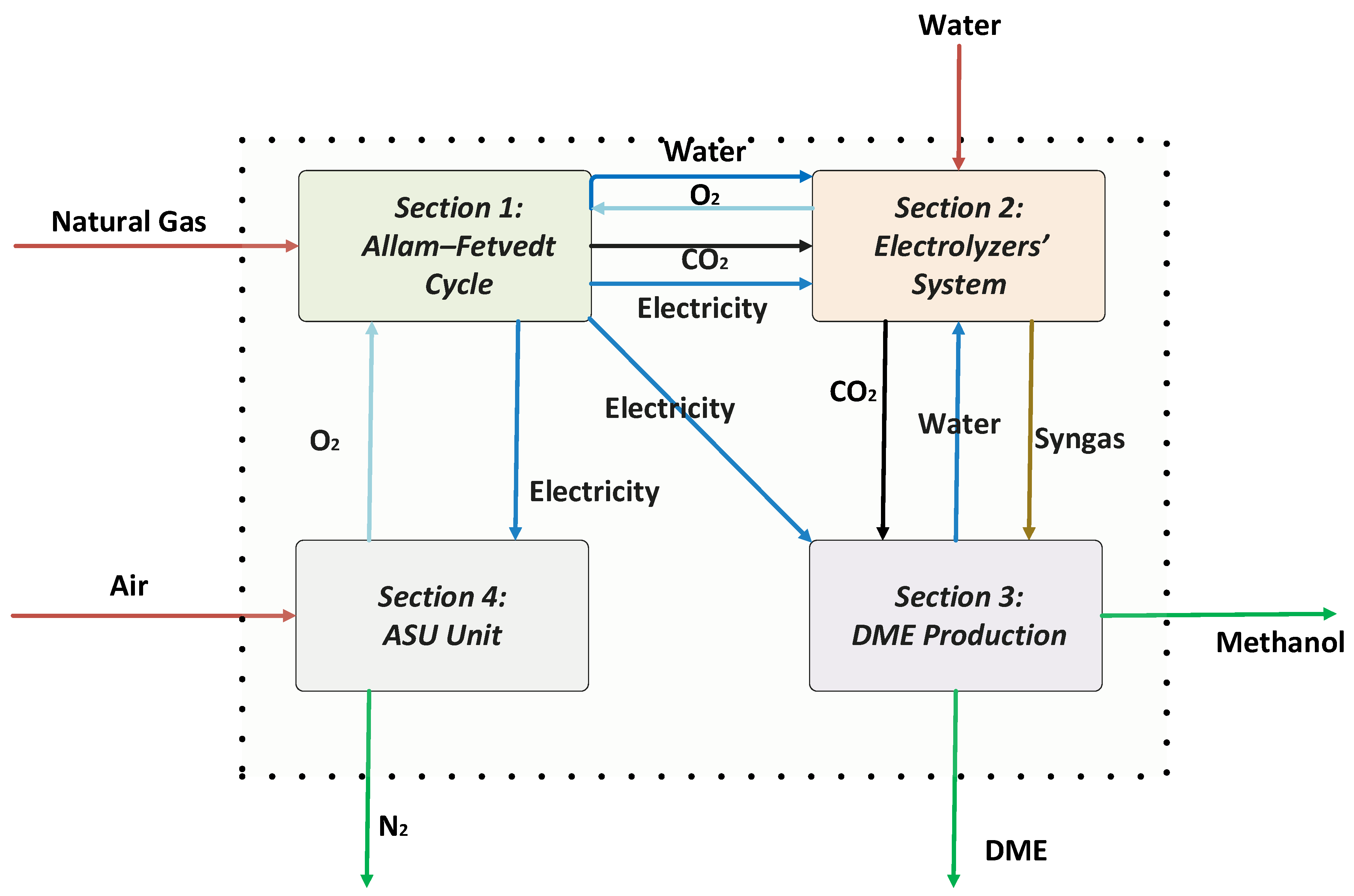
This study aims to design and simulate an innovative, fully integrated process for the co-production of power, hydrogen, and dimethyl ether (DME), targeting enhanced sustainability and energy efficiency. The suggested system uses the Allam–Fetvedt cycle to generate power while capturing carbon, a solid oxide co-electrolyzer to produce syngas and hydrogen from water and carbon dioxide, and a unit that makes dimethyl ether (DME) from methanol. In this paper, we aim to achieve the following objectives: (1) Develop an integrated process that efficiently combines power generation using the Allam–Fetvedt cycle, hydrogen production and syngas generation using the H2O and CO2 electrolyzer system, and DME synthesis; (2) implement and analyze heat and mass integration to maximize resource utilization and minimize energy losses; (3) develop a detailed process simulation using Aspen HYSYS to assess the feasibility and performance of the integrated system and evaluate key performance indicators, such as energy efficiency and production rates; (4) assess the carbon footprint and environmental benefits of the proposed system compared to conventional hydrogen and DME production methods; and (5) identify key challenges and opportunities for the commercial implementation of the proposed system. The structure of the paper reflects this comprehensive approach. It begins with an introduction that outlines the motivation for sustainable chemical and energy production and highlights the advantages of hydrogen and DME in the transition to low-carbon energy systems. This segment is followed by a detailed description of the integrated process, which is divided into four sections covering the Allam–Fetvedt power cycle, the electrolyzer system, DME synthesis, and the air separation unit. The simulation section explains how each unit was modeled in Aspen HYSYS, supported by flow diagrams and stream data. The results and discussion section provides an in-depth analysis of material and energy efficiencies, carbon emissions, and the system’s alignment with net-zero targets. The paper concludes by summarizing the system’s potential to contribute to clean energy goals and calls for future techno-economic and life cycle assessments to further validate its industrial feasibility.
3. Aspen HYSYS Simulations
Upon defining the characteristics, the simulation was conducted using the ASPEN HYSYS V13 software. The fluid package was selected based on the process specifications. The thermodynamic properties were calculated via the Peng–Robinson equation of state (EOS). In this study, the natural gas feed composition is shown in
Table 1 below.
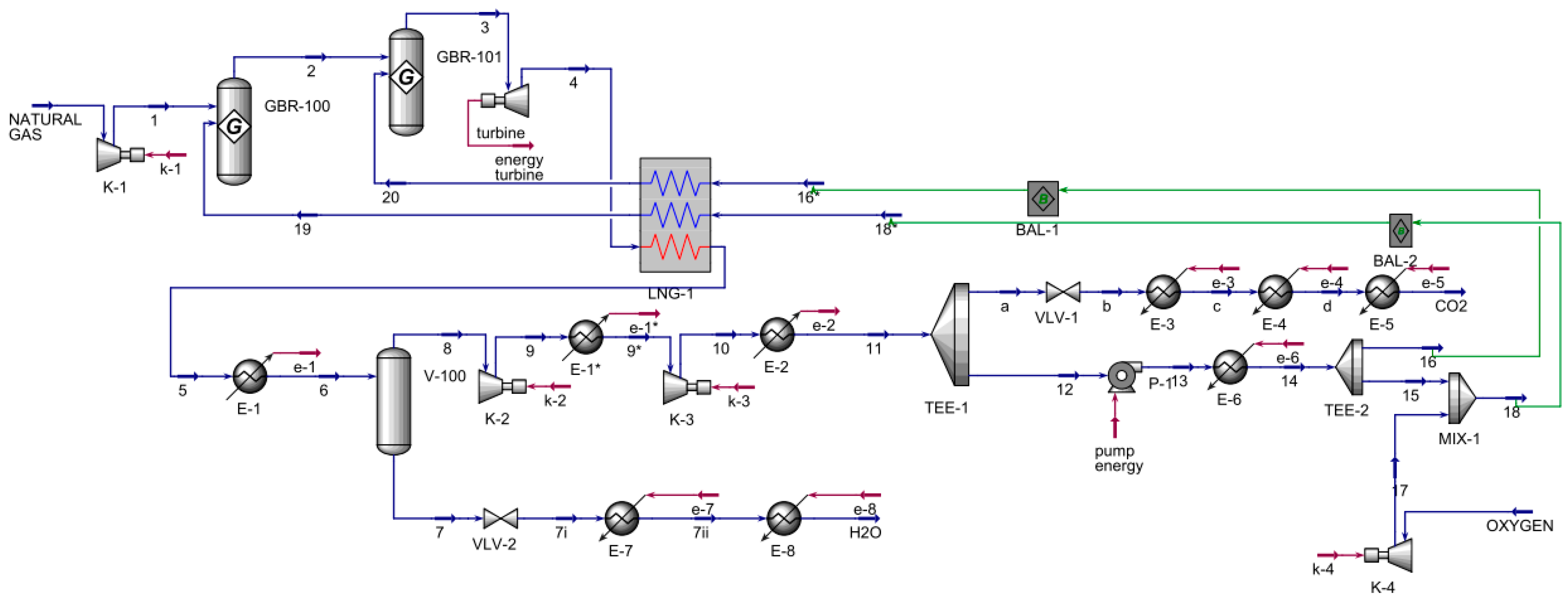
The Allam–Fetvedt cycle for power generation simulation (
Figure 2) contained two major inputs and two outputs. First, natural gas was compressed as allowed in two Gibbs reactors; next, the stream entered an expander, which served as the turbine for power generation. The stream was then cooled in a multi-stream heat exchanger, also known as an LNG heat exchanger in Aspen HYSYS, and allowed to cool further before entering a separator to remove the water from the stream. The pressure of the water stream was decreased through a valve before being heated in two heaters in sequence to reach the vapor phase. The other stream from the separator, 8, was compressed in two series compressors and cooled before splitting. The main component of this stream was carbon dioxide; a portion was an output of the process, as shown in the flowsheet as a stream to CO
2, while the other portion was recycled in the process, where it was fed to a pump, heated, and divided. Stream 16 was sent to the multi-stream heat exchanger, while stream 15 was mixed with the compressed oxygen stream, 17, and the resulting mixed stream, 18, was routed to the same heat exchanger. The outlets of multi-stream heat exchanger streams 19 and 20 were inlets to the first and second Gibbs reactors, respectively. The main inlets and outlets are presented in
Table 1.
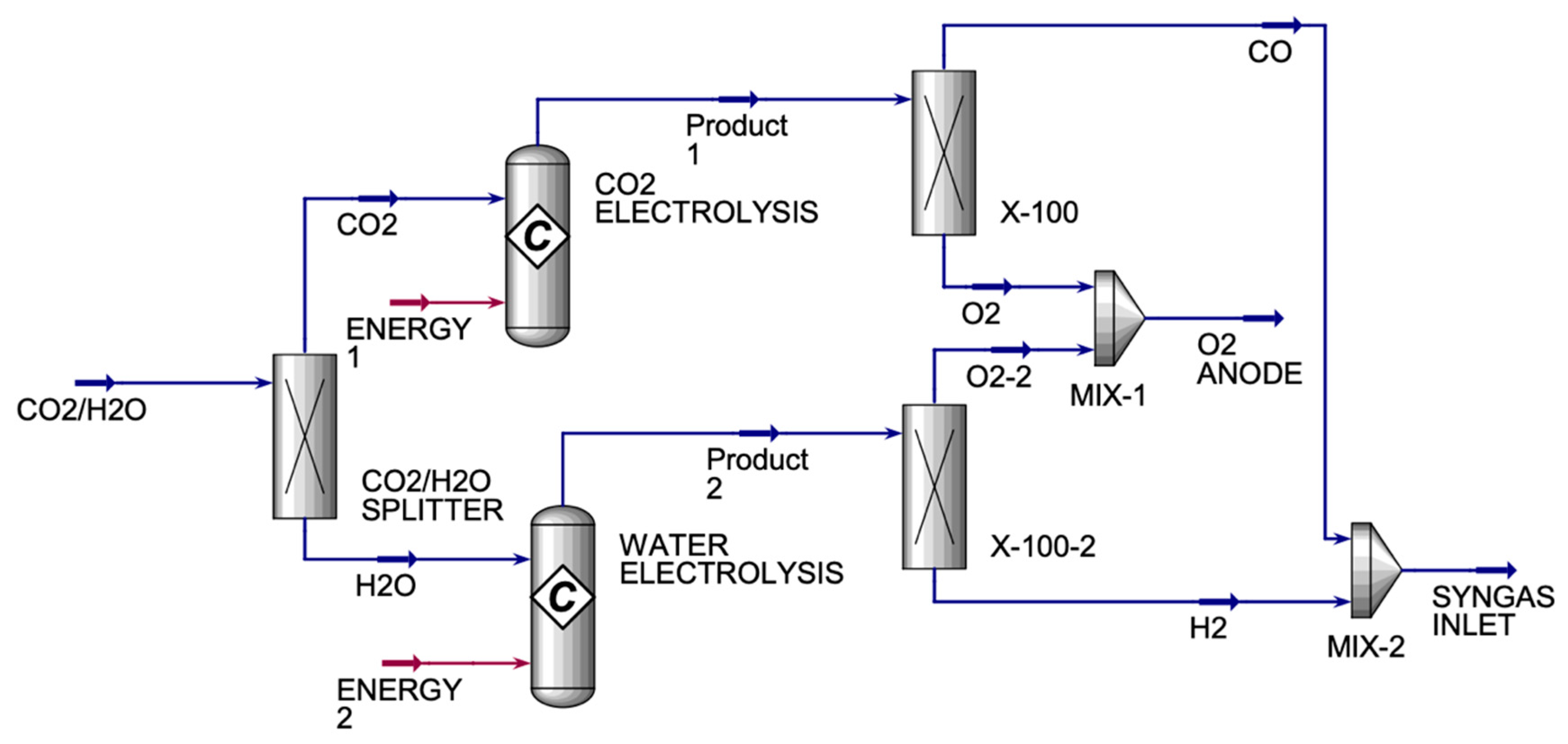
The CO
2/H
2O electrolyzer (
Figure 3) had one inlet and two exit streams. The CO
2/H
2O electrolyzer’s incoming stream was made up of CO
2 and H
2O streams that were divided into a component splitter to produce pure CO
2 and H
2O streams. Each pure stream entered a conversion reactor. The CO
2 conversion reactor generated a product stream of CO and O
2, which was divided in a component splitter to create pure CO and O
2 streams. The X-100 and X-100-2 were component splitters that were used to split the components into desired fractions between the two streams. They were used because the product streams from both conversion reactors had oxygen in them, which was not wanted in the SYNGAS stream. Therefore, X-100 was used to split the oxygen completely from carbon monoxide, where oxygen was sent to MIX-1, and carbon monoxide was sent to MIX-2. X-100-2 was used to split the oxygen completely from hydrogen, where the oxygen was sent to MIX-1 to be mixed with the oxygen from X-100, and hydrogen was sent to MIX-2 to be mixed with carbon monoxide from X-100 to form SYNGAS. Under optimal operating conditions, SOEs can deliver hydrogen purity levels of 99.9% or higher, assuming good sealing and system integrity. Therefore, in this study, we achieved a hydrogen purity of approximately 100%.
Table 2 displays the main inlet and outlet streams for the HO and CO co-electrolyzers.
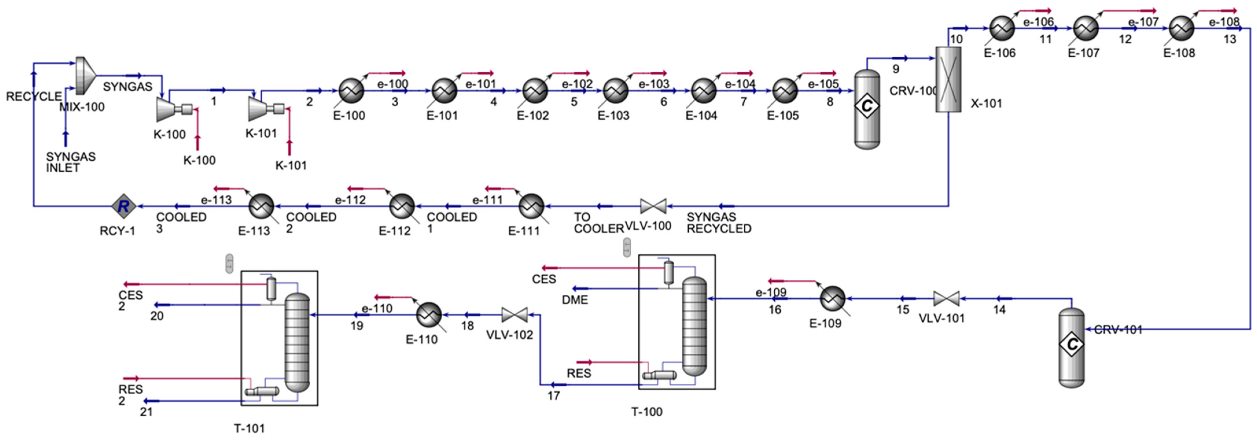
The DME process (
Figure 4) contained one inlet and three outlet streams. The process mixed the syngas from the CO/HO electrolyzer with a recycled syngas stream. The syngas was compressed in a series of compressors and was allowed to cool in a series of coolers; then, it was sent to a methanol reactor and a conversion reactor. Stream 9, which contained mainly methanol and unreacted syngas, was allowed to split to form a pure methanol stream 10 and a stream of unreacted syngas, which was then cooled in a series of coolers to be recycled. The pure methanol stream was cooled in a series of coolers, which was then sent to the DME conversion reactor, forming stream 14, which contained DME and H
2O. Its pressure decreased in the valve, and it was cooled before being sent to the distillation column to enhance the purity of the DME stream. The top product of the distillation column was mainly DME, and the bottom contained mainly H
2O and some traces of methanol, which were sent to a valve, then a cooler, and then to the final distillation column.
Table 3 shows the main inlet and outlet streams for the DME production unit.
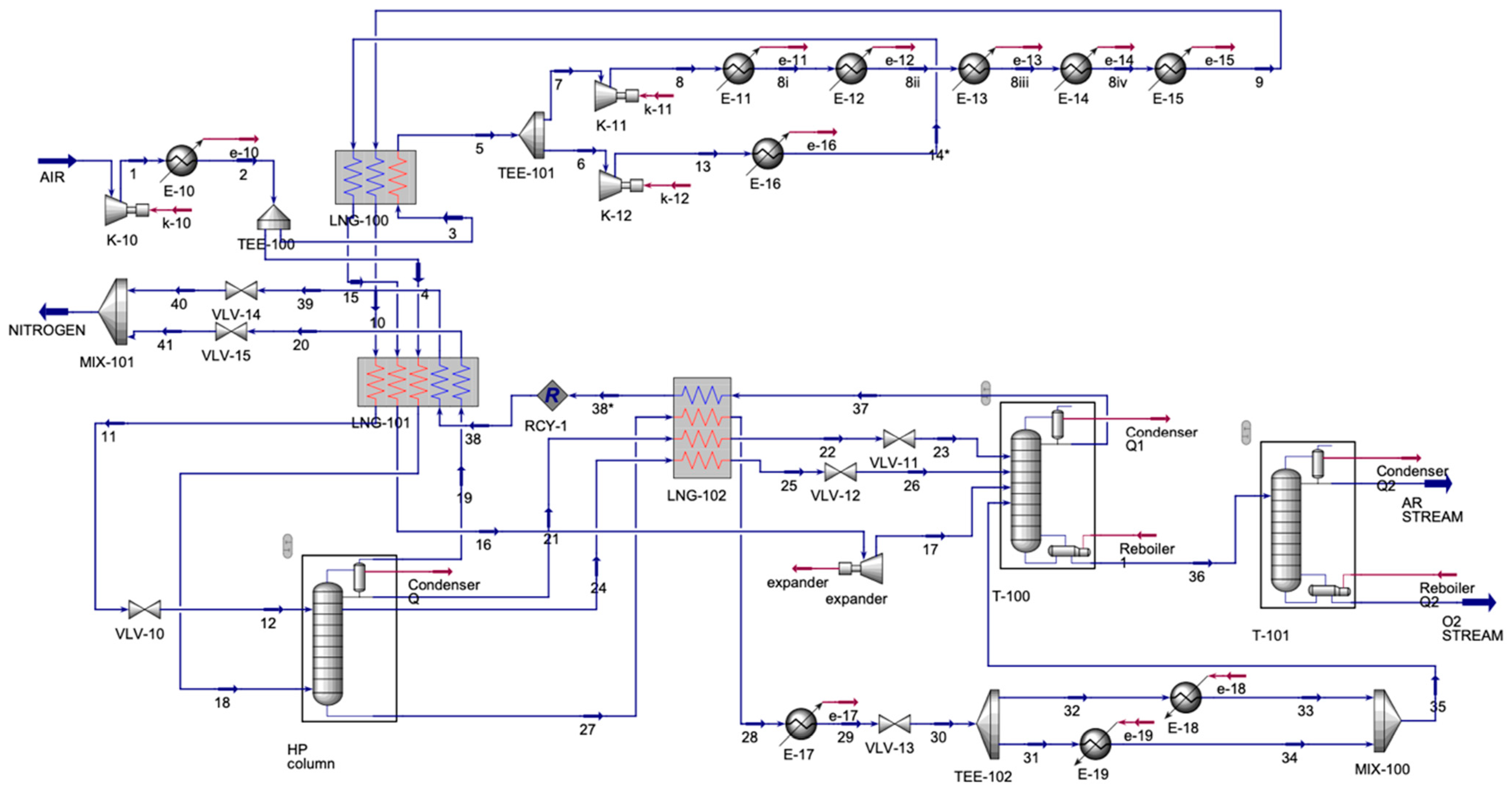
The ASU process (
Figure 5) contained one inlet stream and three outlet streams. The air inlet was compressed and then was cooled. The cooled stream split; each stream entered a multi-stream heat exchanger, LNG-100 and LNG-101. For LNG-100, the output stream, 5, was split again, and stream 6 was compressed and then cooled. The cooled stream was input into LNG-100. Stream 7 was compressed and also cooled. However, this was performed in a series of coolers, with another input to the LNG-100. Streams 10 and 15, the outputs from LNG-100, and the split stream, 4, were inputs to LNG-101. Output stream 11 entered the valve to decrease the pressure and then was sent to the absorber along with stream 18, an output from LNG-101. The absorber had four output streams, one of which was stream 19, which was an inlet to LNG-101; the other three streams, 21, 24, and 27, were input streams for LNG-102. Stream 16, another output from LNG-101, was compressed and then was allowed to enter a distillation column (T-100). Stream 28 from LNG-102 was cooled and then was sent to a valve to decrease the stream’s pressure. Then, the stream was split for heating and then was mixed to be sent to T-100 as stream 35. Streams 22 and 25 were sent to the valve, and then they were sent to T-100. Output streams from T-100 were 37 and 36. Stream 37 was an inlet for LNG-102, forming stream 38*, which was recycled to LNG-101. In LNG-101, streams 39 and 20 were sent to the valve and were allowed to mix to form a nitrogen stream. Stream 36 from T-100 was sent to the final distillation column (T-101), forming argon (Ar) and oxygen (O
2).
Table 4 displays the main inlet and outlet streams of the ASU.
4. Results and Discussion
Developing innovative technologies or enhancing existing processes in alignment with sustainability standards while incorporating alternative products like methanol and DME is crucial for producing clean and cost-effective energy and chemicals while addressing economic and energy-related challenges. However, achieving sustainable industrial processes remains a major global challenge for the chemical industry. Embedding sustainability principles into process design is essential for overcoming this hurdle by minimizing or eliminating adverse environmental effects. Methodological sustainability assessment serves as a valuable tool at any process scale, enabling designers to conduct a comprehensive performance evaluation. Key sustainability indicators include economic viability, energy efficiency, environmental impact, and material utilization, all of which are essential for assessing overall sustainable performance.
Material Utilization Efficiency
As can be seen in
Table 5, the proposed integrated process effectively utilized various feedstocks, including natural gas, air, and water, to maximize the co-production of power, hydrogen, and dimethyl ether (DME). The material utilization efficiency of the system can be evaluated by examining the input and output streams of each section.
The CO2 looping ratio in the Allam–Fetvedt cycle is an important metric that determines how much CO2 is recycled within the system, compared to the amount emitted or utilized in downstream processes. Since the cycle operates as a closed-loop supercritical CO2 power generation system, a significant portion of the CO2 remains in circulation while a controlled amount is extracted for external use. In the Allam–Fetvedt cycle, the ideal looping ratio approaches 1 (100%), meaning that nearly all CO2 is recirculated. However, practical designs operate with a CO2 looping ratio of 0.9–0.98 due to minor leakage, purging, and system inefficiencies. In this study, the achieved looping ratio was 0.96 by having 263,056 kg/h of CO2 extracted for further process steps. When we considered the 330 days of plant operation, this led to productions of 189,435.47 MT per annum (H2), 980,021 MT per annum (DME), and 7,698.27 MT per annum (methanol). Dimethyl ether (DME) production facilities vary in capacity, ranging from small-scale plants to large industrial complexes. Large-scale facilities can produce up to 800,000 metric tons of DME per year. In the proposed design, 10% excess O2 was produced. Only 1.8% of the water was needed to be fed externally, but by reducing the production capacity by the same percentage, the external water can be eliminated.
Energy Efficiency
The Allam–Fetvedt cycle achieves efficiency levels comparable to or exceeding traditional combined cycle gas turbines (CCGTs) while capturing CO2 at no additional energy penalty. Its combination of high efficiency and carbon capture makes it a promising future energy technology for net-zero power generation. Its theoretical efficiency ranges between 59–61%, and its practical efficiency ranges between 55–57%. This study reported the total and net power generations by the cycle as 7.95 × 10⁵ kW (2.862 × 10⁹ kJ/h) and 4.37 × 10⁵ (1.5732 × 10⁹ kJ/h) kW, respectively. The efficiency was 55%.
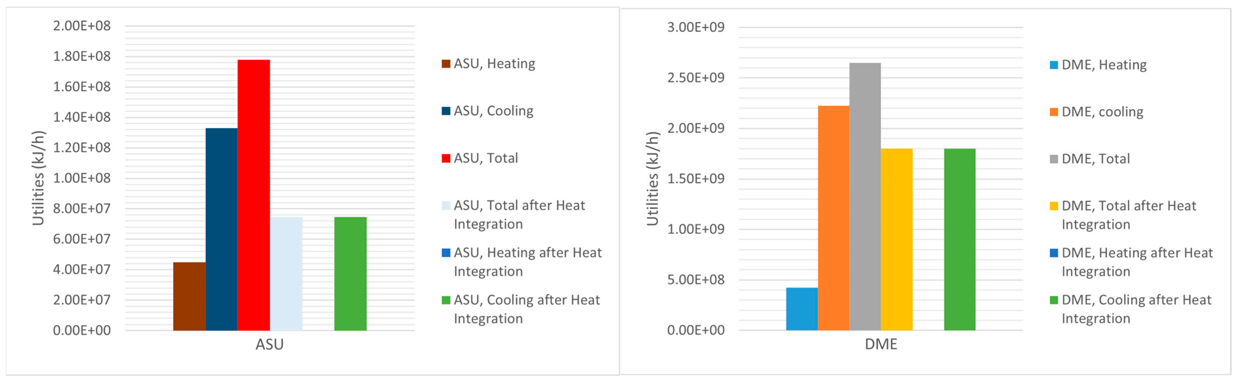
Figure 6 depicts the utilities of ASU and DME production units in both situations, before and after heat integration and optimization. For the simulation of the co-electrolysis of H
2O and CO
2, the required energy for the single cell, which produced 4.8 kmol/h of H
2, 2.4 kmol/h of CO and 36 kmol/h of O
2, was 1.855 × 10
6 kJ/h. However. the production of 191,500 kg/h (17,930 kmol/h) of syngas required 4.61 × 10
9 kJ/h, and with a cell efficiency of 85%, the total energy requirement for the electrolyzer system became 5.43 × 10
9 kJ/h (causing 65% of the process’s energy requirement).
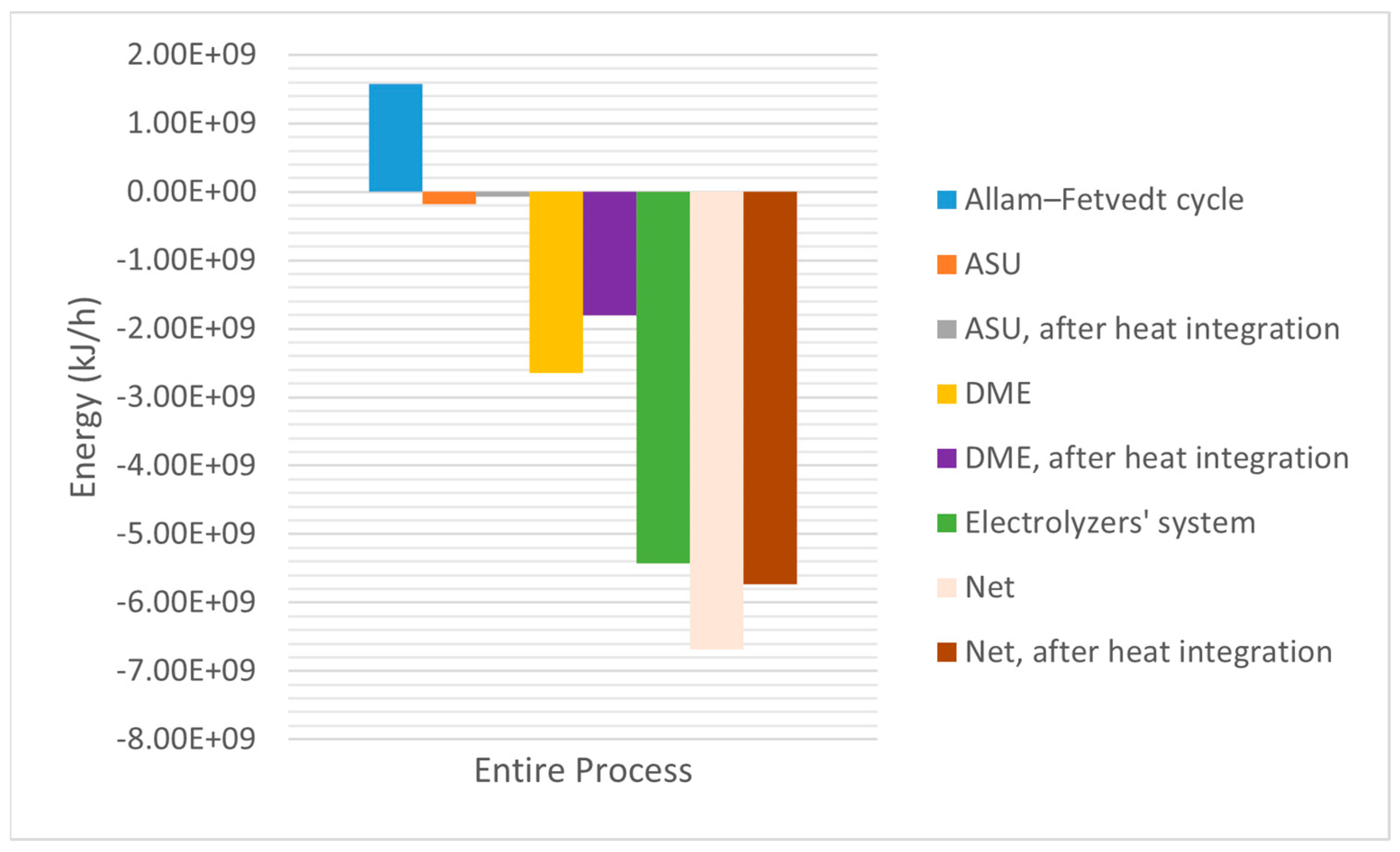
Figure 7 shows that the process’s net energy requirements were 6.68 × 10
9 kJ/h and 5.73 × 10
9 kJ/h (after the heat integration). Heat integration enhanced the process’s energy efficiency by 14.22%. Despite the use of high-energy electrolyzer systems (81.28% of the net energy requirement), the proposed integrated process’s net energy requirement was competitive with that of the existing conventional high-emission release processes.
Environmental Impact
Net zero implies balancing the amount of greenhouse gases (GHGs) released into the atmosphere with an equivalent amount being removed, essentially nullifying industrial carbon footprints. The transition to a net-zero economy, particularly in energy-intensive industries, is a critical goal for mitigating climate change. Advanced hybrid technologies play a pivotal role in enabling industries to meet their net-zero targets by combining various innovations to enhance efficiency, reduce emissions, and transform industrial processes. They enable industries to transition from carbon-intensive processes to more sustainable, resilient, and energy-efficient operations. As industries face increasing pressure to meet climate targets, the role of hybrid technologies in enabling this transformation will only grow in importance [
28,
29].
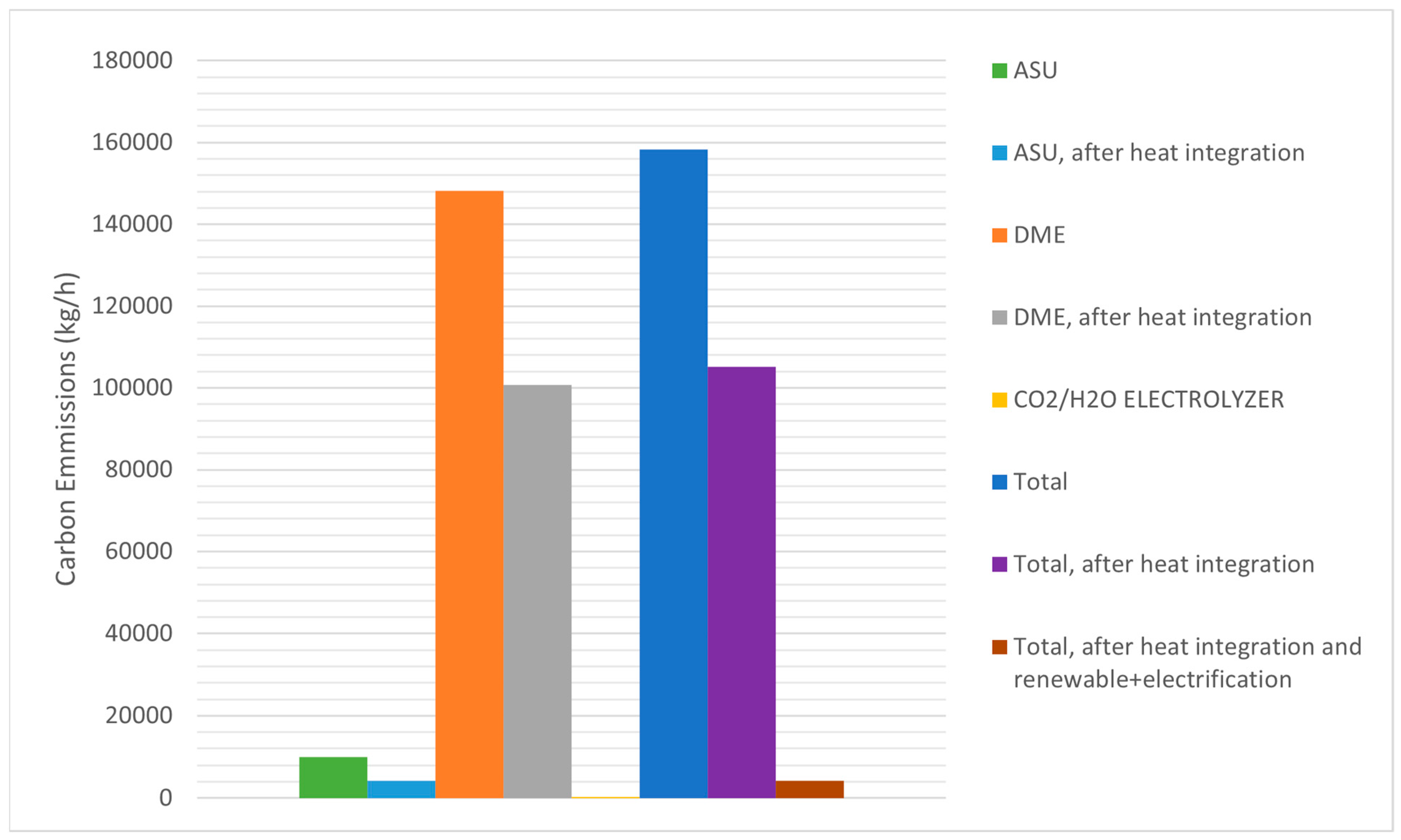
In this study, the proposed process integration of the CO
2 capture rate in the Allam–Fetvedt cycle achieved 96%, and the rest of the produced CO
2 (263,056 kg/h of CO
2) was extracted for further process steps. Therefore, the Allam–Fetvedt cycle operated as net-zero. The carbon emissions associated with dimethyl ether (DME) production vary significantly based on the production pathway, feedstock, and energy sources utilized. Literature reports DME production carbon emissions ranges between ≈0.21 (green hydrogen-based DME production) to 4.4 (fossil fuel-based DME production) kg CO
2 per kg of DME produced [
30,
31]. As can be seen in
Figure 8, in this study, the calculated carbon emissions were 1.16 and 0.77 kg CO
2 per kg of DME produced before and after heat integration, respectively. Therefore, this range is significantly lower than the reported emissions from fossil fuel-based DME production. However, by applying various strategies, such as utilizing renewable (solar and wind) energy in a co-electrolyzer system and electrification of the ASU and DME production units, carbon emissions can be reduced to near zero (
Figure 8). Thus, as depicted in
Figure 8, the proposed process can be operated at near-zero (0.0308 kg CO
2 per kg of DME produced) values after applying the integration of renewable energy and electrification strategies.
Economic Viability
The development of the proposed integrated process for the co-production of power, hydrogen, and DME using an electrolyzer presents a promising pathway toward sustainable energy and chemical production. However, to ensure its feasibility for large-scale implementation, a detailed techno-economic analysis (TEA) is essential. This forthcoming study will conduct a comprehensive evaluation of both technical and economic aspects, identifying key performance indicators, cost drivers, and economic viability factors.
5. Conclusions
This study presents a comprehensive design and simulation of an integrated process for the co-production of power, hydrogen, and dimethyl ether (DME), utilizing the high-efficiency Allam–Fetvedt cycle in conjunction with a solid oxide electrolyzer system for CO2 and H2O co-electrolysis. The proposed system effectively links carbon capture, green hydrogen production, and sustainable fuel synthesis within a single energy-efficient and environmentally conscious framework. The key findings of this study can be summarized as follows: (1) The Allam–Fetvedt cycle demonstrated a net electrical efficiency of 55%, and the results demonstrated that 96% of CO2 was recycled within the Allam–Fetvedt cycle, with the rest (the 4% of CO2) being captured and converted to syngas, validating its potential as a net-zero-emissions power generation technology. (2) The solid oxide co-electrolyzer system was shown to operate with an overall energy efficiency of 85%, consuming approximately 5.43 × 10⁹ kJ/h to generate 191,500 kg/h of syngas, which was further utilized for downstream DME production. Despite the high energy needs of the electrolyzer system (81.28% of net energy), the overall energy requirement remained competitive with conventional methods. (3) Through process heat integration, the total system energy requirement was reduced by 14.22%, from 6.68 × 10⁹ kJ/h to 5.73 × 10⁹ kJ/h, highlighting the critical role of integration strategies in improving overall energy performance. (4) The process produced 980,021 metric tons of DME annually, with associated carbon emissions reduced from 1.16 to 0.77 kg CO2/kg DME after heat recovery. Moreover, by incorporating renewable energy sources, emissions could be reduced to 0.0308 kg CO2/kg DME, approaching true net-zero operation. (5) The material utilization analysis showed that nearly 98.2% of the water demand was internally recovered, and only 1.8% required external input, indicating strong circularity and resource efficiency within the process. This research makes a significant contribution by demonstrating a viable pathway for the low-carbon, high-efficiency co-production of energy and chemicals. The integration of the Allam–Fetvedt cycle with SOE-based syngas generation and DME synthesis enables a highly compact and efficient process configuration, addressing several of the sustainability challenges associated with conventional fossil-based systems. Furthermore, the selection of indirect DME synthesis allows for higher selectivity and process controllability, which are essential for scalability and commercialization. Practical implications of this work include the potential application of this integrated process in natural gas-rich regions aiming to decarbonize their energy and chemical sectors. The system’s modularity and compatibility with renewable energy inputs also position it well for integration with solar or wind resources, supporting flexible and resilient energy infrastructures. Looking ahead, future research will focus on conducting a detailed techno-economic analysis (TEA) and life cycle assessment (LCA) to evaluate the system’s competitiveness and long-term environmental impact. Additionally, further investigation into dynamic operational strategies, advanced control systems, and scaling effects will be essential for real-world implementation. These steps will be crucial in advancing this concept from simulation to pilot and eventually full-scale industrial deployment, contributing meaningfully to the global energy transition.


