Article

Cooperative Optimization Analysis of Variable-Speed and Fixed-Speed Pumped-Storage Units Under Large Disturbances in the Power System

School of Electrical Engineering, Shenyang University of Technology, Shenyang 110870, China
*
Author to whom correspondence should be addressed.
Energies 2025, 18(10), 2441; https://doi.org/10.3390/en18102441
Submission received: 31 March 2025 / Revised: 29 April 2025 / Accepted: 9 May 2025 / Published: 9 May 2025

Abstract

:
Aimed at the large disturbance of a power system caused by frequent new energy clusters going off-grid, we propose a cooperative optimization strategy of variable-speed and constant-speed pumped-storage units to address power oscillation due to significant power shortages following the clusters going off-grid. From a multi-time-scale perspective, we first investigate the fast power support control strategy of variable-speed pumped-storage (VSPS) units during new energy cluster off-grid scenarios. Using a consensus algorithm, the VSPS acts as the primary unit, while the constant-speed unit provides long-term power support. We present a rapid power control method for VSPS to prioritize frequency stability in mainland grids with high new energy penetration. This ensures stable power support for large-scale new energy clusters under large disturbances across multiple time scales. Simulation analysis on a high proportion of new energy power networks with new energy clusters confirms the effectiveness of our proposed method.

1. Introduction

With the growing global demand for renewable energy, large-scale and large-capacity new energy clusters, as an important part of clean energy, are gradually becoming a hot spot in the energy field [1,2]. Large-capacity new energy clusters are generally at the end of the power grid. Under extreme working conditions such as off-grid new energy clusters, large power losses will occur, making it difficult for the system to support the safe and stable operation of the power network. There has been a major power outage caused by a large-scale power shortage of wind power in Brazil [3]. The power grid blackout in some parts of England and Wales caused by Horne’s new off-grid energy disturbance source [4,5] urgently needs to improve the stability of the onshore power system if the large-scale new energy system at the end of the grid is off-grid. Pumped storage units are one of the best ways to supplement the power gap.
Most new energy unit groups are located at the end of the power grid, and most wind power and photovoltaic systems are connected to the main network through a 500 kV line after they are gathered at the gathering station. If an outgoing line failure occurs, there will be an active power gap of more than 1000 MW in the grid, and a frequency drop problem will occur. The traditional method generally adopts a low-frequency cutting pump. If the new energy unit offline failure has not been solved, it may cause a low-frequency load reduction, which seriously affects the overall stability of the system. VSPS can quickly supplement large amounts of power, which can avoid the above problems.
A pumped-storage power station has the functions of peak regulation, valley filling, frequency modulation, and emergency backup, which is the main method of large-capacity electric energy storage at present, and the most effective means to solve large power shortages in the current and future period of a power system. At present, traditional constant-speed and constant frequency pumped-storage units in pumped-storage power stations are increasing in operation and construction, where the power cannot be adjusted quickly and smoothly while the pump is running. In recent years, variable-speed pump storage technology has developed rapidly, and the variable-speed constant frequency operation of large pumped-storage units under pump conditions can be realized through rotor AC excitation, which makes the VSPS have better operating performance than traditional constant-speed pumped-storage units [6]. Currently, the VSPS group is generally built at the same time as the VSPS and constant-speed pumped-storage unit, which will form a pumped-storage unit group. However, there is little research on the coordinated operation of pumped-storage units and the power response and stability of pumped-storage units under a power oscillation caused by off-grid new energy.
The existing research on variable-speed pumped-storage units (VSPS) is extensive. The literature [7] explores the speed callback control and adaptive strategy of doubly-fed VSPS from a speed perspective. The unbalanced rotor protection of VSPS based on fault components is studied in the literature [8]. The literature [9,10] focus on quantifying the power regulation characteristics of variable-speed pumped-storage units under pump mode and the operational issues of variable-speed pumped-storage power stations. The literature [11] investigates the dynamic regulation characteristics of VSPS to mitigate wind power fluctuations caused by wind turbine operations. The literature [12] studies the hydraulic characteristics’ influence on VSPS under pump mode, while the literature [13] analyzes the stability of VSPS under rapid control strategies. The literature [14] enhances the starting strategy of a double-fed induction motor with high feed-rated VSPS in pumping mode. The literature [15] delves into the hydraulic disturbance characteristics and power control of variable-speed pumped-storage power stations with a power generation mode. The literature [16,17] examine the dynamic optimization operation of variable-speed pumped-storage power stations and the short-circuit starting strategy of the rotor of pumped-storage units with high-rated variable-speed feeds. These studies primarily center on the control and stability analysis of VSPS itself. The literature [18] analyzes the balance capacity of double-fed speed-regulating pumped-storage units under remote power grid faults. The literature [19] optimizes the control strategy of small-signal oscillation stability analysis for a grid-connected system of VSPS under multiple time scales. The literature [20] explores the power regulation and exchanges strategies between variable-speed pumped-storage units and local power grids. The literature [21] analyzes how to improve the transient stability of VSPS in multi-node power grids, and the literature [22] examines the frequency modulation capacity of VSPS. These studies demonstrate that VSPS can effectively regulate system power through electromagnetic and mechanical power control, thereby supporting the stable operation of power networks [23,24,25,26]. However, there is still room for further exploration of VSPS application in enhancing power system stability under large disturbances and high renewable integration scenarios. Recent studies have made significant contributions to the operation and control of energy hubs. The literature [27] proposed a synergistic operation framework for energy hubs, combining stochastic distributionally robust chance-constrained optimization with Stackelberg games. The literature [28] investigated the distributed hybrid-triggered observer-based secondary control of multi-bus DC microgrids over directed networks. Reference [28] developed an integrated model for optimal operation in an energy hub by merging distributionally robust optimization with Stackelberg games. These works provide valuable insights into enhancing the stability and efficiency of energy systems.
However, most of the existing studies focus on the active power and reactive power characteristics of VSPS and constant-speed pumped-storage units, but there is no research on the multi-time scale power coordination of VSPS and constant-speed pumped-storage units at the end of the power system and under the condition of off-grid new energy clusters. In this paper, the focus is on the cooperative optimization strategy of variable-speed and constant-speed pumped-storage units in power systems subject to large disturbances, particularly those caused by the frequent off-grid of new energy clusters. The research explores how these units can work together to address power oscillation issues resulting from significant power shortages when new energy clusters go off-grid.
From the perspective of multiple time scales, the paper first delves into the fast power support control strategy of variable-speed pumped-storage units (VSPS) when new energy clusters are off-grid. Using a consistency algorithm, the VSPS is designated as the main unit, while the constant-speed pumped-storage unit serves as the secondary unit for long-term power support. The study proposes a rapid power control method for VSPS to prioritize frequency stability in land-based grids with high proportions of new energy. This approach aims to provide stable power support for large-scale new energy clusters under large disturbance conditions across multiple time scales.
The simulation analysis is based on a power network with a high proportion of new energy that includes new energy clusters. The results of the simulation effectively confirm the validity of the proposed method.
The key innovations of this paper are as follows:
  • This paper delves into the strategy for VSPS to supply large-scale fast power to power systems when new energy is off-grid. Through a practical-case analysis, it thoroughly explores the full-range characteristics of variable-speed pumped-storage.
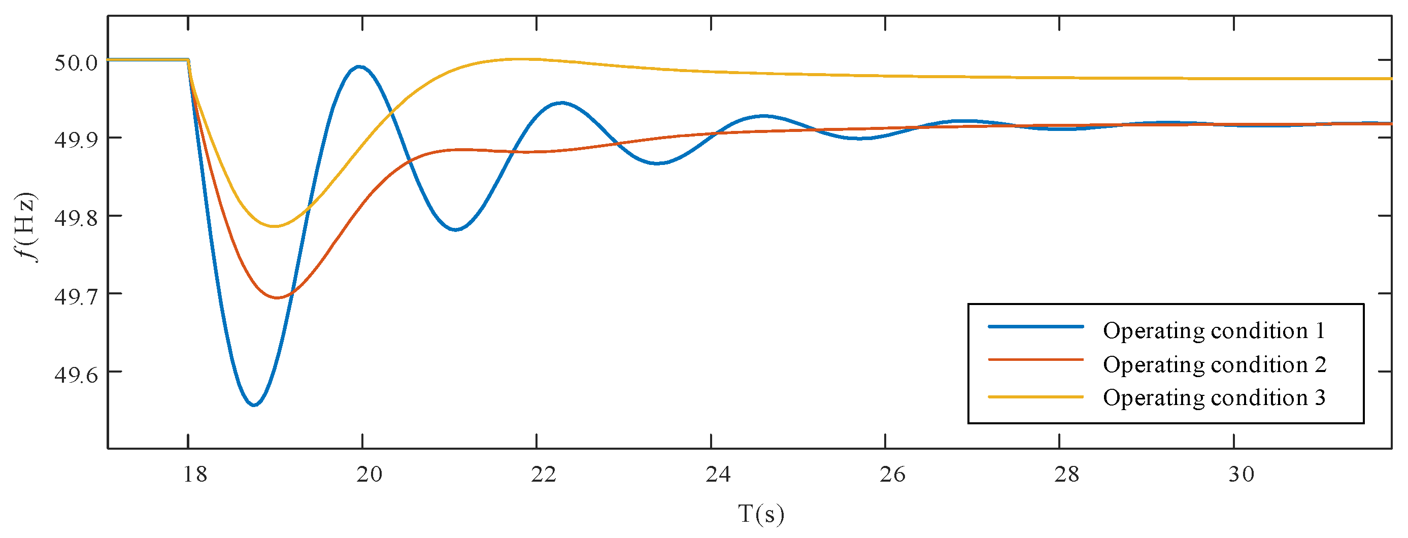
  • A collaborative optimization strategy for pumped-storage clusters, based on the consistency algorithm and applicable during large power-system disturbances, is proposed and its stability is analyzed. This strategy improves the stability of power systems with a high proportion of new energy clusters after they are off-grid from multiple time-scale perspectives. Specifically, it enhances the recovery frequency of large-disturbance faults, elevating it from 49.56 Hz to 49.8 Hz.
This paper is organized as follows.
The second part analyzes the frequency drop characteristics of large disturbances in the power system, the large power fast control strategy of variable-speed pumping and storage units, and the power control strategy of constant-speed pumping and storage units. The third part analyzes the cooperative optimization strategy of variable-speed and constant-speed pumped-storage units based on the consistency algorithm from the perspective of a time series analysis. The fourth part tests the proposed method based on the large disturbance caused by a certain wind power cluster offline. In this study, a ‘large disturbance’ is defined as a power perturbation exceeding 500 MW or an event causing a frequency drop of more than 0.5 Hz.

2. Power Control Principle Analysis

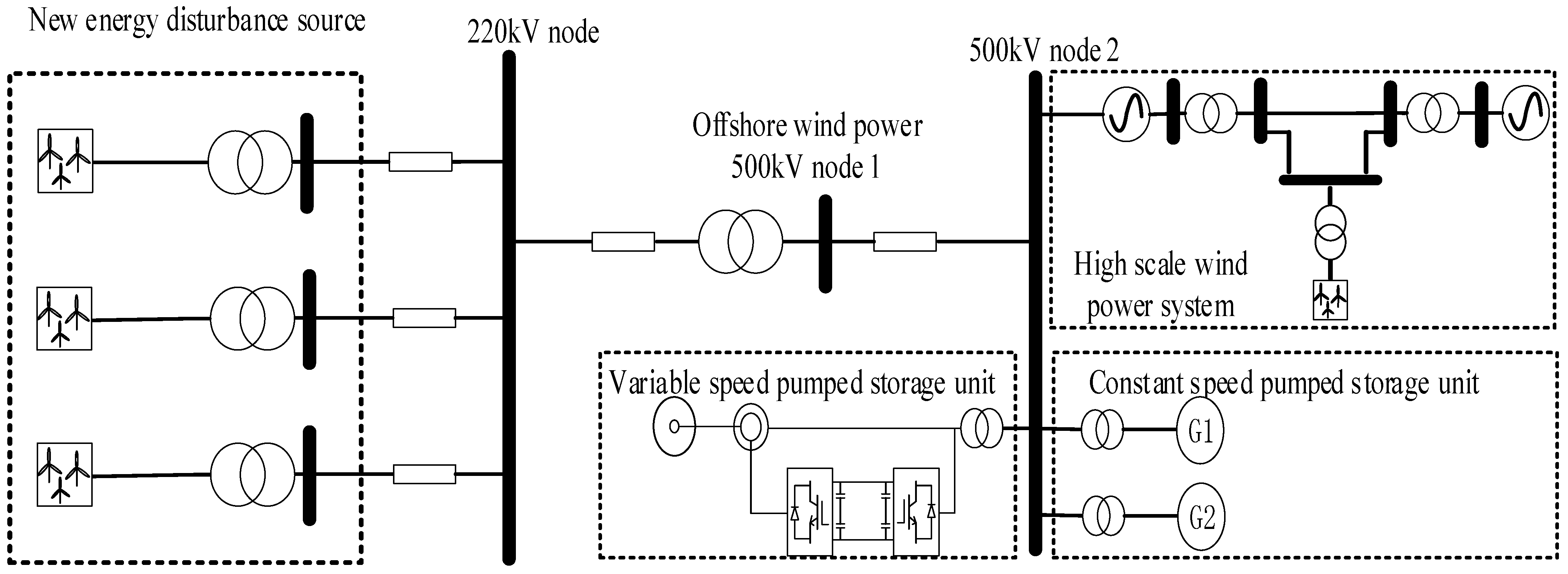
2.1. Frequency Drop Characteristics of New Energy Disturbance Source When Off-Grid

On the second time scale, the frequency dynamic response of the system after a large power disturbance is divided into three stages: disturbance power distribution, inertia response, and primary frequency modulation. In the disturbance power distribution stage, the adjustable unit shares the disturbance power according to the electrical distance between it and the fault point. The energy in the inertia response stage comes from the kinetic energy of the rotor of the unit, and the response time scale is in milliseconds, which can gain time for a frequency modulation action. Based on the frequency dynamic response process and the rotor motion equation, the frequency response satisfies the formula at any time.
T J d ω ω 0 d t + D ω ω 0 = P m P e .
T J = i = 1 n S B i T J i i = 1 n S B i .
D = i = 1 n S B i D i i = 1 n S B i .
where SBi is the rated capacity of the i generator, TJi is the inertia time constant of the i generator, Di is the damping coefficient of the i generator, ω is the system speed, ω0 is the initial value of the system speed, and f is the system frequency. Pm is the mechanical power of the synchronous unit, Pe is the electromagnetic power of the synchronous unit. J is the system moment of inertia.
The parameters are linearized, and the disturbance power of the new energy disturbance source grid-connected system is set as ΔPW.
T J d Δ f d t + D Δ f = Δ P m + Δ P W Δ P L .
Δ P e = Δ P L Δ P W .
ΔPm is the mechanical power change of the unit providing frequency modulation energy, ΔPe is the electromagnetic power change of the unit providing frequency modulation energy, and ΔPL is the system load damping.

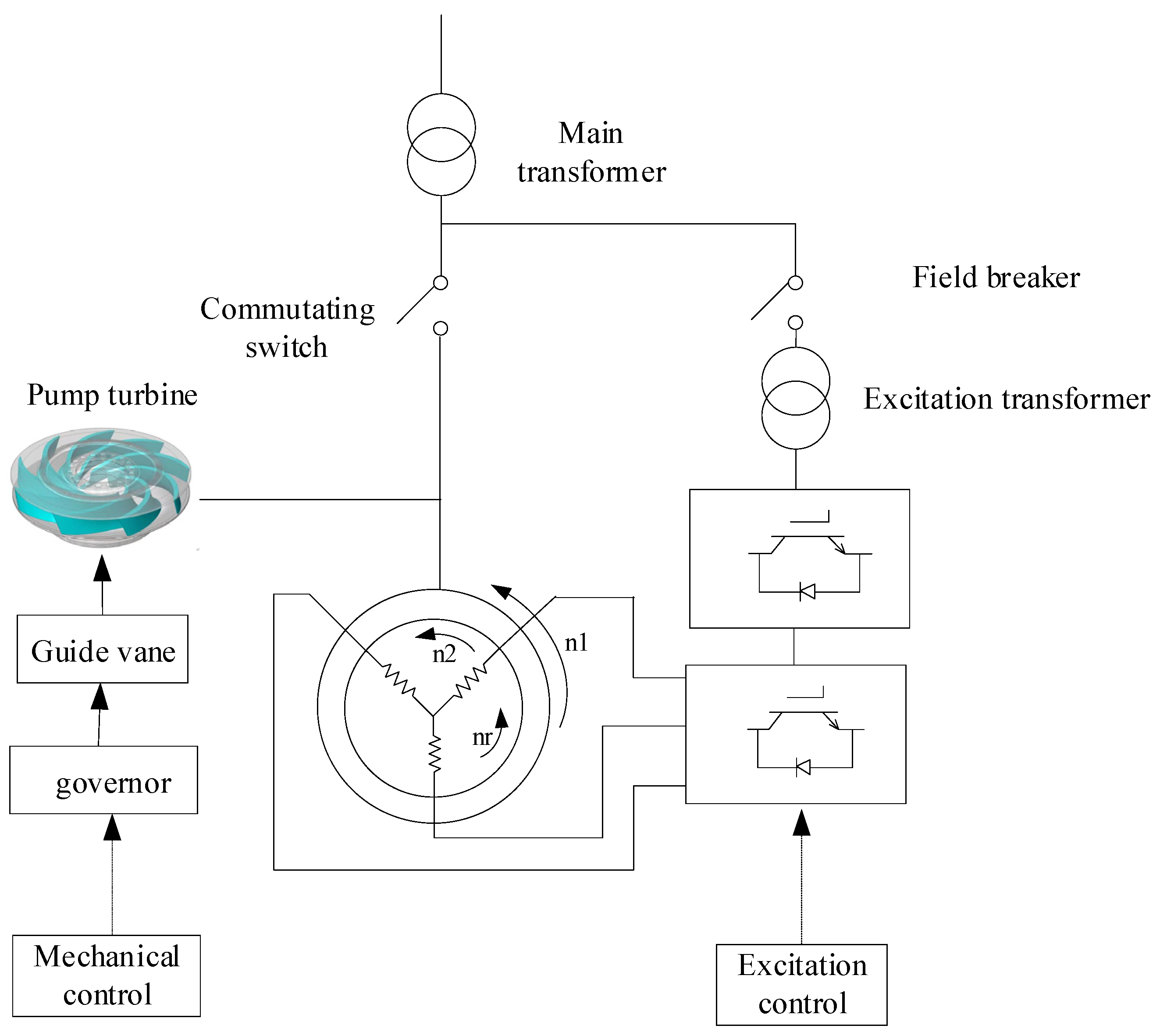
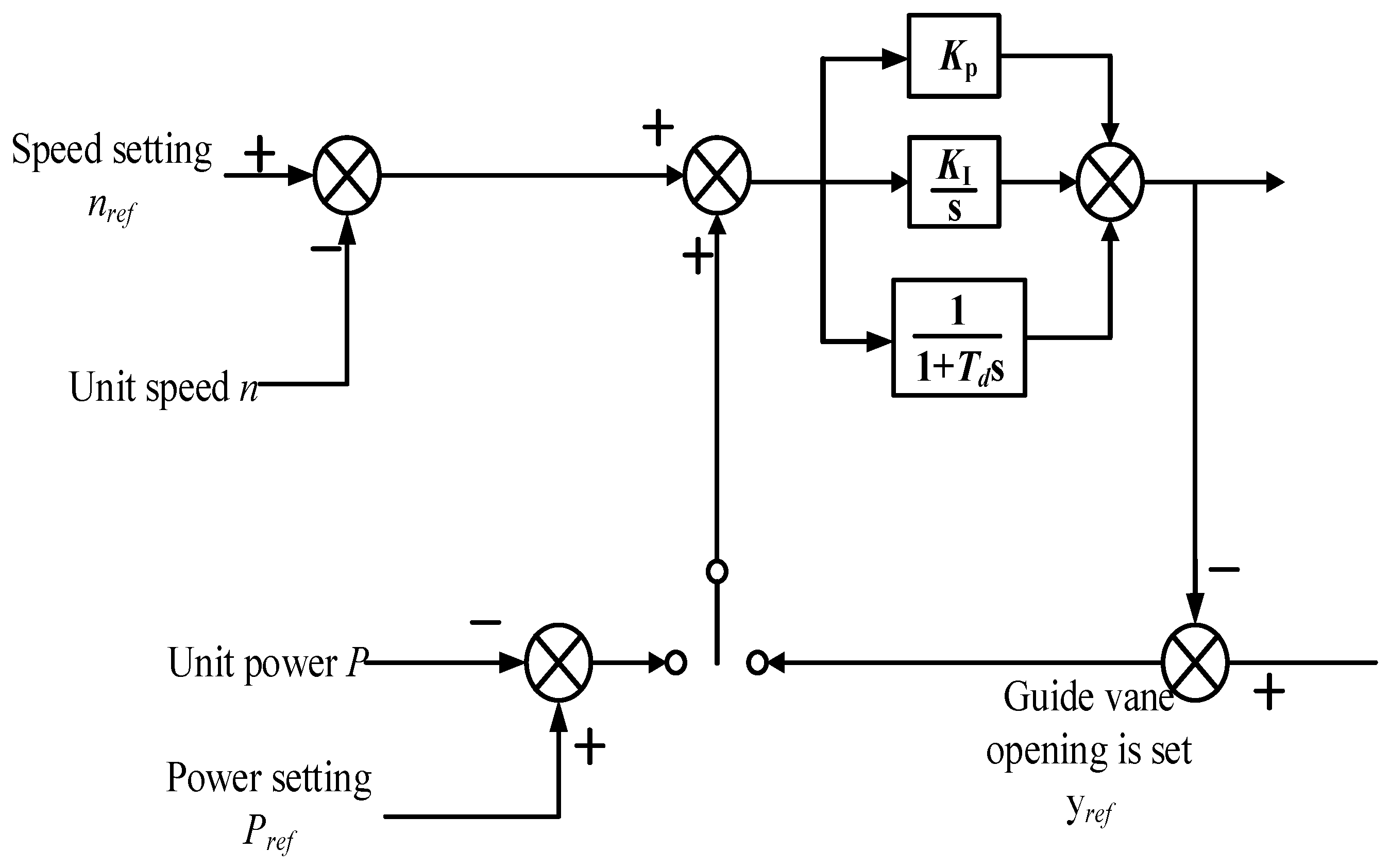
2.2. Rapid Control Strategy of Large Power of Variable-Speed Pumping and Storage Unit

The control of variable-speed pumping and storage includes two parts: mechanical torque control and electromagnetic torque control. Figure 1 shows the topology of a doubly-fed variable-speed pumped-storage unit. The mechanical torque control includes the governor control based on mechanical power control, the direct control of the guide vane control to the pump-turbine, and the electromagnetic torque control that is mainly realized by the AC excitation converter. Divided into a grid side converter and a motor side converter, the grid side converter control network side converter’s function is to maintain the stability of DC link voltage. The motor side converter controls the core of the unit control, which can provide excitation for the generator rotor, realize the rotor speed tracking, and realize the decoupling control of active power and reactive power, frequency response control, and other functions.
In the grid-side converter, because the voltage of the grid remains unchanged, the directional vector control technology based on the grid voltage is adopted. The converter model under three-phase static coordinates is converted to a two-phase rotating coordinate system, and the three-phase current on the AC side is converted to the current component under the dq coordinate system, and the decoupling control is carried out to obtain id and iq:
u d r = L d i d d t + R i d + ω 1 L i d + u s u q r = L d i q d t + R i q ω 1 L i q .
id and iq are the current components of the d and q axis in a two-phase rotating coordinate system. udr and uqr are the transformer outputs of the d, q axis voltage component. In the motor side converter control, the variable-speed extraction and storage motor adopts the stator voltage orientation control method in the synchronous dq axis coordinate system.
To realize the power decoupling control of VSPS, the active and reactive power of VSPS are listed:
P s = u s d i s d + u s q i s q Q s = u s q i s d u s d i s q .
Using the vector control strategy based on stator voltage orientation and ignoring the stator resistance at power frequency, it can be simplified as follows:
P s = U s i s d = L m L s U s i r d Q s = U s i s q = U s 2 L s ω s + L m U s L s i r q .
It can be seen from the above formula that the output active power Ps of variable-speed extraction and the storage unit is proportional to the torque component isd of the stator current, and the reactive power Qs is proportional to the excitation component isq. Since the regulation of Ps and Qs is achieved by the motor side voltage converter of the variable-speed unit, the relationship between the rotor voltage and isq and isd is deduced as follows:
u r d = R r i r d L m ω s ω r i s q L r ω s ω r i r q + L r L m 2 L s d i r d d t u r q = R r i r q + L m ω s ω r i s d + L r ω s ω r i r d + L r L m 2 L s d i r q d t .
The control block diagram of the motor side converter with fast power control is shown in Figure 2.
In the double closed-loop control of rotational speed power, the D-axis current command is calculated according to the reactive power given by the main control to make the stator side run at the specified power factor. According to the torque given by the main control and the actual flux linkage, the Q-axis current command can be derived to adjust the motor speed. The obtained dq axis current value plus the respective coupling term is inversely converted to the three-phase cartesian coordinate system, which is used as the input value of PWM to control the motor side converter.
Variable-speed pumping can be stabilized by controlling AC excitation under power fluctuation. In the transient control of variable-speed pumping and storage units, electromagnetic power is the main control object, and mechanical power is the matching object. Considering that the two are independent control links and units, they can be divided into power generation and pumping conditions for discussion, respectively. Under power generation conditions, power generation is equal to turbine power minus rotor rotation power. Under pumping conditions, electric power is equal to pumping power plus rotor power:
P G = P T P J P M = P T + P J .
PG refers to the generation power, PM refers to the motor power, PT refers to the turbine power, and PJ refers to the rotor kinetic energy power.
At present, the virtual inertia frequency modulation control based on rotor kinetic energy is considered, which includes additional control links of frequency change rate and frequency deviation. The addition of a frequency–power outer ring in the doubly-fed unit control system can make the VSPS have the ability of frequency response. The df/dt (differential) link plays an effect on the rate of frequency change, and the Δf proportional link plays an effect on the dynamic frequency deviation. The addition of this frequency–power outer ring can quickly change the output power of the unit and provide dynamic support for the system power.
The relationship between frequency change of power network and power imbalance is as follows:
J ω s 2 S N d f d t + D Δ f = P G P l o a d = Δ P f .
PG is the output power of a conventional synchronous unit and Δf is the frequency change. D is the sagging control coefficient. For the frequency fluctuation of the power grid, its relationship with frequency can be formed by the superposition of the inertia ring and sag ring.
The power of AC excitation is given by the superposition of the reference instruction and the wave instruction, that is:
P r e f = P n + Δ P f .

2.3. Power Control Strategy of Constant-Speed Pumping and Storage Unit

The power control of the constant-speed pumped-storage unit is mainly realized by the DC excitation system and governor:
y P I D y i n = K p + K I s + K D s 1 + T 1 D s .
In the formula, yin and yPID are the control input and output of the governor, respectively. They are proportional gain, integral gain, and differential gain, respectively. T1D is the differential element considering the time constant in the actual differential. The control block diagram of the governor of the fixed-speed pumped-storage unit is shown in Figure 3 below.
The power control of the fixed-speed pumped-storage unit is mainly realized by the DC excitation system and the governor, and the related main electric volume relationship can be expressed as follows:
P = E 0 U x d sin δ + U 2 x d x q 2 x d · x q sin 2 δ .
Q = E 0 U x d cos δ + U 2 x d x q 2 x d · x q sin 2 δ U 2 x q .
E 0 = U cos δ + x d I sin δ + ϕ .
δ = tan I cos ϕ U x d + I sin ϕ .
where E0 is the exciting electromotive force; U is the stator voltage; I is the stator current; Xd is direct axis reactance; Xq is quadrature axis reactance; Id is the direct axis current; Iq is the quadrature axis current; δ is the power Angle; and φ is the power factor Angle.

3. Methods

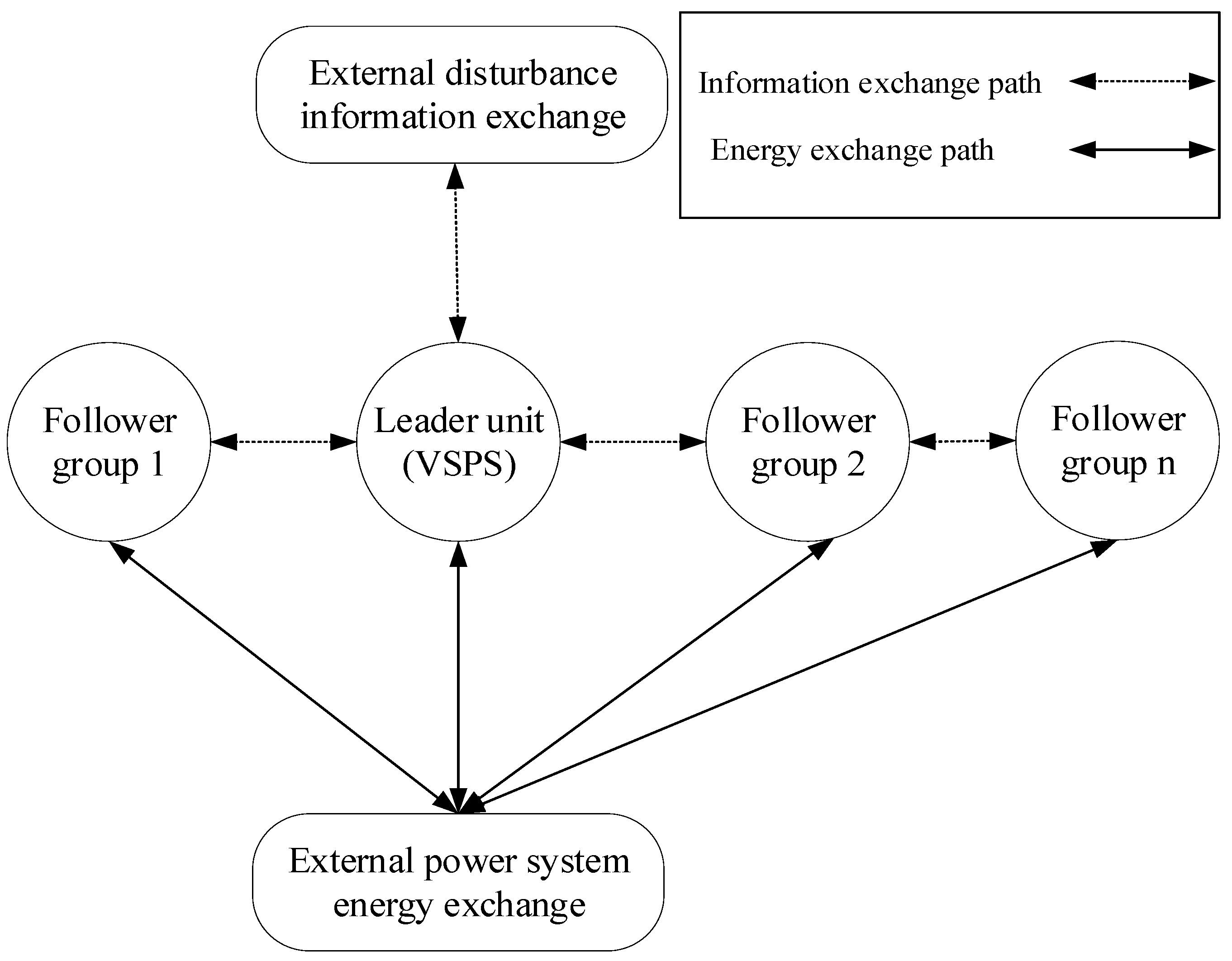
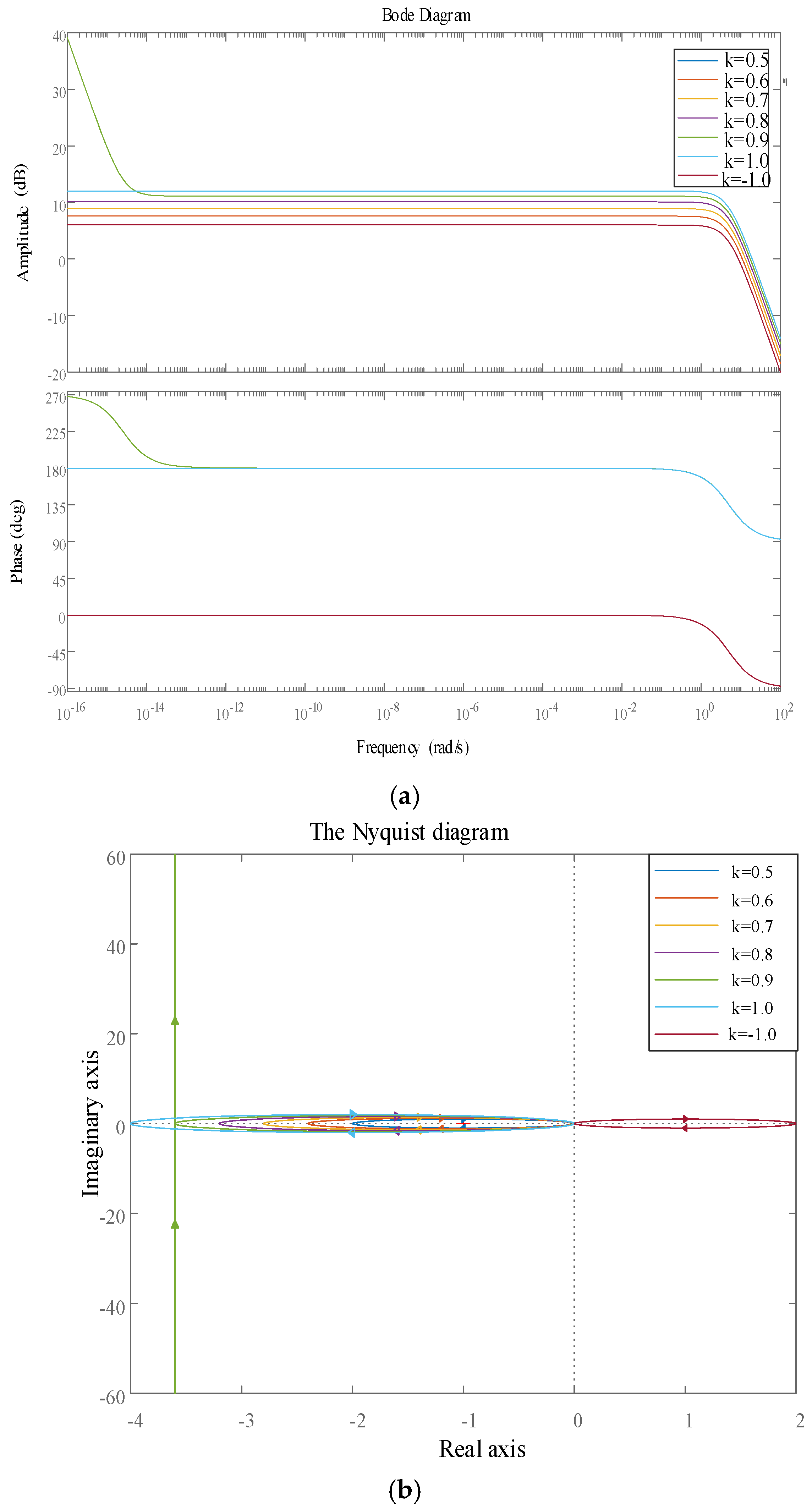
3.1. Analysis of Cooperative Optimization Strategy of Variable-Speed and Constant-Speed Pumped-Storage Units Based on Consistency Algorithm

When offshore wind turbine clusters are off-grid, the power support capacities of variable-speed pumped-storage units and fixed-speed pumped-storage units in the pumped-storage cluster are different, and the pumped-storage units have bidirectional power regulation capabilities, while the fixed-speed pumped-storage units do not have power regulation capabilities under pump conditions. Uniform power distribution cannot make full use of the power support capacity of each pumped-storage unit. This paper proposes to adopt a consistent active frequency support control strategy of the pumped-storage cluster, adopt a leadership consistency algorithm, set the VSPS as the leading unit, and give priority to power support. After the inertia support of VSPS, through the exchange of information with the neighboring fixed speed pumped-storage unit, the higher the speed of the fixed speed pumped-storage unit to release more power adjustment, the smaller the speed of the fixed speed pumped-storage unit to release fewer rotors. Rather than the traditional single pump treatment, it fully taps the kinetic energy of all pumped-storage units, and ensure operation safety.
The consistency algorithm is mainly applied to multi-agent devices [29,30,31,32]. In the consistency algorithm, if each state variable of a variable-speed-pumped-storage unit group needs to converge to an external control signal instead of a local control reference value, a control node needs to be designed to receive the external control signal, and this control node can be defined as the lead node. It is intended to set the leading node as the node state variable of the VSPS in the pumped-storage cluster, as shown in the formula. The composite consensus algorithm is a control strategy based on multi-agent systems. It allows the system to quickly restore power balance after significant disturbances through information exchange between agents. When residual power approaches consistency, the algorithm adjusts agents’ power outputs to gradually stabilize the system.
x i l · = u i l = j N i a i j x i x j + i x i Δ P .
Other constant-speed pumped-storage unit are the following units, and the state variable information is as follows:
x i f · = u i f = j N i a i j x i x j .
where xi is the state variable of a node when a major disturbance occurs in the power system VSPS i in the system; ui is the input variable of the connection node between the VSPS and the fixed-speed unit i, which is usually a function represented by the state variable of node i and adjacent node j; Δ P is the external control signal input in the consistency system. The consistency algorithm can realize that the state variables of all nodes in the variable-speed pumped-storage system converge to the external control signal Δ P . The correlation coefficient k of the consistency algorithm is the ratio of the speed ω v of the variable-speed pumped-storage unit ω D n to that of the constant-speed pumped-storage unit. The specific relationship is shown in the following equation.
ω v ω D n k .
ω v 0 + Δ ω v ω D n 0 + Δ ω D n 1 .
P V 1 = P D 1 = P D 2 = = P D n .
The initial value of the speed ω v 0 of the VSPS unit and the added value of the speed Δ ω v of the VSPS unit. ω D n 0 is the initial speed value of the constant-speed pump storage unit, and Δ ω D n is the added speed value of the constant-speed pump storage unit. P V 1 is the final power value of the VSPS, and P D 1 and P D n are the final power value of the constant-speed pumped-storage unit. The information exchange path and energy exchange path of the consistency algorithm are shown in Figure 4.
As shown in Figure 4, the external disturbance information is only exchanged with the leader unit, but the external electrical energy is exchanged with all units in the pumped-storage cluster. As VSPS (virtual synchronous power supply) contains electronic power devices, it can rapidly generate power. In contrast, fixed-speed units usually have a response delay of 0.1 to 0.3 s.

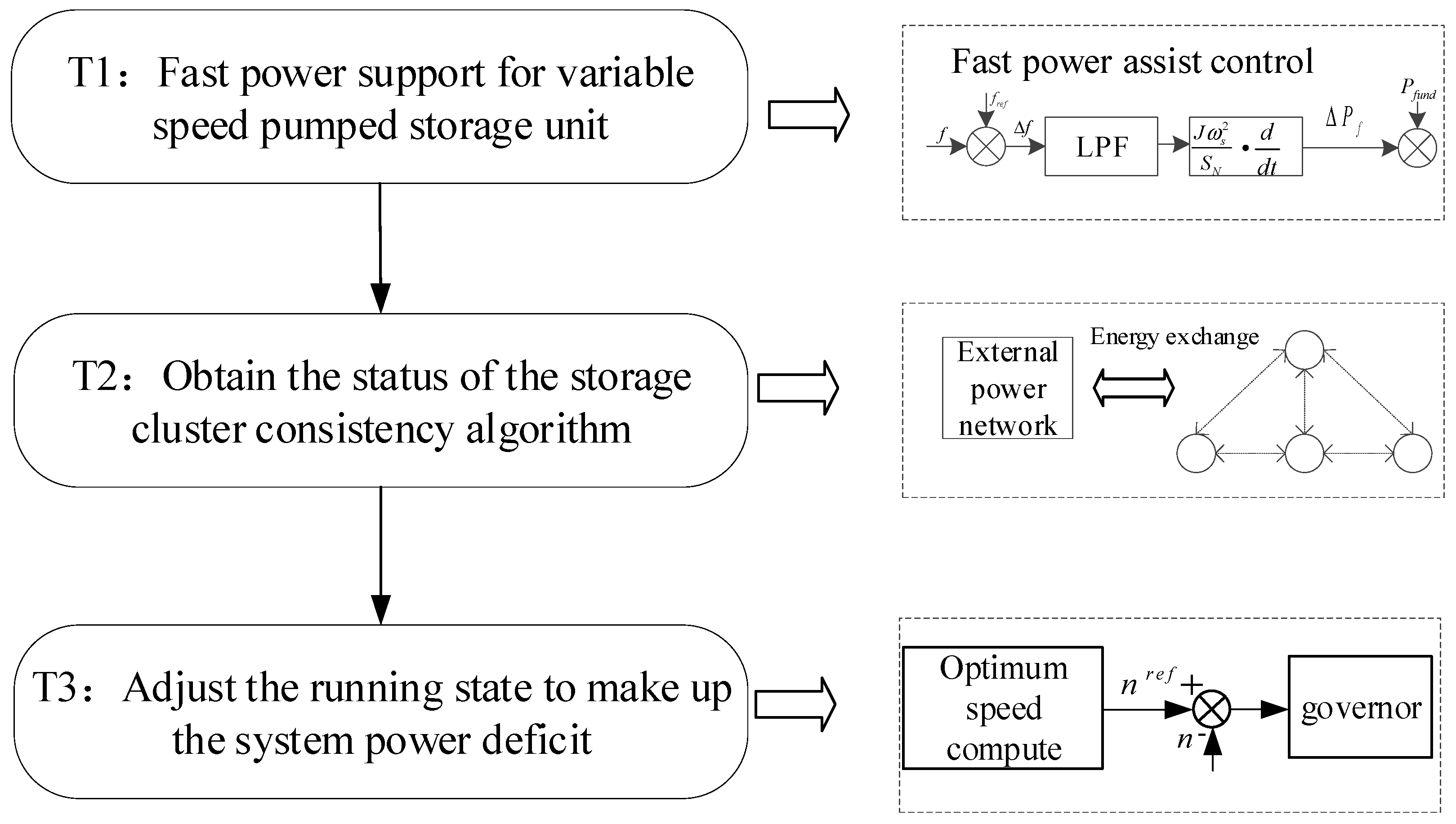
3.2. Collaborative Optimization of Variable-Speed and Fixed-Speed Pumped-Storage Units, Considering Timing

The collaborative optimization strategy of variable-speed and constant-speed pumped-storage units based on the consistency algorithm needs to consider timing coordination. In the case of off-grid offshore fans, there is a large power shortage outside. At T1, the VSPS immediately applies its fast power support capability and advanced system power shortage support to maintain the stability of the system frequency. The VSPS releases the kinetic energy of the rotor and the rotor speed drops. After the inertia support, the pumped-storage unit group status based on the consistency algorithm is obtained at T2, and then the state of the pumped-storage unit is quickly adjusted to support the external power gap with the VSPS. Figure 5 shows the cooperative scheduling process of variable-speed and fixed-speed pumped-storage unit, considering timing.
At the same time, stability analysis using fast power control and consistency algorithms should be considered. Figure 6 shows the step response and shock response diagram of the system with fast power control and consistency algorithms. Different consistency correlation coefficients are used for analysis.
Figure 6 shows the step response and shock response diagram of the system with fast power control and consistency algorithms. The smaller the consistency correlation coefficient, and if the value is positive, the better the effect of the system under step response and impulse response. Figure 7 shows the Bode diagram and Nyquist curve of the system using a fast power control and consistency algorithm. Different consistency correlation coefficients are taken for analysis.
As can be seen from the bode diagram and Nyquist curve diagram of the system with fast power control and consistency algorithms in Figure 7, the algorithm proposed in this paper has good stability at different frequencies and phases, and the consistency correlation coefficient cannot be negative, otherwise the system is unstable.

4. Analysis of Numerical Examples

In this paper, MATLAB/Simulink is used to simulate power system scenarios. The simulation step size is set to 2 × 10⁻⁵ s. For power systems with power electronic devices and other complex components, which have high switching frequencies and fast updated control signals, this step size ensures simulation accuracy and completes tasks in a reasonable time, achieving a balance between precision and efficiency.
The new energy disturbance source (1500 MW) is off-grid, the new energy disturbance source simultaneous rate is considered as 80% (1200 MW). Here, 80% refers to the simultaneous rate of offshore wind power generation of the offshore wind power cluster, not the wind power permeability rate, and a 300 MW variable-speed pumping and storage unit and two 300 MW constant-speed pumping and storage units are equipped. Figure 8 shows the joint operation block diagram of the new energy disturbance source cluster sending system and pumped-storage cluster.

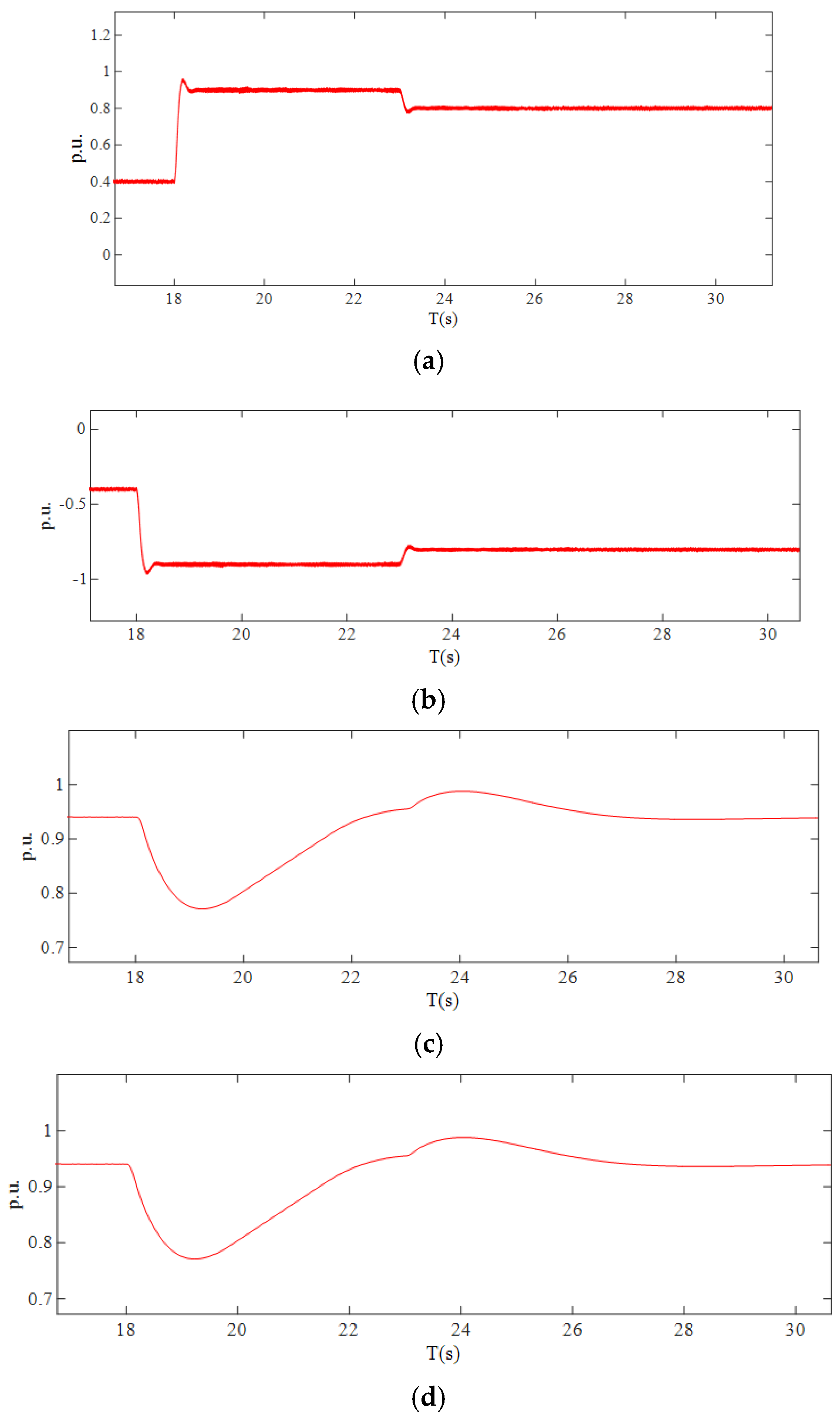
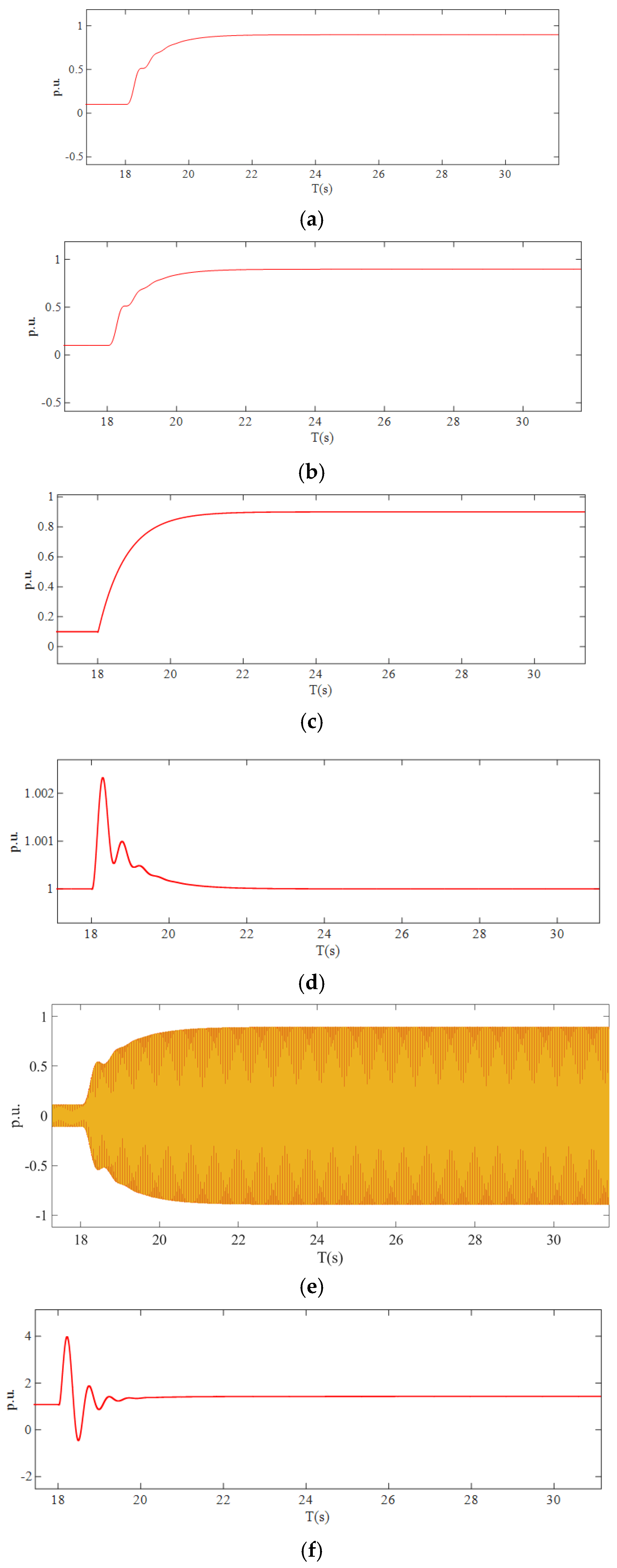
4.1. Coordinated Control of Pumping and Storage Unit Cluster

The load active power requirement is set to 1200 MW in the initial steady state. The new energy base of the new energy disturbance source cluster is P = 1200 MW, Q = 0 pu; the VSPS is 120 MW in power generation. Two constant-speed pumped-storage units are in the state of power generation P = 30 MW. The generation load of the new energy disturbance source and the active power demand of the grid side load remain unchanged, and the new energy disturbance source cluster breaks down suddenly. At this time, the power generation load of each region changes from the final state to the following: the active power demand of grid side load remains unchanged at 1200 MW; the generation power of the new energy base with half power loss becomes P = 0.5 pu (600 MW), Q = 0 pu; the VSPS quickly raises power from 0.5 pu to 0.9 pu, while the constant-speed pumped-storage unit quickly raises power from 0.1 pu to 0.8 pu following the consistency algorithm. At the same time, the VSPS is synchronously adjusted to 0.8 pu. Table 1 shows the joint simulation parameters of the new energy disturbance source and pumped-storage clusters.
The simulation analysis is carried out under the simulated working conditions. Figure 9 shows the performance variation diagram of VSPS in the regulation process, including a (a) active power output variation diagram, (b) electromagnetic torque variation diagram, (c) mechanical torque variation diagram, (d) unit speed variation diagram, (e) stator current variation diagram, and (f) rotor current variation diagram.
As shown in Figure 9a, when t = 18 s, the fast power control strategy adopted in this paper quickly reaches the rated value within 0.3 s in response to changes in active power, from 0.5 pu to 0.9 pu, and drops to 0.8 pu in 5 s when combined with the consistency algorithm of a pumped-storage cluster. In this process, the converter quickly adjusts the rotor voltage according to the change in system frequency and makes the power respond quickly when the stator active signal changes, as shown in Figure 9b, and the electromagnetic torque decreases rapidly. As shown in Figure 9c,d, the optimal speed signal is transmitted to the hydraulic turbine to adjust the motor speed. The speed is first decreased and then increased back to the original operating point. The mechanical torque drops synchronously. The electromagnetic torque and mechanical torque vary with the active reference value and are guaranteed to be in balance at constant speed. When the active power demand increases, the rotor will release part of the rotor kinetic energy to provide active power support. As shown in Figure 9f, the rotor current of the VSPS rapidly increases and the system changes accordingly. The generator can realize active power and reactive power decoupling control, and the stator current and electromagnetic torque of the motor can quickly follow the response change, as shown in Figure 9e, while the output mechanical torque of the hydraulic turbine changes slowly. The mechanical torque is controlled by the opening of the hydraulic turbine guide vane, and the working response speed of the mechanical guide vane is smaller than the electrical response speed of the excitation control. Therefore, the response speed of mechanical torque is much slower than that of electromagnetic torque.
At the same time, the following regulation of the constant-speed pumped-storage unit with consistency algorithm is considered. Figure 10 shows the performance variation diagram of the fixed-speed pumped-storage unit in the pumped-storage cluster during the adjustment process of working condition 1, including a (a) active power output variation diagram, (b) electromagnetic torque variation diagram, (c) mechanical torque variation diagram, (d) unit speed variation diagram, (e) rotor current variation diagram, and (f) excitation voltage variation diagram.
As can be seen from Figure 10a,b, when t = 18 s, the electromagnetic torque increases, and the active power increases rapidly when the stator active signal changes according to the speed given by the consistency algorithm. The reference value is reached through 4.s, increasing from 0.1 pu to 0.9 pu. It can be seen from Figure 10c,d that the hydraulic turbine increases the input mechanical torque of the synchronous motor by adjusting the opening of the guide vane and the speed change, and the output active power of the synchronous motor gradually increases, as shown in Figure 10e,f. As the output active power increases, the excitation voltage increases, and the rotor current increases. Because the initial value and final value of the two fixed-speed units in the simulation setting are the same, the parameters are the same, so the characteristics of all working conditions are the same.

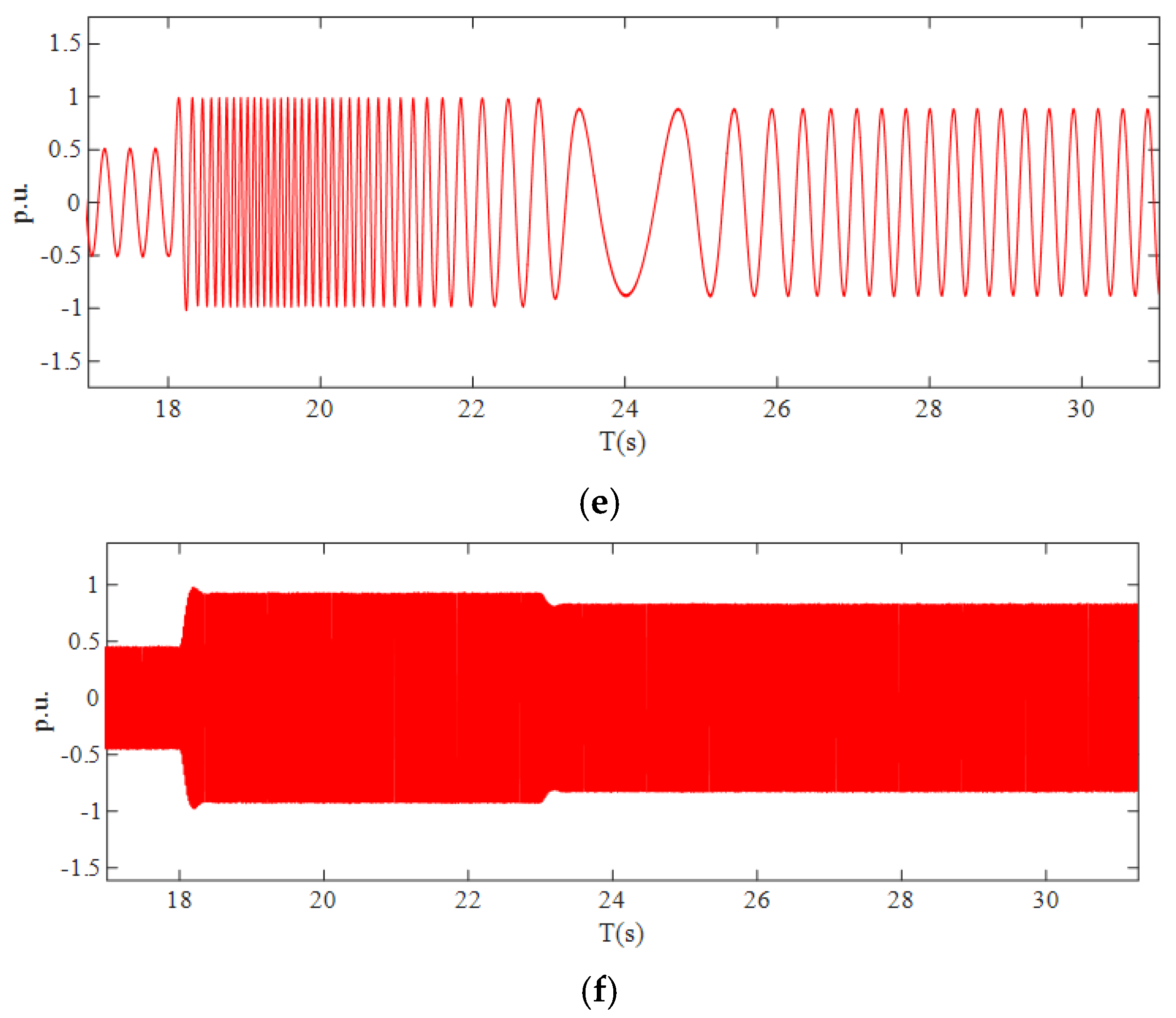
4.2. Frequency Change of the Joint System

According to the current power supply production plan, the total installed capacity of a new energy disturbance source in a certain region has reached 1500 MW. After the new energy disturbance source booster project is put into operation, each phase of the new energy disturbance source is connected to the main network through 500 kV lines. In the large wind power mode, if the fault of the outgoing line occurs, more than one million active power gaps will be generated in the grid, and the frequency drop problem will occur. In the small-load mode of the power grid, the new energy disturbance source simultaneous rate is considered as 80% (1200 MW). Here, 80% refers to the simultaneous rate of offshore wind power generation of the offshore wind power cluster, not the wind power permeability rate. If there is a fault in the outgoing line, the system frequency changes in different ways, as shown in Figure 11. Figure 11 shows the system frequency changes of the three processing methods when the new energy disturbance source is off-grid, and the wind power penetration rate is 45%. After the new energy disturbance source is taken off the grid by 50%, operating condition 1 is only adjusted by the system without taking any measures. Condition 2 is the frequency change of the traditional cutting pump 600 MW treatment system. Condition 3 is the combined power support method of the variable-speed pumping and storage unit and constant-speed unit based on a consistency algorithm. The thermal power unit is a standard 50 MW unit. These three curves are at the moment of simulation analysis. Inertia remains unchanged in different cases, load damping is the same, and the governor response modeled is the same. The method of comparison in this article mainly compares and explains the traditional method of using the governor of thermal power units and the traditional method of cutting off pumps.
The benchmark comparison in the text mainly compares and explains the system with the traditional thermal power unit governor and the traditional pump cutting method. If the power system is 45% wind power, the system frequency is expected to drop to 49.56 Hz if no action is taken. After the correct operation of the low-frequency cutting pump (two two-wheel cutting water pumps), a total of 600 MW in the whole network, the transient frequency of the system reaches the lowest, 49.70 Hz, which will not cause other measures to operate, and the steady-state frequency can be restored to 49.92 Hz. Based on the joint power support method of variable-speed extraction and storage unit and constant-speed unit based on the consistency algorithm proposed in this paper, the system frequency is expected to drop to 49.80 Hz, and with the high power and rapid support strategy of variable-speed extraction and storage unit and the joint regulation of constant-speed pumped-storage unit, the power is quickly compensated, and the frequency is quickly stabilized at about 49.8 Hz. If this study ignores generator-to-generator communication delays, a 0.1 to 0.3 s delay in fixed-speed units would postpone the overall frequency recovery in Figure 11, with no other parameter changes. During frequency support, rotor inertia converts to frequency regulation energy. The 600 MW disturbance used here is severe. For smaller disturbances, the frequency deviation would be less than that shown in our simulation.

5. Conclusions

This study focuses on the control strategy of variable-speed pumped-storage units in response to new energy disturbances at the grid’s end. The research analyzes how these units can rapidly support system inertia and proposes a collaborative optimization strategy for pumped-storage unit clusters during new energy off-grid failures, based on a consistency algorithm. The study also investigates the system’s step and impulse responses, bode and Nyquist diagrams, and using fast power control and consistency algorithm with varying consistency correlation coefficients. Furthermore, it explores the multi-characteristic changes of variable-speed and constant-speed pumped-storage units, emphasizing their coordination in supplementing power deficiencies. Simulation results indicate that the proposed method effectively stabilizes the system during large power deficits caused by new energy disturbances after going off-grid, outperforming traditional load-reduction strategies like pump cutting in enhancing frequency support, especially in power grids with large-scale renewable energy integration.

Author Contributions

W.C.: Conceptualization; Data curation; Formal analysis; Validation; Writing—original draft; and Writing—review and editing, J.X.: Formal analysis; Funding acquisition; and Writing—review and editing. All authors have read and agreed to the published version of the manuscript.

Funding

This work was supported in part by the National Natural Science Foundation of China (51777130).

Data Availability Statement

The data that support the findings of this study are available from the corresponding author upon reasonable request.

Acknowledgments

This article thanks the editorial department of the publisher and the School of Electrical Engineering at Shenyang University of Technology for their strong support.

Conflicts of Interest

The authors declare no conflict of interest.

References

  1. Ma, L.; Kong, X.; Liu, X.; Abdelbaky, M.A.; Besheer, A.H.; Wang, M.; Lee, K.Y. Offshore wind power generation system control using robust economic MPC scheme. Ocean Eng. 2023, 283, 115178. [Google Scholar] [CrossRef]
  2. Deng, J.; Cheng, F.; Yao, L.; Xu, J.; Mao, B.; Li, X.; Chen, R. A review of system topologies, key operation, and control technologies for offshore wind power transmission based on HVDC. IET Gener. Transm. Distrib. 2023, 17, 3345–3363. [Google Scholar] [CrossRef]
  3. Wang, G.; Dong, Y.; Xu, T.; He, J.; He, J.; Zhang, Y. Analysis and implications of the Brazil “8.15” black—Out accident. Proc. CSEE 2023, 43, 9461–9470. [Google Scholar] [CrossRef]
  4. Appendices to the Technical Report on the Events of 9 August 2019. Available online: https://www.neso.energy/document/152346/download (accessed on 1 March 2025).
  5. Xu, J.; Wang, X.; Zhu, L.; Shen, Y.; Guo, W.; Hu, X.; Ma, Y.; Huang, R. Stochastic optimal allocation of grid-side independent energy storage considering energy storage participating in the multi-market trading operation. AIP Adv. 2024, 14, 105223. [Google Scholar] [CrossRef]
  6. Karthik, D.; Raghu, S.; Raj, C.T. Effective Utilization of Parallel-Connected Megawatt Three-Level Back-to-Back Power Converters in Variable Speed Pumped Storage Units. IEEE Trans. Ind. Appl. 2019, 55, 6414–6426. [Google Scholar]
  7. Gao, C.; Yu, X.; Nan, H.; Guo, P.; Fan, G.; Meng, Z.; Ge, Y.; Cai, Q. Rotating speed pulling-back control and adaptive strategy of doubly-fed variable speed pumped storage unit. Renew. Energy 2024, 232, 121044. [Google Scholar] [CrossRef]
  8. Lu, Q.; Qiao, J.; Yin, X.; Yin, X.; Liu, Z.; Wang, Y.; Wang, K. A rotor open-phase imbalance protection for variable speed pumped storage unit based on rotation transformation fault component ratio. Int. J. Electr. Power Energy Syst. 2024, 160, 110105. [Google Scholar] [CrossRef]
  9. Liu, Y.; Yang, W.; Yang, J.; Huang, Y.; Zhao, Z. Quantifying power regulation characteristics in pump mode of variable-speed pumped storage unit with DFIM. Energy Sci. Eng. 2024, 12, 2837–2851. [Google Scholar] [CrossRef]
  10. Jukić, D.-K.; Kugi, A.; Kemmetmüller, W. Optimal operation of pumped storage power plants with fixed- and variable-speed generators in multiple electricity markets considering overload operation. J. Energy Storage 2024, 88, 111601. [Google Scholar] [CrossRef]
  11. Wang, H.; Li, C.; Tan, X.; Lu, X.; Zhu, Z.; Xu, R.; Liu, X.; Wang, Z. Multi-timescale analysis and quantification of dynamic regulation characteristics of DFIM-based variable-speed pumped storage units in alleviating wind power fluctuations. J. Energy Storage 2024, 88, 111482. [Google Scholar] [CrossRef]
  12. Gao, C.; Yu, X.; Nan, H.; Guo, P.; Meng, Z.; Ge, Y. The impact of hump characteristics on variable speed pumped storage units under pump mode and improvement measures. J. Energy Storage 2024, 87, 111416. [Google Scholar] [CrossRef]
  13. Tan, X.; Li, C.; Liu, D.; Wang, H.; Lu, X.; Zhu, Z.; Xu, R. Stability analysis and singular perturbation model reduction of DFIG-based variable-speed pumped storage unit adopting the fast speed control strategy. J. Energy Storage 2024, 87, 111340. [Google Scholar] [CrossRef]
  14. Malathy, N.; Sukhi, Y. Improved start-up strategy for a doubly fed induction machine fed large rated variable speed pumped storage unit in pumping mode operation. Electr. Eng. 2023, 106, 615–629. [Google Scholar] [CrossRef]
  15. Cao, R.; Guo, W.; Qu, F. Hydraulic disturbance characteristics and power control of pumped storage power plant with fixed and variable speed units under generating mode. J. Energy Storage 2023, 72, 108298. [Google Scholar] [CrossRef]
  16. Domagoj-Krešimir, J.; Andreas, K. Optimal dynamic operation of pumped storage power plants with variable and fixed speed generators. Control Eng. Pract. 2023, 138, 105601. [Google Scholar]
  17. Narayanasamy, M.; Sukhi, Y. Rotor short-circuited start-up strategy for a doubly fed induction machine-fed large-rated variable-speed pumped storage unit operating in pumping mode. J. Power Electron. 2023, 23, 1733–1744. [Google Scholar] [CrossRef]
  18. Sun, S.; Wang, X.; Lei, Y.; Lu, Y.; Song, P.; Zhang, J.; Liang, S.; Wang, B. Equilibrium analysis of doubly fed-based variable-speed pumped storage unit under remote grid fault. Energy Rep. 2023, 9, 172–177. [Google Scholar] [CrossRef]
  19. Tan, X.; Li, C.; Liu, D.; Wang, H.; Xu, R.; Lu, X.; Zhu, Z. Multi-time scale model reduction strategy of variable-speed pumped storage unit grid-connected system for small-signal oscillation stability analysis. Renew. Energy 2023, 211, 985–1009. [Google Scholar] [CrossRef]
  20. Huang, Y.; Yang, W.; Zhao, Z.; Han, W.; Li, Y.; Yang, J. Dynamic modeling and favorable speed command of variable-speed pumped-storage unit during power regulation. Renew. Energy 2023, 206, 769–783. [Google Scholar] [CrossRef]
  21. Zhao, C.; Wang, L.; Ma, Y.; Xiang, P.; Jiang, S.; Chen, W.; Zhang, Y.; Li, M. Transient Stability Simulation Analysis of Multi-Node Power Network with Variable Speed Pumped Storage Units. J. Electr. Eng. Technol. 2023, 18, 2811–2822. [Google Scholar] [CrossRef]
  22. Xu, Z.; Deng, C.; Yang, Q. Flexibility of variable-speed pumped-storage unit during primary frequency control and corresponding assessment method. Int. J. Electr. Power Energy Syst. 2023, 145, 108691. [Google Scholar] [CrossRef]
  23. Li, S.; Xie, H.; Yan, Y.; Wu, T.; Huang, T.; Liu, Y.; Li, C.; Liang, H.; Cao, T. Excitation control of variable speed pumped storage unit for electromechanical transient modeling. Energy Rep. 2022, 8, 818–825. [Google Scholar] [CrossRef]
  24. Yan, Y.; Wu, T.; Li, S.; Xie, H.; Li, Y.; Liu, M.; Zhao, Y.; Liang, H.; Zhang, G.; Xin, H. Optimal operation strategies of pumped storage hydropower plant considering the integrated AC grids and new energy utilization. Energy Rep. 2022, 8, 545–554. [Google Scholar] [CrossRef]
  25. Feng, C.; Zheng, Y.; Li, C.; Mai, Z.; Wu, W.; Chen, H. The cost advantage of adjustable-speed pumped storage unit for daily operation in distributed hybrid system. Renew. Energy 2021, 176, 1–10. [Google Scholar] [CrossRef]
  26. Feng, C.; Li, C.; Chang, L.; Ding, T.; Mai, Z. Advantage analysis of variable-speed pumped storage units in renewable energy power grid: Mechanism of avoiding S-shaped region. Int. J. Electr. Power Energy Syst. 2020, 120, 105976. [Google Scholar] [CrossRef]
  27. Liu, X.-K.; Wang, Y.-W.; Liu, Z.-W.; Huang, Y. Synergistic Operation Framework for the Energy Hub Merging Stochastic Distributionally Robust Chance-Constrained Optimization and Stackelberg Game. IEEE Trans. Energy Convers. 2024, 39, 10666779. [Google Scholar]
  28. Zhang, H.; Li, H.; Wang, Z.; Chen, G.; Wen, C. Distributed Hybrid-Triggered Observer-Based Secondary Control of Multi-Bus DC Microgrids Over Directed Networks. IEEE Trans. Ind. Inform. 2025, 20, 10945–10954. [Google Scholar]
  29. Lee, S.J.; Choi, J.Y.; Lee, H.J.; Won, D.J. Distributed coordination control strategy for a multi-microgrid based on a consensus algorithm. Energies 2017, 10, 1107. [Google Scholar] [CrossRef]
  30. Yang, J.; Hou, J.; Liu, Y.; Zhang, H. Distributed cooperative control method and application in power system. Trans. China Electrotech. Soc. 2021, 36, 4035–4049. [Google Scholar]
  31. Xu, B.; Yu, X.; Yang, Y. Distributed wind-storage coordinate frequency control strategy based on a multi-agent system. Power Syst. Prot. Control 2022, 50, 13–24. [Google Scholar]
  32. Tang, M.; Qu, X.; Yao, R.; Zhang, Y.; Chen, W.; Jia, K. Multi-photovoltaic coordinated control strategy in DC distribution network based on discrete consensus algorithm. Autom. Electr. Power Syst. 2020, 44, 89–95. [Google Scholar]
Figure 1. Topology of doubly-fed VSPS.
Energies 18 02441 g001
Figure 2. Control block diagram of machine side converter with fast power control.
Energies 18 02441 g002
Figure 3. Control block diagram of the governor of constant-speed pumped-storage unit.
Energies 18 02441 g003
Figure 4. Information exchange path and energy exchange path diagram of the consistency algorithm.
Energies 18 02441 g004
Figure 5. Collaborative scheduling process of variable-speed and fixed-speed pumped-storage unit, considering timing.
Energies 18 02441 g005
Figure 6. Step response and impulse response diagram of the system with fast power control and consistency algorithm. (a) Step response diagram of the system with different consistency correlation coefficients. (b) System impulse response diagram with different consistency correlations.
Energies 18 02441 g006
Figure 7. Bode diagram and Nyquist curve of the system with fast power control and consistency algorithm. (a) Bode diagram of the system with different consistency correlation coefficients. (b) System Nyquist curve with different consistency correlation coefficients.
Energies 18 02441 g007
Figure 8. Joint operation block diagram of new energy disturbance source cluster delivery system and pumped-storage cluster.
Energies 18 02441 g008
Figure 9. Performance changes of variable-speed pumped-storage unit during the regulation of power generation conditions. (a) Active power output of VSPS. (b) Electromagnetic torque variation diagram of VSPS. (c) Mechanical torque variation diagram of VSPS. (d) Variation diagram of the unit speed of VSPS. (e) Stator current variation diagram of VSPS. (f) Rotor current variation diagram of VSPS.
Energies 18 02441 g009aEnergies 18 02441 g009b
Figure 10. Performance changes of variable-speed pumped-storage unit during the regulation of power generation conditions. (a) Variation diagram of the active power output of constant-speed pumped-storage unit. (b) Electromagnetic torque variation diagram of constant-speed pumped-storage unit. (c) Mechanical torque variation diagram of constant-speed pumped-storage unit. (d) Constant-speed pumped-storage unit speed variation diagram. (e) Rotor current variation diagram of constant-speed pumped-storage unit. (f) Excitation voltage variation diagram of constant-speed pumped-storage unit.
Energies 18 02441 g010
Figure 11. System frequency variation in the case of 45% wind power penetration after a new energy disturbance source is offline.
Energies 18 02441 g011
Table 1. Joint simulation parameters of new energy disturbance source and pumped-storage cluster.
Electric Power ParametersNumerical Electric Power ParametersNumerical
New energy disturbance source1500 MWSimultaneous rate of offshore wind cluster80%
Variable-speed pumping and storage unit power300 MWLoad active power Initial demand power1200 MW
Constant-speed pumping and storage unit 1 power300 MWLoad active power Initial demand power for off-grid fans1200 MW
Constant-speed pumping and storage unit 2 power300 MWThe new energy disturbance source cluster can generate power after failure600 MW
Initial state of VSPS120 MWMultiple power after a variable-speed pumping cluster failure600 MW
Disclaimer/Publisher’s Note: The statements, opinions and data contained in all publications are solely those of the individual author(s) and contributor(s) and not of MDPI and/or the editor(s). MDPI and/or the editor(s) disclaim responsibility for any injury to people or property resulting from any ideas, methods, instructions or products referred to in the content.

