Abstract
The power conversion system of a small micro-reactor has strict requirements on the compactness of the rotating mechanical support. Although the active magnetic bearing is an ideal choice, the thermally induced vibration caused by it may destroy the stability of the system. As such, this study proposes a multi-physics coupling simulation framework, which integrates electromagnetic, thermal, and mechanical multi-physics coupling mechanisms and quantifies the stability of the system under thermal-induced vibration in the frequency domain. Firstly, the equivalent magnetic circuit and electromagnetic finite element modeling and calculation of the compressor rotor are carried out. In the case of the maximum AC current of 10 A, the equivalent stiffness of the magnetic pole is 4.21 × 10⁸ N/m and 2.1 × 10⁸ N/m, and the eddy current loss of the rotor is 4.17496 W. Based on the eddy current loss, a magneto-thermal coupling model is established to reveal the temperature gradient distribution and the thermal sensitivity coefficient of the journal is 0.006. Subsequently, the thermal stress and equivalent stiffness are coupled to the rotor dynamics equation, and the maximum amplitude of the rotor is obtained at a value of 0.001 mm. Finally, the critical stability threshold of the system is determined by a Nyquist diagram, and the results show that the system is stable as a whole. In this paper, the quantitative analysis of the cross-scale coupling mechanism of electromagnetic, thermal, and mechanical multi-physical fields is realized, which provides a systematic analysis method for the thermally induced vibration of magnetically suspended rotors and has important engineering significance for high power density rotating mechanical systems in small micro-reactors.
1. Introduction
Small micro-reactors are a hot reactor type in the nuclear industry [1,2]. The micro-reactor requires a power conversion system with high energy density, and that is lightweight [3]. The core equipment of the power conversion system is rotating machinery. In order to achieve the compactness of the system by increasing the speed of the rotating machinery, it is necessary to design a high-speed compact bearing [4]. The non-contact and non-lubrication characteristics of the magnetic bearing show a significant compact advantage in the structure, which can effectively improve the performance of the rotor under high-speed operation conditions and is superior to other bearings [5].
However, the active magnetic bearing (AMB) will produce eddy current loss that causes rotor vibration, which is manifested as spiral vibration [6] and is called thermally induced vibration. In 2013, Naohiko Takahashi [7] pointed out the principle of thermally induced vibration of the rotor caused by magnetic bearings: unbalanced vibration makes the magnetic flux density concentrated in a certain part of the rotor, and the iron loss is large in the high magnetic flux density area, which leads to the uneven distribution of iron loss and thermal bending. Thermal bending will produce a new unbalanced force, which will lead to the further concentration of the magnetic flux of the rotor. Such a vicious cycle eventually leads to increased vibration [8,9].
It can be seen from this principle that the thermally induced vibration caused by the active magnetic bearing is essential because the rotor is subjected to the dual effects of a mechanical unbalanced force and thermal gradient force at the same time. It is difficult to accurately predict the system’s behavior by single physical field analysis and calculation. Therefore, multi-physics coupling analysis, including electromagnetic, thermal, structural, and rotor dynamics, is indispensable [10].
For the multi-physical coupling simulation analysis of electromagnetic bearings, most scholars have calculated the loss of electromagnetic thermal coupling and obtained the temperature distribution field [8,11,12] without considering the effect on rotor dynamics.
In multi-physics analysis, where the research object is not AMB, the necessity of rotor dynamics included in multi-physics analysis has been considered. Liu, J. and P. Zhang [13] integrated heat and rotor dynamics to analyze the significant influence of thermal expansion of angular contact bearings on bearing stiffness and system dynamic characteristics. Y. Li, Y. Zhang, Y. Zhao, and X. Shi [14] solved the rotor supported by angular contact ball bearings using a thermal–mechanical two-way coupling iteration. M. Sun, Y. Xu, and W. Zhang [15] analyzed the coupling of the electromagnetic, thermal, mechanical, and fluid multi-physical fields of the motor. K. Wang, X. Ma, Q. Liu, S. H. Chen, and X. Q. Liu [16] carried out stress, modal, electromagnetic, and thermal fluid coupling analysis from the perspective of motor design to provide a reference for global design. S. J. Guo and C. Q. Bai [17] established a two-degrees-of-freedom magnetic, solid, and thermal coupling model to analyze and calculate the multi-field coupling vibration of high-speed motors. J. J. Scheidler, T. F. Tallerico, E. J. Stalcup, and K. P. Duffy [18] modified the thermal model, optimized the structure, and designed the rotor dynamics to meet the temperature, structure, and magnetic field requirements of high-temperature superconducting coils.
The above multi-physical coupling analysis related to thermally induced vibration has made a lot of progress, but there is a lack of multi-physical research on the phenomenon of thermally induced vibrations caused by electromagnetic bearings, and the existing multi-physical analysis of electromagnetic bearings fails to deeply describe the whole process of the dynamic coupling interaction mechanism under thermally induced vibration.
In view of the above problems, this paper proposes a multi-physical coupling analysis and calculation of the whole process, including electromagnetic, thermal, structural, and rotor dynamics calculations. Firstly, the finite element coupling calculation of electromagnetic, magnetothermal, and thermal structures is carried out. In the thermal structure calculation, the thermal gradient of the rotor is calculated with time. The spatial distribution changes, and then the equivalent stiffness obtained by the electromagnetic analysis and the thermal stress generated by the thermal gradient are comprehensively considered in the rotor dynamics for interactive calculation and coupling. Finally, the calculated rotor thermal effect coefficient is substituted into the system for stability analysis. In this paper, the multi-physical coupling calculation of the thermally induced vibration caused by magnetic bearing is carried out, and the simulation analysis of the whole process of electromagnetic–thermal–structure–rotor dynamics is included. A multi-physical coupling calculation and analysis framework of the thermally induced vibration caused by the magnetic bearing is also proposed.
2. System Structure and Multi-Physics Coupling Analysis Framework
2.1. System Structure
Figure 1 shows the radial and axial magnetic bearings of the compressor rotor and the supporting rotor. The rotor is an integrated stepped shaft structure. The radial magnetic bearing adopts an active magnetic bearing with a 12-pole E-shaped magnet structure, and its structure and current parameters are shown in Table 1.
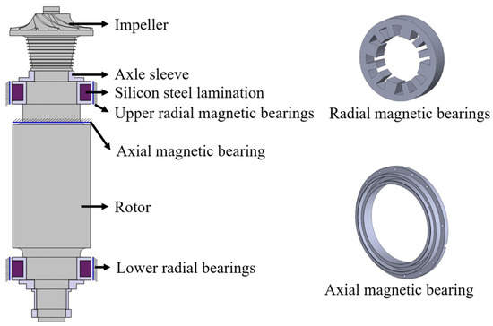
Figure 1.
Structure diagram of the rotor-magnetic bearing system.

Table 1.
Structure and current parameters of radial magnetic bearing.
2.2. Multi-Physics Coupled Analysis Architecture
Figure 2 illustrates the multi-physics analysis framework of this paper. The framework includes finite element electromagnetic calculation, magneto-thermal coupling, thermal structure coupling, rotor dynamics calculation, and stability analysis in the frequency domain. The current is the basic input of the system. Firstly, the electromagnetic coupling analysis of the magnetic bearing rotor system is carried out. The control current is an alternating current, and the rotor surface produces an eddy current loss. Secondly, the magneto-thermal analysis is carried out, and the eddy current loss is used as the heat source input to obtain the temperature distribution of the rotor journal. Thirdly, temperature is used as the input of the thermal structure coupling calculation to determine the spatial distribution of the thermal stress on the radial surface of the rotor. Then, the influence of spatial non-uniform thermal stress and the equivalent stiffness of electromagnetic bearing is applied to the rotor shaft, and the rotor dynamics calculation is carried out to analyze the vibration characteristics of the system. Finally, the previously calculated thermal coefficient H and equivalent stiffness are substituted into the dynamic equation of the system for frequency domain stability analysis.
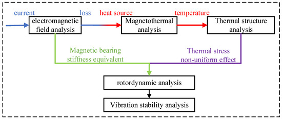
Figure 2.
Multi-physical analysis architecture.
3. Electromagnetic Coupling
Electromagnetic analysis is divided into two path modeling calculations. The equivalent magnetic circuit method is used to solve the mathematical relationship between the electromagnetic force and the air gap, and the equivalent stiffness is derived to prepare for the rotor dynamics and frequency domain stability analysis. The other path is calculated using the electromagnetic finite element method to obtain the loss, which is used for the subsequent magneto-thermal coupling calculation.
3.1. Equivalent Magnetic Circuit and Stiffness Equivalent
As shown in Figure 3a, an equivalent magnetic circuit is established. Analogous to the circuit, magnetic flux, magnetoresistance, and magnetomotive force obey Ohm’s law. The E-type bearing is 1/4 symmetrical and can be divided into four quadrants, so only one quadrant is taken for the analysis and calculation, as shown in Figure 3b.
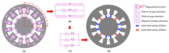
Figure 3.
(a) Magnetic equivalent circuit modeling; (b) single quadrant analysis; (c) simplified magnetic circuit model; and (d) equivalent stiffness model.
The calculation formula of magnetoresistance is as follows:
where l is the length of the equivalent path, S is the corresponding area, and is the permeability.
According to Equation (1), the relative permeability of the magnetic bearing core is about 5000, which is much higher than that of air (where relative permeability is one). Therefore, it can be considered that the magnetomotive force is mainly concentrated in the air gap, ignoring the influence of the iron core. The simplified magnetic circuit model is shown in Figure 3c, and the following equations are obtained by mathematical modeling:
where is the magnetic flux, is the equivalent reluctance of the wide magnetic pole, is the number of turns of the wide magnetic pole coil, I is the incoming current, is the equivalent reluctance of the narrow magnetic pole, is the number of turns of the narrow magnetic pole coil, and B is the magnetic induction intensity of the air gap.
The expressions of available magnetic flux for simultaneous Equations (1) and (2) are as follows:
where is the vacuum permeability, is the cross-sectional area of the narrow pole, is the cross-sectional area of the wide pole, and x is the air gap length.
The air gap energy storage corresponding to each magnetic pole conforms to the following:
where H is the magnetic field intensity of the air gap, and Va is the volume of the air gap.
The following principle of virtual displacement can be used to solve the magnetic force:
The relationship between the magnetic field force and the displacement of the rotor is obtained as follows:
where FS is the electromagnetic force corresponding to the wide magnetic pole, and FN is the electromagnetic force corresponding to the narrow magnetic pole.
From Equations (7) and (8), the relationship between electromagnetic force and displacement is a non-linear relationship, and the magnetic bearing needs to use the control theory to suppress the vibration, so the linear relationship is the first choice for calculation. Therefore, the derivation at the working point is performed. Approximate linearization is performed to obtain the equivalent stiffness of the magnetic bearing:
where kxS is the equivalent stiffness corresponding to the electromagnetic force of the wide magnetic pole, and kxN is the equivalent stiffness corresponding to the electromagnetic force of the narrow magnetic pole.
The equivalent stiffness of the magnetic bearing is calculated when the maximum current is 10A. By substituting the relevant data of the magnetic bearing in Table 1 into Equations (9) and (10), the equivalent stiffness of the wide magnetic pole of the magnetic bearing is N/m, and the equivalent stiffness of the narrow magnetic pole is N/m.
3.2. Electromagnetic Finite Element Calculation of Electromagnetic Bearings
The electromagnetic calculation of the model is carried out using Ansys Mechanical APDL 2023 R1, and the three-dimensional model is analyzed. The input is an alternating current with an amplitude of 10 A. In the Ansys electromagnetic calculation, the edge transient analysis method in APDL must be used for the three-dimensional model and AC input. The stator, rotor, air, and coil of the bearing are modeled as SOLID236 units. The SOLID236 element is a cuboid used to calculate the degree of freedom (AZ) of the magnetic flux, which is suitable for the edge analysis of electromagnetic problems in Ansys Mechanical APDL. The electromagnetic finite element model of the radial magnetic bearing and rotor is shown in Figure 4a.
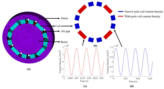
Figure 4.
(a) Electromagnetic finite element model of the system; (b) coil current density distribution; (c) wide magnetic pole current density; and (d) narrow magnetic pole current density.
Because the winding and area of the wide magnetic pole and the narrow magnetic pole are different, the corresponding current density is different, as shown in Figure 4b. The calculated current density amplitudes of the wide magnetic pole and the narrow magnetic pole are , , as shown in Figure 4c,d. The current density is used as the input of the finite element model. When the coil is fed into the alternating current, an induced eddy current will be generated on the surface of the rotor. As shown in Figure 5a, an induced eddy current is present on the rotor journal. Figure 5b shows the Joule heat distribution per unit volume on the rotor journal calculated by the electromagnetic calculation. The total eddy current loss on the rotor journal is 4.17496 W after volume addition.
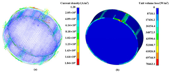
Figure 5.
(a) Journal-induced eddy current; (b) Joule heat distribution per unit volume of journal.
4. Magneto-Thermal Coupling
Finite element models such as stator, air, and coil are deleted, and the flux parallel conditions of the outermost nodes of the model are deleted. The SOLID236 unit defined in the electromagnetic calculation is replaced by the SOLID279 cuboid unit dedicated to the magneto-thermal coupling calculation. The loss generated on the rotor journal calculated by the electromagnetic coupling is used as the heat source input. The ambient temperature is set to 25 °C, and the rotor surface is subjected to convective heat transfer with the surrounding air gap capable of obtaining the temperature distribution of the rotor journal, as shown in Figure 6. Due to the eddy current loss caused by the alternating current of the magnetic pole coil, the distribution law of the journal surface temperature is that the journal surface temperature relative to the magnetic pole is higher, and the temperature gradient distribution law is reduced in other directions.
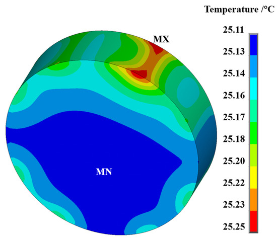
Figure 6.
Temperature distribution of rotor journal.
In order to quantitatively represent the temperature gradient distribution of the journal, the thermal sensitivity coefficient H of the rotor is defined to represent the degree of uneven temperature distribution. H is defined as a dimensionless proportional constant by considering the ratio of the difference between the maximum temperature and the minimum temperature of the journal surface to the average temperature of the journal surface. This is shown below:
where Tmax is the highest temperature of the journal, Tmin is the lowest temperature of the journal, and Tavg is the average temperature.
As shown in Figure 6, the maximum temperature at the rotor journal is 25.25 °C; the minimum temperature is 25.11 °C; and the average temperature is 25.18 °C. The thermal sensitivity coefficient of the rotor is calculated to be H = 0.006.
5. Heat Structural Coupling
The convective heat transfer conditions defined on the surface of the journal are deleted, and the SOLID279 element defined in the magneto-thermal calculation is replaced by the SOLID186 cuboid element, which can be used for the thermal coupling calculation. The full degree of freedom of the two surfaces of the journal shaft, both forward and backward, is constrained. The temperature obtained by magneto-thermal coupling is used as the input of the thermal–structural coupling finite element calculation, and the thermal deformation and equivalent stress of the rotor journal can be obtained. Figure 7a shows the thermal deformation of the journal. The maximum thermal expansion deformation of about 0.02 mm occurs in the middle of the journal, and the deformation decreases along the axial middle of the journal to both sides. Figure 7b,c are the stress contours in the X and Y directions, respectively. The X direction is only 0.074 N, and the Y direction is only 0.087 N, which also reflects the slow growth of thermally induced vibration over time.
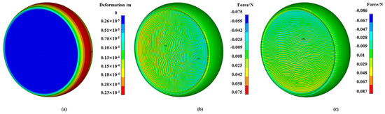
Figure 7.
(a) Thermal deformation of the journal; (b) X direction force cloud diagram; and (c) Y direction force cloud diagram.
6. Rotor Dynamic Analysis
The calculation of rotor dynamics is carried out in APDL. Firstly, the rotor is modeled, as shown in Figure 8b. The impeller and sleeve are equivalently defined as Mass21 elements. The definition of Mass21 elements can transform the non-axisymmetric part of the rotor into an equivalent axisymmetric mass to facilitate calculation. All shaft segments of the rotor are defined as a Beam188 element, which is based on the Timoshenko beam theory.
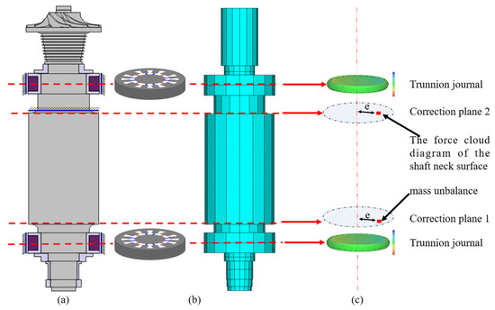
Figure 8.
(a) Rotor model; (b) rotor dynamics modeling; and (c) the effects of unbalanced force and thermal stress.
As shown in Figure 8b,c, the equivalent stiffness of the electromagnetic bearing and the thermal stress in the X and Y directions calculated by the thermal structure are substituted into the model for calculation. In addition, the effect of unbalanced force should also be considered, which can be referred to as the balance quality grade G0.4. It is known that the working speed of the rotor is 12,000 r/min, and the rotor mass is about 5000 kg. The allowable residual imbalance of the rotor is calculated as follows:
where Uper is the allowable unbalance of the rotor, G0.4 is the allowable grade, m is the mass of the rotor, and is the rotational speed.
As shown in Figure 8c, Uper is assigned to two correction planes. According to the ISO 1940 standard [19], the following allocations can be made:
where Up1 is the allowable unbalance of correction plane 1, and Up2 is the allowable unbalance of correction plane 1.
Assuming that the mass imbalance is located at 50 mm from the axis, the mass imbalance can be calculated as 0.016 kg, and the unbalanced phase is 90 degrees.
The harmonic response of the rotor’s unbalanced response is analyzed by the full method. The excitation frequency of the electromagnetic force is synchronized with the rotation frequency of the rotor. The frequency range of harmonic analysis is defined as 0~200 Hz. After opening the Coriolis effect, the solution can be obtained. When the excitation frequency changes from 0 to 200 Hz, the amplitude changes at the two shaft necks of the rotor, as shown in Figure 9. It can be seen that the amplitude is small at 200 Hz.
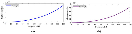
Figure 9.
(a) Rotor amplitude of lower radial bearing; (b) rotor amplitude of upper radial bearing.
7. System Stability Analysis
As shown in Figure 10, the force diagram of the journal of the rotor supported by the magnetic bearing is shown; that is, the single-degree-of-freedom rotor is subjected to an unbalanced force, electromagnetic force, or thermal stress during rotation.
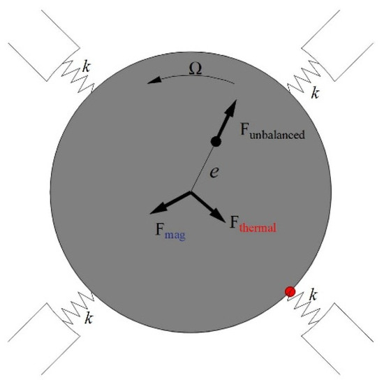
Figure 10.
Rotor journal force diagram.
At this time, the motion equation of the rotor is as follows:
where z represents the amplitude, Fmag represents the electromagnetic force, Fthermal represents the unbalanced force caused by heat, and Fumbalanced represents the unbalanced force.
The relationship between Fmag and displacement was obtained in electromagnetic calculation and analysis. The unbalanced force Fthermal caused by the thermal bow is proportional to the magnetic force Fmag. Here, it is assumed that the first-order time-delay system represents the following:
where T is the time constant, and H is the thermal sensitivity of the rotor.
The expressions of Fmag and Fthermal are substituted into Equation (14); the unbalanced force is taken as the input; and the displacement of the rotor is taken as the output. The Laplace transform is used to transform this into the frequency domain for analysis, and the block diagram of the system motion is obtained, as shown in Figure 11.
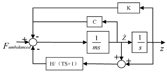
Figure 11.
Block diagram of the system.
The calculated parameters are substituted into the equation, and then the Nyquist diagram is drawn up to judge the stability of the system, as shown in Figure 12.
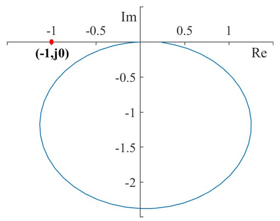
Figure 12.
The Nyquist diagram of the system.
It can be seen from Figure 12 that the Nyquist curve does not surround the (−1, j0) points, and the open-loop transfer function of the system indicates that the number of closed-loop poles of the system is 0, so the system is stable.
8. Conclusions
In this paper, a multi-physics coupling dynamics simulation framework is proposed to analyze the thermally induced vibration of the magnetic suspension rotor in nuclear reactors. The influence of electromagnetic, thermal, and mechanical coupling on rotor dynamics is studied. The analysis includes electromagnetic coupling to calculate eddy current loss, magneto-thermal coupling to obtain temperature distribution, thermal–structural coupling to determine thermal stress distribution, and rotor dynamics analysis to evaluate the vibration characteristics of the system. The stability of the system is evaluated using the Nyquist diagram. The proposed framework fills the gap in the existing literature by systematically discussing the unique multi-physical field coupling mechanism of electromagnetic bearings and its dynamic coupling interaction under thermally induced vibration. However, the current model is based on the assumption of steady-state conditions, and the numerical results have not been verified by physical experiments. In the future, parameter inversion should be carried out in combination with high-speed rotor bench experiments to further improve the adaptability of the framework with regard to actual engineering scenarios and provide more reliable theoretical support for the thermal protection design of high-power density maglev systems.
Author Contributions
Conceptualization, Y.X. and Z.L.; methodology, Y.X. and Z.L.; software, Y.X.; validation, Y.X.; formal analysis, Y.X.; writing—original draft, Y.X.; writing—review & editing, Z.L. and D.X. All authors have read and agreed to the published version of the manuscript.
Funding
This research was funded by National Key Research and Development Project of China, No. 2020YFB1901700, and the APC was funded by Tsinghua University Initiative Scientific Research Program.
Data Availability Statement
The original contributions presented in the study are included in the article, further inquiries can be directed to the corresponding author.
Conflicts of Interest
Author Dianchuan Xing was employed by Nuclear Power Institute of China (CNNC). The remaining authors declare that the research was conducted in the absence of any commercial or financial relationships that could be construed as a potential conflict of interest.
References
- Teräsvirta, A.; Syri, S.; Hiltunen, P. Small Nuclear Reactor-Nordic District Heating Case Study. Energies 2020, 13, 3782. [Google Scholar] [CrossRef]
- Alam, S.B.; Ridwan, T.; Kumar, D.; Almutairi, B.; Goodwin, C.; Parks, G.T. Small modular reactor core design for civil marine propulsion using micro-heterogeneous duplex fuel. Part II: Whole-core analysis. Nucl. Eng. Des. 2019, 346, 176–191. [Google Scholar] [CrossRef]
- Liu, Y.; Zhao, Z.W.; Wang, Y.C.; Zhao, F.; Lu, D.G.; Cao, Q. Dynamic response of a multi-point mooring cylindrical floating nuclear power platform carrying a small-scale reactor. Ocean Eng. 2023, 267, 14. [Google Scholar] [CrossRef]
- Bhowmik, P.K.; Sabharwall, P.; Johnson, J.T.; Retamales, M.E.T.; Wang, C.; Brien, J.E.; Lietwiler, C.; Wu, Q. Scaling methodologies and similarity analysis for thermal hydraulics test facility development for water-cooled small modular reactor. Nucl. Eng. Des. 2024, 424, 15. [Google Scholar] [CrossRef]
- Zheng, Y.; Mo, N.; Sun, Z.; Zhou, Y.; Shi, Z. Study on Unbalanced Magnetic Pulling Analysis and Its Control Method for Primary Helium Circulator of High-Temperature Gas-Cooled Reactor. Energies 2019, 12, 3682. [Google Scholar] [CrossRef]
- Plantegenet, T.; Arghir, M.; Hassini, M.-A.; Jolly, P. The Thermal Unbalance Effect Induced by a Journal Bearing in Rigid and Flexible Rotors: Experimental Analysis. Tribol. Trans. 2019, 63, 52–67. [Google Scholar] [CrossRef]
- Takahashi, N.; Kaneko, S. Thermal instability in a magnetically levitated doubly overhung rotor. J. Sound Vib. 2013, 332, 1188–1203. [Google Scholar] [CrossRef]
- Jin, C.; Su, H.; Dong, Y.; Zhou, J.; Xu, Y.; Yan, X. Iron loss analysis of magnetic bearing system considering magnetic-thermal coupling. Int. J. Appl. Electromagn. Mech. 2022, 70, 1–20. [Google Scholar] [CrossRef]
- Hassini, M.-A. Numerical and experimental analysis of stable, unstable, and limit cycle spiral vibrations. Mech. Syst. Signal Process. 2023, 193, 110258. [Google Scholar] [CrossRef]
- He, Q.; Wang, J.; Li, K.; Wang, X.; Xu, Z.; Zhang, Y. Thermal analysis and thermal management of high power density electric motors for aircraft electrification. Appl. Therm. Eng. 2025, 260, 125006. [Google Scholar] [CrossRef]
- Zhang, X.; Han, B.C.; Liu, X.; Chen, Y.L.; Zhai, L.X. Prediction and experiment of DC- bias iron loss in radial magnetic bearing for a small scale turbomolecular pump. Vacuum 2019, 163, 224–235. [Google Scholar] [CrossRef]
- Zhai, L.X.; Han, B.C.; Liu, X.; Zhao, J.H. Losses estimation, thermal-structure coupled simulation analysis of a magnetic-bearing reaction wheel. Int. J. Appl. Electromagn. Mech. 2019, 60, 33–53. [Google Scholar] [CrossRef]
- Liu, J.; Zhang, P. Thermo-mechanical behavior analysis of motorized spindle based on a coupled model. Adv. Mech. Eng. 2018, 10, 168781401774714. [Google Scholar] [CrossRef]
- Li, Y.; Zhang, Y.; Zhao, Y.; Shi, X. Thermal-mechanical coupling calculation method for deformation error of motorized spindle of machine tool. Eng. Fail. Anal. 2021, 128, 105597. [Google Scholar] [CrossRef]
- Sun, M.; Xu, Y.; Zhang, W. Multiphysics Analysis of Flywheel Energy Storage System Based on Cup Winding Permanent Magnet Synchronous Machine. IEEE Trans. Energy Convers. 2023, 38, 2684–2694. [Google Scholar] [CrossRef]
- Wang, K.; Ma, X.; Liu, Q.; Chen, S.H.; Liu, X.Q. Multiphysics Global Design and Experiment of the Electric Machine with a Flexible Roto Supported by Active Magnetic Bearing. IEEE-ASME Trans. Mechatron. 2019, 24, 820–831. [Google Scholar] [CrossRef]
- Guo, S.J.; Bai, C.Q. Experimental and Numerical Research Studies on Multifield Coupling Rotordynamic Behaviors of Motor. Shock. Vib. 2021, 2021, 5550804. [Google Scholar] [CrossRef]
- Scheidler, J.J.; Tallerico, T.F.; Stalcup, E.J.; Duffy, K.P. Thermal, Structural, and Rotordynamics Refinements to the Superconducting Rotor of a 1.4 MW Partially Superconducting Machine for Electrified Aircraft. IEEE Trans. Appl. Supercond. 2025, 35, 5203005. [Google Scholar] [CrossRef]
- ISO 1940-1; Mechanical Vibration—Balance Quality Requirements for Rotors in a Constant (Rigid) State—Part 1: Specification and Verification of Balance Tolerances. The ISO Council: Geneve, Switzerland, 2003.
Disclaimer/Publisher’s Note: The statements, opinions and data contained in all publications are solely those of the individual author(s) and contributor(s) and not of MDPI and/or the editor(s). MDPI and/or the editor(s) disclaim responsibility for any injury to people or property resulting from any ideas, methods, instructions or products referred to in the content. |
© 2025 by the authors. Licensee MDPI, Basel, Switzerland. This article is an open access article distributed under the terms and conditions of the Creative Commons Attribution (CC BY) license (https://creativecommons.org/licenses/by/4.0/).