Article

Experimental Testing of a Heat Exchanger with Composite Material for Deep Dehumidification

National Research Council of Italy, Institute for Advanced Energy Technologies “N. Giordano” (CNR-ITAE), Salita S, Lucia sopra Contesse 5, 98126 Messina, Italy
*
Author to whom correspondence should be addressed.
Energies 2025, 18(10), 2418; https://doi.org/10.3390/en18102418
Submission received: 24 April 2025 / Revised: 5 May 2025 / Accepted: 7 May 2025 / Published: 8 May 2025

Abstract

:
Deep dehumidification is crucial for industrial applications requiring ultra-low humidity levels. Traditional cooling-based dehumidification struggles to achieve low dew points efficiently due to excessive energy consumption and frost formation risks. As an alternative, desiccant-based methods, particularly solid desiccant systems, offer improved performance with lower energy demands. This study experimentally investigates a fixed-bed dehumidification system utilizing a plate-fin heat exchanger filled with a silica gel/calcium chloride composite material. The performance evaluation focuses on the influence of ambient conditions and operating parameters, including air velocity and cooling fluid temperature. Among these, the most influential parameter was the velocity of air. For the tested heat exchanger, an optimum value in the range of 0.4–0.6 m/s was identified. Under optimal conditions, the tested HEX was able to reduce the dew point of air down to −2 °C, achieving a reduction in the humidity ratio up to 13 g/kg. The results indicate that air velocity significantly impacts also heat and mass transfer, with coefficients ranging from 80 to 140 W/(m2 K) and 0.015 to 0.060 kg/(m2 s), respectively. The findings highlight the potential of composite desiccant fixed-bed systems for efficient deep dehumidification, outperforming conventional lab-scale components in heat and mass transfer effectiveness. A comparison with other works in the literature indicated that up to 30% increased mass transfer coefficient was achieved and up to seven times higher heat transfer coefficient was measured.

1. Introduction

Deep dehumidification has gained a lot of attention in recent years, mostly due to the growing development of industrial environments where air with a low dew point is needed, such as the aviation industry and the production of lithium-ion batteries, which are essential in several sectors. Traditional air conditioning systems, which rely on cooling-based condensation, become inefficient in achieving such low humidity levels, and the required cooling coils must operate at extremely low temperatures, leading to excessive energy consumption and potential frost formation [1]. This limitation has driven research into alternative dehumidification strategies, such as desiccant-based methods, which can effectively achieve ultra-low humidity levels with lower energy demands.
Desiccant dehumidification systems operate by adsorbing or absorbing moisture from the air using hygroscopic materials, followed by regeneration using thermal energy. These systems can be classified into liquid and solid desiccant configurations. Liquid desiccant systems have been extensively studied for applications where high moisture removal rates are required, often in conjunction with heat pumps to enhance efficiency [2,3]. On the other hand, solid desiccant systems, particularly desiccant wheels, have been widely implemented for air conditioning applications, offering efficient dehumidification coupled with cooling [2,4]. However, the necessity of moving components in desiccant wheels introduces mechanical complexities and energy consumption that can be limiting factors for large-scale deep dehumidification applications.
Fixed-bed desiccant systems offer a promising alternative by eliminating moving parts, thus reducing mechanical complexity. Among these systems, liquid desiccant systems have been widely studied for industrial and commercial applications due to their high moisture removal capacity and energy efficiency [5,6]. These systems rely on hygroscopic solutions such as lithium chloride (LiCl), lithium bromide (LiBr), and calcium chloride (CaCl2). The performance of LDD systems is influenced by solution properties, flow configurations, and operational parameters. Guan et al. [7] experimentally validated a hybrid LDD system using LiCl solution, achieving a dew point of −20 °C under optimized flow rates. The study highlighted the importance of matching air–solution flow ratios for maximizing dehumidification efficiency, an aspect that was also widely discussed by the same authors in [8]. Fang et al. [9] developed a multi-stage internally cooled LDD system, demonstrating a 113% improvement in moisture removal rate compared to conventional designs. The system utilized a counter-flow configuration to enhance heat and mass transfer. In LLD, apart from the change in the configuration of components, another way to improve the moisture adsorption is by increasing the wetting properties of the solution. Wen et al. [10] investigated the effect of surfactants on LiCl solutions, showing a 22.7% increase in removal rate due to improved wetting properties. For LDD systems, the main challenges that are limiting their use are related to corrosion and stability issues: metal halide solutions (e.g., LiBr) are corrosive and prone to crystallization. Composite solutions (e.g., LiCl/CaCl2) can mitigate these issues but without fully resolving them [11]. Another key topic is the need for high-grade thermal energy to drive the process. The integration with heat pumps can solve the issue by allowing also to use waste heat or low-grade heat solar energy without compromising the performance of the system. Venegas et al. reviewed heat pump-coupled LDD systems, showing that COPs up to 4.5 can be reached with regeneration temperatures as low as 50–70 °C [3].
Solid desiccants, such as silica gel, zeolites, and metal–organic frameworks (MOFs), adsorb moisture through physical or chemical processes and can represent an alternative to LDDs. Solid sorption-based dehumidification has been largely explored for air-conditioning purposes, where the primary focus has been on enhancing both dehumidification and cooling performance. Most research in this area has concentrated on the development of novel materials for applications, such as MOFs and polymeric-based materials [1,12], or novel layouts for adsorbents, such as in fiber structures [13]. However, the durability of such materials/assemblies under continuous operation still has to be proven [14]. The use of composite desiccant materials, such as salt in porous matrix structures, presents a promising approach to enhancing the dehumidification capacity of fixed-bed systems while maintaining efficient regeneration characteristics. However, the experimental validation of such systems remains scarce, highlighting the need for further research into their performance under industrially relevant conditions. Another issue is the thermo-mechanical stability of such materials. Calabrese et al. [14] and Mastronardo et al. [15] tested silica gel-based composite materials for application in dehumidification + cooling applications under variable humidity and found that after 1000 cycles, the mechanical stability of the material in sheet form is severely compromised and more than 18% of sorption capacity is lost.
Another issue that, similarly to the case of liquid desiccants, limits the usage in the industrial application of solid dehumidification systems, is the need for thermal energy at temperatures above 80 °C for the proper regeneration of the materials [16]. Alternative replacement suggested include thermo-responsive materials [17] and ionic liquids [18], which can be regenerated with temperatures as low as 40 °C. However, both material classes still have too high a cost for practical applications beyond the lab. A second strategy to mitigate the heat of adsorption, which otherwise increases regeneration energy requirements and reduces the dehumidification effect, is to explore alternative desiccant configurations, including internally cooled heat exchangers coated with desiccant materials [19,20]. As an example, Tu and Hwang optimized a two-stage desiccant wheel system, reducing regeneration temperatures from 101.7 °C to 72.7 °C while maintaining a moisture removal rate of 4 g/kg by varying the surface area and number of stages of the process [21]. Asadi and Roshanzadeh evaluated different regeneration configurations for a two-stage system with two desiccant wheels and found out that by regenerating the second wheel only using return air, it is possible to reduce by 4 K the temperature needed [22].
Apart from various configurations for multi-stage systems, a significant portion of research in this field has investigated hybrid systems combining desiccant dehumidification with evaporative or heat pump-assisted cooling strategies [5,8,16]. Advanced evaporative cooling technologies, such as dew point evaporative cooling, have been integrated with sorption dehumidification to improve system efficiency, leveraging the cooling potential of preconditioned air [1,6,12]. However, these studies primarily target comfort cooling applications rather than industrial deep dehumidification, where achieving extremely low humidity levels is the primary objective rather than temperature control.
One of the main limitations of the experimental activities available in the literature is that they are all focused on system-wise performance [4,6,23], whereas no attention is paid to single-component optimization. To the best of the authors’ knowledge, only the studies from Liu et al. concentrated on the optimization of the heat exchanger for a fixed bed system. To this aim, they tested plate-fin heat exchangers and finned-tube heat exchangers coated with adsorbents and demonstrated their very high performance in dehumidification applications [24,25], allowing them to reach outlet air dew point of −20 °C if the inlet humidity ratio is lower than 6 gwater/kgair. The authors of the study do not present any calculation in terms of heat and mass transfer or the effect of fluid dynamics on the heat and mass transfer efficiency of the heat exchanger.
The authors remark that apart from these advancements, most studies remain focused on moderate humidity control rather than achieving extremely low dew points required in industrial settings.
The present study aims to bridge this gap by experimentally investigating a fixed-bed dehumidification system utilizing a heat exchanger filled with a composite solid desiccant. By evaluating its dehumidification capacity, regeneration efficiency, and overall performance, this study provides a proof of concept of an efficient layout for fixed-bed solid desiccant systems for deep dehumidification applications. The paper discusses the selection of the material, the development of components, and the testing of the system, including the effect of operational parameters and a detailed analysis of heat and mass transfer performance.

2. Materials

2.1. Preparation and Characterization of Composite Material

The material selected for the application is a composite realized by dry impregnation using mesoporous silica gel as a matrix and calcium chloride hydrated salt. The selection of the material was preliminarily carried out considering the adsorption capacity, the cost of the material, the availability in kg-scale, and the stability of the material.
The material was produced internally at CNR ITAE on a 10 kg scale, following the main steps outlined below:
  • The matrix and salt were dried in an oven at 150 °C for 8 h.
  • The solution was prepared by combining distilled water with the salt. The required quantity of water was determined by considering the pore volume of the matrix and the desired total mass of the matrix. The mixing process took place in a plastic mixer, similar to the ones used for cement.
  • The solution was added in small amounts onto the matrix while stirring gently to ensure even distribution.
  • The composite was dried in an oven for 8 h.
The composite was characterized by measuring the equilibrium curves in a DVS Vacuum apparatus and by measuring the adsorption enthalpy in a modified TG/DSC Labsys Evo apparatus by Setaram.
The adsorption isotherms for the SG-35% CaCl2 composite are shown in Figure 1. It is possible to notice that there is a small hysteresis on each sorption isotherm. The amount of water uptake increases with the increased vapor pressure and decreased reaction temperature. The maximum water uptake is 0.8 g/g.
The water uptake, sorption heat, and sorption enthalpy under different operating conditions are summarized in Table 1. The difference between sorption heat and sorption enthalpy is that the former is the heat released per unit mass of sorbent, whereas the sorption enthalpy is the heat released per unit mass of water exchanged. The range of obtained sorption enthalpy was 2307–2633 kJ/kg H2O under various operating conditions. The sorption enthalpy slightly increased with the increased desorption temperature. It is possible to notice that for the conditions tested, the actual sorption amount processed ranged between 0.23 and 0.29.

2.2. Selection and Preparation of the Heat Exchanger

The overall heat and mass transfer coefficients in the water harvester were influenced by both the operating parameters and the geometric parameters of the heat exchanger (HEX). The main constraint to satisfy was the fin distance > 1 mm. This limitation was due to the need to accommodate the composite material, which had a grain size of 0.5–0.7 mm. Based on previous studies from the authors of this paper on the dynamic performance of composite-based sorption systems [26,27], it was decided to use a finned flat-tube heat exchanger (HEX) entirely made of aluminum. The geometrical specifications of the HEX selected are compliant with the heuristic guidelines for the selection of the main geometric parameters for HEXs in sorption applications (Ad-HEX) given in [28]. The main specifications of the HEX are listed in Table 2.
The heat exchanger was filled with approx. 360 g of storage material and was closed with a metallic mesh.

3. Experimental Facilities

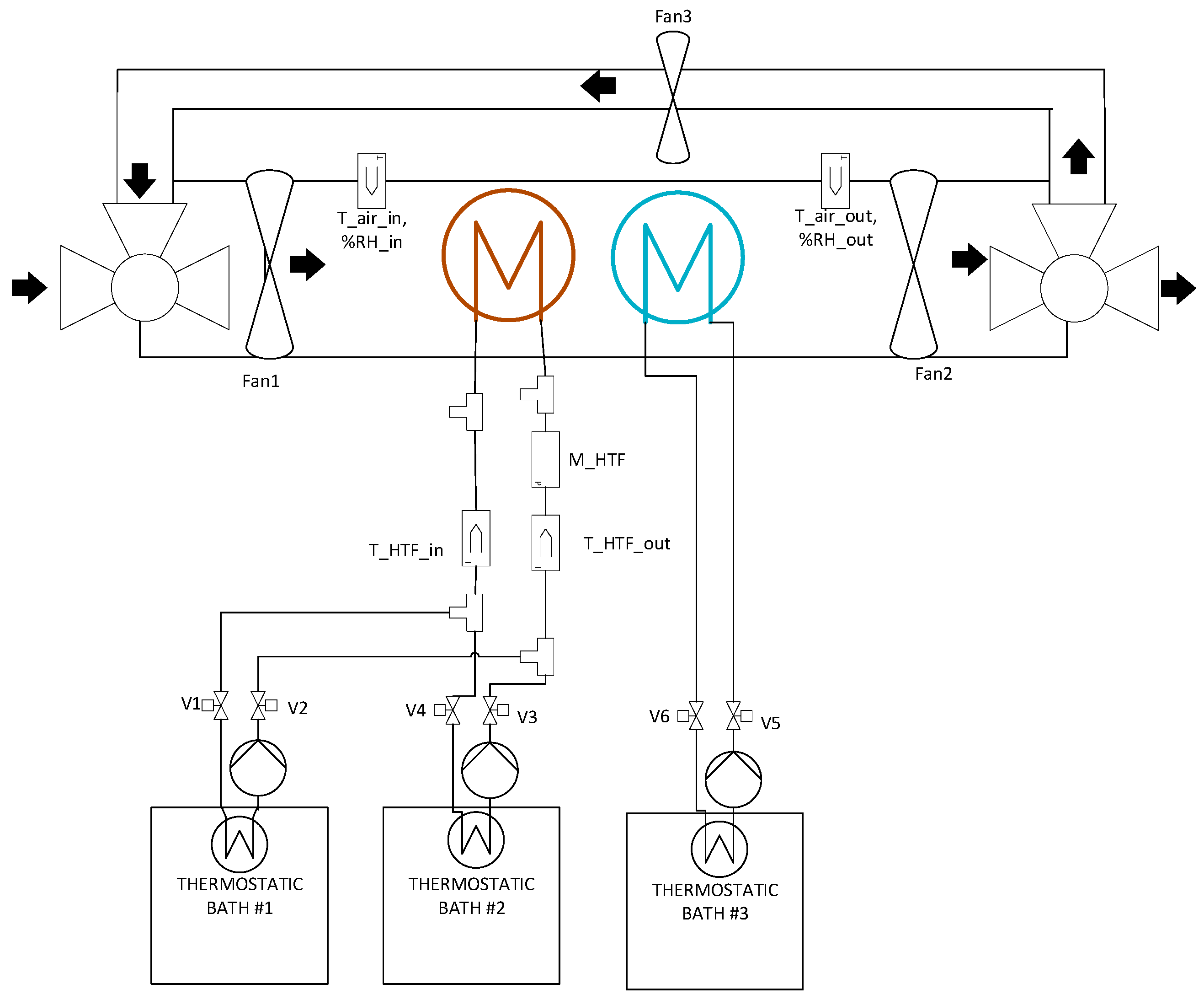
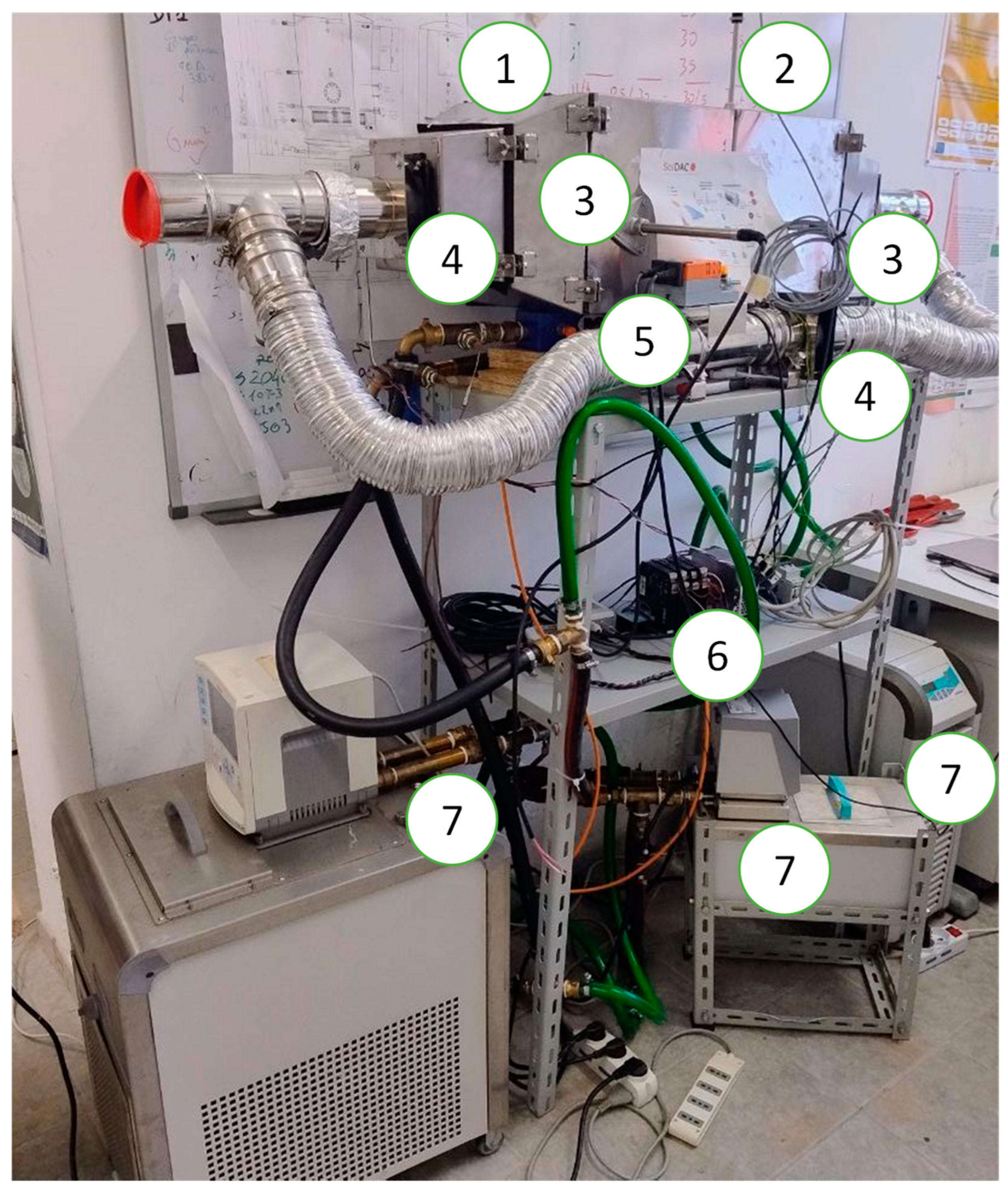
The HEX was tested in a dedicated bench specifically developed at CNR. The P&ID of the system is shown in Figure 2, whereas some pictures are shown in Figure 3. It mainly consists of a metallic duct, inside which the HEX under test is installed; two thermostatic baths for providing the temperature levels for adsorption and desorption; all the needed sensors; and the data acquisition system. The main duct also includes two tees at the inlet and outlet and a flexible pipe to allow air recirculation, and therefore better adsorption, to compensate for the dynamics of the material. The opening/closing of this branch is realized by means of automatic flow regulation valves equipped with stepper motors. The reason for the selection of such a configuration lies in the limitations of the actual sorption capacity measured when passing from material-scale to lab-scale adsorption in open systems. Indeed, the main cause for limited adsorption is the process dynamics, especially when using the selected composite material. This phenomenon was already highlighted in [29]. In adsorption wheels, this is mitigated by multiple recirculations of the air while the wheel is rotating. The proposed solution for the system tested in the lab was instead to add the recirculation pipe.
An additional component needed for the proper airflow management inside the duct was the fans. Different models were tested, and the final selection was a SUNON MA fan with a 230 V a.c. supply and 68 m3/h max airflow. Three fans were installed in the system: at the inlet of the duct, at the outlet, and in the recirculation branch.
Finally, as reported in several works in the literature [4], reaching the expected RH values with a single-stage adsorption process was not practically feasible and required the cooling of the adsorbent below the dew point under operating conditions or the use of a multi-stage process. To overcome this issue, it was decided to modify the configuration by adding a condensing unit after the adsorbent HEX, which was connected to a thermostatic bath kept at 3 °C.
The sensors installed and the measuring points and their accuracies are listed in Table 3.
The data acquisition system was realized by bus connection of analog and digital I/O modules from the company Seneca (Padova, Italy).

4. Results

4.1. Typical Trends During Adsorption and Desorption

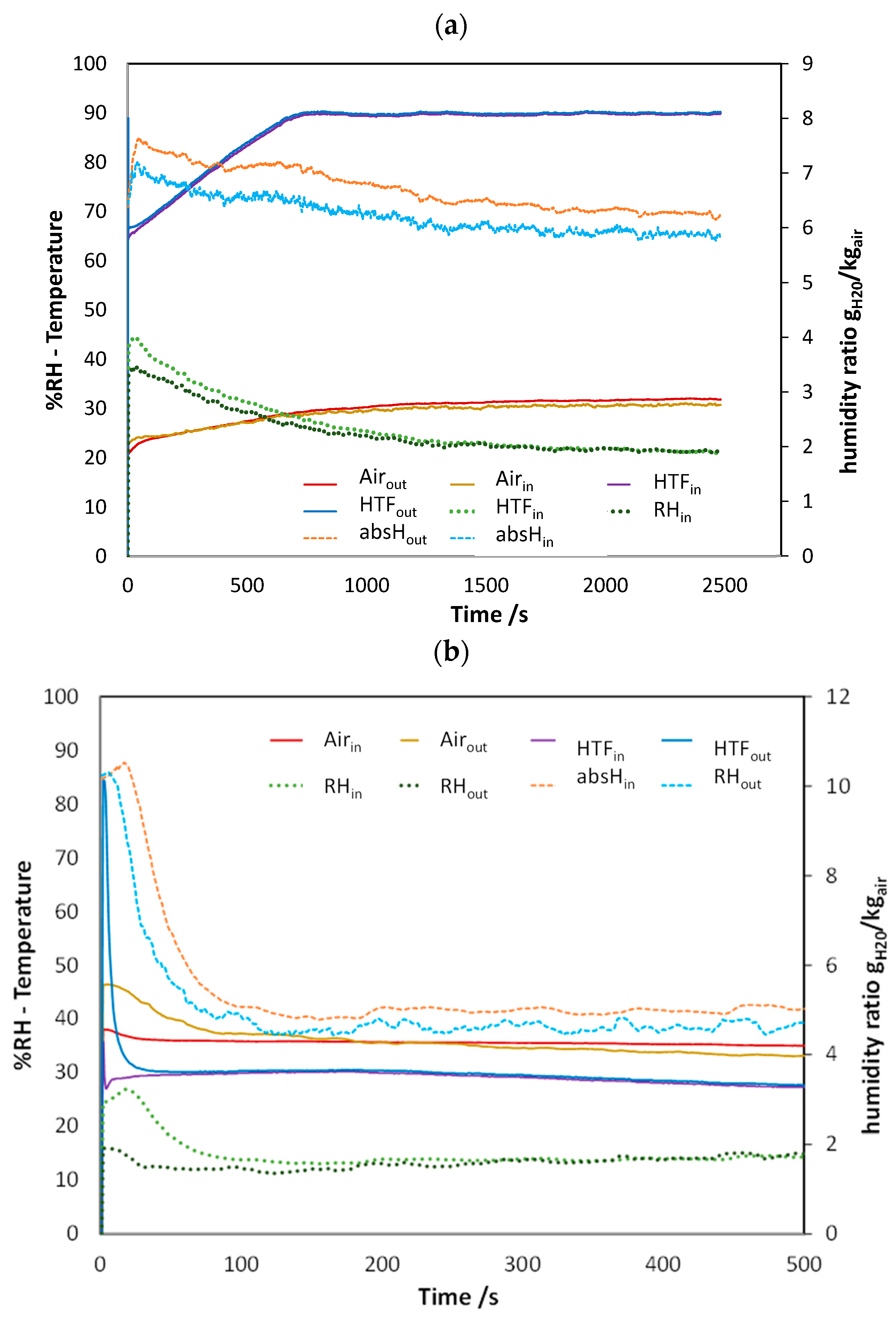
An example of the dynamic trends for desorption and adsorption measured during tests is given in Figure 4. It is worth mentioning that the notations “absHin” and “absHout” refer to the humidity ratio, which was calculated using CoolProp from the air temperature and air relative humidity. For the desorption process (Figure 4), it is possible to notice that as soon as the connection to the thermostatic bath with the high-temperature HTF is open, the humidity at the outlet increases, which is due to the water vapor released by the sorbent. It is interesting to notice what happens in more detail by looking at the orange and light blue curves, which represent the humidity ratio. It is clear that the majority of desorption occurs, more or less with a constant rate, for 500 s. The constant rate is due to the linear increase in the temperature of the HTF during this period: considering the shape of the isosters of Siogel in this range, this is in line with the theoretical expectations. After 1000 s, the material released almost all the water vapor and therefore, the inlet and outlet humidity ratios achieved the same value. To be more specific, after 1200 s, the %RH outlet was identical to the %RH in. This is due to the increasing temperature of the air within the wind tunnel (yellow line in the picture), which is heated by the material, which reached 85 °C.
Figure 4b shows the dynamic trends during adsorption. It is possible to notice that %RH out strongly decreased for the first seconds, and subsequently a constant difference between inlet and outlet was maintained. Let us consider the humidity ratio: it decreased for the first seconds and subsequently, a constant difference was maintained between the inlet and outlet, but with a negligible difference (<2 g/kg and with an average value of 10 g/kg). This can be more easily understood by looking at the red and yellow curves, which represent the temperature of the air. At the beginning of the adsorption process, the temperature of the air inlet was quite high, since it corresponded to the temperature during the desorption process. After 100 s, it reached the target value. It is worth mentioning that during previous tests carried out by the authors and not reported for brevity’s sake, it was verified that, without the cooling HEX, the time needed to cool down the air to the desired value was approx. 750 s.

4.2. Effect of Ambient Conditions

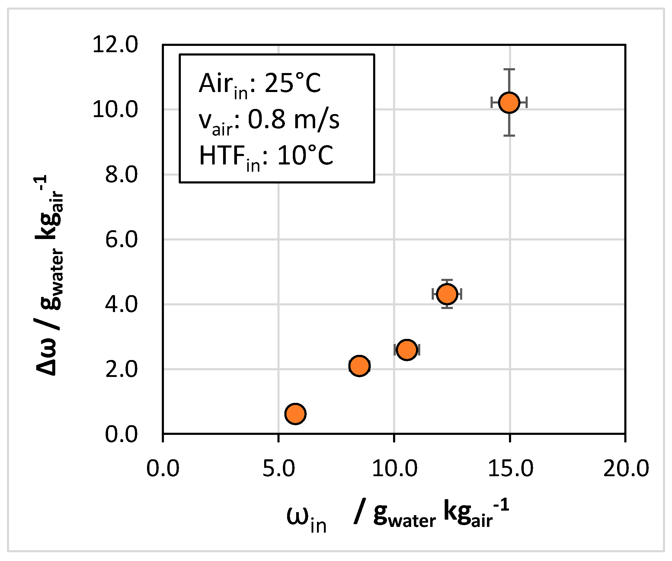
The first effect considered was the effect of the inlet temperature and relative humidity of the air to be processed. This parameter is important since it allows an understanding of whether the system is more suitable for humid or arid climates and what the limits are in these cases. The results reported in Figure 5 refer to the adsorption process since it corresponds to the useful effect exploitable. For a better evaluation of results, the tests refer to the same inlet air temperature and different relative humidity ratios. The results are visualized in terms of Δω, i.e., the difference between the humidity ratio of unprocessed air vs. the humidity ratio of the air at the outlet of the heat exchanger. It is possible to notice that there is a proportionality between the adsorption capacity, and therefore the achievable dehumidification effect, and the inlet humidity ratio, with a quadratic trend.
This result is particularly important since it indicates that to reach a deep dehumidification effect, in case a multi-stage system is to be foreseen, then the sorption process should represent the first stage, considering it allows a better operation when there is a higher inlet relative humidity. This is related to the higher adsorption potential for higher relative humidity ratios. For an inlet humidity ratio of 6.2 gwater/kgair, the achievable reduction in the humidity ratio was 0.6 g/kg, whereas for 15 gwater/kgair inlet, the reduction was 10 g/kg.

4.3. Effect of Operating Conditions

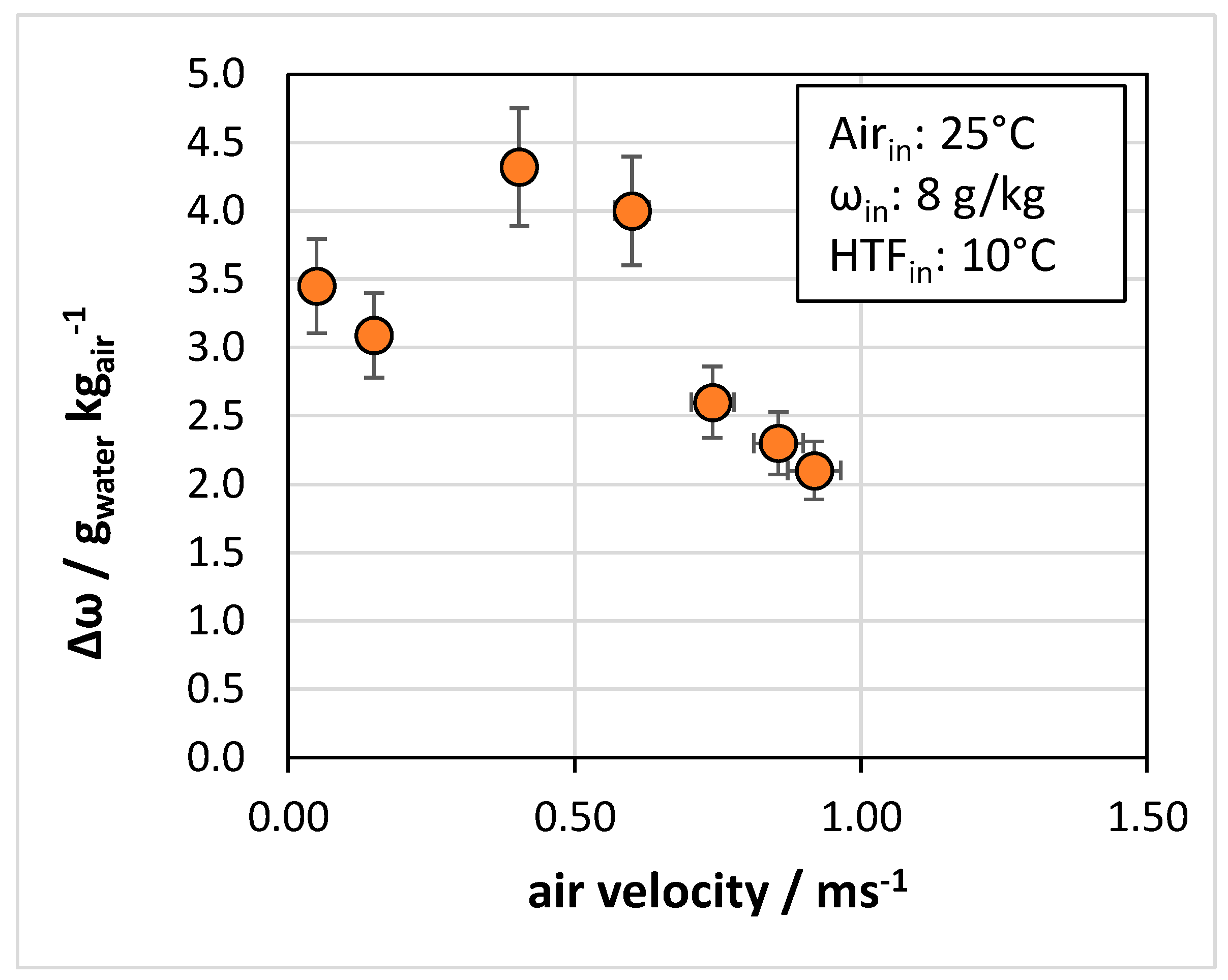
The operating conditions investigated were the effect of air velocity and the temperature of the heat transfer fluid (HTF). Figure 6 presents the effect of air velocity on the achievable reduction in the humidity ratio. The trend shows a first increase in the achievable Δω when passing from 0.1 m/s to 0.4–0.6 m/s and a subsequent decrease afterward. This trend can be explained by considering that for very low velocities of the air, the proper passage of air in the HEX was not fully achieved, especially in areas where there was a thicker layer of the sorbent, as will be detailed in the next section. However, when the air velocity was too high, i.e., >0.6 m/s for the present case, the contact time between the air and the sorbent was not sufficient for the adsorption process.
This is mostly due to the dynamic behavior of the composite sorbent during the process.
It is, therefore, clear that there exists a trade-off between the velocity needed to overcome the pressure drops in the HEX and the kinetic characteristics of the sorbent. It is worth mentioning that all the tests reported here were realized with the second stage active, i.e., with the cooling HEX connected to the thermostatic bath at 3 °C.
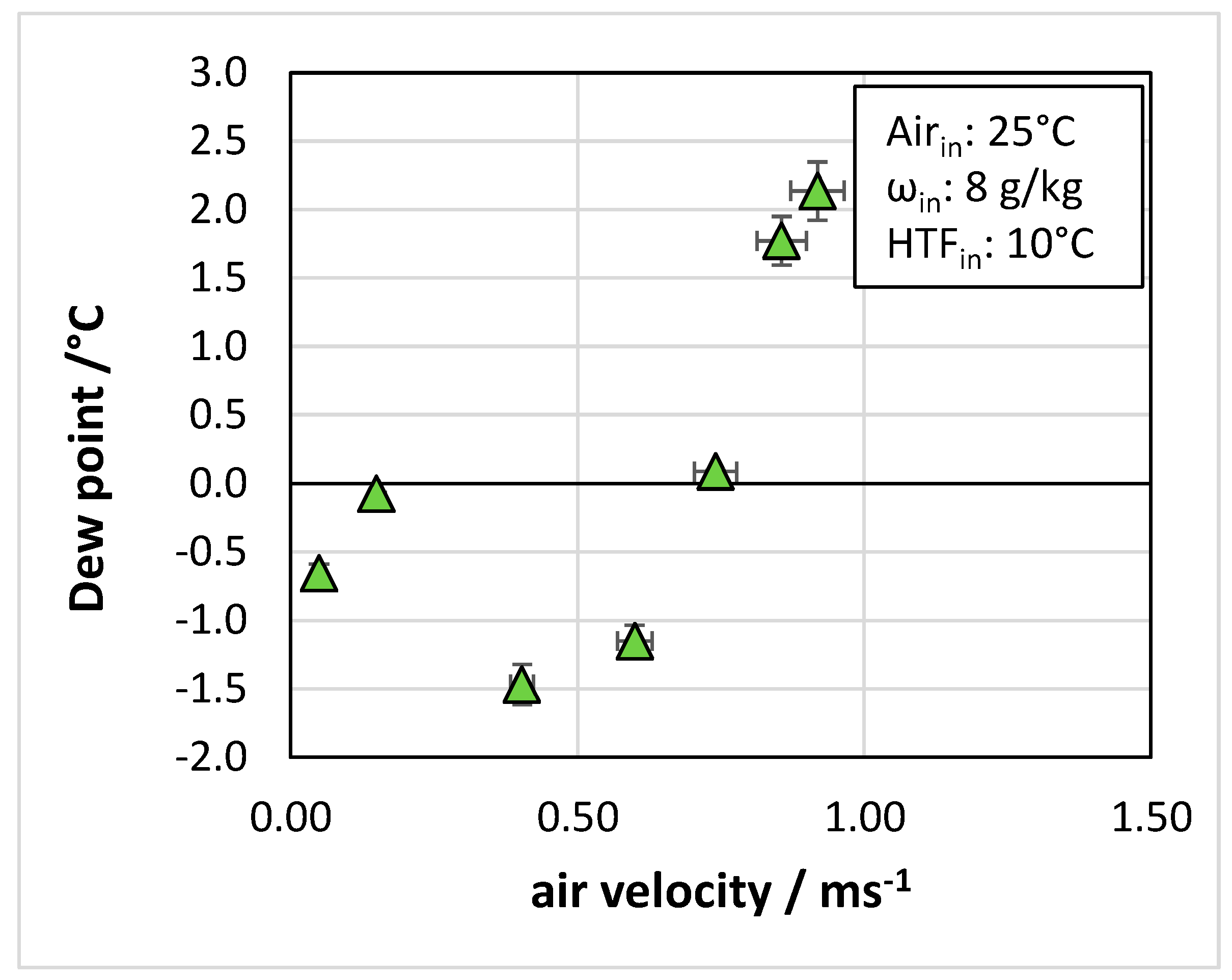
Figure 7 presents the dew point of air for the same tests. The minimum dew point achieved was −1.5 °C for the test at 0.40 m/s air velocity.
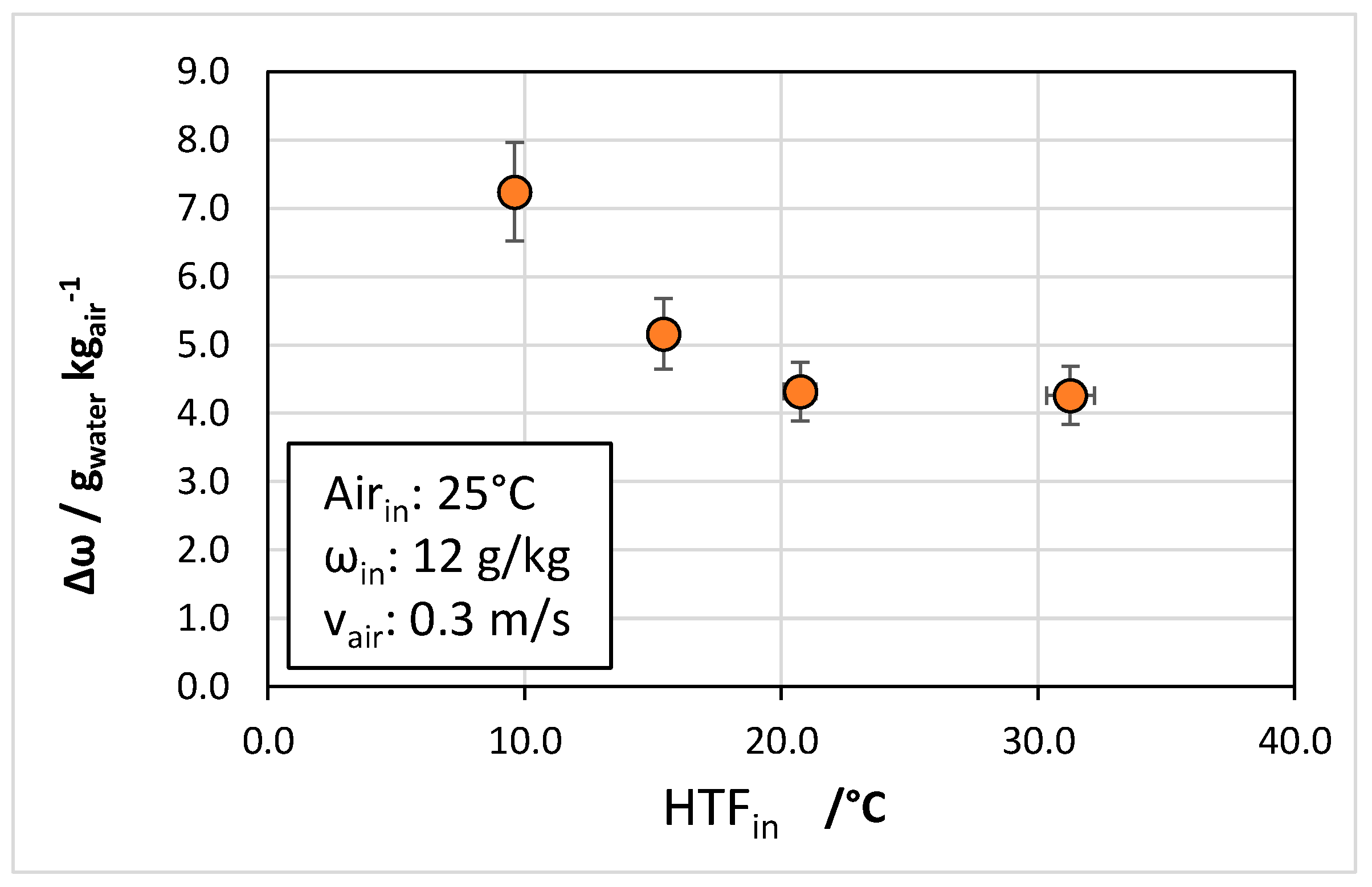
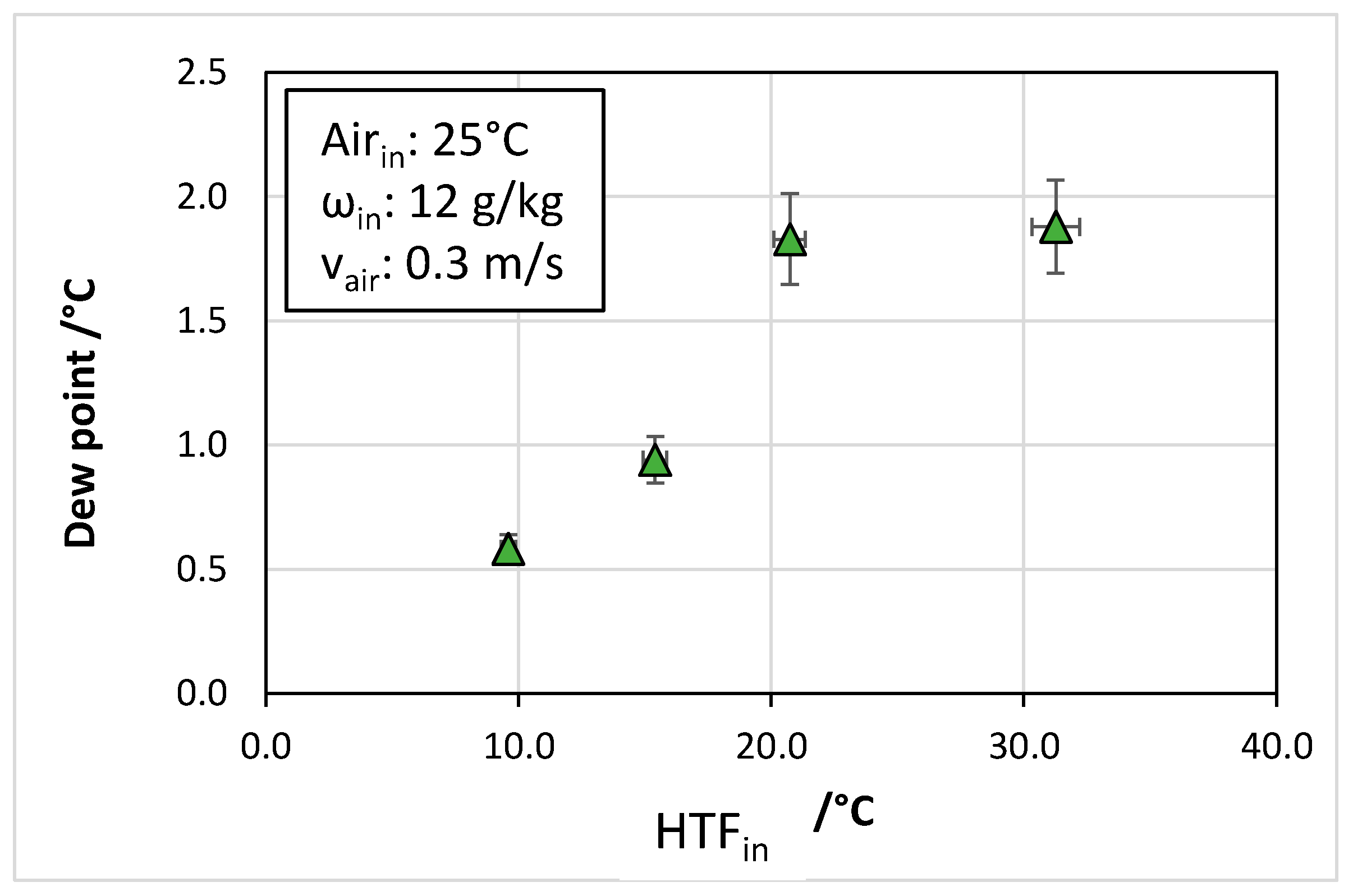
Figure 8 and Figure 9 show the results of the tests carried out at different inlet temperatures of the HTF. Indeed, it is well known that the adsorption capacity increases with the reduced temperature of the adsorbent, which translates, from an engineering perspective, into a lower temperature for the cooling fluid. As will be better explained in the next section, a dedicated analysis was carried out to verify that the cooling of the sorbet occurs in a short time to ensure that the adsorption heat is properly dissipated. The results in Figure 8 refer to the reduction in the humidity ratio as a function of the HTF inlet. The better results are achieved for an inlet temperature of 10 °C with a quadratic reduction. Above 20 °C, a plateau is reached. HTF inlet temperatures above 20 °C were investigated since they correspond to the case where water at ambient temperature can be used for cooling without the need for extra energy expenses for producing chilled water. However, it is clear that compared to the case of HTF inlet of 10 °C, when Δω = 7 g/kg was achieved, temperatures above 20 °C only allowed Δω = 4 g/kg, i.e., 40% lower adsorption capacity.
The same trend is observed for the dew point of the outlet air, reported in Figure 9: whereas for an HTF inlet of 10 °C the dew point was 0.5 °C, for the temperatures above 20 °C the dew point increased to 2.0 °C.

5. Discussion

The main goal of the developed HEX was to demonstrate that with a proper combination of design and operating parameters, it is possible to achieve good heat and mass transfer, and therefore relatively fast cycling, while maintaining high moisture removal capacity. To this aim, dedicated activities and analyses were devoted to the calculation of heat and mass transfer in the HEX under various operating conditions, which are described in the following sections.

5.1. Verification of Heat Transfer in the HEX

A preliminary activity that was carried out was the verification of proper heat uniformity in the HEXs. To do so, an IR camera, model FLIR A35, was used.
The first test was carried out on the empty HEX (no sorbent inside) to verify the correct temperature distribution and the absence of temperature gradients. The HEX was heated from ambient temperature to 70 °C by connection to the thermostatic bath.
The results are shown in Figure 10. It is possible to notice that the heat transfer fluid distribution in the flat tubes (horizontal lines in yellow colors) is uniform and the desired temperature is reached in less than 15 s, and, after 25 s, most of the finned pack has reached the temperature of the heat transfer fluid.
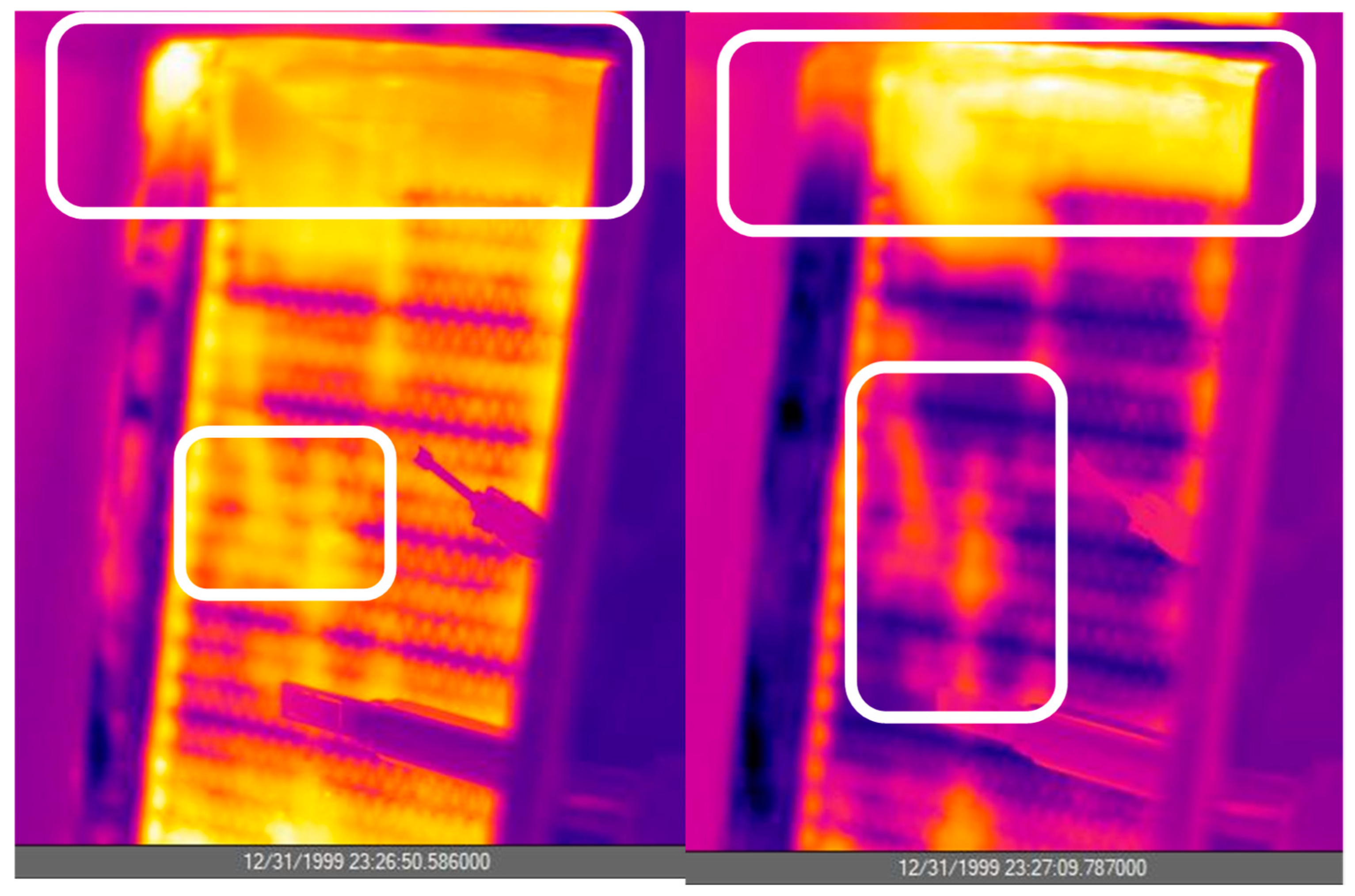
Afterward, an entire cycle was recorded with the IR camera. Adsorption was carried out at 20 °C and desorption at 70 °C. Some pictures from the IR camera are shown in Figure 11. The main considerations that can be drawn are that the full heating of the HEX with the material requires 30 to 50 s and the complete cooling of the HEX requires 30 to 60 s. Such values can be considered acceptable since they are less than 10% of the overall time for adsorption/desorption.
A spot with lower heat transfer can be identified at the top, which is due to the imperfect airstream in the top part of the wind tunnel (see Figure 12).
Some spots on the external part of the HEX have accumulated material and can be identified, requiring more time for heating/cooling. This is mostly due to the imperfect filling of the HEX, but it is possible to notice that these are small areas, and therefore, it can be considered that the overall distribution of the material and the heat transfer are satisfactory.
One important conclusion from such activity is that the minimum cycle time, just from a heat transfer point of view, is 160 s without any consideration of mass transfer and adsorption dynamics.

5.2. Heat Transfer Analysis

The heat transfer analysis carried out consisted of the calculation of the overall heat transfer coefficient for the HEX under various operating conditions. The heat transfer coefficient can be easily calculated as follows:
U = Q a v ˙ L M T D A    
where A is the heat transfer surface, LMTD is the logarithmic mean temperature difference, and Q a v ˙ can be calculated as the average of the powers measured on the air side and water side:
Q ˙ a v = a v e r a g e ( m ˙ w a t e r c p w a t e r ( T w a t e r i n T w a t e r o u t ) ,   m ˙ a i r c p a i r ( T a i r i n T a i r o u t )  
The logarithmic mean temperature difference can be calculated as follows:
L M T D = T w a t e r i n T a i r o u t   ( T w a t e r o u t T a i r i n ) l n ( T w a t e r i n   T a i r o u t T w a t e r o u t   T a i r i n )  
In turn, the heat transfer coefficient can be separated into three contributions: convection on the air side (hext), convection on the water side (hint), and conduction in the metal:
1 U = 1 h i n t + δ m e t a l λ m e t a l + 1 h e x t
where λ m e t a l is the thermal conductivity of the metal and δ m e t a l is the fin thickness.
Once the contributions are calculated, it is easy to verify, for the case examined, that the highest resistance is on the air side and therefore:
1 U 1 h e x t
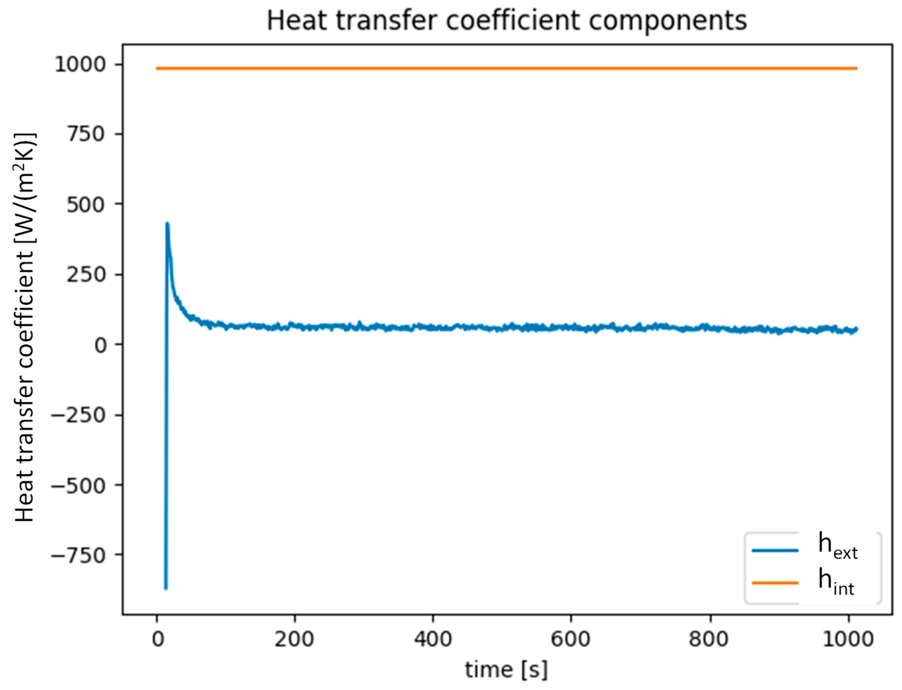
An example of results can be seen in Figure 13 for one test with an HTF inlet temperature of 10 °C and an initial humidity ratio of 8 g/kg.
The operating parameter yielding the largest influence on the heat transfer coefficient is the velocity of air since it affects the heat exchange on the air side. The effect of air velocity on the heat transfer coefficient is shown in Figure 14 for the same set of tests presented in Figure 6. It is possible to notice that for very low air velocities, the heat transfer coefficient is in the range of 50 W/(m2 K), whereas it increases to approximately 130 W/(m2 K) for velocities of 0.4 m/s and above. It remains constant with increased velocity once this limit has been reached due to the intrinsic characteristic of the sorbent material, which has a thermal conductivity of 0.2 W/(mK), and to the non-optimal distribution of airflow inside the channel, which was not specifically studied from the fluid-dynamics perspective. Overall, the UA values measured are in the range of 80–130 W/K, which is approx. 25% higher than the average values for commercial finned flat tube HEX reported in [28], thus indicating a good efficiency of the heat exchanger compared to the state of the art.
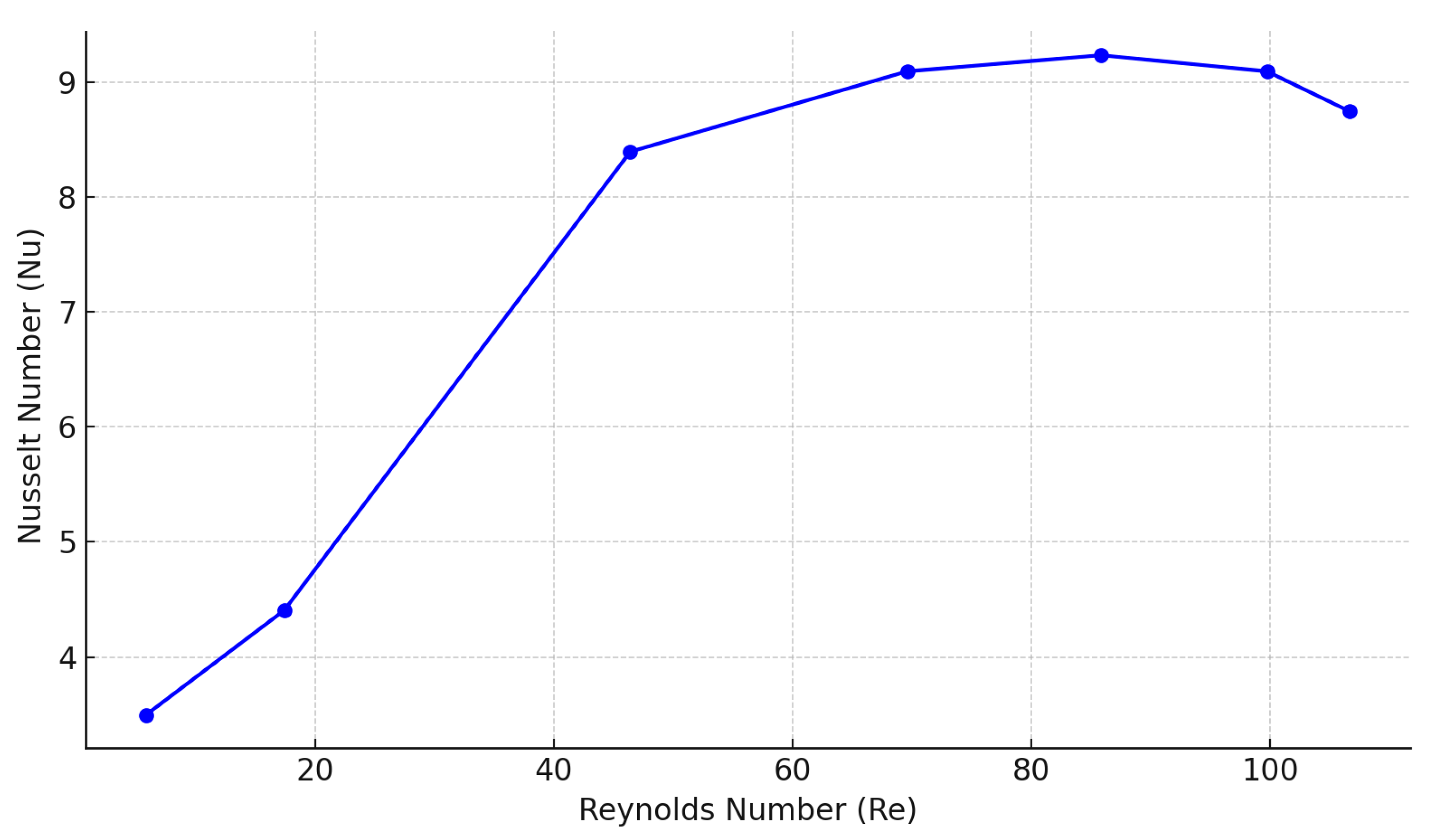
However, as can be noticed from the comparison between Figure 14 and Figure 6, even if at higher air velocities the heat transfer coefficient is more or less constant, this does not correspond to an increased sorption capacity. As previously mentioned, this is partly due to the dynamics of the adsorption process, but it might also be ascribed to fluid dynamic reasons. For the tested conditions, the correlation between the Reynolds number and the Nusselt number was calculated and it is shown in Figure 15. The curve shows an initial increase in Nu with Re, followed by a plateau starting around Re ≈ 70–100, which corresponds to air velocities of 0.75 to 0.80 m/s. This behavior indicates the onset of a heat transfer performance limit, likely due to geometric and flow constraints of the heat exchanger.

5.3. Mass Transfer Analysis

The mass transfer coefficient can be calculated according to the data reduction procedure described in [23]. The overall mass transfer coefficient is expressed as a function of the mass transfer rate and the driving force, which is the difference in the humidity ratio of the air and the one at equilibrium:
K t o t a l = F v A ( ω a i r ω e q )
Fv is the mass transfer rate, calculated in turn from the mass flow rate of air and the humidity ratio of air:
F v = m ˙ a i r ( ω a i r i n   ω a i r o u t )
The humidity ratio at equilibrium can be calculated as follows:
ω e q = M v P v / M d a P d a
where Pv is the relative water vapor pressure at dry bulb temperature and relative humidity. It was calculated using the psychrolib package in Python 3.12. Pda is the pressure of dry air.
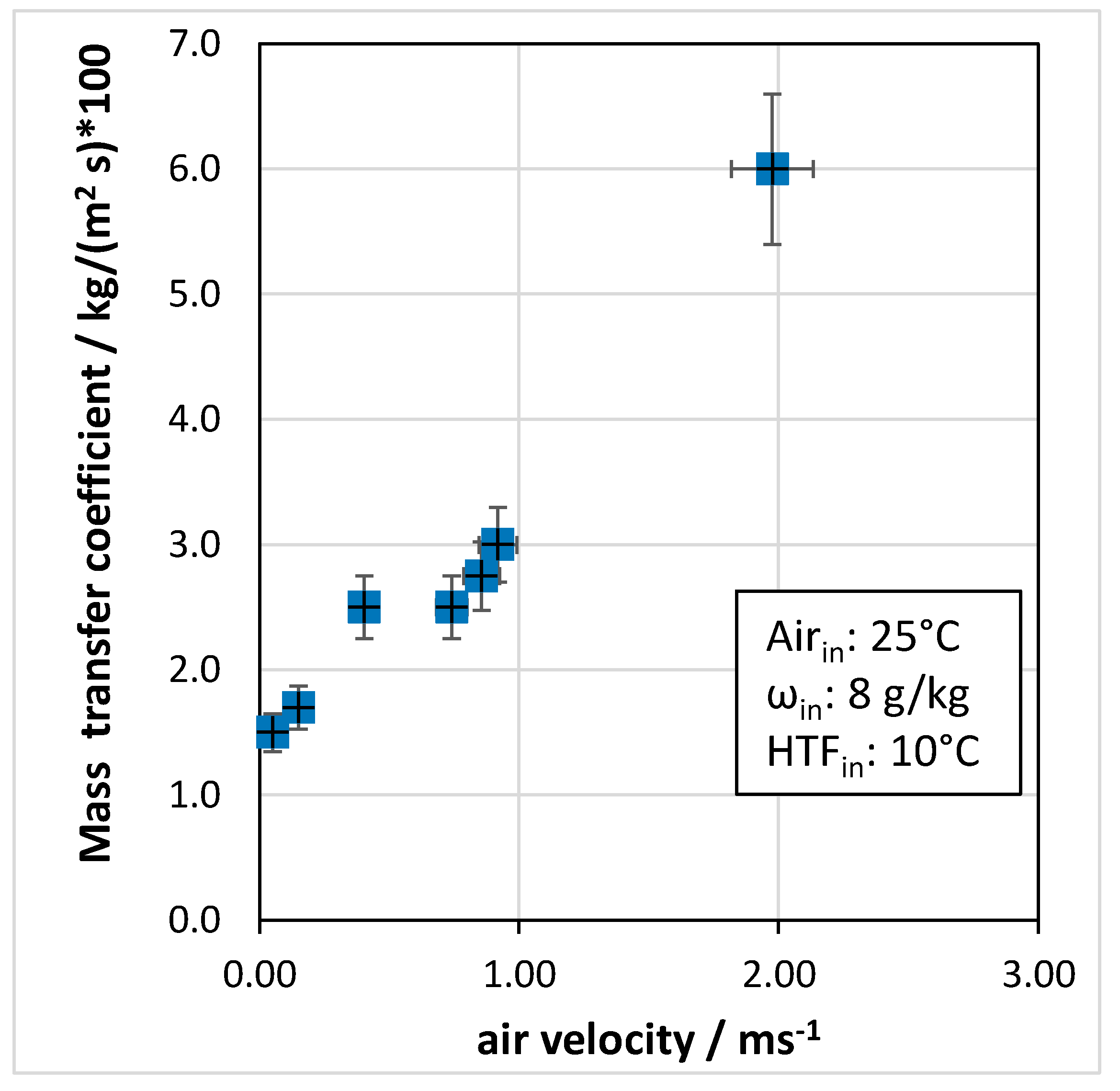
Figure 16 shows the effect of air velocity on the mass transfer coefficient. There is a clear improvement in the mass transfer coefficient with air velocity, as remarked by the test carried out at 1.98 m/s. However, as previously mentioned, increasing the flow rate of air does not allow for a proper time of contact between the air and the adsorbent, and, as a final result, this reduces the sorption capacity. Considering the tests in the range of 0.1 to 1 m/s, it is possible to notice that the mass transfer coefficient is in the range of 0.025–0.035 kg/(m2 s), which is twice the value reported for the packed bed heat exchanger in [23]. This further remarks that the design of the HEX is suitable and that an advancement compared to the state of the art has already been achieved.
To deepen the analysis of mass transfer during the dehumidification process, the results obtained were used to calculate the Sherwood number (Sh) as follows:
S h = K t o t a l Φ   ρ D h
where Φ is the molecular mass diffusion, that for water vapor in the air, was considered equal to 2.5 × 10⁻⁵  m2/s [30]. The values obtained range from 60 to 100, thus indicating a mass transfer-dominated problem. The comparison between Nusselt and Sherwood numbers suggests that heat and mass transfer are not fully coupled in this configuration. While heat transfer tends to plateau with increasing air velocity, mass transfer remains more sensitive. This mismatch is indeed common in conventional dehumidification heat exchangers and points to a potential avenue for structural optimization of the exchanger.

5.4. Comparison with Other Studies in the Literature

In order to evaluate the significance of the proposed solution, a comparison was made with relevant works available in the literature and presenting similar applications and materials.
In [23], the authors report the heat and mass transfer coefficients for a coated heat exchanger with a felt of silica gel and inert particles. The system is tested under controlled conditions, with a desorption temperature of around 50 °C and an adsorption temperature of 0 °C (using brine as heat transfer fluid). The air inlet was 2 °C, with 80% RH. The heat transfer coefficients measured are in the order of 10 to 20 W/(m2 K), whereas the average mass transfer coefficients measured range from 0.010 to 0.040 kg/(m2 s). Compared to the current work, the heat transfer coefficients are significantly lower, whereas mass transfer coefficients are in line with the presented heat exchanger. It is worth noticing, though, that the heat exchanger examined in this work is a packed bed rather than a coated one, which further remarks the results achieved.
In [31], the authors present a 3D model for a coated heat exchanger with silica gel as a desiccant. Simulations are carried out considering air temperatures in the range of 15 °C to 40 °C, air velocities of 0.25 to 2.75 m/s, humidity ratios of 7.3 to 24 g/kg, and cooling water temperatures of 10 °C to 35 °C, thus, more comparable with the current study compared to those above mentioned. The results of the simulations indicate that heat transfer coefficients in the range of 30 to 120 W/(m2 K) can be achieved, which is in line with the experimental findings of our work. Mass transfer coefficients simulated are in the range of 0.010 to 0.040 kg/(m2 s), thus, again in line with the experiments presented here, which allowed us to increase the max mass transfer coefficient by 30% compared to the simulated case.

6. Conclusions

The present paper analyzes the experimental performance of a plate-fin water–air heat exchanger filled with silica gel/calcium chloride composite material for the possible application as part of a deep dehumidification system. The experimental activity was carried out to evaluate the effect of ambient conditions and operating parameters on the achievable effect. The following main conclusions can be drawn:
  • Regarding ambient conditions, it was found that the lower the inlet relative humidity, the lower the reduction in the humidity ratio between the inlet and outlet.
  • In terms of operating parameters, the most influential was the velocity of air passing through the heat exchanger: for the tested system, an optimal range of 0.4 to 0.6 m/s was identified.
  • The temperature of the cooling fluid also played an important role, with the dew point of outlet air increasing from 0 °C to 2 °C when the heat transfer fluid temperature passed from 10 °C to 30 °C.
  • A detailed heat and mass transfer analysis was carried out on the heat exchanger. The IR camera visualization technique revealed that within 10 s, the heat exchanger was cooled/heated to the heat transfer fluid temperature. On the air side, the most important parameter for heat transfer was air velocity.
  • Heat transfer coefficients in the range of 80–140 W/(m2 K) were measured. In terms of mass transfer, with increasing air velocity, the mass transfer coefficient passed from 0.015 to 0.060 kg/(m2 s).
The results reported indicate that the system can outperform, especially in terms of heat and mass transfer, most lab-scale tested components for air dehumidification. The comparison with other systems in the literature indicated that up to 30% increased mass transfer coefficient was achieved and up to seven times higher heat transfer coefficient was measured.

Author Contributions

Conceptualization, V.P. and V.B.; methodology, V.P. and V.B.; validation, A.F., F.C. and D.L.R.; formal analysis, V.P.; investigation, A.F., F.C. and D.L.R.; resources, V.B.; data curation, V.P., A.F. and V.B.; writing—original draft preparation, V.P.; writing—review and editing, A.F. and V.B.; visualization, V.P. and V.B.; supervision, V.P.; project administration, V.P.; funding acquisition, V.P. All authors have read and agreed to the published version of the manuscript.

Funding

This research was funded by the European Commission under the Horizon Europe Programme under Grant Agreement No. 101069359 (SolDAC).

Data Availability Statement

The original contributions presented in the study are included in the article, further inquiries can be directed to the corresponding author.

Conflicts of Interest

The authors declare no conflicts of interest.

Nomenclature

The following nomenclature and abbreviations are used in this manuscript:
Aarea, m2
cpspecific heat, kJ/(kg K)
Fvolumetric flow rate, m3/s
hheat transfer coefficient for convection, W/(m2 K)
Kmass transfer coefficient, kg (m2 s)
m ˙ mass flow rate, kg/s
MMolar mass, kg/mol
Ppressure, Pa
Q ˙ power, W
Ttemperature
Uheat transfer coefficient, W/(m2 K)
δfin thickness, mm
λthermal conductivity, W/(m K)
ωhumidity ratio, g/kg
Subscripts
avaverage
dadry air
eqequilibrium
extexternal
ininlet
intinternal
outoutlet
vvapor
Abbreviations
HEXheat exchanger
HTFheat transfer fluid
LMTDlogarithmic mean temperature difference
RHrelative humidity
SGsilica gel

References

  1. Xie, M.; Chen, E.; Huang, G.; Jia, T.; Dai, Y. Recent Advancements in Deep Dehumidification Technology: A Review. Renew. Sustain. Energy Rev. 2025, 211, 115321. [Google Scholar] [CrossRef]
  2. Lao, M.; Lin, J.; Mikšík, F.; Thu, K.; Miyazaki, T. Performance and Design Analyses of Various Configurations of Dew Point Evaporative Cooling-Based Desiccant Air-Conditioning (DAC) Systems for Hot and Humid Conditions. Int. J. Air-Cond. Refrig. 2022, 30, 12. [Google Scholar] [CrossRef]
  3. Venegas, T.; Qu, M.; Wang, L.; Liu, X.; Gluesenkamp, K.; Gao, Z. Review of Liquid Desiccant Air Dehumidification Systems Coupled with Heat Pump: System Configurations, Component Design, and Performance. Energy Build. 2023, 279, 112655. [Google Scholar] [CrossRef]
  4. Zhang, Q.; Tu, R.; Liu, M. Performance Analyses and Optimization Studies of Desiccant Wheel Assisted Atmospheric Water Harvesting System under Global Ambient Conditions. Energy 2023, 283, 128477. [Google Scholar] [CrossRef]
  5. Evron, Y.; Gommed, K.; Grossman, G. Efficient Deep Dehumidification Hybrid Air Conditioning System. Int. J. Refrig. 2019, 105, 50–58. [Google Scholar] [CrossRef]
  6. Fang, S.; Xu, Z.; Yao, Y.; Zhou, X.; Zhang, H.; Gan, H.; Zhi, X.; Qiu, L.; Wang, K. Compression Heat Self-Utilisation Systems with Cascade Deep Dehumidification for Industrial Compressor Energy Saving. J. Clean. Prod. 2024, 473, 143493. [Google Scholar] [CrossRef]
  7. Guan, B.; Liu, X.; Zhang, T.; Ma, Z.; Chen, L.; Chen, X. Experimental and Numerical Investigation of a Novel Hybrid Deep-Dehumidification System Using Liquid Desiccant. Energy Convers. Manag. 2019, 192, 396–411. [Google Scholar] [CrossRef]
  8. Guan, B.; Liu, X.; Zhang, T. On the Importance of Air-Solution Flow Rate Matching in Liquid-Desiccant Deep-Dehumidification System. Int. J. Heat Mass Transf. 2021, 164, 120614. [Google Scholar] [CrossRef]
  9. Fang, S.; Xu, Z.; Zhang, H.; Rong, Y.; Zhou, X.; Zhi, X.; Wang, K.; Markides, C.N.; Qiu, L. High-Performance Multi-Stage Internally-Cooled Liquid Desiccant Dehumidifier for High Gas–Liquid Flow Ratios. Energy Convers. Manag. 2021, 250, 114869. [Google Scholar] [CrossRef]
  10. Wen, T.; Lu, L.; Zhong, H.; Dong, C. Experimental and Numerical Study on the Regeneration Performance of LiCl Solution with Surfactant and Nanoparticles. Int. J. Heat Mass Transf. 2018, 127, 154–164. [Google Scholar] [CrossRef]
  11. Bai, H.; Zhu, J.; Chu, J.; Chen, X.; Cui, Y.; Yan, Y. Influences of the Mixed LiCl-CaCl2 Liquid Desiccant Solution on a Membrane-Based Dehumidification System: Parametric Analysis and Mixing Ratio Selection. Energy Build. 2019, 183, 592–606. [Google Scholar] [CrossRef]
  12. Su, X.; Geng, Y.; Huang, L.; Li, S.; Wang, Q.; Xu, Z.; Tian, S. Review on Dehumidification Technology in Low and Extremely Low Humidity Industrial Environments. Energy 2024, 302, 131793. [Google Scholar] [CrossRef]
  13. Bonaccorsi, L.; De Antonellis, S.; Tomaino, G.; Freni, A.; Malara, A.; Frontera, P.; Fotia, A. Electrospun Hybrid Microfibers for Desiccant Cooling/Air Dehumidification. Appl. Therm. Eng. 2025, 258, 124524. [Google Scholar] [CrossRef]
  14. Calabrese, L.; Mastronardo, E.; Piperopoulos, E.; Scionti, G.; De Antonellis, S.; Freni, A.; Milone, C. Effect of Alternating Humidity and Dryness on the Durability of Adsorbent Sheets Used in Open Cycle Adsorption Processes. Polym. Degrad. Stab. 2025, 234, 111201. [Google Scholar] [CrossRef]
  15. Mastronardo, E.; De Antonellis, S.; Freni, A.; Milone, C.; Calabrese, L. Stability of Adsorbent Sheets Under Accelerated-Aging Tests for Open-Cycle Adsorption Processes. Energies 2025, 18, 1023. [Google Scholar] [CrossRef]
  16. Zhang, Q.; Li, Y.; Zhang, Q.; Ma, F.; Lü, X. Application of Deep Dehumidification Technology in Low-Humidity Industry: A Review. Renew. Sustain. Energy Rev. 2024, 193, 114278. [Google Scholar] [CrossRef]
  17. Zeng, Y.; Woods, J.; Cui, S. The Energy Saving Potential of Thermo-Responsive Desiccants for Air Dehumidification. Energy Convers. Manag. 2021, 244, 114520. [Google Scholar] [CrossRef]
  18. Askalany, A.A.; Uddin, K.; Saha, B.B.; Sultan, M.; Santori, G. Water Desalination by Silica Supported Ionic Liquid: Adsorption Kinetics and System Modeling. Energy 2022, 239, 122069. [Google Scholar] [CrossRef]
  19. Guan, B.; Liu, X.; Zhang, T. Modification of Analytical Solutions of Coupled Heat and Mass Transfer Processes in Liquid Desiccant Dehumidifier for Deep Dehumidification. Int. J. Heat Mass Transf. 2021, 165, 120728. [Google Scholar] [CrossRef]
  20. Cheng, J.-H.; Wang, Z.-Y.; Cao, X.; Li, X.-Y.; Zhang, C.-L. Achieving Deep Dehumidification through a Heat Pump-Boosted Desiccant Wheel System. Energy Convers. Manag. 2024, 313, 118604. [Google Scholar] [CrossRef]
  21. Tu, R.; Hwang, Y. Efficient Configurations for Desiccant Wheel Cooling Systems Using Different Heat Sources for Regeneration. Int. J. Refrig. 2018, 86, 14–27. [Google Scholar] [CrossRef]
  22. Asadi, A.; Roshanzadeh, B. Improving Performance of Two-Stage Desiccant Cooling System by Analyzing Different Regeneration Configurations. J. Build. Eng. 2019, 25, 100807. [Google Scholar] [CrossRef]
  23. Li, Z.; Michiyuki, S.; Takeshi, F. Experimental Study on Heat and Mass Transfer Characteristics for a Desiccant-Coated Fin-Tube Heat Exchanger. Int. J. Heat Mass Transf. 2015, 89, 641–651. [Google Scholar] [CrossRef]
  24. Liu, L.; Huang, H.; Li, J.; Bai, Y.; He, Z.; Deng, L.; Gao, T.; Kubota, M.; Kobayashi, N. Deep Dehumidification Characteristics of a Silica Gel Coated Cross-Flow Heat Exchanger with a Circulating Blowing Loop. Energy Build. 2024, 325, 114991. [Google Scholar] [CrossRef]
  25. Liu, J.; Sun, C.; Chen, Q. Experimental Study of Desiccant-Coated Heat Exchangers for Deep Dehumidification. Energy Build. 2024, 319, 114554. [Google Scholar] [CrossRef]
  26. Brancato, V.; Gordeeva, L.G.; Sapienza, A.; Palomba, V.; Vasta, S.; Grekova, A.D.; Frazzica, A.; Aristov, Y.I. Experimental Characterization of the LiCl/Vermiculite Composite for Sorption Heat Storage Applications. Int. J. Refrig. 2019, 105, 92–100. [Google Scholar] [CrossRef]
  27. Sapienza, A.; Frazzica, A.; Freni, A.; Aristov, Y. Dynamics of Adsorptive Systems for Heat Transformation; Springer Briefs in Applied Sciences and Technology; Springer International Publishing: Cham, Switzerland, 2018. [Google Scholar]
  28. Grekova, A.D.; Tokarev, M.M.; Aristov, Y.I. On the Use of Finned Flat-Tube Heat Exchangers for Adsorptive Heat Storage and Transformation. J. Energy Storage 2024, 84, 110973. [Google Scholar] [CrossRef]
  29. Aristov, Y.I.; Gordeeva, L.G. Combining the Psychrometric Chart of Humid Air with Water Adsorption Isosters: Analysis of the Ventireg Process. Energy 2021, 239, 122278. [Google Scholar] [CrossRef]
  30. Massman, W.J. A Review of the Molecular Diffusivities of H2O, CO2, CH4, CO, O3, SO2, NH3, N2O, NO, and NO2 in Air, O2 and N2 near STP. Atmos. Environ. 1998, 32, 1111–1127. [Google Scholar] [CrossRef]
  31. Priyadarshi, G.; Kiran Naik, B. Experimental and Numerical Studies on Moisture Adsorption/Desorption Characteristics across the Circular Fin Tube Desiccant Coated Heat Exchanger. Therm. Sci. Eng. Prog. 2024, 53, 102755. [Google Scholar] [CrossRef]
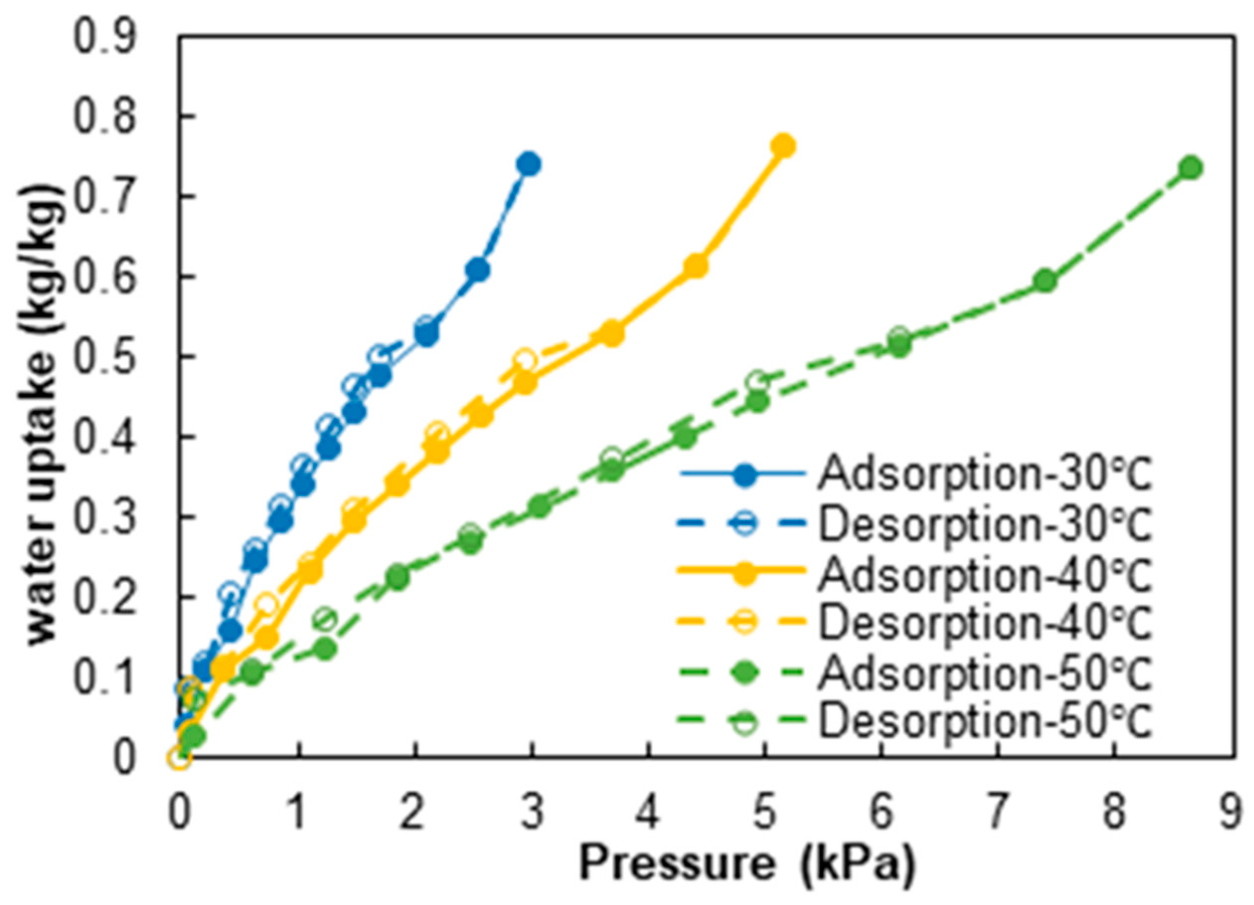
Figure 1. Adsorption isotherms for the SG-35% CaCl2 composite.
Energies 18 02418 g001
Figure 2. P&ID of the tested system.
Energies 18 02418 g002
Figure 3. Testing rig for the heat exchangers for deep dehumidification: 1—main duct; 2—air velocity sensor; 3—thermo-hygrometers; 4—fans; 5—automatic valve; 6—data acquisition system; 7—thermostatic baths.
Energies 18 02418 g003
Figure 4. Dynamic trends during desorption (a) and adsorption (b).
Energies 18 02418 g004
Figure 5. Effect of ambient temperature and humidity on the performance of the heat exchanger.
Energies 18 02418 g005
Figure 6. Effect of air velocity on the reduction in the humidity ratio.
Energies 18 02418 g006
Figure 7. Effect of air velocity on the dew point of outlet air.
Energies 18 02418 g007
Figure 8. Effect of heat transfer fluid temperature on the reduction in the humidity ratio.
Energies 18 02418 g008
Figure 9. Effect of heat transfer fluid temperature on the dew point of outlet air.
Energies 18 02418 g009
Figure 10. Heat uniformity in the adsorber HEX. Pictures of heating test with IR camera.
Energies 18 02418 g010
Figure 11. Heat uniformity during a desorption/adsorption cycle. Pictures from IR camera.
Energies 18 02418 g011
Figure 12. Heat uniformity during a desorption/adsorption cycle. Pictures from IR camera—details of the adsorption process.
Energies 18 02418 g012
Figure 13. Example of heat transfer coefficient calculation.
Energies 18 02418 g013
Figure 14. Effect of air velocity on the heat transfer coefficient.
Energies 18 02418 g014
Figure 15. Variation in the Nusselt number as a function of the Reynolds number for different airflow velocities across the heat exchanger.
Energies 18 02418 g015
Figure 16. Effect of air velocity on mass transfer coefficient.
Energies 18 02418 g016
Table 1. Summary of the integral heat and heat for adsorption for the composite.
Operating Condition
Tde (Tcond)/Tad (Teva)
70 (20)/40 (20) [°C]90 (20)/40 (20) [°C]70 (20)/35 (15) [°C]90 (20)/35 (15) [°C]
Cycled water uptake [g/g]0.226880.293620.229830.2626
Qad [kJ/kgsorbent]549.194773.143530.384617.86
ΔHad [kJ/kgwater]2420.642633.142307.7232352.07
Table 2. Main specifications of the selected HEX.
ParameterUnitValue
Dimensionsmm170 × 257 × 27
Metal masskg0.636
Overall volumedm31.1
Typical adsorbent mass 1kg0.4
Metal mass/adsorbent masskg/kg1.8
Heat transfer surfacem21.66
Ratio S/Vm2/dm31.5
Ratio S/mm2/kg4
Tube pitchmm10
Fin pitchmm1
Fin thicknessmm0.7
1 estimated based on previous tests at CNR using the same HEX.
Table 3. Sensors installed in the testing rig at CNR.
Measuring PointParameterSensor Type and Accuracy
Inlet/Outlet Air StreamAir TemperaturePt100 Class A,
(Delta Strumenti (Gemonio, Italy) HD4817ETC2.5, ±0.3 °C)
Inlet/Outlet Air StreamRelative HumidityThermoset polymer capacitive sensors
(Delta Strumenti HD4817ETC2.5, ±1.5%)
Inlet Air StreamsAir VelocityHot wire anemometer for the air velocity
(Schmidt (Georgen, Germany) SS 20.260, ±5% reading)
Hot/Cold Water StreamsWater TemperatureClass A type T thermocouples
(TC Direct (Torino, Italy), ±0.2 °C)
Hot/Cold Water Streams (Return branch)Water FlowElectromagnetic water flow 0.5–60 L/min
(Bronkhorst (Milano, Italy) MagFlow MVM-60 PA, ±2.5% FS)
Disclaimer/Publisher’s Note: The statements, opinions and data contained in all publications are solely those of the individual author(s) and contributor(s) and not of MDPI and/or the editor(s). MDPI and/or the editor(s) disclaim responsibility for any injury to people or property resulting from any ideas, methods, instructions or products referred to in the content.