1. Introduction
With the continuous advancement of power electronics, electromagnetic technology, and automatic control systems, the concept of the electromagnetic acceleration system has emerged. Electromagnetic acceleration technology is based on the principle of coil electromagnetic emissions. This principle involves converting electromagnetic energy into kinetic energy through an electromagnetic force to accelerate objects. Currently, steam acceleration is the most commonly used method [
1,
2,
3]. However, as the quality, speed, and performance of accelerated objects continue to improve, steam accelerators are increasingly unable to meet the growing demands and will inevitably be replaced by electromagnetic acceleration. Electromagnetic acceleration devices offer several advantages, including uniform acceleration, high energy output, excellent operational efficiency, precise control, and low maintenance costs, making them a focal point for countries worldwide. In electromagnetic launch systems, the linear drive motor is typically designed with a long main stage and a short sub-stage linear induction motor as the power source and core component [
4,
5,
6]. The segmented stator power supply method is employed to enhance voltage utilization [
7]. The main stator utilizes a toothless structure, which increases the cross-sectional area of the stator winding and effectively eliminates tooth harmonics in the air-gap magnetic field, thereby improving the system’s energy efficiency [
8,
9]. The sub-stage is designed with non-magnetic materials to reduce mass, lower manufacturing, and operational costs, and improve reliability, all while ensuring sufficient thrust output [
10].
Linear motors are primarily used in servo systems, transmission and handling devices, industrial automation, and transportation vehicle traction [
11,
12,
13]. The high speed and large thrust capabilities of linear motors make them ideal for applications such as electromagnetic guns for missiles and rockets and magnetic levitation trains capable of reaching speeds of up to 500 km/h. Additionally, the low speed and precision characteristics of linear motors make them suitable for use in high-accuracy applications, including aerospace instruments, medical devices, and various types of automation equipment [
14,
15].
Many scholars have studied long primary bilateral linear induction motors, but certain limitations still persist [
16,
17,
18]. One study develops a digital simulation model for a bilateral linear induction motor, analyzing its dynamic performance—such as voltage, current, and power—without considering the end effects [
19]. Another study investigates the two-dimensional magnetic field distribution of a bilateral linear induction motor and examines its electromagnetic thrust, finding that maximum thrust output occurs when the slip rate is around 0.2. Other references primarily focus on the side-effect issues of bilateral linear induction motors from an electromagnetic field theory perspective, deriving the motor’s equivalent circuit model and the correction factor for these side effects [
20,
21,
22]. The research on bilateral long primary linear induction motors mentioned above is based on a constant pole distance model, where the motor speed is controlled by varying the frequency of the primary winding current. However, in practical aircraft launch operations, the time is limited, making it difficult to achieve rapid frequency control of the primary current, and the control accuracy is insufficient to achieve optimal performance.
To address the limitations of existing research, this paper builds on the T-type equivalent circuit of a long primary bilateral linear induction motor and derives the expression for the relationship between the pole distance and electromagnetic thrust output. It simulates and analyzes the relationship between kinematic parameters and pole distance and establishes a finite element simulation model for a variable-pole-distance linear motor to validate the effectiveness of various motor parameter designs [
23]. Furthermore, this paper explores the potential benefits of incorporating a variable-pole-distance design to enhance the overall efficiency and control precision of the system. By allowing the pole distance to dynamically adjust in response to varying speeds during the catapult process, the proposed motor structure minimizes energy losses and reduces the need for complex frequency control systems. This innovative approach not only improves the thrust-to-weight ratio but also simplifies the control strategy, providing a more robust and reliable solution for next-generation electromagnetic aircraft launch systems [
24].
The results from both simulation and theoretical analysis present a promising pathway for future development, with potential for further optimization in terms of the power factor, thrust consistency, and operational lifespan. The proposed motor design not only addresses the specific challenges of carrier-based aircraft catapults but also lays the groundwork for the development of more advanced and efficient linear motor systems in aerospace and transportation [
25]. Future research should focus on refining the pole distance adjustment mechanisms, improving thermal management for high-power operations, and exploring novel materials to further reduce weight and cost.
The main contents of this paper are organized as follows:
Section 2 presents the structural design of the variable-pole-distance linear induction motor.
Section 3 outlines the requirements for electromagnetic ejection and the T-type equivalent circuit of the long primary bilateral linear induction motor [
26].
Section 4 discusses the impact of the motor’s pole distance on its parameters.
Section 5 covers the kinematic simulation analysis of electromagnetic ejection and the finite element simulation analysis of the motor. Finally,
Section 6 presents the conclusions gained in relation to the variable-pole-distance linear induction motor.
2. Structural Design of Variable Pole Distance Linear Induction Motor
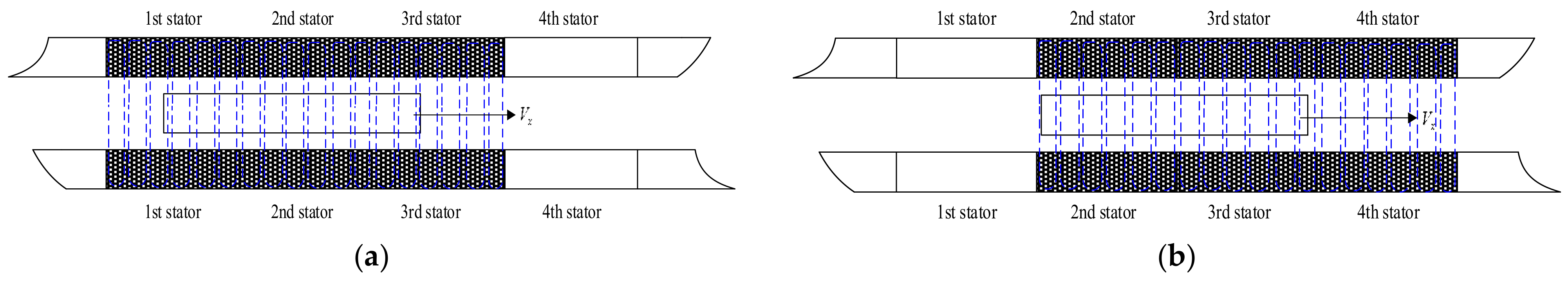
When a long-primary bilateral linear induction motor serves as a catapult drive, the stator, which is longer than the rotor, introduces challenges, for instance, limited voltage utilization. To mitigate these drawbacks, a segmented stator power supply is commonly adopted to enhance voltage use and improve the motor’s overall performance. The electrification schematic of the long primary bilateral linear induction motor is depicted in
Figure 1.
As shown in
Figure 1, the motor stator is significantly longer than the secondary rotor. The long motor stator section employs a sectional power supply approach. Four stator sections are shown in the figure, with three consecutive stator sections connected in series for operation, while the remaining stator sections are inactive. During specific time intervals, the first, second, and third stators of the linear motor are simultaneously powered, whereas the other stator segments remain unpowered, as depicted in
Figure 1a. When the rotor moves past the first stator, it is deactivated, and the fourth stator is started, as depicted in
Figure 1b. This ensures that three stators are powered simultaneously, maintaining the stator magnetic field and preserving the electromagnetic parameters of the effective rotor area.
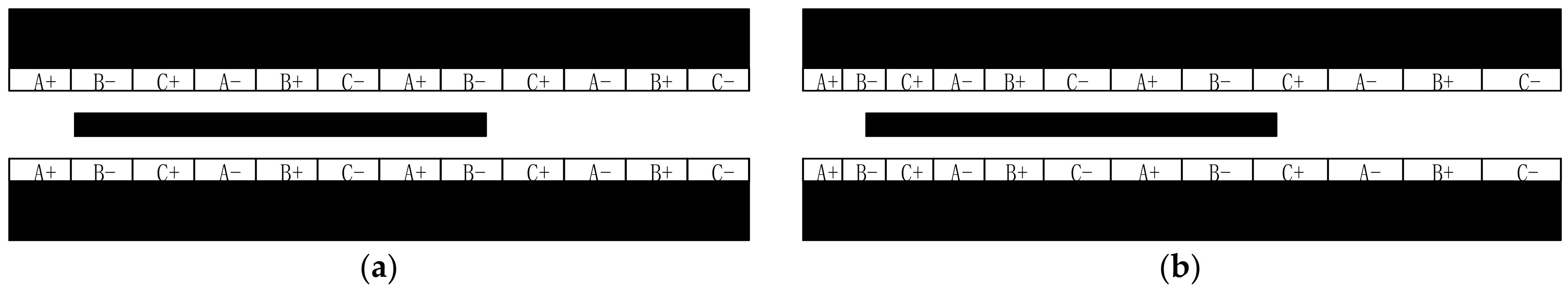
The equidistant motor featuring traditional windings is illustrated in
Figure 2a. Its slotless winding design minimizes volume and reduces the harmonic effects caused by the air gap magnetic field. To handle variable frequency acceleration during the acceleration phase, a large-capacity variable frequency drive is required, though this increases costs and lowers reliability.
The traditional double-sided linear induction motor with fixed pole spacing functions as an acceleration ejection system. The coil frequency must be adjusted to manage electromagnetic thrust. A closed-loop feedback system monitors speed and ejection displacement, ensuring the completion of the ejection task within the designated range. Despite its short duration, the ejection process is challenging to control. Moreover, higher speeds necessitate increased current frequency, placing demands on the inverter and increasing motor losses.
To address these challenges, we propose a variable pole length primary double-sided linear induction motor structure. In the early phase of design and manufacturing, CNC machine tools were used for machining. Depending on the required displacement, the manufacturing process allowed for varying pole distances.
Figure 2b presents the cross-sectional diagram of the primary winding structure for the variable pole distance bilateral linear induction motor.
Using a slotless winding structure, the motor enables the load to accelerate uniformly under constant voltage and frequency. By adopting a slotless winding structure, the motor facilitates uniform acceleration under a constant power supply of fixed voltage and frequency. This change in pole distance affects parameters such as the current magnitude, quality factor, and magnetic field strength, which, in turn, influences the motor’s magnetic field. By analyzing the magnetic field of the primary double-sided linear induction motor under variable torque conditions, the design parameters can be optimized to ensure the ejection acceleration task is completed within the specified time frame.
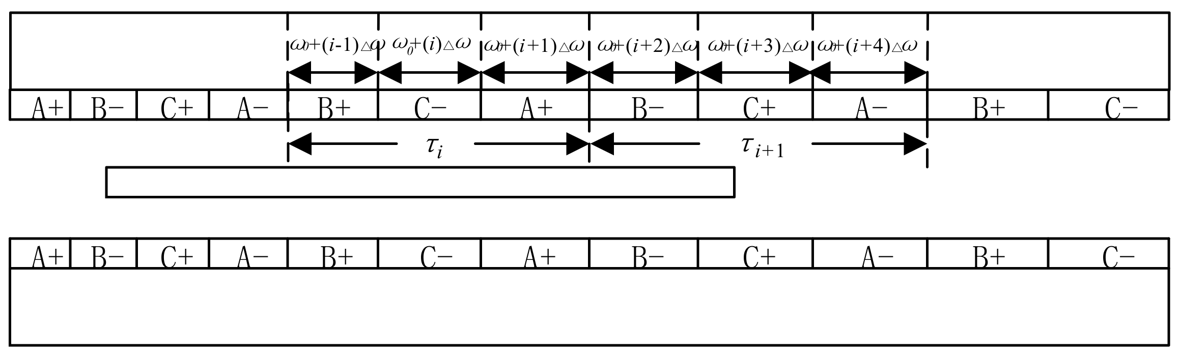
When analyzing a linear induction motor with continuous changes in pole distance, the variable pole distance mode is extended to the form of variable phase width, assuming that the phase bandwidth at the primary starting end of the linear induction motor is
. Along with the secondary direction of motion, the width of the phase band increases sequentially. In order to facilitate design and processing, the width of the phase band is incrementally increased to a constant value of
. The width of the i-th phase band of the variable pole distance linear induction motor is as follows:
Assuming the size of the i-th pole distance in any pair of poles is
, the size of the next pole distance adjacent to it is
, and the width of each phase band gradually increases by a constant value
. The widths of each phase band are shown in
Figure 3, and assuming that the motor speed before the i-th pole distance is
, it can be inferred from Newton’s laws of kinematics that the following is true:
For any pole distance, it corresponds to half a cycle, so the difference between Equations (2) and (3) can be obtained:
Therefore, Equation (1) can be organized as follows:
In the formula, is the acceleration value of the accelerated object; f is the power supply frequency.
3. Electromagnetic Ejection Requirements and Equivalent Circuit Analysis
Serving as the propulsion unit for the electromagnetic catapult system, the linear motor needs to provide sufficient thrust to complete the catapult mission of the carrier-based aircraft, and the entire catapult process is a constantly accelerating process. The acceleration track is usually 100 m, and the ejection mass is about 25 tons. The takeoff speed is about 100 m per second. Assuming that during the ejection process, the electromagnetic thrust is constant, and the engine power and external friction are ignored, the following can be determined from Newton’s second law and kinematic relationships:
In the formula, vt, t, and s, respectively, represent the end velocity of ejection, ejection time, and orbital length. It can be calculated that within a 100 m ejection trajectory, in order to achieve a takeoff speed of 100 m/s for the carrier-based aircraft, the linear motor needs to provide at least 1.25 MN of electromagnetic thrust, and the ejection time should be 2 s. After the launch of the carrier-based aircraft, the motor rotor needs to decelerate to zero within a short distance, usually stopping within 10 m. Therefore, the length and mass design of the rotor need to be within a reasonable range. If linear motor electromagnetic force braking is used to ensure that the electromagnetic force of 1.25 MN remains unchanged, the maximum mass of the moving element is designed to be 2500 Kg. If it exceeds this mass range, the moving element will not be able to brake within the specified length under the action of the electromagnetic force, and other external equipment will be needed to assist in braking.
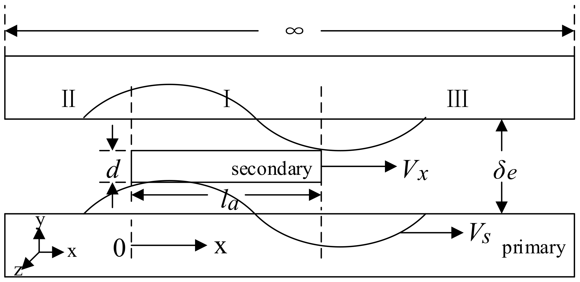
In the analysis of a long primary bilateral linear induction motor, the primary rotor is often treated as infinitely long and segmented into three regions based on the secondary rotor’s coverage: region I (
0 < x < la), region II (−
∞ < x < 0), and region III (
la < x < ∞), with
la representing the secondary length. The physical model is illustrated in
Figure 4.
Usually, Maxwell’s equations are typically employed to analyze the one-dimensional field problem of bilateral linear induction motors and to calculate the air gap magnetic field and other performance parameters. Taking the position at the secondary end as the origin, the current density of the primary synthetic traveling wave current layer is as follows:
here, the amplitude of the
traveling wave current layer is obtained.
In the formula,
s is the slip rate, and
Vs and
Vx are the primary current layer and secondary movement speed along the x-axis.
In the formula, f is the rated frequency of the motor; ω is the primary current angular frequency; and k = π/τ, τ represents the motor pole distance.
is the effective electromagnetic air gap of the motor; is the vacuum magnetic permeability; is the y-component of the air gap magnetic flux density in region I; and and are the line current densities of the primary and secondary, respectively.
By introducing vector magnetic potential A, the following can be derived from
and
:
Az1 represents the z-component of the vector magnetic potential
A in region I, while
Ez1 refers to the z-component of the electric field intensity in the same region.
is the surface conductivity of the secondary conductor. and it can be expressed as follows:
We solved the equation for Az1 in region I and, similarly, determined the magnetic potential in the other regions. Using the continuity of the magnetic flux density across the boundaries, we solved the undetermined coefficients, which allowed the calculation of physical quantities such as magnetic flux and electric field strength.
If the primary length is
lb and the secondary length is
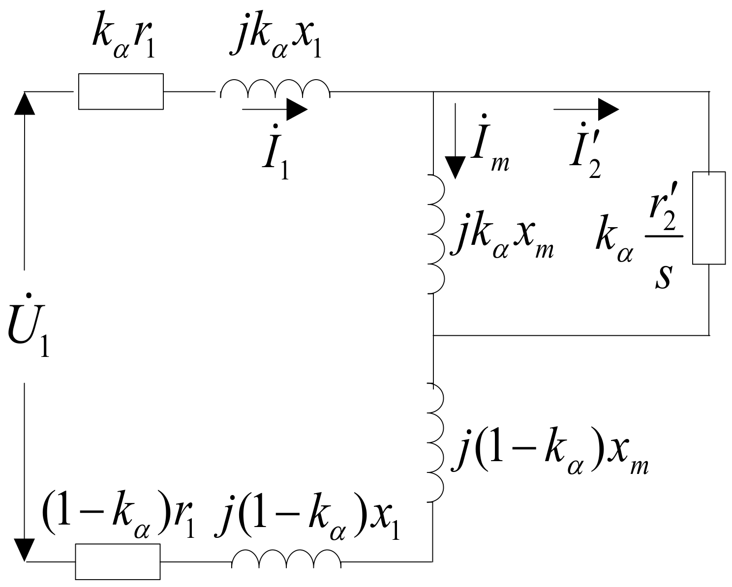
la in a long primary double-sided linear induction motor, the primary part covering the secondary part is defined as the effective part, and the uncovered secondary part is defined as the ineffective part. Therefore, the effective part’s impedance and ineffective part’s impedance can be used to describe the long primary double-sided linear induction motor, and its T-shaped equivalent circuit is shown in
Figure 5. To simplify the analysis, non-magnetic secondary leakage reactance and core loss are ignored.
Figure 5 shows the parameters of the motor, where
r1 and
x1 represent the resistance and leakage reactance of the primary winding, respectively, and
r′2 is the converted resistance from the secondary to the primary length. The excitation reactance is denoted as
xm. The ratio
kα = la/lb relates the secondary and primary lengths and divides the primary winding impedance into two components: the effective portion with impedance
kα(r1 + jx1) and the ineffective portion with impedance
(1
− kα)(r1 + jx1).Thus, the motor’s total series impedance
Z is as follows:
The electromagnetic thrust,
F, of a linear motor is given by the following:
In the formula above, m1 represents the number of phases in the primary winding, while I1 indicates the primary phase current and I2 indicates the phase current converted from the secondary to primary length.
Due to the infinite length of the primary length of the long primary bilateral linear induction motor for ejection, to simplify the analysis and neglect the influence of longitudinal end effects, the resistance and excitation reactance converted from the secondary to the primary length can be expressed as follows:
In this equation, d1 represents half of the width of the primary iron core; for kω, the primary winding coefficient, defined as the product of distribution and short distance coefficient, is kω = 1. The parameter ω1 refers to the number of turns per phase in the primary winding; the surface conductivity of the secondary conductor, σs, is expressed as σs = σd2, where σ is the material conductivity, the σ value is 3.53 × 10⁷ s/m, and d2 is half of the thickness of the secondary conductor. Here, p represents the number of motor poles, and μ0 is the vacuum magnetic permeability, with a value of 4π × 10−7 H/m. The effective electromagnetic air gap δe is given by δe = kμkδδ, where kμ and kδ are the saturation and air gap coefficient, respectively, with δ being the motor’s mechanical air gap. In addition, Vs = 2τf. Therefore, both r’2 and xm are related to the motor pole distance τ form a functional relationship.
4. The Influence of Motor Pole Distance on Motor Parameter Design
The primary winding resistance
r1 is determined by the average half-turn length of the winding, the resistivity of the wire, the number of series turns of the winding, and the cross-sectional area of the wire, which is not related to the pole distance value of the motor. The primary winding leakage reactance
x1 is only related to the rated current frequency, the number of series turns per phase, the number of motor pole pairs, and the number of slots per pole per phase, and is also independent of pole spacing. The simulation analysis shows the effects of changes in motor pole distance on the secondary phase resistance and magnetization reactance, as shown in
Figure 6, respectively.
It was found that the secondary phase resistance r’2 is inversely proportional to the motor pole distance. As the motor pole distance increases, its value decreases, while the magnetization reactance xm of each phase first decreases and then increases with the motor pole distance, achieving the minimum value near the rated pole distance value.
The magnetic circuit of a long primary bilateral linear induction motor relies on the air gap’s equivalent flux density, and the equivalent amplitude of the motor’s air gap magnetic field is the Bδ traveling wave magnetic field. The long primary double-sided motor has a pair of poles in the magnetic circuit. Due to the disconnection of the iron core at both ends, the magnetic flux only flows in one direction. After a quarter cycle, the magnetic flux will separate towards both sides. When calculating the magnetic circuit of a linear motor, the magnetic flux density should be calculated as twice the value obtained by the rotating motor magnetic flux algorithm.
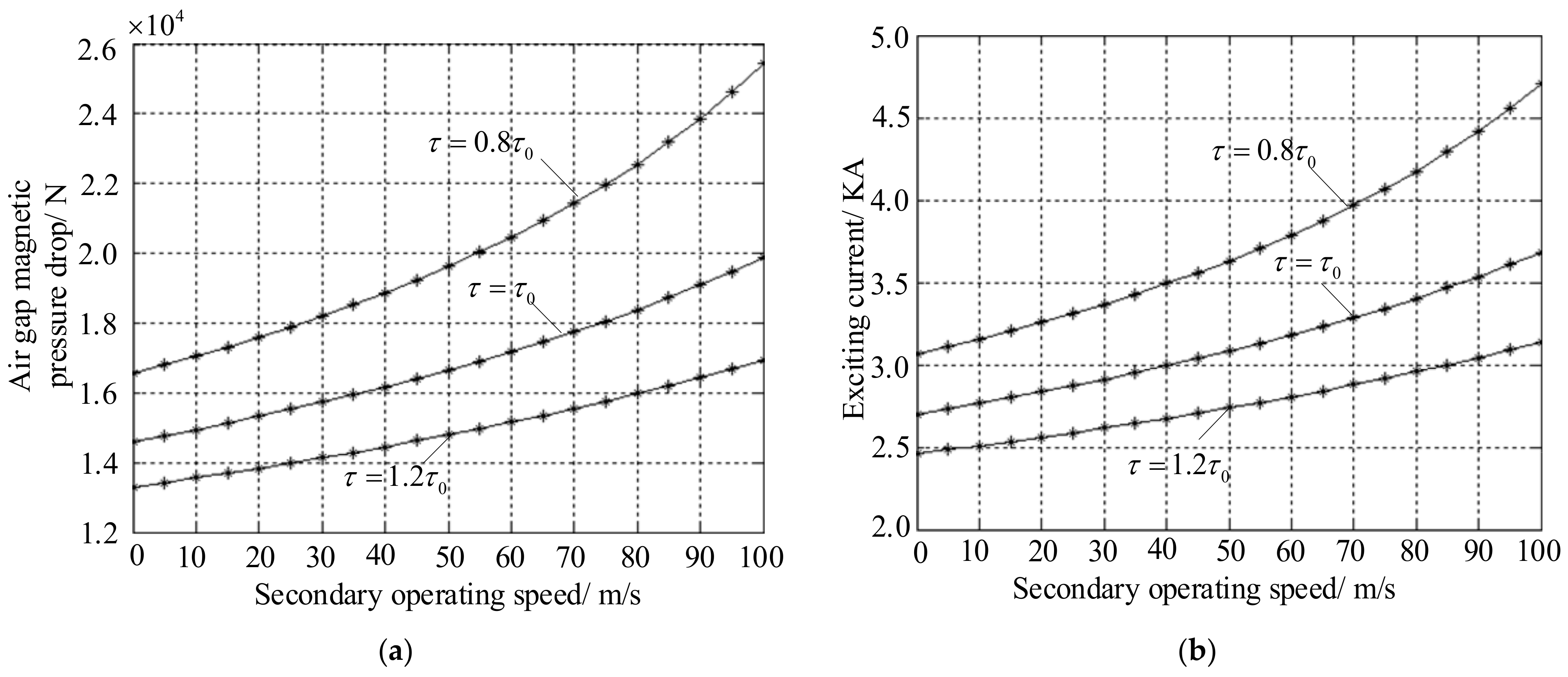
The formula for calculating the effect of pole distance variation on the air gap magnetic voltage drop and excitation current in a variable pole distance linear motor is used to analyze its impact, as shown in
Figure 7.
As the secondary speed of the linear motor increases, the air gap magnetic pressure drops Fδ, and the excitation current Im rises. However, for different pole distances, increasing the pole distance of the variable pole distance motor reduces the drop in the air gap magnetic pressure Fδ and excitation current Im. The effect of changes in magnetic circuit parameters becomes more significant with smaller pole distances.
The purpose of the magnetic circuit calculation is to adjust the magnetic density values across the motor and ensure the appropriate matching between them, as well as verify if the excitation current meets the design specifications.
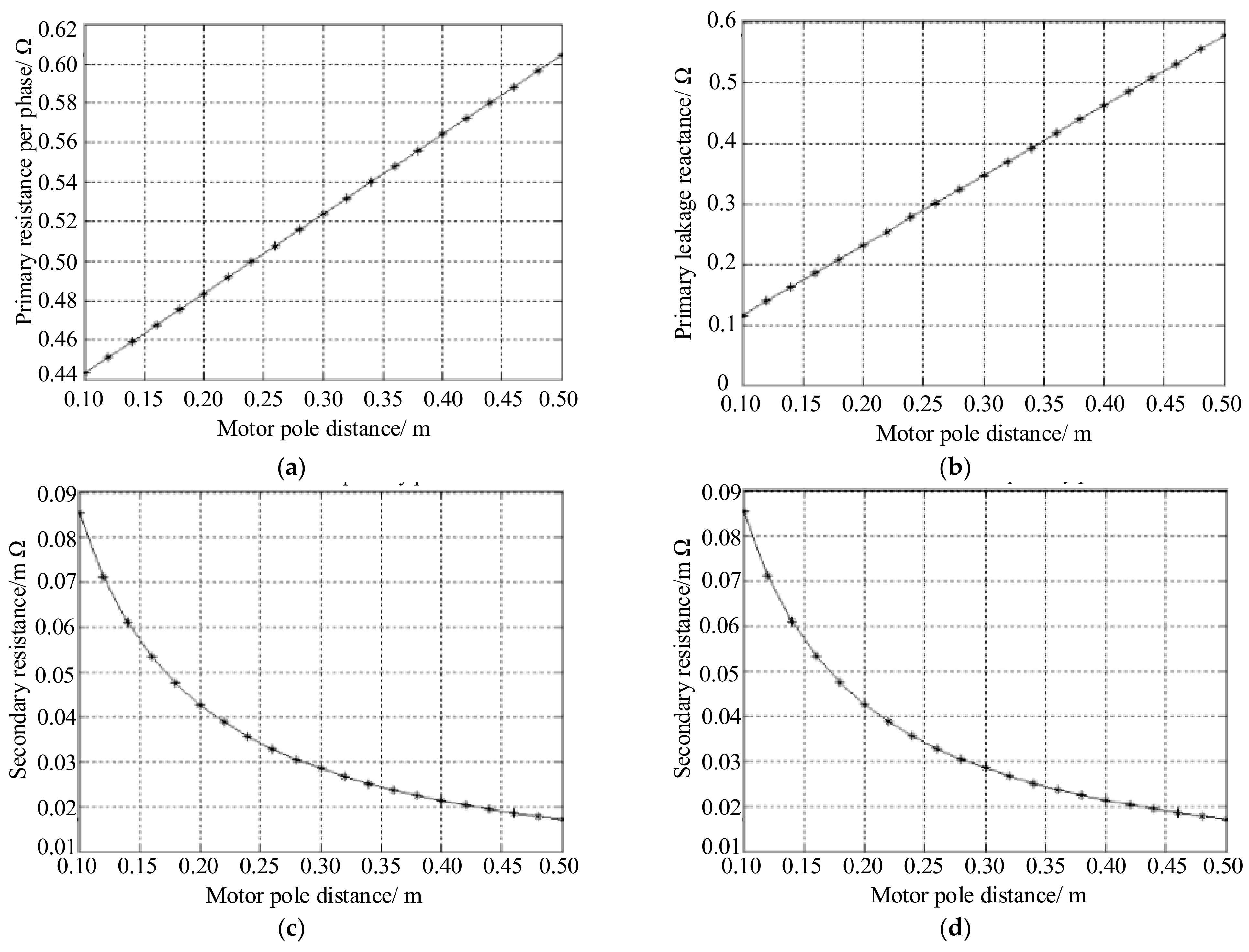
By calculating the parameters of a linear motor’s equivalent circuit, its operational performance can be analyzed during its design. The calculation of a variable pole pitch linear induction motor differs slightly from that of a rotating motor due to lateral and longitudinal end effects.
Figure 8 illustrates the impact of pole pitch changes on various parameters of the motor’s equivalent circuit.
When simulating the influence of pole distance variation on the equivalent circuit parameters of a variable pole distance linear induction motor, the primary phase resistance, primary leakage reactance, and motor pole distance are directly proportional, while the secondary resistance and secondary leakage reactance decrease with the increase in the motor pole distance. The size of the parameters of the equivalent circuit directly determines the calculation of motor losses; thus, the size of the motor pole distance directly affects the acceleration system losses.
In order to ensure that the linear motor provides sufficient electromagnetic force during the ejection process and to avoid the influence of a unilateral magnetic pulling force, the motor design adopts a double-sided structure. The stator adopts a modular structure with concentrated windings, which can reduce copper consumption and improve efficiency. The actuator adopts a sliding plate structure, which can reduce the ejection mass and also facilitate braking after ejection.
Table 1 provides the specific size design parameters of the bilateral linear induction motor, and other parameters can be queried through the linear induction motor design manual.
5. Kinematic Simulation Analysis of Electromagnetic Ejection
The design of the bilateral linear induction motor needs to meet the main technical specifications of the electromagnetic ejection system, which is to generate 1.25 MN of electromagnetic thrust. External interference and resistance effects are ignored in the preliminary design. In the design of a variable pole distance bilateral linear induction motor, the pole distance of the motor is the key to the design. During the ejection process, the pole distance can be continuously changed or segmented. A larger motor pole distance increases the leakage reactance and loss at the end of the primary winding, while a smaller motor pole distance will make motor processing more challenging. Typically, the pole distance ranges from 0.2 to 0.5 m, and the primary iron core width is 1.5 to 3.5 times the pole spacing, which can reduce weight and cost, as well as the length of the end winding. The design of secondary conductor plates can be calculated based on the shear stress they are subjected to, and the length of each side of the secondary transverse extension from the primary length should not be less than τ/π. The thickness of the secondary extension directly affects the traveling wave thrust. Reducing the thickness of the secondary extension is beneficial for reducing the excitation current and suppressing end effects, usually at 4–10 mm. The length of the air gap is an important parameter in the design of linear motors. Reducing the length of the air gap can increase the size of the traveling wave thrust and increase the efficiency of the motor. However, the size of the air gap is also limited by machining accuracy and assembly accuracy, usually ranging from 0.5 cm to 2 cm. The output frequency of the inverter is mainly determined by the ejection speed and the power electronic switch frequency according to f = vs/2τ. The power supply frequency of the inverter can be determined where vs is the synchronous speed of the motor. Due to the limitation of the switching frequency of the power device, the power supply frequency of the ejection system is usually 150–300 Hz.
It can be assumed that the traction force during the ejection process is only provided by the electromagnetic thrust generated by the linear motor, and the entire process is assumed to be in a constant acceleration process, ensuring that the electromagnetic thrust remains constant.
Using MATLAB 2012b to derive the electromagnetic thrust equation based on kinematic equations and the equivalent circuit method, a simulation model is established to verify and compare the superiority of variable pole pitch bilateral linear induction motor and traditional bilateral linear induction motor in shipborne aircraft ejection and to verify the influence of factors such as power frequency and secondary length on ejection.
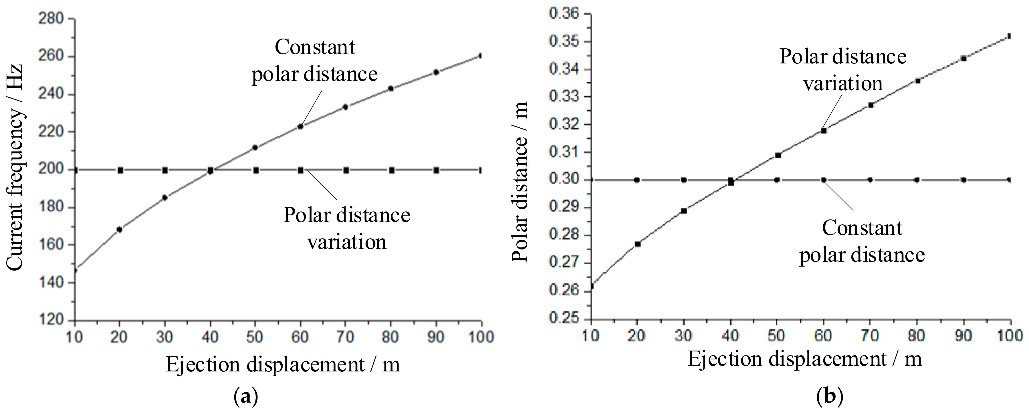
Figure 9, respectively, shows the required current frequency and motor pole distance relationship for different displacements and speeds, assuming that the electromagnetic thrust provided by the linear induction motor is constant at 1.25 MN, with fixed and variable pole distances, in order to meet the electromagnetic ejection needs of carrier-based aircraft.
When the pole distance is fixed at 0.30 m, the electromagnetic thrust is controlled by adjusting the current frequency, which increases continuously during the ejection. At a displacement of 10 m, i.e., a speed of 31.62 m/s, the current frequency increases to 146.5 Hz. When the speed increases to 100 m/s, i.e., at the takeoff position of the 100 m carrier aircraft, the current frequency increases to 260.5 Hz. The slip frequency during the entire ejection process remains constant at around 93.7 Hz, and the slip rate decreases sequentially from 0.64 to 0.36.
When using variable pole distance ejection, the control current frequency is fixed at 200 Hz. When designing the motor, different motor pole distances are used at different displacement positions to complete the shipborne aircraft ejection. Similarly, ensuring a constant 1.25 MN at a displacement of 10 m, i.e., at a speed of 31.62 m/s, the pole distance value is 0.262 m. At the takeoff position of a 100 m carrier-based aircraft and a speed of 100 m/s, the pole distance value is 0.352 m. Throughout the entire ejection process, the number of energized segments of the motor remained at three, while the slip frequency and slip rate continued to decrease.
Compared to the fixed pole range ejection, variable pole range ejection has a simpler control method. Due to the fact that the ejection process of the carrier-based aircraft only lasts for 2 s, controlling the rapid change in current undoubtedly increases the difficulty of the control system. However, using variable pole range ejection does not require changing the current frequency and only requires different pole distances at different displacement points during the initial design and manufacturing of the motor. The manufacturing process can be conveniently processed using CNC machine tools. Furthermore, as the speed of the ejection process increases, the required current frequency for traditional fixed pole distance bilateral linear induction motors continues to increase, inevitably limiting the inverter frequency. At high speeds, increasing the current frequency results in higher motor losses. However, variable pole distance bilateral linear induction motors can maintain a more optimal current frequency to minimize these losses.
The choice of ejection frequency is crucial in variable pole distance ejection, as it directly affects the corresponding pole distance for different ejection positions.
Figure 10 illustrates the relationship between ejection displacement, motor frequency, and pole distance for various pole settings.
Selecting a frequency that is too low can result in an increased motor pole distance, preventing the ejection task from being completed within the required distance. For instance, at a frequency of 150 Hz, the motor pole distances for the 20 m and 100 m ejection positions are 0.306 m and 0.417 m, respectively, both of which exceed the rated pole distance of 0.300 m. This makes it impossible to achieve the necessary pole distance segmentation within the specified 100 m range. On the other hand, selecting a frequency that is too high may be limited by the inverter’s switching frequency. For example, with a frequency of 250 Hz, the pole distance remains smaller than the rated 0.300 m throughout the entire ejection, allowing the task to be completed within a shorter distance. However, higher frequencies also increase motor losses and are constrained by the inverter’s capacity. Therefore, a frequency of 200 Hz is a more optimal choice.
In order to simulate and analyze the electromagnetic thrust output and its influencing factors, the motor is solved and analyzed using the transient solution method, and an ANSYS finite element model of a bilateral linear induction motor is developed, as shown in
Figure 11 and
Figure 12.
Through the magnetic field line and magnetic density distribution, it can be found that the magnetic density of the primary invalid part is greater than that of the effective part, and the magnetic density of the primary core at the secondary inlet is greater than that at the secondary outlet.
Table 2 shows the output relationship between the slip rate and electromagnetic thrust at a motor pole distance of 0.30 m and at a running speed of 30 m/s.
Figure 13 shows the output relationship between the slip rate and electromagnetic thrust at motor pole distances of 0.26 m, 0.28 m, and 0.30 m and at a running speed of 30 m/s. Among them, the solid line represents the theoretical calculation value, and the dashed line represents the finite element simulation value. The main reason for the error between the two is due to the infinite equivalent magnetic permeability and zero conductivity of the iron core during the theoretical calculation.
According to
Table 2 and
Figure 13, it can be seen that the two sets of data are almost identical, with only errors near the maximum electromagnetic force, which verifies the effectiveness of the theoretical calculation of the model.
6. Conclusions
Currently, the linear motors used for electromagnetic acceleration drives are all constant-pole-distance motors. By varying the current frequency in the primary winding, the electromagnetic thrust is adjusted, thereby controlling the acceleration rate. However, in the actual acceleration process, the time available is short, requiring the continuous detection of both position and speed, making the system more complex. To optimize the acceleration process, a design for a variable-pole-distance bilateral linear induction motor is proposed. The self-inductance and mutual inductance formulas for each winding of the variable-pole-pitch motor are derived, along with expressions for the electromagnetic thrust output and the maximum electromagnetic thrust value. The impact of pole pitch variation on motor performance is simulated and analyzed. Using finite element simulation software, the magnetic field lines and magnetic flux density distribution of the motor are analyzed to validate the theoretical calculations. The variable-pole-distance bilateral linear induction motor presents a new theoretical foundation for the optimal design of linear motors in carrier-based aircraft catapults, offering both significant theoretical importance and practical engineering value. Future research may focus on deriving optimal parameters based on acceleration index requirements through simulation verification in order to improve the motor’s power factor and efficiency.


