Abstract
This study presents a numerical investigation on the heat transfer and pressure drop characteristics of silver/water nanofluids (0.1–0.5 vol.%) flowing in tubes with four distinct expansion–contraction ratios (ECR = 1.25, 1.50, 1.75, and 2). Additionally, the impact of the distance between expansion and contraction (DEC) within the tubes was examined. The analysis was conducted under turbulent flow conditions and three-dimensional thermal convection in tubes subjected to a constant heat flux of 20 kW/m2, with the inlet Reynolds number maintained at approximately 20,000. The nanofluids were considered as single-phase and modeled in the Ansys Fluent 16 software through the finite volume method, and the equations were discretized through the second-order upwind scheme. The nanofluids demonstrated significant potential in enhancing thermal performance, particularly in tubes where the convective heat transfer coefficient was affected by abrupt expansion–contraction ratio (ECR). A maximum increase of up to 24.90% in the average convective heat transfer coefficient compared to the base fluid was observed. Exergy efficiency showed a tendency to increase by up to 29.97% with the use of nanofluids. The findings indicate that the convective heat transfer coefficient can both increase and decrease with the expansion–contraction ratio (ECR) of the tube, as can the pressure drop. Consequently, the application of this passive technique, incorporating silver/water nanofluids, holds promise for use in cooling systems, nuclear reactors, and other similar applications, provided they are meticulously designed.
1. Introduction
Abrupt expansion and contraction in tubes has numerous practical applications in equipment such as heat exchangers, combustors, ejector refrigeration systems, and nuclear reactors [1,2,3]. In many cases, the geometric modification of the tube is designed to enhance heat transfer, while, in other applications, the geometry variation is inherent to the system. The sudden change in the heat exchanger’s geometry leads to the formation of recirculation zones, which affect velocity, pressure, and temperature fields. In some applications, expansion and contraction positively impact thermal performance; however, in certain geometric configurations, this can lead to significant degradation in heat transfer [4].
To compensate for potential losses in thermal performance due to abrupt expansion and contraction in heat exchangers, some researchers have explored the use of nanofluids, which are colloidal suspensions containing nanometric solid particles. The dispersion of nanoparticles tends to enhance the thermal conductivity of conventional fluids (e.g., water, ethylene glycol, oil) due to the high thermal conductivity of particles like graphene (~5000 W/m∙K), carbon nanotubes (~3000 W/m∙K), silver (~406 W/m∙K), and others [5,6]. Figure 1 illustrates the number of search results for the term “nanofluid” in review articles, research articles, and book chapters. A steady increase in the number of publications over the past 20 years can be observed, likely driven by the promising results of nanofluids, particularly in heat exchanger applications.
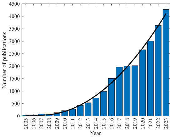
Figure 1.
Number of papers, according to year, using “nanofluid” as keyword on the ScienceDirect basis.
The thermal and hydraulic performance of Al2O3/water nanofluids with volumetric concentrations ranging from 0.5% to 2% was evaluated by [7] in a tube with three different expansion ratios (1.25, 1.67, and 2) under a constant wall heat flux (4000–16,000 W/m2). The study identified increases in the convective heat transfer coefficient with the rising expansion ratio (ER) of the tube. Additionally, it was observed in all cases that the local static pressure tends to decrease along the tube, especially at higher expansion ratios, before eventually increasing and converging at the tube exit. The size of the recirculation region is directly influenced by the expansion size, while the Reynolds number does not significantly affect it.
The authors of [8] conducted a numerical analysis on the heat transfer and hydraulic performance of Ag, Cu, CuO, and Al2O3/water nanofluids in an axisymmetric pipe with an abrupt expansion (ER = 1.53). The study identified an increase in heat transfer with the use of nanofluids and with the rising Reynolds number, showing a linear relationship depending on the type of nanoparticle used. Among the nanoparticles, Al2O3 exhibited the most significant increases in heat transfer. Additionally, two correlations were presented for the average Nusselt number, based on the Reynolds number, nanoparticle concentration, and variations in thermophysical properties.
In the experimental study on silver nanofluids (0.1–0.5 vol.%) and single-walled carbon nanotubes (0.03–0.2 vol.%) realized by [9] in a horizontal tube with a constant heat flux of 20 kW/m2 under turbulent flow conditions, with inlet temperatures of 20 °C and 25 °C, it was found that silver nanofluids improved thermal performance, whereas SWCNT nanofluids resulted in a reduction in performance. The pressure drop increased with the addition of nanoparticles, ranging from 5% for silver (Ag) to 8.7% for SWCNT. Silver nanofluids exhibited an enhancement in the convective heat transfer coefficient of up to 6.5% compared to the base fluid. Overall, silver nanofluids demonstrated improved thermo-hydraulic performance relative to the base fluid, while SWCNT nanofluids showed a degradation in performance.
The entropy generation of CuO/water nanofluids (2–4 vol.%) was evaluated numerically by [10] using Ansys Fluent software in a tube with an abrupt expansion–contraction ratio (ECR) and a spherical heat source located in the central region of the expansion. The study found that increasing the volumetric concentration of nanoparticles tends to increase entropy generation, while reducing the nanoparticle diameter (from 100 to 30 nm) tends to decrease entropy generation. Additionally, a reduction in entropy generation was observed with the increase in the size of the spherical heat source.
In the investigation of the effects of Cu/water nanofluids (0–6 vol.%) under the influence of an inclined magnetic field on heat transfer and the friction coefficient in a tube with an abrupt contraction realized by [11], it was identified that increasing the inclination of the magnetic field and the volumetric concentration of Cu nanoparticles tends to increase the friction coefficient. The highest Nusselt numbers were observed in the vertical magnetic field. Furthermore, an increase in nanoparticle concentration positively influenced heat transfer, with the highest Nusselt numbers recorded at a concentration of 6 vol.% and the lowest in the base fluid.
The heat transfer of a laminar flow of a Bingham viscoplastic fluid in vertical steps with various geometries was numerically analyzed by [12]. The study identified that the recirculation zones created by the steps are major contributors to thermal and hydraulic losses. Additionally, the size of these recirculation zones tends to decrease with reductions in the angle or changes in the shape of the steps. The maximum reduction in pressure drop, 58.83%, was observed with a rounded step facing backward. This geometry also yielded the highest Nusselt number.
In the numerical study about the influence of expansion angles (30°, 45°, 60°, and 90°) with Cu/water nanofluids (2 vol.% and 4 vol.%) in a microtube conducted by [13], it was identified that the addition of nanoparticles enhanced thermal performance, with the 45° abrupt expansion angle showing superior results compared to the other angles. The best performance was achieved with a nanofluid concentration of 4%, a Reynolds number of 100, and an expansion angle of 45°. Reducing the expansion angle from 90° to 45° resulted in up to a 14.57% increase in heat transfer. However, the 45° angle also led to the highest pressure drop among the cases analyzed.
The abrupt expansion, featuring an aspect ratio of 0.562 on intermittent two-phase flow patterns (air-water), was analyzed by [14]. The study found that the frequency of slugs decreases after the expansion region due to their breakup. Additionally, the void fraction decreases as the flow passes through the expansion region, causing a transition from Highly Aerated Slug to Less Aerated Slug. Knowing that the alteration of the streamlines can induce secondary flows, [15] carried out an experimental study of the water–oil flow in a horizontal serpentine channel. It was identified that, with the serpentine-shaped channel geometry, there is a better mixing of the fluids in relation to the straight tube, being a promising result for nanofluids, since this mixing can reduce possible sedimentation. In addition, [16] indicated that serpentine microchannels with oil–water for different curvatures present qualitatively different flow patterns.
The thermal-hydraulic behavior of water in a tube, with expansion and contraction under turbulent flow conditions (Re = 3640 to 4970) and a constant heat flux (9500 to 19,350 W/m2), was evaluated by [17] using Ansys Fluent software. The results were compared with experimental data from [18], showing a discrepancy of about 15%, with the largest deviations occurring at higher Reynolds numbers. The study identified a reduction in the thermal boundary layer due to the recirculation region, with the highest Nusselt number observed in the center of the expansion region, which decreased towards the contraction region.
In the numerical analysis performed by [19] about mono (TiO2) and hybrid (TiO2-SiO2) nanofluids in a conical diffuser with volumetric concentrations ranging from 0 to 1.5%, the influence of nanoparticle addition was compared with theoretical correlations and experimental data. Theoretical correlations showed limited impact on the Nusselt number with nanoparticle addition. TiO2 nanofluids exhibited decreased thermal performance compared to the base fluid, while hybrid nanofluids demonstrated both increases and decreases in heat transfer. The maximum increase for TiO2-SiO2 nanofluids was 5%, and the maximum reduction was 9.7%. For TiO2 nanofluids, the reduction was approximately 19% at the highest nanoparticle concentration.
The thermo-hydraulic performance of Al2O3/water nanofluids (1–4 vol.%) in a channel with contraction and ribs under turbulent conditions (Re = 10,000 to 40,000) was numerically analyzed by [4]. The study found that the pressure coefficient decreased with the tube diameter contraction, with a more significant reduction at higher Reynolds numbers. For a Reynolds number of 40,000, the coefficient reached −2500 Pa in the contraction region, where the flow direction reverses. The Nusselt number increased by up to 3.07% with changes in nanoparticle volumetric concentration from 1% to 4%.
Few studies have analyzed the influence of the expansion–contraction ratio (ECR) within the same pipe. Furthermore, the distance between the start and end of the expansion–contraction (DEC) also significantly impacts heat transfer and pressure drop, yet few studies have examined these effects and optimized the heat transfer process. Addressing this gap and considering the promising results of nanofluids in enhancing heat transfer, this work aims to perform a numerical analysis of turbulent flow using silver/water nanofluids (0.1 vol.%–0.5 vol.%) in both a straight tube and tubes with varying ECR (1.25, 1.50, 1.75, and 2) and DEC regions, under a constant wall heat flux of 20 kW/m2.
2. The Problem Statement
As illustrated in Figure 2 and Figure 3, the geometric model consists of a three-dimensional, circular, and straight tube with an inlet hydraulic diameter of 6.35 mm and a length of 600 mm. Additionally, the model includes a tube with an expansion–contraction ratio (ECR) in the central region, where the distance between the contraction and expansion (DEC) is 50 mm, 100 mm, or 150 mm, and the ECR values are 1.25, 1.50, 1.75, and 2. The ECR is defined as the ratio between the expansion diameter and the inlet diameter.
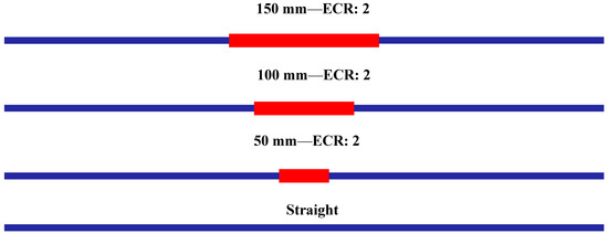
Figure 2.
Distance between expansion–contraction (DEC) in the tube for ECR = 2.
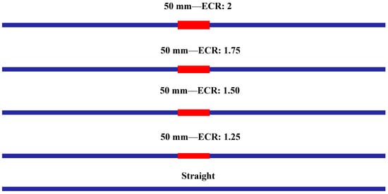
Figure 3.
Expansion–contraction ratio (ECR) of the tube for the distance of 50 mm.
The flow is assumed to be in a stationary, turbulent regime with a Reynolds number of 20,011, and is hydrodynamically developed at the tube inlet with a constant temperature of 20 °C. Wall regions are subject to a non-slip condition and a constant heat flux of 20 kW/m2. At the tube exit, the relative pressure is set to zero. The geometric configurations and input conditions are consistent with those used by [9], which were experimentally analyzed only for the straight tube. The boundary conditions used in this work are similar to those adopted by [20], in which in the tube outlet region there is a configuration of a zero axial gradient for the variables analyzed and a zero value for the static pressure.
3. Numerical Procedure
3.1. Governing Equations
In the numerical simulations, both water and silver/water nanofluids were treated as Newtonian, incompressible, single-phase fluids. These assumptions, consistent with those used by [21], yield satisfactory results given the low volumetric concentration of nanoparticles (0.1–0.5%). The conservation equations for continuity, momentum, and energy in turbulent flow are modeled according to Equations (1)–(3). These equations are solved using Ansys Fluent software [22,23].
where, is the density, represents the velocity, is the coordinate, refers to the pressure, is the dynamic viscosity, is the Kronecker delta, refers to the thermal conductivity, is the specific heat, é the Prandtl number and is the temperature. . The term refers to the deviatoric stress tensor, which is calculated through Equation (4).
The SST model was used as a turbulence model, whose transport equations are described in (5) and (6). The choice of this model is due to its advantages over other models available in the Ansys Fluent software for abrupt expansion–contraction problems. The SST model is not susceptible to variations in boundary conditions [24]. Furthermore, this model tends to provide more accurate results for flow separation (as in the problem analyzed in this work) when compared to other RANS models [23,25].
In the previous expression is defined through Equation (7) where represents the production of turbulent kinetic energy arising from the average velocity gradients. refers to the generation of . and .
The represents the kinematic turbulent viscosity and is a constant of the SST model. is given through Equation (8).
where , , and . The turbulent Prandtl numbers of and are defined through Equations (9) and (10), respectively.
The turbulent viscosity is calculated using Equation (11).
The coefficient represents the damping of turbulent viscosity according to Equation (12).
where , , and . For high Reynolds numbers, . The term is given through Equation (13).
where , represents the distance to the region solid. refers to the positive part of the cross-diffusion term, according to Equation (14).
where e represent the dissipation of and , respectively. and are constants. . represents the cross-diffusion term. and are possible source terms [22,26]. The constants of the SST model are highlighted in Table 1.

Table 1.
Model constants SST .
For the discretization of the diffusive and convective terms, the second-order upwind scheme was used, while for the pressure–velocity coupling the Semi-Implicit Method for Pressure Linked Equations (SIMPLE) scheme was used [23]. As a stopping criterion, it was defined that the residuals of the equations were less than 10−6, except for the energy equation which was set to 10−9, similar to found in [17].
3.2. Software Verification and Computational Model Validation
3.2.1. Software Verification
As performed by [4], the Ansys Fluent software was initially validated. A numerical simulation of water flow and heat transfer in a straight tube, with identical geometry and input conditions as those used in the experimental work by [9], was conducted. The results for the convective heat transfer coefficient and pressure drop were compared with the experimental data. As shown in Table 2, the numerical results exhibit satisfactory agreement with the experimental data, demonstrating that Ansys Fluent is robust and reliable for solving this type of problem.
Table 2.
Software verification with experimental data from [9].
3.2.2. Mesh Independence and Computational Model Validation
Increasing the refinement of the computational mesh generally enhances the accuracy of the results. However, a finer mesh also raises the computational cost. Therefore, it is essential to balance accuracy and computational cost through a mesh independence study. For this study, three structured meshes with different numbers of cells (130,496, 187,764, and 245,032) were used for numerical simulations under the same input and boundary conditions (as described in Section 2).
Mesh convergence was performed with the Nusselt number, as shown in Figure 4. It can be observed that the increase in the number of elements between meshes 2 and 3 does not result in a significant difference, resulting only in an increase in computational cost. For mesh 1, the numerical results show a result higher than 5% in relation to the correlation, while meshes 2 and 3 have a difference of about 1%. To accurately capture the velocity, pressure, and temperature gradients, 15 layers of prismatic elements were created near the wall [25]. Additionally, the Grid Convergence Index (GCI) [27] was assessed. The GCI (0.01%, 4.99%, 5.02%) value was found to be less than 5%, indicating that the results are within the asymptotic range. Consequently, mesh 2 was selected for this work due to its satisfactory results [28,29].
The computational model (Figure 2 and Figure 3) was validated for the base fluid in a tube without an expansion–contraction ratio (ECR) using theoretical models as outlined in Table 3. This validation procedure is based on works by [22,25,30]. It was found that the numerical simulations show satisfactory agreement with correlations for the average Nusselt number [31,32,33], friction factor [31,34], and the temperature at the tube exit (calculated using the heat transfer rate equation ). Similar to [22], the correlation from [33] exhibited a greater deviation in the Nusselt number compared to the correlation from [31], despite having the same Reynolds number and similar Prandtl number. The differences presented in Table 3 refer to the value found in the present work and the correlations presented.
Table 3.
Validation of the thermal and hydraulic performance of the computational model.
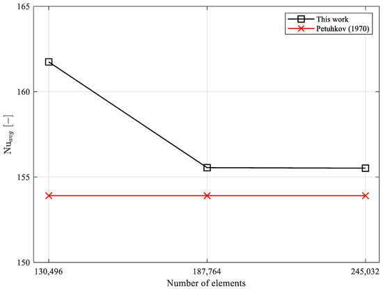
Figure 4.
Study of mesh independence and comparison with Petukhov (1970) [31] correlation.
4. Thermophysical Properties
The thermophysical properties of the coolants are consistent with those used by [9], as detailed in Table 4 for 20 °C. Thermal conductivity (λ) and dynamic viscosity (μ) were experimentally determined using the transient hot wire method with a Hukseflux TP-08 probe and a Brookfield LDDV-IIIU cone-plate rheometer, respectively. According to [9], thermal conductivity increased by approximately 8%, 18%, and 38% with nanoparticle volumetric concentrations of 0.1%, 0.3%, and 0.5%, respectively. Dynamic viscosity showed increases of about 2.4%, 4.5%, and 6.6% for nanofluids with the same volumetric concentrations. During the validation of the computational model, it was observed that the temperature variation of the flow was minimal. Therefore, the thermophysical properties of the fluids were considered temperature-independent, as similarly adopted by [25].
Table 4.
Thermophysical properties. Source: [9].
Considering the nanofluids as a homogeneous mixture, the specific heat (Cp) and density (ρ) were calculated using the correlations from [35] and [36], as outlined in Equations (15) and (16), respectively. The silver nanoparticles used are spherical and in powder form, sourced from Nanostructures & Amorphous Material Inc. (Katy, TX, USA). The geometric configuration and properties of these nanoparticles are detailed in the work of [9].
where refers to the concentration of nanoparticles. The subscripts np and bf refer to the nanoparticle and base fluid, respectively. According to [9], the correlations used present satisfactory agreement with experimental data available in the literature.
5. Data Reduction
To obtain and compare the data, the following equations were used to calculate the thermal and hydraulic performance of the base fluid and nanofluids based on the velocity, pressure, and temperature fields from the numerical simulations. The equations employed in this study are consistent with those used by [9]. The local and average convective heat transfer coefficients, average Nusselt number , friction factor , thermal and frictional entropy generations, exergy efficiency and entropy generation number are calculated using the Equations (17)–(24).
where refers to the heat, is the temperature at the wall, represents the temperature of the fluid, is the hydraulic diameter at the inlet of the tube, is the conductivity of the coolant, is the pressure drop, refers to the length of the tube, represents the density of the cooling fluid, is the flow velocity, represents the heat transfer rate, and are the inlet and outlet temperature, is the ambient temperature and is the surface temperature.
6. Results and Discussions
This work presents a three-dimensional numerical simulation of the flow and heat transfer of silver/water nanofluids across thirteen different tube configurations, both with and without expansion–contraction, under turbulent conditions. This section discusses the effects of the expansion–contraction ratio (ECR), the distance between expansion and contraction (DEC), and the volumetric concentration of silver nanoparticles on the local and average convective heat transfer coefficients, pressure drop, and overall thermal-hydraulic performance.
6.1. Local Convective Heat Transfer Coefficient
Figure 5 illustrates the local convective heat transfer coefficient for both the base fluid and silver/water nanofluids with volumetric concentrations ranging from 0.1% to 0.5%. The effects of nanoparticle concentration and the distance between expansion and contraction (DEC) are shown for a tube with an expansion–contraction ratio (ECR) of 2.
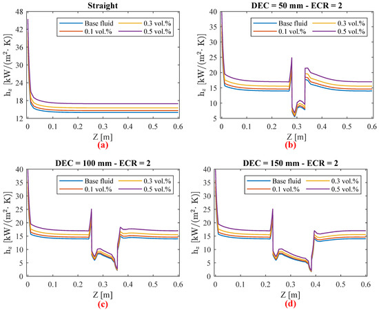
Figure 5.
Local convective heat transfer coefficient for constant ECR = 2 to the (a) straight tube, (b) DEC = 50 mm, (c) DEC = 100 mm, and (d) DEC = 150 mm.
As noted by [8], there is a sharp increase in thermal performance near the expansion region, which then decreases compared to the straight tube (ECR = 1). This effect is further pronounced with an increasing distance between expansion and contraction (DEC). Additionally, in all analyzed cases, an increase in the local convective heat transfer coefficient is observed in the expansion region. However, this increase is followed by a decrease until the tube contracts, a behavior also reported by [37]. This phenomenon can be attributed to the abrupt reduction in flow velocity and the appearance of recirculation zones within the expansion region, which tends to decelerate the flow more significantly with a larger DEC, as shown in Figure 6 [4,38]. In addition, part of the fluid pressure energy is not converted into kinetic energy in the contraction region due to the recirculation zone and the abrupt change in the geometry pipe. In the central part of the tube, flow deceleration can reach up to 75% compared to the straight tube (ECR = 1) at the same position.
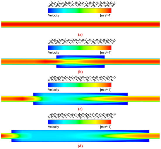
Figure 6.
Velocity contour for constant ECR = 2 to the (a) straight tube, (b) DEC = 50 mm, (c) DEC = 100 mm, and (d) DEC = 150 mm.
Among the cases analyzed in this study, nanofluids consistently demonstrate superior thermal performance compared to the base fluid, irrespective of the DEC and ECR. However, there were no significant changes observed in the points of flow detachment and reattachment with the addition of nanoparticles, consistent with the findings of [19]. The highest value of the convective heat transfer coefficient is observed in the tube inlet’s thermal developing region, due to the greater temperature difference between the wall and the fluid. While there are improvements in the local convective heat transfer coefficient peaks, these gains are not sufficient to offset the reductions observed in the expansion region. As noted by [39,40], a new peak in heat transfer occurs at the point of flow reattachment, with this peak being higher at increased nanoparticle concentrations. This suggests that the convective heat transfer coefficient is strongly influenced by the thermophysical properties of the nanofluids.
Among the analyzed cases, a smaller distance between expansion and contraction (DEC) generally yields better results due to a smaller reduction in thermal performance. This finding is corroborated by the average convective heat transfer coefficient values, as shown in Figure 7. In the region close to the tube contraction with DEC = 50 mm, the local convective coefficient values are higher than those in the region immediately before the expansion. This behavior can be attributed to the increased velocity in this area, particularly in the central flow, as illustrated by the velocity contours in Figure 6. However, when the DEC is increased to 100 mm and 150 mm, the thermal performance after contraction shows a decline.
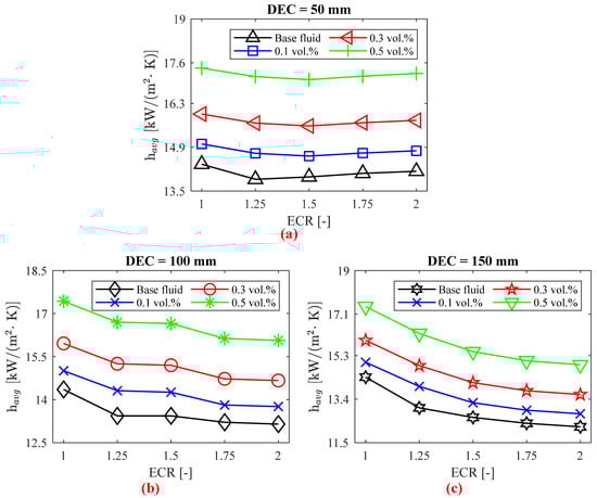
Figure 7.
as a function of tube expansion–contraction ratio (ECR) to the (a) DEC = 50 mm, (b) DEC = 100 mm, and (c) DEC = 150 mm.
6.2. Average Convective Heat Transfer Coefficient
As illustrated in Figure 7, the abrupt geometric variation of the tube and the distance between expansion and contraction (DEC) significantly influence the heat transfer process. It was observed that, as the DEC increases, the reduction in the convective heat transfer coefficient becomes more pronounced compared to a straight tube (ECR = 1). For a DEC of 50 mm, there is an initial reduction (up to 3.36%) in the average convective heat transfer coefficient, , with increasing ECR. However, tends to increase again despite further increases in ECR. For instance, with the base fluid, there was a 1.85% increase in when the ECR varied from 1.25 to 2. The application of silver nanofluids resulted in increases in the convective heat transfer coefficient of up to 6%, 12.95%, and 23.66% for volumetric concentrations of 0.1%, 0.3%, and 0.5%, respectively. The largest increases were observed at an ECR of 1.25, where the base fluid experienced a greater decline in thermal performance compared to the straight tube (ECR = 1).
In the case of a distance between expansion and contraction (DEC) of 100 mm, the reduction in the convective heat transfer coefficient becomes more pronounced compared to the DEC of 50 mm. For this DEC, variations in ECR negatively impacted the heat transfer process relative to the straight tube (ECR = 1) in all scenarios. A reduction of up to 8.41% was observed with the base fluid for ECR = 2. Notably, for ECR values between 1.25 and 1.5, the average convective heat transfer coefficient did not show significant variation. In comparison to the base fluid, the nanofluids achieved thermal performance increases of up to 6.55%, 13.53%, and 24.28% for volumetric concentrations of 0.1%, 0.3%, and 0.5%, respectively. As with the DEC of 50 mm, the greatest improvement in the convective heat transfer coefficient due to the nanofluids was observed for an ECR of 1.25.
With the increase in DEC from 100 mm to 150 mm, the negative effects on thermal performance due to the increase in ECR exhibit an almost exponential behavior within the studied range. The largest reduction observed was 15.07%, occurring with the base fluid and an ECR of 2, as well as a DEC of 100 mm. However, the use of nanofluids improved the convective heat transfer coefficient by up to 7.17%, 14.16%, and 24.90% for volumetric concentrations of 0.1%, 0.3%, and 0.5%, respectively. The greatest improvement in thermal performance was noted for an ECR of 1.25, consistent with the findings for DEC values of 50 mm and 100 mm.
As shown in Figure 8, silver/water nanofluids consistently mitigated the adverse effects of varying the ECR of the tube. For instance, with a nanofluid concentration of 0.5%, the reduction in the convective heat transfer coefficient was diminished from 3.36% to 1.55% for a DEC of 50 mm. For a DEC of 100 mm, the decrease was reduced from 6.42% to 4.19%, and for a DEC of 150 mm, the reduction in was reduced from 9.32% to 6.70% compared to the base fluid. In summary, nanofluids demonstrate superior thermal performance compared to water. However, as DEC increases, a higher nanoparticle concentration is needed to offset the reduction in the convective heat transfer coefficient.
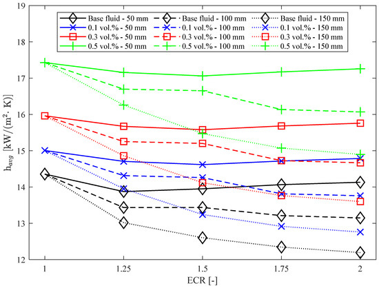
Figure 8.
Average convective heat transfer coefficient as a function of DEC, ECR, and nanoparticle concentration.
For comparison purposes, at DEC = 50 mm with the lowest concentration nanofluid (0.1 vol.%), the convective heat transfer coefficient exceeds that of the base fluid across all ECR values. This indicates that the negative impact of ECR on heat transfer in a heat exchanger can be mitigated by adding nanoparticles to the base fluid. As previously mentioned, and illustrated in Figure 8, increasing DEC exacerbates the negative influence on thermal performance. For DEC = 100 mm, the nanofluid with 0.1 vol.% silver nanoparticles does not outperform the base fluid at any ECR value, indicating that a nanofluid concentration of at least 0.3% is necessary for improved performance. For DEC = 150 mm, a nanofluid concentration of 0.5 vol.% is required to ensure that does not fall below the base fluid values, even with varying ECR.
Thus, silver/water nanofluids demonstrate superior thermal performance compared to the base fluid, presenting a promising solution for applications involving tube expansion–contraction, which is common in various systems such as oil refineries and heat exchangers [1,2,4].
6.3. Pressure Drop
As illustrated in Figure 9, both the expansion–contraction ratio (ECR) and the distance between expansion and contraction (DEC) significantly influence the pressure drop (Δp) in circular and horizontal tubes used in heat exchangers. Although the addition of nanoparticles enhances thermal performance, it can also increase the pressure drop due to the higher dynamic viscosity of the coolant [38]. It was observed that increasing DEC generally reduces the pressure drop for both the base fluid and nanofluids, while ECR can have mixed effects.
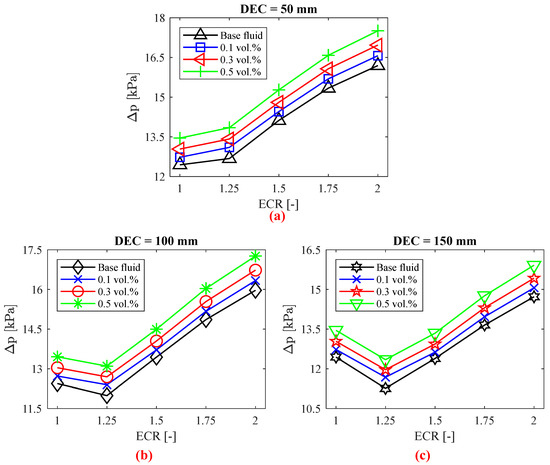
Figure 9.
as a function of tube expansion–contraction ratio (ECR) to the (a) DEC = 50 mm, (b) DEC = 100 mm, and (c) DEC = 150 mm.
For DEC = 50 mm, an increase in pressure drop of up to 30.17% was identified for the base fluid with ECR = 2 compared to a straight tube (ECR = 1) with the same fluid. Additionally, increasing ECR negatively impacted the pressure drop, with all cases showing higher values compared to the straight tube. The introduction of nanofluids led to pressure drops increasing by up to 3.34%, 5.84%, and 9.21% for volumetric concentrations of 0.1%, 0.3%, and 0.5%, respectively. These increases in pressure drop due to the addition of silver nanoparticles align with the results found by [9], with the greatest increases occurring at ECR = 1.25, similar to the trend observed for the convective heat transfer coefficient.
At DEC = 100 mm, there was an initial reduction in pressure drop of up to 3.64% for ECR = 1.25. However, increasing ECR between 1.5 and 2 led to a rise in pressure drop by up to 28.35% compared to the straight tube (ECR = 1). The application of silver/water nanofluids resulted in pressure drops increasing by up to 3.40%, 5.90%, and 9.27% for volumetric concentrations of 0.1%, 0.3%, and 0.5%, respectively. As with DEC = 50 mm, the greatest pressure drop increase due to nanoparticles occurred at ECR = 1.25, where the pressure drop was influenced significantly by the geometric variation.
Increasing DEC from 100 mm to 150 mm notably reduced the pressure drop, particularly for ECR = 1.25, where the reduction was approximately 9.5% compared to the straight tube with the same fluid. ECR = 1.5 also reduced the pressure drop compared to the tube without expansion–contraction, although the effect was not significant. For ECR values of 1.75 and higher, the pressure drop increased again, with a maximum rise of 18.34% compared to the straight tube (ECR = 1). As expected, all cases involving nanofluids showed an increase in pressure drop, with the highest increase being 18.34% for the nanofluid with a volumetric concentration of 0.5%.
As illustrated in Figure 10, variations in the expansion–contraction ratio (ECR) of the tube have minimal impact on the pressure drop relative to the concentration of nanoparticles, which contrasts with the findings of [13]. For instance, at DEC = 50 mm and ECR = 2, the pressure drop increases compared to the straight tube are 30.17%, 30.17%, 30.14%, and 30.15% for the base fluid and nanofluids with volumetric concentrations of 0.1%, 0.3%, and 0.5%, respectively. The increase in pressure drop with higher ECR can be attributed to the Coandă effect, where, at higher ECR values, the flow streamlines become less regular along the tube wall region [13].
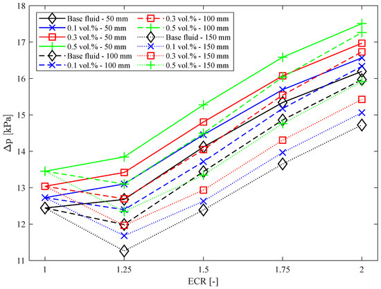
Figure 10.
Pressure drop as a function of DEC, ECR, and nanoparticle concentration.
The influence of expansion–contraction ratio (ECR) and the distance between the expansion and contraction distance on the pressure drop can be explained by variations in the velocity profiles and turbulence generated in the expansion and contraction regions, as illustrated in Figure 6. The increase in pressure drop with increasing ECR occurs due to the increase in the contact area with the fluid, resulting in a greater pressure drop [38]. In addition, with the appearance of recirculation zones, there is a greater friction loss, especially in cases with higher ECR, as was observed in the pressure drop in Figure 9.
6.4. Entropy Generation
Figure 11 illustrates the thermal and frictional entropy generation, calculated using Equations (22) and (23) [41,42,43]. A reduction in of up to 6.69%, 12.40%, and 19.93% was observed with the use of silver/water nanofluids with volumetric concentrations of 0.1%, 0.3%, and 0.5%, respectively, for the tube with ECR = 1.25 and DEC = 150 mm. This reduction is attributed to the smaller temperature difference between the wall and the fluid in the nanofluids compared to the base fluid, resulting in lower thermal entropy generation, as also noted by [42,44]. Furthermore, while the reduction in thermal entropy generation due to nanofluids remains relatively constant with increasing DEC, DEC increases tend to raise thermal entropy generation by up to 15.85%. For the analyzed cases, there is an increase in thermal entropy generation with higher expansion–contraction ratios (ECR) relative to the straight tube (ECR = 1), except for DEC = 50 mm, where initially increases up to ECR = 1.25, and then decreases for both the base fluid and nanofluids.
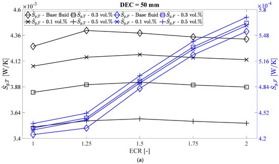
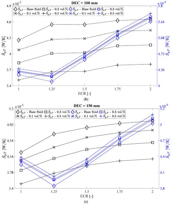
Figure 11.
Thermal and frictional entropy generation versus ECR to the (a) DEC = 50 mm, (b) DEC = 100 mm, and (c) DEC = 150 mm.
In Figure 11, an increase in the frictional entropy generation of up to 2.76%, 3.30%, and 4.65% was observed with nanoparticle volumetric concentrations of 0.1%, 0.3%, and 0.5%, respectively, compared to the base fluid, for a tube with an ECR of 1.25 and a DEC of 150 mm. This behavior can be attributed to the increase in velocity gradient, the rise in dynamic viscosity (due to the addition of silver nanoparticles), and the decrease in fluid temperature, all of which contribute to higher frictional entropy generation [45,46]. However, for DEC values of 100 mm and 150 mm and ECR values of 1.25 and 1.5, there is a reduction in frictional entropy generation compared to the straight tube (ECR = 1). The behavior of the straight tube aligns with experimental results obtained by [47].
6.5. Total Entropy Generation
Figure 12 illustrates the total entropy generation for both the base fluid and the silver/water nanofluids. Total entropy is the sum of frictional and thermal entropy . As noted previously, thermal entropy generation decreases with the addition of nanoparticles, while frictional entropy generation tends to increase. However, the decrease in thermal entropy generation is generally more significant than the increase in frictional entropy generation, resulting in an overall reduction in total entropy generation, as reported by [46]. Specifically, reductions in total entropy generation compared to the base fluid were observed to be up to 5.99%, 11.21%, and 18.08% for silver/water nanofluids with volumetric concentrations of 0.1%, 0.3%, and 0.5 vol.%, respectively.
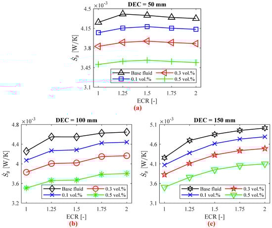
Figure 12.
Total entropy generation as a function of tube expansion–contraction ratio (ECR) to the (a) DEC = 50 mm, (b) DEC = 100 mm, and (c) DEC = 150 mm.
Figure 12 also shows that changes in DEC have a minimal impact on total entropy generation. This behavior can be attributed to the balance between the reduction in thermal entropy generation and the increase in frictional entropy generation, as illustrated in the figure.
6.6. Exergy Efficiency
Figure 13 illustrates the exergy efficiency for both the base fluid and silver/water nanofluids across different DEC and ECR values. To achieve optimal exergy performance, a lower entropy generation or higher is desired. Exergy efficiency is defined as the ratio between useful exergy output and the exergy of the heat supplied, as given by Equation (24) [42,44]. It was found that exergy efficiency increases by up to 8.86%, 17.98%, and 29.97% with silver nanoparticle volumetric concentrations of 0.1%, 0.3%, and 0.5%, respectively. This indicates that exergy losses are reduced compared to the base fluid, aligning with the findings of [42].
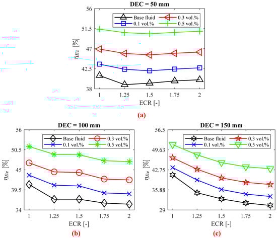
Figure 13.
as a function of tube expansion–contraction ratio (ECR) to the (a) DEC = 50 mm, (b) DEC = 100 mm, and (c) DEC = 150 mm.
Figure 13 also reveals a decrease in exergy efficiency with increasing DEC compared to a DEC of 50 mm, with a reduction of up to 21.26%. This trend mirrors the behavior of the convective heat transfer coefficient, due to the dependence of , as described in Equation (22), on thermal entropy generation. Table 5 provides a comparison of the exergy efficiency of the fluids analyzed in this study with similar works available in the literature under comparable conditions.
Table 5.
Comparison of the exergy efficiency of the straight tube in the present study with previous works.
In the work by [48], ZrO2/water nanofluids (0–1 vol.%) were used in a straight horizontal tube, achieving an exergy efficiency of 38% for the base fluid at a Reynolds number of approximately 19,700. Similarly, [49] evaluated diamond-Fe3O4/water hybrid nanofluids and reported an exergy efficiency of about 19% for water at a Reynolds number of approximately 19,900. This is comparable to the values obtained by [50] and [51] for CuO-MgO-GO/water and diamond-Fe3O4/water nanofluids, respectively. In contrast, this study achieved an exergy efficiency of 32% for water at a similar Reynolds number of 20,011. For the nanofluid with a 0.1% volumetric concentration, this study recorded an exergy efficiency of 35%, while [49] and [51] reported values of approximately 22.66% and 24%, respectively, for diamond-Fe3O4/water hybrid nanofluids. Thus, the results obtained for the straight tube without expansion–contraction (ECR = 1) in this work are satisfactory compared to previous studies.
6.7. Entropy Generation Number
The entropy generation number is a crucial parameter in designing and developing efficient thermal systems. It represents the inverse of exergy efficiency, so minimizing entropy generation is essential for improving system performance. Figure 14 illustrates the entropy generation number for both the base fluid and silver/water nanofluids, calculated using Equation (25) [52].
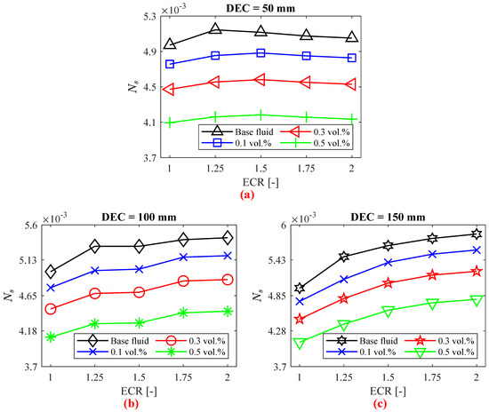
Figure 14.
as a function of tube expansion–contraction ratio (ECR) to the (a) DEC = 50 mm, (b) DEC = 100 mm, and (c) DEC = 150 mm.
As shown in Figure 14, the entropy generation number decreases with increasing volumetric concentration of silver nanoparticles. The lowest value observed was 0.0041 for the straight tube (ECR = 1) with a nanofluid concentration of 0.5 vol.%. These results for the straight tube are consistent with the experimental findings of [49]. Additionally, increasing ECR tends to raise the entropy generation number, except for DEC = 50 mm. In this case, after an initial increase in , the values for both the base fluid and nanofluids decrease to levels comparable to those of the straight tube.
6.8. Thermal-Hydraulic Performance
When analyzing nanofluids in heat exchangers, thermal-hydraulic performance is an important consideration, as illustrated in Figure 15. This parameter assesses the variation in both thermal and hydraulic performance, aiming to enhance heat transfer while minimizing pressure drop. Nanofluids generally exhibit superior thermal-hydraulic performance compared to the base fluid, regardless of ECR or DEC.
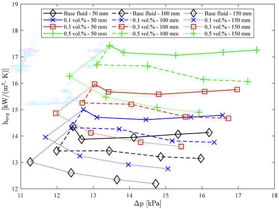
Figure 15.
Thermal-hydraulic performance of nanofluids as a function of DEC, ECR, and nanoparticle concentration.
The greatest improvement in thermal-hydraulic performance with the addition of nanoparticles was observed for the nanofluid with a concentration of 0.5 vol.%, DEC of 100 mm, and ECR of 1.5. This combination resulted in a 23.94% increase in the average convective heat transfer coefficient and a 7.85% increase in pressure drop. Consequently, the thermal-hydraulic performance was 14.92% greater than that of the base fluid for the same geometry. This enhancement is attributed to the increased average convective heat transfer coefficient resulting from the addition of nanoparticles.
7. Conclusions
This study used numerical simulations with Ansys Fluent to analyze silver/water nanofluids in tubes with varying expansion–contraction ratios (ECR) and distances between expansion–contraction (DEC). The results were validated against experimental data and theoretical correlations. Key findings include:
- Model Validation: The numerical model demonstrated satisfactory accuracy in predicting thermal and hydraulic performance, matching well with experimental results and theoretical correlations.
- Impact of ECR: An increased ECR led to a reduction in the average convective heat transfer coefficient by up to 15.07% compared to a straight tube, with some improvements noted only for DEC = 50 mm.
- Effect of Nanofluids: Silver/water nanofluids improved the convective heat transfer coefficient by up to 24.90% at a 0.5% volumetric concentration and mitigated performance drops caused by higher ECR and DEC.
- Pressure Drop: The pressure drop increased with DEC and ECR, with reductions of up to 9.5% for DEC at 50 mm and ECR = 1.25. However, pressure drops increased with DEC for all cases.
- Viscosity and Pressure Drop: Nanoparticle addition increased coolant viscosity and pressure drop by up to 18.34%, though the effect of ECR on pressure drop was minimal.
- Exergy Efficiency: Exergy efficiency increased by up to 29.97% with higher silver nanoparticle concentrations.
- Overall Performance: Nanofluids generally outperformed the base fluid in thermal-hydraulic performance, with the most significant improvement (14.92%) observed for ECR = 1.5 and DEC = 100 mm with a 0.5% nanofluid concentration.
In conclusion, optimizing ECR and utilizing nanofluids can enhance heat transfer in various applications, such as automotive radiators and refrigeration systems. Future research will focus on exploring the effects of different expansion–contraction angles on heat transfer.
Author Contributions
Conceptualization, E.P.B.F., E.O.d.N. and L.C.-G.; Methodology, E.P.B.F., E.O.d.N. and L.C.-G.; Software, E.O.d.N.; Validation, E.O.d.N.; Formal Analysis, E.P.B.F., E.O.d.N., L.C.-G. and M.F.; Investigation, E.P.B.F., E.O.d.N. and L.C.-G.; Resources, M.F.; Data Curation, E.P.B.F., E.O.d.N., L.C.-G. and M.F.; Writing–Original Draft Preparation, E.O.d.N.; Writing–Review & Editing, E.P.B.F., E.O.d.N., L.C.-G. and M.F.; Visualization, E.P.B.F., E.O.d.N., L.C.-G. and M.F.; Supervision, E.P.B.F. and L.C.-G.; Project Administration, E.P.B.F.; Funding Acquisition, E.P.B.F. and M.F. All authors have read and agreed to the published version of the manuscript.
Funding
This research received no external funding.
Data Availability Statement
The original contributions presented in the study are included in the article, further inquiries can be directed to the corresponding author.
Acknowledgments
The authors acknowledge the financial support provided for this research by Prince Mohammad Bin Fahd University in Saudi Arabia, National Council of Scientific and Technological Development (CNPq) in Brazil and the Vanguard Foundation in Suriname.
Conflicts of Interest
The authors declare no conflicts of interest.
Abbreviations
| Nomenclature | |
| z | Axial distance [m] |
| h | Convective heat transfer coefficient [W/(m2·K)] |
| Entropy generation number [–] | |
| Exergy efficiency [%] | |
| Friction factor [–] | |
| Frictional entropy generation [W/K] | |
| Heat flux [W/m2] | |
| Heat transfer rate [W] | |
| D | Hydraulic diameter [m] |
| Kronecker delta | |
| Mass flow rate [kg/s] | |
| Nu | Nusselt number [–] |
| Pr | Prandlt number [-] |
| p | Pressure [Pa] |
| Pressure drop [Pa] | |
| Re | Reynolds number [–] |
| Specific heat [kJ/(kg·K)] | |
| T | Temperature [K] |
| Thermal entropy generation [W/K] | |
| Total entropy generation [W/K] | |
| L | Tube length [m] |
| u | Velocity [m/s] |
| Greek symbols | |
| Density [kg/m3] | |
| Dynamic viscosity [Pa·s] | |
| Thermal conductivity [W/(m·K)] | |
| Volumetric concentration [%] | |
| Abbreviations | |
| DEC | Distance between the contraction and expansion |
| ECR | Expansion–contraction Ratio |
| ER | Expansion Ratio |
| SST | Shear Stress Transport |
| Subscript | |
| ave | Average |
| bf | Base fluid |
| f | Fluid |
| in | Inlet |
| nf | Nanofluid |
| np | Nanoparticle |
| out | Outlet |
| w | Wall |
References
- Salman, S.; Talib, A.R.A.; Saadon, S.; Sultan, M.T.H. Hybrid Nanofluid Flow and Heat Transfer over Backward and Forward Steps: A Review. Powder Technol. 2020, 363, 448–472. [Google Scholar] [CrossRef]
- Kumar, A.; Yadav, S.K.; Kumar, V.; Kulkarni, A. A Comprehensive Exploration of Ejector Design, Operational Factors, Performance Metrics, and Practical Applications. J. Braz. Soc. Mech. Sci. Eng. 2024, 46, 39. [Google Scholar] [CrossRef]
- Li, H.; Lu, H.; Li, Q. Numerical investigations of the influences of valve spool structure on the eccentric jet flow characteristic in high-pressure angle valves. Energy 2024, 298, 131378. [Google Scholar] [CrossRef]
- Togun, H.; Sultan, H.S.; Hamidatou, S.; Mohammed, H.I.; Homod, R.Z.; Alhassan, M.S.; Dhabab, J.M.; Sadeq, A.M.; Yaseen, Z.M.; Deghoum, K.; et al. Comparative Study on Heat Transfer Improvement of Nanofluids Flow in Forward-Facing Reducing Channel with and without Novel Hybrid Ribs. Int. J. Therm. Sci. 2023, 193, 108543. [Google Scholar] [CrossRef]
- Cárdenas Contreras, E.M.; Oliveira, G.A.; Bandarra Filho, E.P. Experimental Analysis of the Thermohydraulic Performance of Graphene and Silver Nanofluids in Automotive Cooling Systems. Int. J. Heat Mass Transf. 2019, 132, 375–387. [Google Scholar] [CrossRef]
- Moreira, T.A.; Moreira, D.C.; Ribatski, G. Nanofluids for Heat Transfer Applications: A Review. J. Braz. Soc. Mech. Sci. Eng. 2018, 40, 303. [Google Scholar] [CrossRef]
- Togun, H.; Abu-Mulaweh, H.I.; Kazi, S.N.; Badarudin, A. Numerical Simulation of Heat Transfer and Separation Al2O3/Nanofluid Flow in Concentric Annular Pipe. Int. Commun. Heat Mass Transf. 2016, 71, 108–117. [Google Scholar] [CrossRef]
- Kimouche, A.; Mataoui, A.; Oztop, H.F.; Abu-Hamdeh, N. Analysis of Heat Transfer of Different Nanofluids Flow through an Abrupt Expansion Pipe. Appl. Therm. Eng. 2017, 112, 965–974. [Google Scholar] [CrossRef]
- Cárdenas Gómez, A.O.; Paz Alegrias, J.G.; Bandarra Filho, E.P. Experimental Analysis of the Thermal-Hydraulic Performance of Water Based Silver and SWCNT Nanofluids in Single-Phase Flow. Appl. Therm. Eng. 2017, 124, 1176–1188. [Google Scholar] [CrossRef]
- Nouri, D.; Pasandideh-Fard, M.; Javad Oboodi, M.; Mahian, O.; Sahin, A.Z. Entropy Generation Analysis of Nanofluid Flow over a Spherical Heat Source inside a Channel with Sudden Expansion and Contraction. Int. J. Heat Mass Transf. 2018, 116, 1036–1043. [Google Scholar] [CrossRef]
- Atashafrooz, M.; Sheikholeslami, M.; Sajjadi, H.; Amiri Delouei, A. Interaction Effects of an Inclined Magnetic Field and Nanofluid on Forced Convection Heat Transfer and Flow Irreversibility in a Duct with an Abrupt Contraction. J. Magn. Magn. Mater. 2019, 478, 216–226. [Google Scholar] [CrossRef]
- Danane, F.; Boudiaf, A.; Mahfoud, O.; Ouyahia, S.; Labsi, N.; Benkahla, Y.K. Effect of Backward Facing Step Shape on 3D Mixed Convection of Bingham Fluid. Int. J. Therm. Sci. 2020, 147, 106116. [Google Scholar] [CrossRef]
- Safaei, M.R.; Abdelghany Elkotb, M.; Alsharif, A.M.; Mansir, I.B.; Alamri, S.; Tirth, V.; Goodarzi, M. An Innovative Design of a High Strength and Low Weight Sudden Micro Expansion by Considering a Nanofluid: Electronic Cooling Application. Case Stud. Therm. Eng. 2021, 28, 101637. [Google Scholar] [CrossRef]
- Arabi, A.; Salhi, Y.; Zenati, Y.; Si-Ahmed, E.-K.; Legrand, J. Experimental Investigation of Sudden Expansion’s Influence on the Hydrodynamic Behavior of Different Sub-Regimes of Intermittent Flow. J. Pet. Sci. Eng. 2021, 205, 108834. [Google Scholar] [CrossRef]
- Der, O.; Bertola, V. An Experimental Investigation of Oil-Water Flow in a Serpentine Channel. Int. J. Multiph. Flow 2020, 129, 103327. [Google Scholar] [CrossRef]
- Kovalev, A.; Yagodnitsyna, A.; Bilsky, A. Plug Flow of Immiscible Liquids with Low Viscosity Ratio in Serpentine Microchannels. Chem. Eng. J. 2021, 417, 127933. [Google Scholar] [CrossRef]
- Auliano, D.; Auliano, M.; Næss, E. Towards a Better Understanding of Heat Transfer and Flow Mechanisms in a Cavity Channel with Numerical Simulations. Int. J. Therm. Sci. 2023, 193, 108531. [Google Scholar] [CrossRef]
- Auliano, D.; Auliano, M.; Næss, E. Near Wall Temperature Measurements and Turbulent Features in a Water Flow at Transition Reynolds Numbers in a Square Heated Asymmetric Cavity Channel. Therm. Sci. Eng. Prog. 2023, 37, 101541. [Google Scholar] [CrossRef]
- Iachachene, F.; Haddad, Z.; Arıcı, M.; Jamei, M.; Mataoui, A. Turbulent Forced Convective Flow in a Conical Diffuser: Hybrid and Single Nanofluids. Eng. Anal. Bound. Elem. 2023, 148, 205–219. [Google Scholar] [CrossRef]
- Moreira, T.A.; Fariñas Alvariño, P.; Cabezas-Gómez, L.; Ribatski, G. Experimental and Numerical Study of Slightly Loaded Water Alumina Nanofluids in the Developing Region of a 1.1 Mm in Diameter Pipe and Convective Enhancement Evaluation. Int. J. Heat Mass Transf. 2017, 115, 317–335. [Google Scholar] [CrossRef]
- Ali, A.M.; Angelino, M.; Rona, A. Numerical Analysis on the Thermal Performance of Microchannel Heat Sinks with Al2O3 Nanofluid and Various Fins. Appl. Therm. Eng. 2021, 198, 117458. [Google Scholar] [CrossRef]
- Ekiciler, R.; Çetinkaya, M.S.A. A Comparative Heat Transfer Study between Monotype and Hybrid Nanofluid in a Duct with Various Shapes of Ribs. Therm. Sci. Eng. Prog. 2021, 23, 100913. [Google Scholar] [CrossRef]
- Fluent, A. Ansys Fluent Theory Guide; ANSYS Inc.: Canonsburg, PA, USA, 2013; Volume 15317. [Google Scholar]
- do Nascimento, E.O.; de Freitas, E.A.; Lins, E.F.; Vaz, J.R.P. Performance Assessment of an Indalma Hydro-Turbine. SN Appl. Sci. 2020, 2, 2156. [Google Scholar] [CrossRef]
- Sadri, R.; Mallah, A.R.; Hosseini, M.; Ahmadi, G.; Kazi, S.N.; Dabbagh, A.; Yeong, C.H.; Ahmad, R.; Yaakup, N.A. CFD Modeling of Turbulent Convection Heat Transfer of Nanofluids Containing Green Functionalized Graphene Nanoplatelets Flowing in a Horizontal Tube: Comparison with Experimental Data. J. Mol. Liq. 2018, 269, 152–159. [Google Scholar] [CrossRef]
- Saffarian, M.R.; Moravej, M.; Doranehgard, M.H. Heat Transfer Enhancement in a Flat Plate Solar Collector with Different Flow Path Shapes Using Nanofluid. Renew. Energy 2020, 146, 2316–2329. [Google Scholar] [CrossRef]
- Roache, P.J. Quantification of Uncertainty in Computational Fluid Dynamics. Annu. Rev. Fluid Mech. 1997, 29, 123–160. [Google Scholar] [CrossRef]
- Wen, T.; Lu, L.; Zhang, S.; Zhong, H. Experimental Study and CFD Modelling on the Thermal and Flow Behavior of EG/Water ZnO Nanofluid in Multiport Mini Channels. Appl. Therm. Eng. 2021, 182, 116089. [Google Scholar] [CrossRef]
- do Nascimento, E.O.; Cardenas Contreras, E.M.; Cabezas-Gómez, L.; Bandarra Filho, E.P. Comparison of Experimental Results with Numerical Simulation of Thermal Performance in Car Radiator Using MWCNT/EG/Water Nanofluid. J. Braz. Soc. Mech. Sci. Eng. 2024, 46, 440. [Google Scholar] [CrossRef]
- Manca, O.; Nardini, S.; Ricci, D. A Numerical Study of Nanofluid Forced Convection in Ribbed Channels. Appl. Therm. Eng. 2012, 37, 280–292. [Google Scholar] [CrossRef]
- Petukhov, B.S. Heat Transfer and Friction in Turbulent Pipe Flow with Variable Physical Properties. Adv. Heat Transf. 1970, 6, 503–564. [Google Scholar]
- Gnielinski, V. Neue Gleichungen Für Den Wärme- Und Den Stoffübergang in Turbulent Durchströmten Rohren Und Kanälen. Forsch. Im Ingenieurwes 1975, 41, 8–16. [Google Scholar] [CrossRef]
- Dittus, F.W.; Boelter, L.M.K. Heat Transfer in Automobile Radiators of the Tubular Type. Int. Commun. Heat Mass Transf. 1985, 12, 3–22. [Google Scholar] [CrossRef]
- Blasius, H. Das Aehnlichkeitsgesetz bei Reibungsvorgängen in Flüssigkeiten. In Mitteilungen über Forschungsarbeiten auf dem Gebiete des Ingenieurwesens. Mitteilungen über Forschungsarbeiten auf dem Gebiete des Ingenieurwesens; Springer: Berlin/Heidelberg, Germany, 1913; Volume 131. [Google Scholar] [CrossRef]
- Xuan, Y.; Roetzel, W. Conceptions for Heat Transfer Correlation of Nanofluids. Int. J. Heat Mass Transf. 2000, 43, 3701–3707. [Google Scholar] [CrossRef]
- Pak, B.C.; Cho, Y.I. Hydrodynamic and Heat Transfer Study of Dispersed Fluids With Submicron Metallic Oxide Particle. Exp. Heat Transf. 1998, 11, 151–170. [Google Scholar] [CrossRef]
- Montazer, E.; Shafii, M.B.; Salami, E.; Muhamad, M.R.; Yarmand, H.; Gharehkhani, S.; Chowdhury, Z.Z.; Kazi, S.N.; Badarudin, A. Heat Transfer in Turbulent Nanofluids: Separation Flow Studies and Development of Novel Correlations. Adv. Powder Technol. 2020, 31, 3120–3133. [Google Scholar] [CrossRef]
- Ahmad, F.; Mahmud, S.; Ehsan, M.M.; Salehin, M. Numerical Assessment of Nanofluids in Corrugated Minichannels: Flow Phenomenon and Advanced Thermo-Hydrodynamic Analysis. Int. J. Thermofluids 2023, 20, 100449. [Google Scholar] [CrossRef]
- Amiri, A.; Shanbedi, M.; Rafieerad, A.R.; Rashidi, M.M.; Zaharinie, T.; Zubir, M.N.M.; Kazi, S.N.; Chew, B.T. Functionalization and Exfoliation of Graphite into Mono Layer Graphene for Improved Heat Dissipation. J. Taiwan Inst. Chem. Eng. 2017, 71, 480–493. [Google Scholar] [CrossRef]
- Montazer, E.; Yarmand, H.; Salami, E.; Muhamad, M.R.; Kazi, S.N.; Badarudin, A. A Brief Review Study of Flow Phenomena over a Backward-Facing Step and Its Optimization. Renew. Sustain. Energy Rev. 2018, 82, 994–1005. [Google Scholar] [CrossRef]
- Huminic, G.; Huminic, A. The Heat Transfer Performances and Entropy Generation Analysis of Hybrid Nanofluids in a Flattened Tube. Int. J. Heat Mass Transf. 2018, 119, 813–827. [Google Scholar] [CrossRef]
- Saleh, B.; Sundar, L.S. Entropy Generation and Exergy Efficiency Analysis of Ethylene Glycol-Water Based Nanodiamond + Fe3O4 Hybrid Nanofluids in a Circular Tube. Powder Technol. 2021, 380, 430–442. [Google Scholar] [CrossRef]
- Alklaibi, A.M.; Sundar, L.S.; Sousa, A.C.M. Experimental Analysis of Exergy Efficiency and Entropy Generation of Diamond/Water Nanofluids Flow in a Thermosyphon Flat Plate Solar Collector. Int. Commun. Heat Mass Transf. 2021, 120, 105057. [Google Scholar] [CrossRef]
- Hazbehian, M.; Mohammadiun, M.; Maddah, H.; Alizadeh, M. Analyses of Exergy Efficiency for Forced Convection Heat Transfer in a Tube with CNT Nanofluid under Laminar Flow Conditions. Heat Mass Transf. 2017, 53, 1503–1516. [Google Scholar] [CrossRef]
- Mazaheri, N.; Bahiraei, M.; Abdi Chaghakaboodi, H.; Moayedi, H. Analyzing Performance of a Ribbed Triple-Tube Heat Exchanger Operated with Graphene Nanoplatelets Nanofluid Based on Entropy Generation and Exergy Destruction. Int. Commun. Heat Mass Transf. 2019, 107, 55–67. [Google Scholar] [CrossRef]
- Samal, S.K.; Moharana, M.K. Thermo-Hydraulic and Entropy Generation Analysis of Recharging Microchannel Using Water-Based Graphene–Silver Hybrid Nanofluid. J. Therm. Anal. Calorim. 2021, 143, 4131–4148. [Google Scholar] [CrossRef]
- Ahammed, N.; Asirvatham, L.G.; Wongwises, S. Entropy Generation Analysis of Graphene–Alumina Hybrid Nanofluid in Multiport Minichannel Heat Exchanger Coupled with Thermoelectric Cooler. Int. J. Heat Mass Transf. 2016, 103, 1084–1097. [Google Scholar] [CrossRef]
- Syam Sundar, L. Experimental Study on the Thermophysical Properties, Heat Transfer, Thermal Entropy Generation and Exergy Efficiency of Turbulent Flow of ZrO2-Water Nanofluids. Alex. Eng. J. 2023, 65, 867–885. [Google Scholar] [CrossRef]
- Syam Sundar, L. Heat Transfer, Friction Factor and Exergy Efficiency Analysis of Nanodiamond-Fe3O4/Water Hybrid Nanofluids in a Tube with Twisted Tape Inserts. Ain Shams Eng. J. 2023, 14, 102068. [Google Scholar] [CrossRef]
- Mukherjee, S.; Poloju, V.; Mishra, P.C. Heat Transfer, Exergoeconomic Performance and Sustainability Impact of a Novel CuO + MgO + GO/Water Ternary Nanofluid. Appl. Therm. Eng. 2023, 235, 121391. [Google Scholar] [CrossRef]
- Sundar, L.S.; Shaik, F.; Sharma, K.V.; Punnaiah, V.; Sousa, A.C.M. The Second Law of Thermodynamic Analysis for Longitudinal Strip Inserted Nanodiamond-Fe3O4/Water Hybrid Nanofluids. Int. J. Therm. Sci. 2022, 181, 107721. [Google Scholar] [CrossRef]
- Syam Sundar, L.; Mesfin, S.; Venkata Ramana, E.; Said, Z.; Sousa, A.C.M. Experimental Investigation of Thermo-Physical Properties, Heat Transfer, Pumping Power, Entropy Generation, and Exergy Efficiency of Nanodiamond + Fe3O4/60:40% Water-Ethylene Glycol Hybrid Nanofluid Flow in a Tube. Therm. Sci. Eng. Prog. 2021, 21, 100799. [Google Scholar] [CrossRef]
Disclaimer/Publisher’s Note: The statements, opinions and data contained in all publications are solely those of the individual author(s) and contributor(s) and not of MDPI and/or the editor(s). MDPI and/or the editor(s) disclaim responsibility for any injury to people or property resulting from any ideas, methods, instructions or products referred to in the content. |
© 2025 by the authors. Licensee MDPI, Basel, Switzerland. This article is an open access article distributed under the terms and conditions of the Creative Commons Attribution (CC BY) license (https://creativecommons.org/licenses/by/4.0/).