Article

Investigation of the Combustion Properties of Ethylene in Porous Materials Using Numerical Simulations

1
School of Chemical and Environmental Engineering, Wuhan Polytechnic University, Wuhan 430023, China
2
Pilot Plant of Eco-Environment Chemical Industry and Carbon-Neutral Transformative Technologies, Wuhan 430023, China
3
Hubei Provincial Engineering Research Center of Soil and Groundwater Pollution Prevention and Control, Wuhan 430023, China
4
Wuhan Thought of Forging Anew Environment Technology Co., Ltd., Wuhan 430056, China
*
Author to whom correspondence should be addressed.
These authors contributed equally to this work.
Energies 2024, 17(9), 2153; https://doi.org/10.3390/en17092153
Submission received: 27 February 2024 / Revised: 17 April 2024 / Accepted: 22 April 2024 / Published: 30 April 2024
(This article belongs to the Section I2: Energy and Combustion Science)

Abstract

:
As industrial modernization advances rapidly, the need for energy becomes increasingly urgent. This paper aims to enhance the current burner design by optimizing the combustion calorific value, minimizing pollutant emissions, and validating the accuracy of the burner model using experimental data from previous studies. The enhanced porous medium burner model is used to investigate the burner’s combustion and pollutant emission characteristics at various flow rates, equivalence ratios, combustion orifice sizes, and porosity of porous media. In comparison with the previous model, the combustion traits during ethylene combustion and the emission properties of pollutants under various operational circumstances have been enhanced with the enhanced porous medium burner model. The maximum temperature of ethylene combustion in the enhanced model is 174 k higher than that before the improvement, and the CO emissions are reduced by 31.9%. It is believed that the findings will serve as a guide for the practical implementation of porous media combustion devices.

1. Introduction

The consumption of conventional fossil fuels like coal, natural gas, and oil is steadily rising due to the swift progress of modern industrialization. Furthermore, a significant quantity of gases with low calorific value have not been efficiently utilized or subjected to eco-friendly treatment. Various types of waste gases are generated in the petrochemical industry, landfill processes, coal mining, and the anaerobic fermentation stage of sewage treatment plants. These gases include low calorific value ethylene, other waste gases, methane, and more. These low calorific value combustible gases cannot be treated and used effectively through direct combustion. In most areas, such low calorific value gases are directly discharged into the air, which will have a serious impact on our environment. To enhance the energy value of combustion and minimize pollutant emissions, there is an urgent requirement for novel combustion concepts and technologies in the context of the worldwide shift towards low-carbon energy [1]. The main difficulty in eliminating these gases from the air mixture is the very low concentration of these compounds, so an alternative method that has been extensively studied in experimental and numerical values, porous medium combustion, was considered in this work.
Compared with free flame combustion, the advantages of porous medium combustion are that the porous medium combustion technology has good combustion stability, low pollutant emissions, and high combustion efficiency, and increases the solid phase and gas phase temperature through the porous matrix, thus extending the poor flammability limit. Li et al. [2] studied and compared the flame properties in free flame and porous media burners. They demonstrated that, contrary to free flame burners, porous media burners provide higher wall temperature and lower flame temperature. Ning et al. [3] conducted numerical and experimental studies on y-fiber porous medium burners with different diameters to determine their flame stability, flammability and combustible range, and concluded that the combustible range could be significantly expanded with porous medium burners. Tsang et al. [4] studied the laminar combustion characteristics of methane/air mixtures in porous media, and discussed the effect of hydrogenation on combustion based on a one-dimensional geometric model, and introduced the GRI-Mech 2.11 reaction mechanism. Sathe et al. [5] explored the poor combustion process of porous media through numerical methods. Farzaneh et al. [6] studied the combustion process of a porous medium burner under two variable diameters. Liu et al. [7] simulated the combustion process of 2D methane/air premix in the accumulation ball. Deng et al. [8] explored the combustion characteristics of propane and butane-premixed gas under reciprocated flow in a porous medium. Evans K et al. [9] studied three-dimensional numerical values of methane-oxygen combustion in a small porous medium cylindrical combustion chamber to expand the optimization of thermal photovoltaic power generation application control parameters. Under the same configuration, for different equivalence ratios, inlet speed, porous medium porosity and wall thermal conductivity were simulated. The results showed that compared with non-porous medium, porous medium improved the thermal characteristics of the combustion chamber, providing the premise for developing and improving the performance of burners under given constraints. It suggested that the current study on porous medium burners primarily concentrate on analyzing the combustion mechanism and characteristics of porous medium burners [2,3,4,5,6,7,8,9]. It is recognized that porous medium burners can provide higher wall temperatures and lower flame temperatures, as well as characteristics such as an expanded combustible range. However, there is a noticeable absence of research on enhancing the burner’s structure to optimize combustion efficiency and minimize the emission of toxic and harmful gases.
The design of the porous medium burner requires an analysis of the propagation and stability of the combustion wave in the reactor. Therefore, this study aimed to design a physical model of the burner and focused on aspects such as the distribution and variation of combustion temperature [10], the speed of flame propagation, and the conditions for stable flame combustion [11]. The benefits of the enhanced porous medium burner in terms of heat value and pollutant emission were investigated and may be attributed to the properties of porous medium with excellent heat storage, radiation heat conductivity, and a stable flat flame formed on its surface in a certain equivalence ratio and flow range.

2. Physical and Mathematical Models

2.1. Physical Models

The general burner is uniformly filled with a homogeneous porous material, which is interconnected by the same porosity of the porous medium. The ethylene mixture flows from the bottom into the combustion area [12]. The enhanced physical representation of the porous medium burner consists of two sections, with the upper and lower regions arranged symmetrically and the central region designated for gas inflow, as depicted in Figure 1. The gas was injected into the combustion area through the fine column located in the middle area, which will be quickly changed from the preheating state to the combustion state, so as to improve the combustion efficiency of the burner in combustion and temperature.

2.2. Assumptions

Combustion will generate strong chemical interactions among the gas–gas, and gas–solid, leading to a tightly connected procedure, and also encompassing heat conduction, radiation, convection, and various other forms of heat transfer. The simplifying assumptions and hypothesis scheme for the ethylene combustion process are presented below, considering the actual conditions and disregarding secondary factors.
(1)
Porous dielectric materials in burners will not have a catalytic function in the process of combustion.
(2)
Prior to entering the combustion zone, a mixture of ethylene gas has been blended.
(3)
Porous dielectric materials are regarded as a diffusion structure that is both isotropic and uniform.
(4)
The ideal gases involved in combustion, both reactants and products, remain incompressible before and after the reaction.
(5)
The entire furnace disregards the impact of gravity.

2.3. Governing Equation

According to the assumptions, the numerical simulation incorporates the continuity equation (Equation (1)), and the conservation equation of momentum is Equation (2). The transfer of heat within the porous material is described by the solid-phase energy equation (Equation (3)). In the ideal gas state where each component gas is regarded as incompressible, the ideal gas equation of state is Equation (4). The species conservation equation is Equation (5), and the gas phase energy equation is Equation (6) [13,14,15,16,17,18,19,20]:
ρ g ε t + ρ g ε u i x i = 0
ρ g ε u j t + ρ g ε u i u j x i x i ρ g ε F u j x i = ε P x j μ ε 2 K p u j + x i ρ g ε F u x j 2 3 u k x k δ i j
1 ε ρ s C s T s t = γ e s T s + h v T g T s
ρ g = W ¯ P R T g
ε ρ g Y i t + · ε ρ g u Y i = · ε ρ g Y i V i + ε ω ˙ W i
ε ρ g C p g T g t + ε C p g ρ g u T g = h v T s T g + ε · K e f f g T g ε i ω i ˙ h i W i
where ρ g is the density of the gas after uniform mixing, ε is the porosity of the porous medium, and u i is the velocity vector, K p is the permeability of the porous medium, F is the kinematic viscous drag coefficient, μ is the inertial drag coefficient, γ e s is the effective heat conduction coefficient of the porous medium material, γ e s = γ e c + γ e r γ e c and γ e c is the heat transfer coefficient converted from radiation, ρ s is the density of the porous medium, C s represents the specific heat capacity of the material, T s is the temperature of the porous medium, W ¯ is the value of the mixed gas’s average molecular weight, Yi is the mass fraction of the ith species, V i = u i u is the diffusion velocity of the ith species, u i is the velocity compared to the stationary coordinate system of the ith species, ω i ˙ is the reaction rate of the ith species, and W i is the molecular mass. h v is the volumetric heat transfer coefficient between the porous media and the gas, h i is the molar enthalpy of the ith species, and T g is the temperature of the gas. C p g is the specific heat capacity of the gas mixture, K e f f g is the effective thermal conductivity of the gas mixture and expresses as K e f f g = K g + ρ g C p g Dd, Dd is the thermal diffusivity of the porous media, and K g is the thermal conductivity of the gas mixture.

3. Numerical Method and Grid-Independent Verification

The control equations are discretized and solved by using the FLUENT software (2018) for fluid simulation. To ensure the transfer of high temperature from the flame area to the solid medium in the porous medium burner, both the gas and solid energy equations are utilized. The radiation is opened in the way of discrete coordinates. To guarantee the proper convergence of the computation outcomes, Under Relaxation iteration is implemented. The energy equation’s residual convergence criterion is set to zero, signifying that the computation can be iterated continuously based on the number of steps to ensure the stability and precision of the solution calculation. To discretize the conservation equations, the controlled volume approach is employed. To solve the mass, momentum, species and energy conservation equations with pressure–velocity coupling, the SIMPLE algorithm is utilized. SIMPLE is the Semi-Implicit Method of Pressure-Linked Equations. The convective terms are approximated by the second-order upwind scheme, and the diffusion terms are approximated by the central difference scheme. The underrelaxation iteration is used to solve the stiff problem in chemical reactions [19].
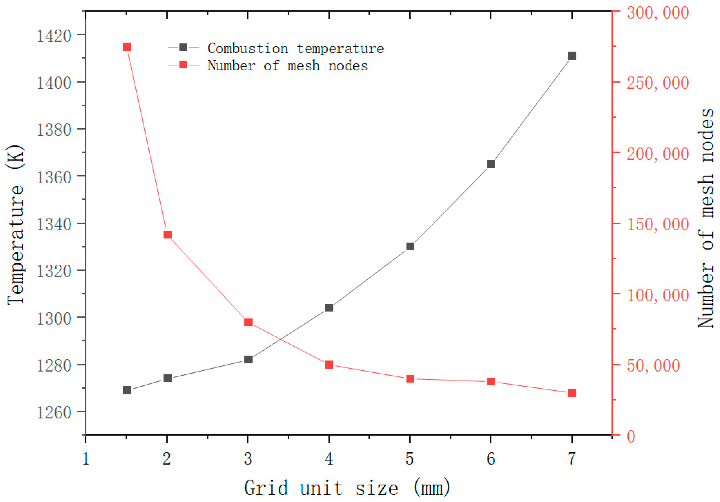
The error caused by discretization is a primary factor contributing to the discrepancy between numerical calculation and test results. During the calculation, as the grid becomes thinner, the discretization error will decrease, but it will also result in more discretization points and consequently a larger rounding error. Hence, having a greater number of grids does not necessarily yield better results. The solution target is determined by choosing the highest temperature of the burner tube. If the temperature remains constant regardless of the size of the grid cell, the grid cell size has no impact on the accuracy of the solution result. Figure 2 illustrates the correlation between the computation of the grid cell dimensions, the number of grid points, and the temperature of the model. As the grid cell size becomes more refined, the quantity of grid nodes experiences a significant increase. The combustion temperature remains stable at approximately 1270 K when the grid cell size is below 3 mm, and the calculation outcomes for 3 mm, 2 mm, and 1.5 mm are virtually indistinguishable. Thus, the largest cell dimension was established as 3 mm, resulting in the creation of 77,800 grids.

3.1. Thermal Property Parameters

Since the temperature of the entire combustion region changes dramatically during the combustion reaction process, the value of 1298 J/(kg × K) at 1300 K used in the literature [21] for the heat capacity of alumina pellets is selected. The thermal conductivity selected in this paper is the functional relationship between the effective thermal conductivity of alumina and temperature [22]. The Viscous model used the standard k-epsilon, and the Near-Wall treatment was set to Standard Wall Function. The radiation model used discrete coordinates (DO), and the mixed material in the component model was used in ethylene-air.
k s = 0.34691 736.72 × 10 6 T + 1.2052 × 10 6 T 2

3.2. Boundary Conditions

The initial temperature and speed of the premixed gas are set at the entrance. To guarantee the stability of the computation outcomes and expedite the convergence, a greater starting temperature of 800 K is established, which acts as a high-temperature heat source for the initial ‘ignition’. The combustion properties of the new burner with a porous medium are investigated by examining various equivalence ratios and inlet flow rates, based on the operational conditions provided in Table 1.

4. Results and Discussion

4.1. Computational Validations

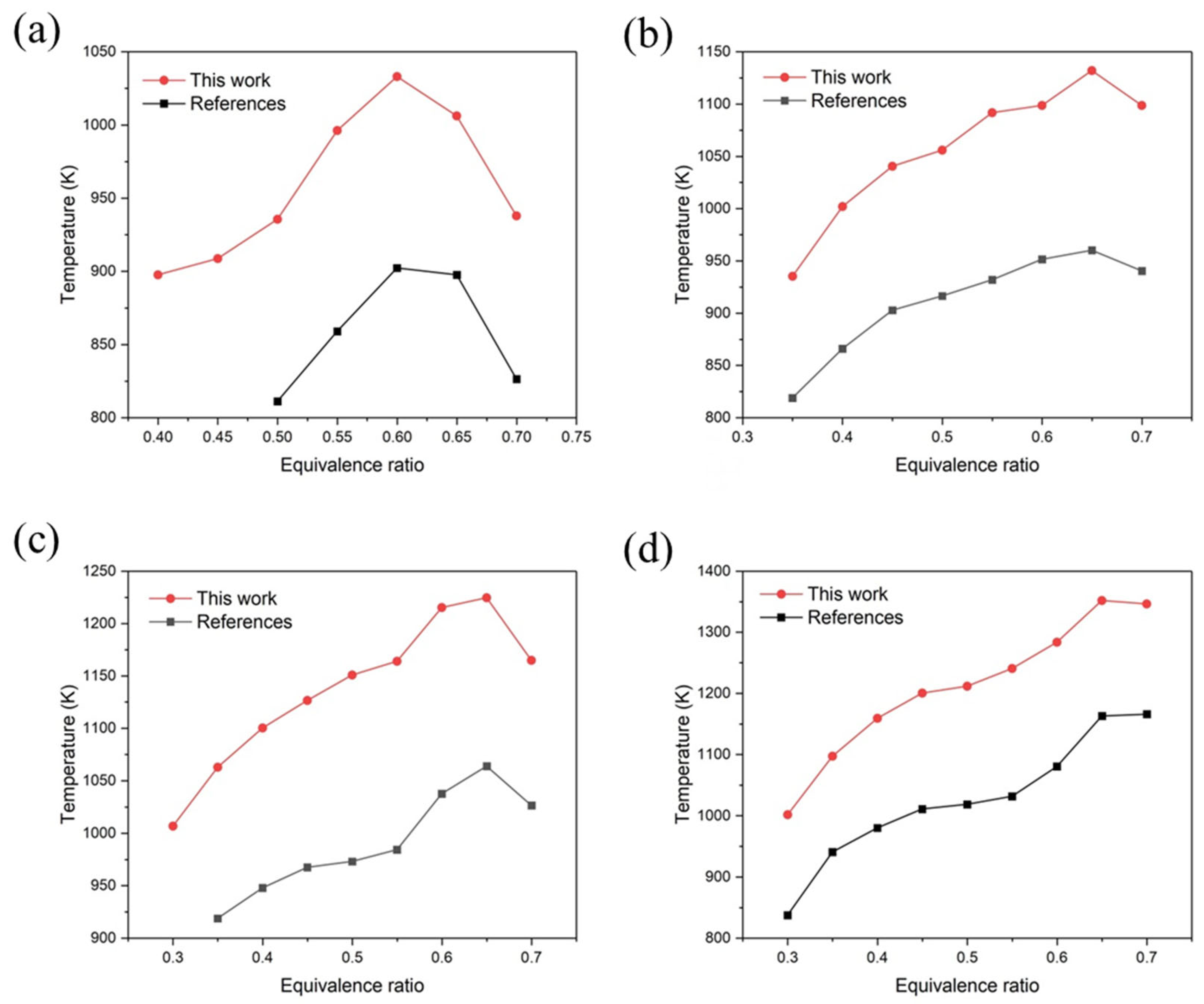
The comparative verification was conducted using the porous medium burner mentioned in the previous work [12], based on the outcomes of numerical simulation. Figure 3 illustrates the variation trend in the highest temperature and equivalence ratio in the burner at various initial velocities prior to and following enhancement. The burner model proposed in this study closely aligns with the simulation findings in the previous work [12], demonstrating a strong agreement in trends and affirming the precision of the numerical simulation model developed in this research.
The temperature trend generally agrees with the numerical results of reference [12]. When the combustible gas mixture flows through the porous medium, the reaction generate heat through convection and radiation. The emissivity of the porous medium is higher than that of the gas, originating from the highly heated flame area of the porous medium. The reactants injected by radiation and convection heating enable effective preheating of the mixed gas. The results in Figure 3 also show the difference from the reference results [12]. There is a peak at the equivalence ratio of 0.65, and the other temperature trends are essentially the same. The reasons for these differences may come from different numerical methods, different chemical mechanisms, or different dimensions of the model.

4.2. Influence of Different Working Conditions on the Combustion Characteristics

The combustion characteristics of ethylene are closely related to its concentration. The equivalence ratio determines the concentration of ethylene in the gas stream. The attainment of combustion conditions as well as the heat production can be enhanced during subsequent combustion by increasing the concentration of ethylene. The change in the flow rate have an impact on both the temperature distribution and the distribution of mass fractions for each component within the combustion chamber. It, in turn, will influence the combustion characteristics of ethylene and the generation of pollutants [23]. Thus, it is crucial to investigate the combustion properties of ethylene under varying flow rates and equivalence ratios.
Figure 4 shows the varying combustion characteristics of ethylene at different temperatures. The maximum temperature of ethylene combustion under different working conditions is 1426 K, which is significantly higher than 1252 K before optimization. There was a noticeable increase in the overall temperature, with the highest temperature rise reaching 13%, suggesting the improved combustion characteristic of ethylene. As far as the trend analysis is concerned, the combustion temperature increases rapidly at first and then decreases with the increase in the equivalence ratio. Compared with other burners, it can be found that in the equivalence ratio between 0 to 0.55, the temperature in the burner has a clear rising trend. The other burner in the early heating is relatively flat; because the burner flame spread downstream and the temperature of the porous medium in the upstream gradually decreased, it cannot effectively preheat, and the premixed gas combustion flame weakened [12]. However, the improved burner can effectively preheat the premixed gas in the beginning stage and make the temperature in the burner rise. At almost the testing flow rate, the reaction temperature is the highest at the equivalence ratio of 0.65, which may be attributed to the reduction in premixed gas flow when the equivalence increases. The smaller porous medium pores in the burner are unfavorable for heat exchanges among the flue gas, small ball, and thermocouple. In terms of combustion distribution, due to the presence of the porous medium, the gas does not flow out of the combustion chamber too quickly but is evenly distributed in the upstream area of the combustion chamber. When the flame spreads upstream, the two temperatures change greatly, from 1383 K to 1426 K. The maximum temperature of the flame shows an upward trend. The combustion temperature at a high flow rate is much higher than the temperature at lower ones. In the process of flame propagation, the propagation direction of the combustion wave is opposite to the flow direction of the premixed gas, when the increasing flow rate of the premixed gas will cause the flame combustion to become slow. At the same time, more fuel combustion per unit time releases more calorific value, so that the porous medium in the upstream segment can more fully carry out heat conduction and better preheating of the upstream premixed gas. Its impact on the flame temperature is far greater than the increased heat loss of the gas flow rate. When the flame travels in the same direction as the premix gas, it is probably because the calorific value generated by ethylene combustion dominates the flame temperature.

4.3. Pollutant Emission Characteristics during Ethylene Combustion

The burning of hydrocarbon fuels will unavoidably generate harmful gases, specifically CO and NO, that are directly released into the air, not only impacting the natural surroundings but also posing a significant threat to human well-being. Finding ways to decrease the release of carbon monoxide and nitrogen oxide remains a significant area of study.
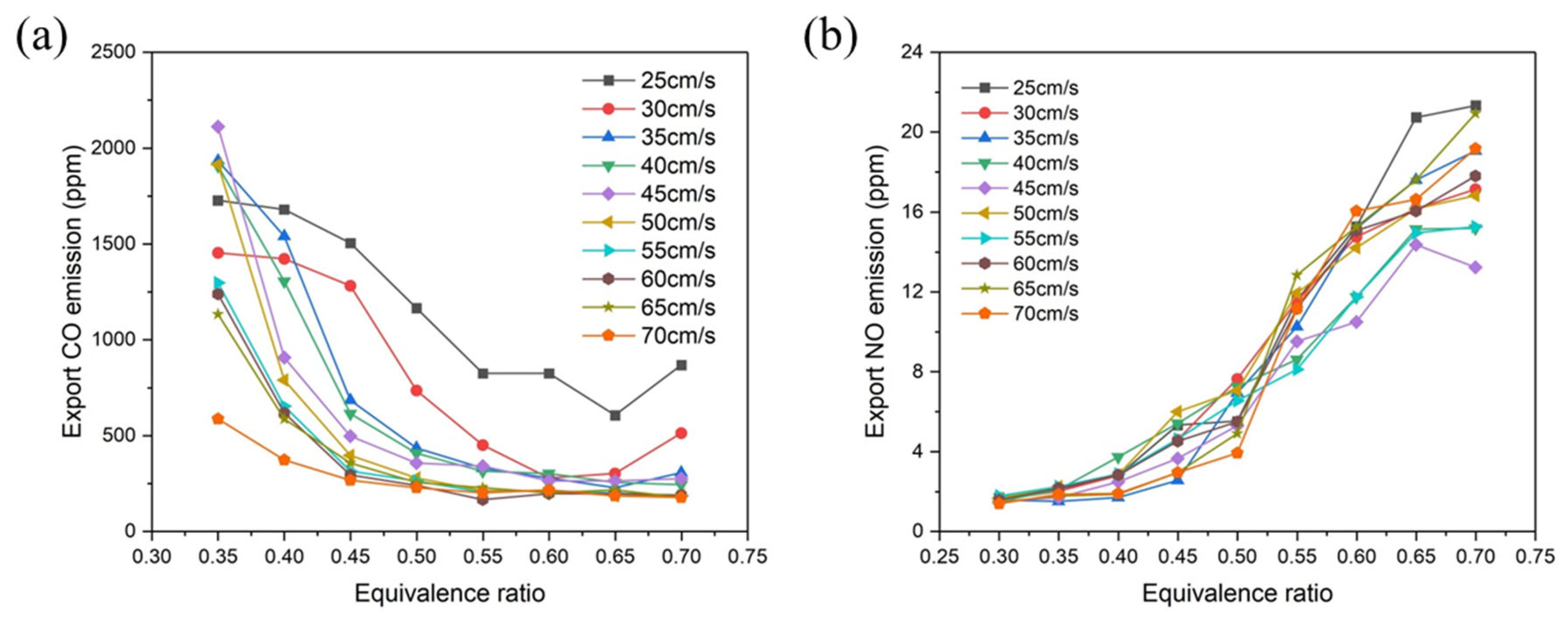
Figure 5 illustrates the CO and NO emissions under various combustion conditions by extracting the pollutant emission from the flue gas outlet mentioned above. The CO emission is greatly influenced by the equivalence ratio, primarily by altering the combustion temperature and subsequently impacting CO production (Figure 5a). The CO equivalence ratio produces higher CO emissions at 0.35, because the flame combustion temperature is low and cannot provide a good temperature environment for complete ethylene combustion. In the low temperature zone with low flow rate, the short residence time leads to incomplete combustion to some extent, and because the further reaction of CO and oxygen is relatively slow, the CO emission can reach 2111 ppm. As the equivalence ratio rises, CO production experiences a significant decline. For the flow rate of 45 cm/s, the concentration of CO emission reaches the peak of 2111.64 ppm at the equivalence ratio of 0.35, and then remains stable after the equivalence ratio reaches 0.55. The generation of CO is greatly affected when the range of comparable proportion is between 0.35 and 0.55. During this period, the combustion temperature becomes the main factor affecting the CO emission. After the equivalence ratio increases, the combustion temperature starts to rise gradually, and the reversible reaction of CO becomes more intense. Among them, the increased reaction rate of the positive reaction of CO and OH leads to the decrease in CO.
Overall, the NO emissions are all in a low range, with the maximum emission not exceeding 22 ppm. The NO emission shows a gradual increase with the equivalence ratio, as indicated by the trend of all lines in Figure 5b. The higher the equivalence ratio, the higher the temperature peak, which accelerates the reaction rate of CN-N2 and thus produces fast-type NO. With the equivalence ratio at 0.3 to 0.4, the NO emissions are very low, approaching 0 ppm. This is because the combustion wave is not favorable for the oxidation of N when moving in the positive direction. The increase in the flow rate causes the temperature rise and the acceleration of N2 oxidation, which also shortens the residence time of the flue gas in the burner and suppresses the further oxidation of NO. Under the balance of various changes, it is found that the flow rate has little effect on the formation of NO in the premixed gas combustion.
Regarding pollutant emissions, the improvement of the combustion model resulted in a decrease in CO emissions from 3100 ppm to 2111.64 ppm, representing a reduction of 31.9%. Although after making structural improvements, the combustion temperature rose, leading to an increase in NO emissions from 12.14 ppm to 21.49 ppm, the emission of NO was still low on the whole.

4.4. Effect of Combustion Aperture on Combustion Characteristics

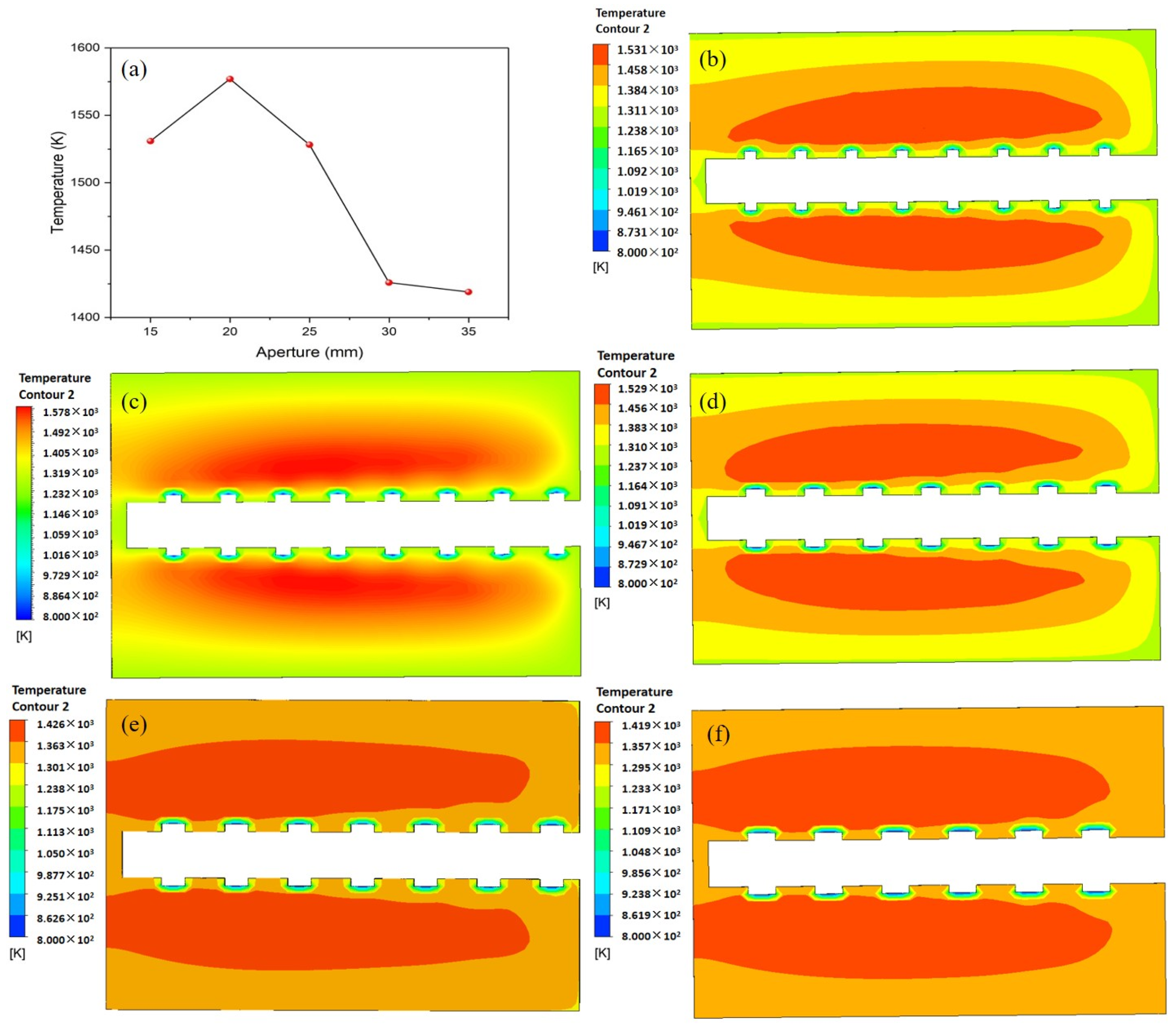
Based on the above optimal combustion characteristic conditions (equivalence ratio 0.65, speed 75 cm/s), the influence of different combustion hole apertures on ethylene combustion characteristics is explored (Figure 6).
From the temperature cloud map under different pore sizes, with the increase in the aperture, the overall combustion temperature shows a trend of rapid reduction. The highest temperature of the combustion chamber reaches 1576 K when the pore diameter is 20 mm, the lowest temperature reaches 1418 K when the pore diameter is 35 mm, and the temperature change exceeds 158 K, a decrease of 10.2%, indicating that the combustion temperature is very sensitive to the change in the aperture in the combustion chamber. This is because the larger aperture will lead to the external flame combustion while still in the lower temperature state, and the internal combustion speed is slow, thus affecting the temperature rise of the combustion chamber. This trend is evident near the exit. When the aperture is small, the air intake will be relatively small, and the insufficient heat transfer makes the temperature in the burner rise slowly. When the pore size is 20 mm, the premixed gas is introduced, and the slow movement of the flame has a better influence on the combustion area. At this time, the impact of combustion residence speed is greater than the problem of lower calorific value due to the large pore size.

4.5. Influence of Porosity of Porous Media on Combustion Characteristics

A porous medium is a substance composed of a solid skeleton and a large number of pore channels. Changing the porosity can affect the heat transfer capacity and the drag loss [24] in the combustion process. Therefore, this section studies the influence of porosity on the combustion characteristics of ethylene gas with an initial flow rate of 70 cm/s and an equivalence ratio of 0.65 (Figure 7).
The combustion chamber under different porosity temperature changes is relatively obvious. With decreasing porosity, the temperature in the combustion chamber increases from 1342 K at a porosity of 0.9 to 1608 K at a porosity of 0.6, which is attributed to the reduction in porosity directly leading to the high resistance of the gas flow in the internal microchannel, resulting in the slow leave and heat concentration. When the void ratio is relatively high, it will lead to more radiation and heat dissipation, and the temperature in the center of the flame also decreases. As the void rate increases, the contact area of the sphere and the gas increases, thus leading to an increase in the heat flux. Due to the good thermal conductivity of the porous medium, more heat is transferred to the upstream porous medium in time, resulting in a lower flame temperature, and the higher the porosity, the lower the temperature in the burner.

5. Conclusions

This paper aims to enhance a standard porous medium burner by creating a numerical analysis calculation model based on a hypothesis. The model’s accuracy is validated through trend analysis by comparing it with the test data mentioned in the previous work [12]. The burner’s combustion and pollutant emission characteristics were examined and discussed by studying different flow rates, equivalence ratios, combustion pore sizes, and porosities of the porous medium, using this model as a basis. We have derived the following findings:
(1)
Following the enhancement of the porous medium burner’s structure, there was a noticeable increase in the overall temperature; the highest temperature reached 1426 K. The central area is where the high-temperature distribution is primarily focused, ensuring that the combustion chamber effectively expels the fully combusted ethylene gas.
(2)
Typically, the emission of CO initially decreases and subsequently gradually rises as the equivalence ratio increases. The CO emission reaches the lowest value when the equivalence ratio increases to 0.55. The generated NO is mainly instantaneous NO. As the equivalence ratio increases, the burner experiences a greater temperature rise, leading to the production of instantaneous NO. However, the emission of NO remains consistently low.
(3)
The pore diameter affects the temperature change in the combustion chamber by changing the inflow diameter of the ethylene gas. As the aperture decreases and the number of combustion holes increases, the temperature rises.
(4)
The reduction in porosity will cause an increase in gas flow resistance, leading to the accumulation of heat in the combustion chamber. The temperature increase clearly indicates a significant surge, with the maximum temperature rise reaching 266 K.

Author Contributions

L.T.: Conceptualization, Data Curation, Formal Analysis, Methodology, Writing—Original Draft; S.D.: Writing—Review and Editing, Supervision, Conceptualization, Resources; S.L.: Writing—Review and Editing, Funding Acquisition, Supervision, Conceptualization, Resources; H.Z.: Data Curation, Investigation; W.F.: Writing—Review and Editing, Investigation. All authors have read and agreed to the published version of the manuscript.

Funding

This work is supported by a grant from the Supporting Enterprise Technological Innovation and Development in Hubei Province (No.: 2021BAB112), the 2022 Central Guidance Local Science and Technology Development Fund (No.: 2022BGE005), the Key Research and Development Program of Hubei Province (No.: 2023BCB108) and the Natural Science Foundation of Hubei Province of China (No.: 2023AFB447).

Data Availability Statement

The raw data supporting the conclusions of this article will be made available by the authors on request.

Conflicts of Interest

Author Wei Feng was employed by the company Wuhan Thought of Forging Anew Environment Technology Co., Ltd., Wuhan, China. The remaining authors declare that the research was conducted in the absence of any commercial or financial relationships that could be construed as a potential conflict of interest.

References

  1. Xi, S.; Li, H.; Ma, K.; Lu, Y.; Xi, W. Study on the Transformation of Combustion Mechanism and Ejection Phenomenon of Aluminum Particles in Methane Flame. Energies 2023, 16, 4057. [Google Scholar] [CrossRef]
  2. Li, J.; Li, Q.; Wang, Y.; Guo, Z.; Liu, X. Fundamental flame characteristics of premixed H2–air combustion in a planar porous micro-combustor. Chem. Eng. J. 2016, 283, 1187–1196. [Google Scholar] [CrossRef]
  3. Ning, D.; Liu, Y.; Xiang, Y.; Fan, A. Experimental investigation on non-premixed methane/air combustion in Y-shaped meso-scale combustors with/without fibrous porous media. Energy Convers. Manag. 2017, 138, 22–29. [Google Scholar] [CrossRef]
  4. Lin, Y.-H.; Tseng, H.-H.; Wey, M.-Y.; Lin, M.-D. Characteristics of two types of stabilized nano zero-valent iron and transport in porous media. Sci. Total Environ. 2010, 408, 2260–2267. [Google Scholar] [CrossRef] [PubMed]
  5. Sathe, S.B.; Tong, T.W.; Faruque, M.A. Experimental study of natural convection in a partially porous enclosure. J. Thermophys. Heat Transf. 1987, 1, 260–267. [Google Scholar] [CrossRef]
  6. Farzaneh, M.; Reza, E.; Shams, M.; Shafiey, M. Two-dimensional Numerical Simulation of Combustion and Heat Transfer in Porous Burners. Eng. Lett. 2007, 15, 370–375. [Google Scholar]
  7. Deng, Y.; Xie, M.; Liu, H.; Ma, S. Experimental Study on Superadiabatic Combustion in Porous Media with Reciprocating Flow. J. Combust. Sci. Technol. 2004, 10, 82–87. [Google Scholar]
  8. Ma, S.H.; Xie, M.Z.; Deng, Y.B. One-dimensional Numerical Simulation of Reciprocating-flow Combustion in Porous Media. J. Eng. Therm. Energy Power 2004, 384–388, 438–439. [Google Scholar]
  9. Quaye, E.K.; Pan, J.; Lu, Q.; Zhang, Y.; Wang, Y.; Alubokin, A.A. Study on Combustion Characteristics of Premixed Methane-Oxygen in a Cylindrical Porous Media Combustor. Chem. Eng. Process.-Process Intensif. 2021, 159, 108207. [Google Scholar] [CrossRef]
  10. Yang, Y.; Shi, J.R.; Li, B.W.; Wu, Z.P.; Xue, Z.J. Progress in the Research on Diffusion Filtration Combustion in Porous Medium. Adv. Mater. Res. 2013, 781–784, 2758–2761. [Google Scholar] [CrossRef]
  11. Vandadi, V.; Park, C. Analytical solutions of superadiabatic filtration combustion. Int. J. Heat Mass Transf. 2018, 117, 740–747. [Google Scholar] [CrossRef]
  12. Ling, Z.; Zhou, C.; Zeng, X.; Ling, B.; Qian, J. Experimental study on pollutant emission characteristics of lower-heat-value ethylene combustion in porous media. CIESC J. 2019, 70, 4346–4355. [Google Scholar]
  13. Talukdar, P.; Mishra, S.C.; Trimis, D.; Durst, F. Combined radiation and convection heat transfer in a porous channel bounded by isothermal parallel plates. Int. J. Heat Mass Transf. 2004, 47, 1001–1013. [Google Scholar] [CrossRef]
  14. Talukdar, P.; Mishra, S.C.; Trimis, D.; Durst, F. Heat transfer characteristics of a porous radiant burner under the influence of a 2-D radiation field. J. Quant. Spectrosc. Radiat. Transf. 2004, 84, 527–537. [Google Scholar] [CrossRef]
  15. Leonardi, S.A.; Viskanta, R.; Gore, J.P. Radiation and thermal performance measurements of a metal fiber burner. J. Quant. Spectrosc. Radiat. Transf. 2002, 73, 491–501. [Google Scholar] [CrossRef]
  16. Nikitin, V.F.; Skryleva, E.I.; Manakhova, A.N. Accounting for the instability of a liquid flow front through a porous medium under conditions of low gravity and in the presence of chemical interactions between the phases. Acta Astronaut. 2023, 213, 197–203. [Google Scholar] [CrossRef]
  17. Smirnova, M.N.; Nikitin, V.F.; Skryleva, E.I.; Weisman, Y.G. Capillary driven fluid flows in microgravity. Acta Astronaut. 2023, 204, 892–899. [Google Scholar] [CrossRef]
  18. Skryleva, E.I. Numerical simulation of multiphase flow in a porous medium in the presence of heat and mass transfer between phases. Heat Transf. Res. 2023, 54, 1–10. [Google Scholar] [CrossRef]
  19. Liu, H.; Dong, S.; Li, B.-W.; Chen, H.-G. Parametric investigations of premixed methane–air combustion in two-section porous media by numerical simulation. Fuel 2010, 89, 1736–1742. [Google Scholar] [CrossRef]
  20. Donoso-García, P.; Henríquez-Vargas, L. Numerical study of turbulent porous media combustion coupled with thermoelectric generation in a recuperative reactor. Energy 2015, 93, 1189–1198. [Google Scholar] [CrossRef]
  21. Zheng, C.H.; Cheng, L.M.; Li, T.; Luo, Z.Y.; Ni, M.J.; Cen, K.F. Numerical Simulation of Combustion Fronts in Porous Media. Proc. CSEE 2009, 29, 48–53. [Google Scholar]
  22. Zhu, R.; Pan, D.; Gao, H.; Gao, N.; Zhu, T. Study on Surface Combustion Simulation of Metal Fiber Burner. Gas Heat 2020, 40, 36–43. [Google Scholar]
  23. Gao, Y.; Wang, Y.; Yan, L.; Fan, X.-Y.; Li, J.; Pu, F. Influence of Fuel Flow Rate on Combustion Characteristics of Coke Oven Gas. Contemp. Chem. Ind. 2018, 47, 938–941. [Google Scholar]
  24. Liu, Y. Numerical Simulation Study of Flameless Combustion in Ammonia Gas Porous Medium. Master’s Thesis, University of Science and Technology Liaoning, Anshan, China, 2021. [Google Scholar]
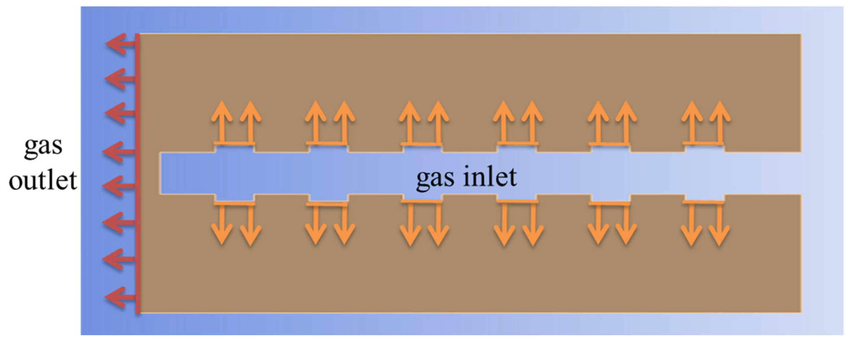
Figure 1. The scheme of improved combustor model. Orange arrows indicate the entry gas, and red arrows indicate the exit gas.
Energies 17 02153 g001
Figure 2. Grid unit size versus combustion temperature.
Energies 17 02153 g002
Figure 3. Comparison of combustion trends: (a) Combustion temperature at an initial velocity of 25 cm/s, (b) 35 cm/s, (c) 45 cm/s, and (d) 55 cm/s. The reference refers to the [12].
Energies 17 02153 g003
Figure 4. Influence of different operating conditions on combustion characteristics: (a) The highest temperature distribution under different working conditions, (b) a cloud map of temperature at equivalence ratio 0.65 and speed 70 cm/s.
Energies 17 02153 g004
Figure 5. Emission characteristics of ethylene combustion pollutants (a) CO and (b) NO emission at the outlet under different working conditions.
Energies 17 02153 g005
Figure 6. Effect of combustion aperture on combustion temperature: (a) Maximum temperature of the burner under different apertures, (b) Temperature cloud map with pore diameter of 35 mm, (c) 30 mm, (d) 25 mm, (e) 20 mm, and (f) 15 mm.
Energies 17 02153 g006
Figure 7. Effect of porosity on combustion temperature.
Energies 17 02153 g007
Table 1. Initial condition settings.
No.Equivalence RatioFlow Velocity (cm/s)
10.3045, 50, 55, 60, 65, 70
20.3530, 35, 40, 45, 50, 55, 60, 65, 70
30.4025, 30, 35, 40, 45, 50, 55, 60, 65, 70
40.4525, 30, 35, 40, 45, 50, 55, 60, 65, 70
50.5025, 30, 35, 40, 45, 50, 55, 60, 65, 70
60.5525, 30, 35, 40, 45, 50, 55, 60, 65, 70
70.625, 30, 35, 40, 45, 50, 55, 60, 65, 70
80.6525, 30, 35, 40, 45, 50, 55, 60, 65, 70
90.7025, 30, 35, 40, 45, 50, 55, 60, 65, 70
Disclaimer/Publisher’s Note: The statements, opinions and data contained in all publications are solely those of the individual author(s) and contributor(s) and not of MDPI and/or the editor(s). MDPI and/or the editor(s) disclaim responsibility for any injury to people or property resulting from any ideas, methods, instructions or products referred to in the content.