Article

Numerical Investigation on the Solar Absorption Performance of Plasmonic Nanoparticles in the Focused Electric Field

1
School of Energy and Power Engineering, North University of China, Taiyuan 030051, China
2
Institute of Electrical Engineering, Chinese Academy of Sciences, Beijing 100190, China
*
Author to whom correspondence should be addressed.
Energies 2024, 17(9), 2138; https://doi.org/10.3390/en17092138
Submission received: 23 March 2024 / Revised: 17 April 2024 / Accepted: 29 April 2024 / Published: 30 April 2024
(This article belongs to the Special Issue Advanced Solar Thermal Technology)

Abstract

:
Planar light concentrators are potential applications for solar thermal conversion, in which the intensity of the electric field will exhibit strongly non-uniform characteristics. However, previous research has long ignored the solar absorption performance of plasmonic nanoparticles in the focused electric field. In this work, we use the finite element method (FEM) to study the optical behaviors of a single nanoparticle and multiple nanoparticles in the focused electric field formed by vertically and inwardly imposing the initial incident light on a quarter cylindrical surface. The results show that the focused electric field can significantly improve the solar absorption abilities compared with the parallel one for all the nanoparticles due to the local near-electric field enhancement caused by the aggregation of the free electrons on the smaller zone. Further studies on the focused electric field reveal that the plasmon heating behavior of Au spheres presents a rising trend with the decrease in inter-particle spacing, as the gap is less than the radius of Au spheres. As the number of nanoparticles increases along the focal line, the absorption power of the center nanoparticles gradually tends to be stable, and it is much lower than that of a single nanoparticle. As the nanoparticles are arranged along the y and z directions, the heterogeneity of the electric field makes the optical properties uneven. Notably, the strongest electric field appears slightly close to the incident surface rather than on the focal line.

1. Introduction

Parabolic trough collectors are a mature solar concentration technology that produces high-temperature heat. However, parabolic trough collectors are encountering various issues in their operations [1,2,3,4,5,6], such as design and manufacture errors (e.g., no ideal reflected mirror surface) [1], the tracking mechanism usage and tracking system error [2], the effects of weather conditions on the installation stability (dusty, wind, rain, snow) [3], and the accuracy of the positioning sensor [4,5]. It should be highlighted that the problems mentioned above are directly linked to the costs of parabolic trough collectors [6].
To address the abovementioned issues, some researchers have proposed several approaches to concentrating sunlight by using planar focusing designs, such as planar waveguide concentrators [7,8,9,10,11], planar subwavelength grating concentrators [12,13], and planar metasurface-based concentrators [14,15,16,17,18,19]. In addition, they are more suitable for developing compact platforms than the curved lenses or mirrors used in concentrated solar power systems.
Planar waveguide concentrators with artificial micro-structures (injection and bypass elements [7], faceted micro-lens [8], focusing spherical lens [9], tapered cylindrical and conical lens [10], and square lenslet [11]) show tremendous promise for high optical efficiency, thin form-factor, lightweight, and inexpensive alternatives for the current generation of refractive and reflective solar concentrators. Planar subwavelength grating concentrators with unique diffraction properties have achieved a concentration ratio above 10× in medium-concentration solar systems [12]. The light intensity at the focal point and the reflectivity of the focusing grating mirrors are almost as high as those of parabolic mirrors. Planar-focusing grating mirrors offer a suitable replacement for parabolic mirrors, especially considering the complexity of fabricating three-dimensional structures compared to planar structures [13]. Optical meta-lenses, namely metasurface-based concentrators, exhibit great potential to achieve considerable angle and frequency dispersions on demand via strong coupling between building blocks and incident sunlight. Thus, they are also expected to replace traditional lenses and mirrors to efficiently capture broadband and wide-angle sunlight without tracking sun systems to generate cost-effective electricity by exploiting spatially distributed solar energy [14]. To design large-scale and highly efficient metasurface concentrators, some tactics are presented to elevate the robustness of metasurface concentrators. The rectangular parallelepipeds are less sensitive to fabrication imperfections than the ellipse and the cylinder [15]. The designs of a planar focusing collector (PFC) with a focal length beyond the micron scale are presented through metasurfaces and Fresnel-like models. The challenges of each design in the entire system process (design, fabrication, scalability, and techno-economic feasibility) are discussed. These works show how nano-optics and plasmonics could contribute to this vital area of concentrated solar power (CSP) technology [16,17,18,19].
Another critical challenge of solar thermal conversion is to improve the solar thermal collector design and the material’s performance for higher solar absorption [20,21]. The most common configuration of solar thermal collectors employs a black absorber surface, which transfers heat directly to a working fluid or via intermediate carrier liquids [22]. The surface absorber, unfortunately, has a large amount of heat loss and a low solar thermal conversion efficiency due to a significant temperature difference between the surface and the environment [23].
The direct absorption solar collector (DASC) is an alternative collector that absorbs solar radiation through the working fluid with excellent solar absorption efficiency. Particles at nanoscale dimensions have a large surface area-to-volume ratio, expose many active surface sites, and exhibit unique electronic properties (different from bulk) that improve solar absorption performance [24,25]. However, the advantages of size reduction are often overshadowed by the colloidal instability (extensive aggregation) of particles at the nanoscale, which can significantly reduce the solar absorption ability in the DASC [26,27,28].
Compared with the nanoparticles suspended in the working fluid, the ones fixed into the porous structure could effectively overcome the aggregation problems. Some assembled plasmonic gold nanoparticle thin films have been recently developed to improve the efficiency and stability of solar-enabled evaporation [29,30,31,32]. The air-laid paper is selected as the fixed substrate, inspired by biological evaporation systems such as human skin and plant leaves [29]. These gold nanoparticles deposited on the air-laid paper are fabricated more compactly than the free-standing plasmonic structure, which enables the fixed gold nanoparticles to exhibit much higher light absorption efficiency (more than 80%) in the solar spectrum of 400–800 nm and to yield the photo-thermal transformation efficiency of 77.8% under the 4.5 suns. A broadband and efficient aluminum-based plasmonic absorber is also proposed through the self-assembly of the aluminum nanoparticles into a 3D porous membrane, which demonstrates an extraordinary solar absorption of over 96% due to the reduced surface reflection and increased internal light scattering caused by the close-packed aluminum nanoparticles and the nanoporous structures [30,31]. A novel type of plasmonic material is made by uniformly decorating fine metal nanoparticles into the 3D mesoporous matrix of natural wood (plasmonic wood), which exhibits high light absorption ability (≈99%) over a broad wavelength range from 200 to 2500 nm due to the plasmonic effect of metal nanoparticles and the waveguide effect of microchannels in the wood matrix [32].
It is critical to develop and study a new solar absorption method that matches the planar light concentrators to apply the planar light concentrators to the solar thermal conversion field. In this work, the plasmonic nanoparticles are fixed near the focal line of the planar solar concentrator, and the heat-absorbing fluid flows around the plasmonic nanoparticles, in which the nanoparticles act as stationary internal heat sources, as seen in Figure 1. The optical properties of nanoparticles under the focusing electric field were calculated and discussed. We first compared the optical characteristics of a single plasmonic nanoparticle in the parallel electric field with those in the focused one. The focused electric field can achieve higher absorption performances in the same spectrum. Then, the absorption performances of the multi-nanoparticles system are studied in the focused electric field to understand the interactions of light with matter for the planar light concentrators.

2. Materials and Methods

Electric field propagation around the plasmonic nanoparticles can be described by the Helmholtz equation [33], which is solved by the finite element method (FEM):
× μ r 1 × E k 0 2 ε r E = 0
where E is the electric field of the medium, μ r is the relative magnetic permeability, k 0 is the wavenumber in space, ε r is the relative permittivity, which is expressed as ε r = n i k 2 , and n and k are the real and imaginary parts of the complex refractive index. The dielectric environment was chosen as 1.0 for the air, and the optical constant of gold (Au) came from Johnson’s results [34].
The total absorption power density of nanoparticle can be written as follows [35]:
Q h ,   a b s = λ 1 λ 2 Q h ,   a b s λ
Q h ,   a b s λ = 1 2 ε 0 ω ε E 2
where Q h ,   a b s is the total absorption power density, Q h ,   a b s λ is the absorption power density at various wavelengths, ε 0 is vacuum permittivity, ω is the frequency of the incident light, and ε is the imaginary part of material permittivity.
The total absorption, scattering, and extinction power can be obtained from the following functions [36,37]:
P a b s / s c a / e x t = λ 1 λ 2 P a b s / s c a / e x t λ
P a b s λ = Q h ,   a b s λ d V
P s c a λ = 1 2 R e E s c a × H s c a n d S
P e x t λ = P a b s λ + P s c a λ
where P a b s , P s c a , and P e x t are the total absorption, scattering, and extinction power, P a b s λ , P s c a λ , and P e x t λ are the absorption, scattering, and extinction power at various wavelengths, V is the volume, and S is the closed surface area, respectively.
During broadband solar spectrum, the total absorption, scattering, and extinction cross-section of nanoparticles can be calculated by the following:
C a b s / s c a / e x t = λ 1 λ 2 C a b s / s c a / e x t λ
C a b s / s c a / e x t λ = P a b s / s c a / e x t λ I λ
where C a b s , C s c a , and C e x t are the total solar absorption, scattering, and extinction cross-section, C a b s λ , C s c a λ , and C e x t λ are the solar absorption, scattering, and extinction cross-section at various wavelengths, and   I λ is the electric field intensity reaching the surface of the nanoparticle at various wavelengths.
The total solar absorption, scattering, and extinction coefficient can be obtained by the following:
ψ a b s / s c a / e x t = λ 1 λ 2 ψ a b s / s c a / e x t λ
ψ a b s / s c a / e x t λ = C a b s / s c a / e x t λ A
where ψ a b s , ψ s c a , and ψ e x t are the total solar absorption, scattering, and extinction coefficient of nanoparticles, ψ a b s λ , ψ s c a λ , and ψ e x t λ are the solar absorption, scattering, and extinction coefficients at various wavelengths, and A is the physical cross-sectional area of the nanoparticle.
The absorption ratio χ λ represents the ratio of absorption power to extinction power at various wavelengths, and the total absorption ratio χ is the sum of χ λ in a range from λ 1 to λ 2 :
χ λ = P a b s λ P e x t λ
χ = λ 1 λ 2 χ λ
In this work, the FEM software COMSOL Multiphysics 5.6 is employed to solve the Helmholtz equation. Firstly, the basic properties of each domain are defined. Secondly, the external and internal boundary conditions, including perfect matched layer (PML), scattering, and periodic boundary conditions, are strictly set. Then, the properties of the electromagnetic waves in the domain are set, including the incident electromagnetic wave type, incident direction, intensity, etc. Finally, the solve domains are meshed, and the electric field distribution can be calculated.
The plasmonic nanoparticles are placed along the focal line of the planar light concentrators, in which the electric field reached by the plasmonic nanoparticles is extraordinarily uneven. The solar heat performance of the focused and parallel incident light is expected to differ. Sunlight is unpolarized but can be broken down into two linearly polarized lights of equal intensity perpendicular to each other. The optical characteristics of nanoparticles are the added results of the incident electric field of E x and E y in the parallel electric field. At the same time, we can also calculate the optical properties by the superimposed E x and E y + E z in the focused electric field.
The absorption rate of Au nanoparticles is close to zero for the incident light wavelength of more than 900 nm. Thus, the wavelength is selected as 300–900 nm, the solar spectrum refers to ASTM G173-03 [38], and the total incident electric field intensity is I 0 = 683.65   W / m 2 . The incident light is perpendicularly exerted on a quarter cylindrical surface towards the central axis to form the focused electric field, where the cylinder radius is 1610 nm.
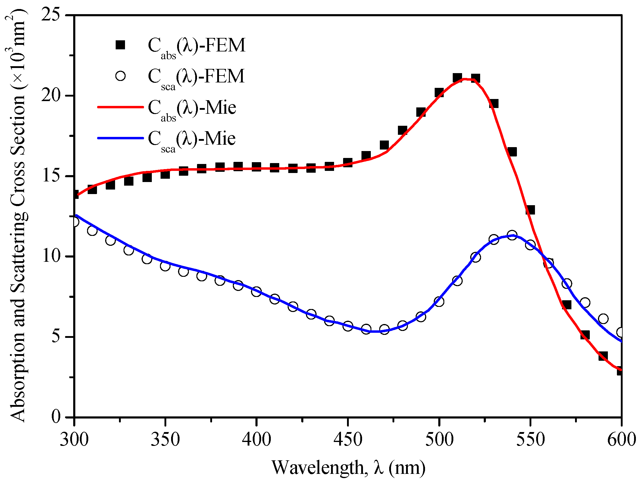
To verify the model, the absorption and scattering cross-sections of a single Au sphere with a diameter of 50 nm are compared between FEM and Mie theory calculation results in the parallel electric field of the visible light spectrum. Figure 2 shows that the maximum difference between the FEM calculation results and the Mie theory ones is less than 0.1%, indicating that the FEM calculation results are valid.

3. Results and Discussion

3.1. Optical Properties of a Single Plasmonic Nanoparticle in the Parallel and Focused Electric Fields

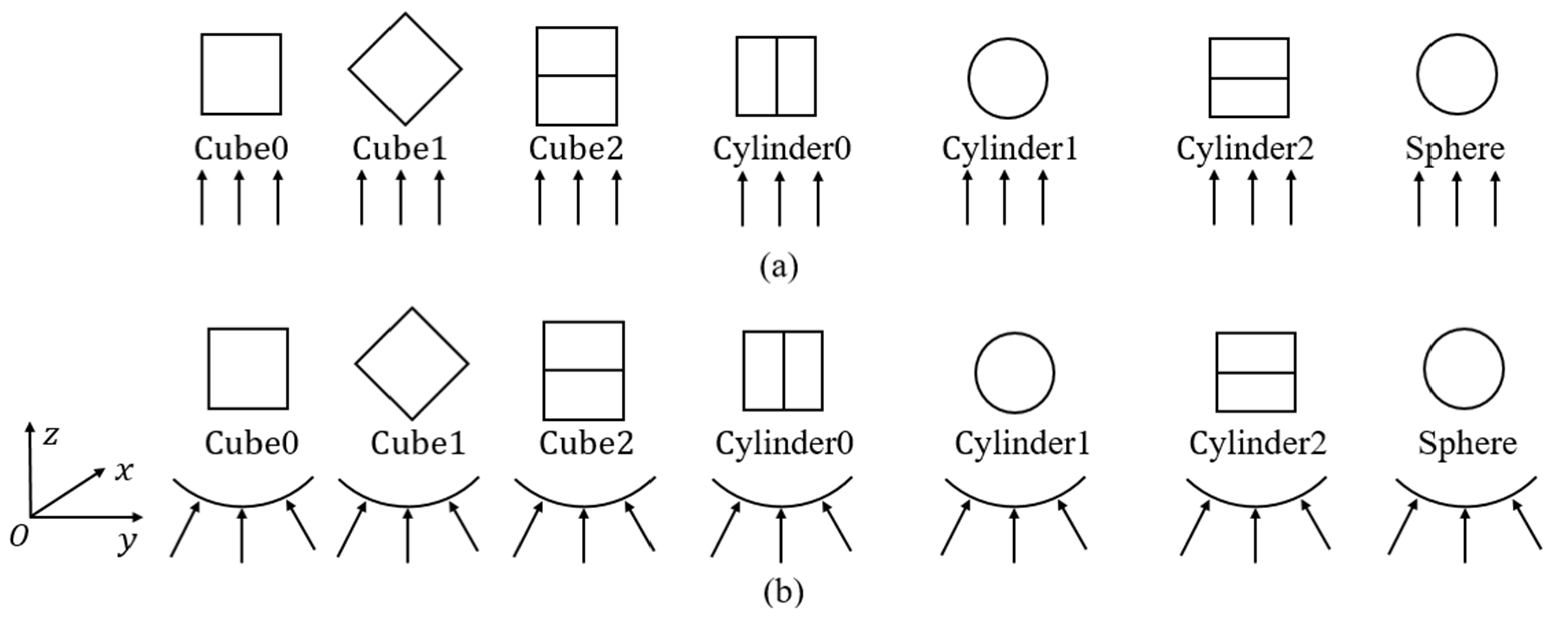
This section compares the optical properties of a single nanoparticle in the focused electric field with those in the parallel one. The absorption performances of the Au sphere are investigated at the radius (r) of 50 nm and the various r, where the schematics of the line-focusing electric field can be shown in Figure 3b. Then, we report the total optical properties of Au nanoparticles when their shapes and orientations change, but the feature sizes stay the same. Here, the shapes and orientations of nanoparticles can be set as in Table 1.
Table 1. Shapes and orientations of nanoparticles used in Section 3.1.
ShapesFeature LengthLabel I 0 (W/m2)Orientations
CubeThe length of the side is 100 nm.Cube 0683.65As seen in Figure 4
Cube 1
Cube 2
CylinderBoth the diameter and height are 100 nm.Cylinder 0
Cylinder 1
Cylinder 2
SphereThe diameter is 100 nm.Sphere
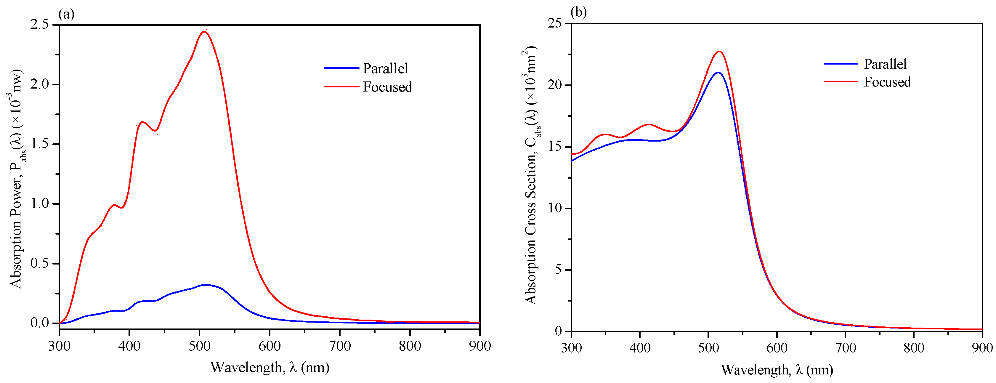
As shown in Figure 5, it is evident that the Au spheres achieve their prominent absorption peaks at 530 nm, whether placed in the parallel electric field or the focused one. The incident electric field coupled with the free electron oscillation around the nanoparticle surface at the resonance frequency can enormously enhance the absorption performance of the nanoparticle. Notably, there are several relatively minor resonance peaks in the spectrum of less than 500 nm for the focused electric field, which also leads to the broad and strong absorption ability. The physical cross-sectional area of a sphere is π r 2 in the parallel electric field, which is the spherical projection map on a plane. The one in the line-focused electric field in this work is the area of a quarter spherical surface projected on a cylindrical surface. Since a quarter spherical surface area equals π r 2 , its projection area on the cylindrical surface will become smaller. Therefore, the physical cross-sectional area of the Au sphere in the focused electric field is far smaller than that in the parallel one. However, the absorption cross-section in the focused electric field is higher than that in the parallel one, especially in the shorter wavelength region, which implies that the absorption coefficient ψ a b s λ will be even higher. This is attributed to the increasing electric field intensity imposed on a smaller local surface of nanoparticles in the focused electric field, in which the free electrons’ aggregation can enhance the local near-electric field. It indicates that the focused electric field significantly positively affects the local surface plasmon resonance (LSPR). The more substantial LSPR effect will produce the more resistive heat around the nanoparticle in the focused electric field.
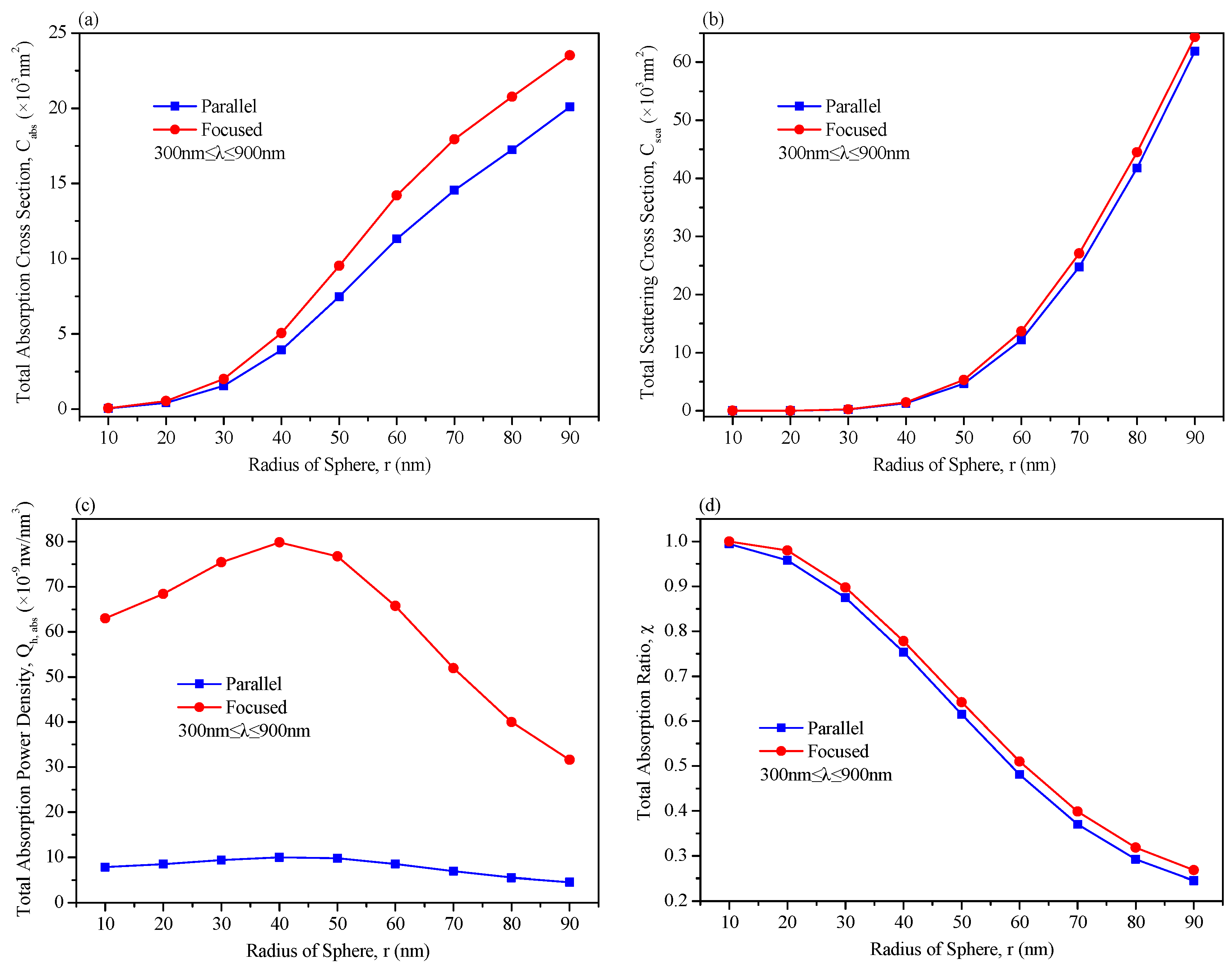
Figure 6a,b show that the total absorption and scattering cross-sections sharply rise with the growing sphere radius due to the larger physical cross-sectional area. In the meantime, the absorption cross-section in the focused electric field exceeds that in the parallel one at the increasing r , as shown in Figure 6a. The slopes in Figure 6a reveal that the absorption coefficient in the focused electric field declines slightly slower than that in the parallel one as r enlarges but not beyond 90 nm. From Figure 6c, it can be seen that the total absorption power density first increases and then decreases with the increasing radius of the Au sphere, and the peak takes place around the radius of 40 nm in both electric fields. The larger nanoparticle size weakens the absorptive action and heightens the scattering ability. In addition, the total absorption ratio χ presents a declining trend with the increasing sphere size, as displayed in Figure 6d. It demonstrates that the smaller nanoparticles are more suitable for solar thermal utilization, while the larger ones are for photovoltaic conversion to resist high temperatures. Meanwhile, the total absorption ratio is higher in the focused electric field than that in the parallel one, and the difference of χ between the two electric fields slightly rises at the larger size, as shown in Figure 6d.
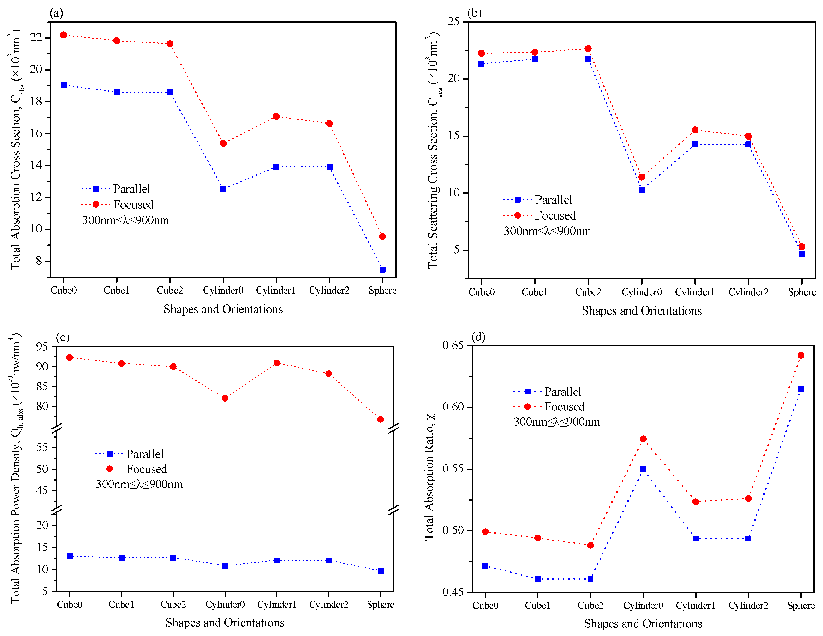
In Figure 7, the optical properties of all the nanoparticles tend to be improved dramatically in the focused electric field compared with the parallel one. Figure 7a,b show that the cubical nanoparticle’s total absorption and scattering cross-sections are highest in the focused and parallel electric fields. In contrast, the ones of spherical nanoparticles are the lowest. On the one hand, it is because the cubical nanoparticles have the most significant volume, and the spherical ones have the smallest volume. Another reason is that the cubical nanoparticles have the slightest sphericity, while the spherical nanoparticles’ sphericity is the largest. The more minor sphericity can result in higher optical performance, as the plasmonic nanoparticle absorbs the electromagnetic waves. Although the volume of the cubical nanoparticle is more prominent than that of the other two shapes, the cubical nanoparticle’s total absorption power density is slightly higher overall, as seen in Figure 7c. It confirms that the nanoparticle’s sphericity greatly influences the solar absorption performance. Figure 7d presents that the total absorption ratio of the Au sphere is the highest, while that of the nanoparticle in the cube 2 orientation is the lowest. It suggests that the selection of shapes and orientations is the competition between absorption ability and absorption ratio. For all the nanoparticles with the same shape, their orientations play significant roles in their LSPR effects, which depend on the included angle between the electric field direction and the surface normal vector of a nanoparticle. Moreover, the nanoparticles’ orientations in the focused electric field have fantastic effects on the optical properties since the optical anisotropism is more remarkable due to the highly non-uniform electric field.

3.2. Optical Properties of Multi-Plasmonic Nanoparticles in the Focused Electric Field

In this section, the optical properties of all the nanoparticles are simulated in the focused electric field, where the Au spheres’ radius remains r = 50   n m . Firstly, the effects of the distance between two Au spheres on their optical characteristics are investigated, and the schematic of two Au spheres in the focused electric field is described in Figure 8a. Secondly, the total absorption power and cross-section of Au sphere chains are studied, in which the inter-particle spacing is 10 nm. The schematics of nanoparticle chains along different coordinate axes are displayed in Figure 8b–d.
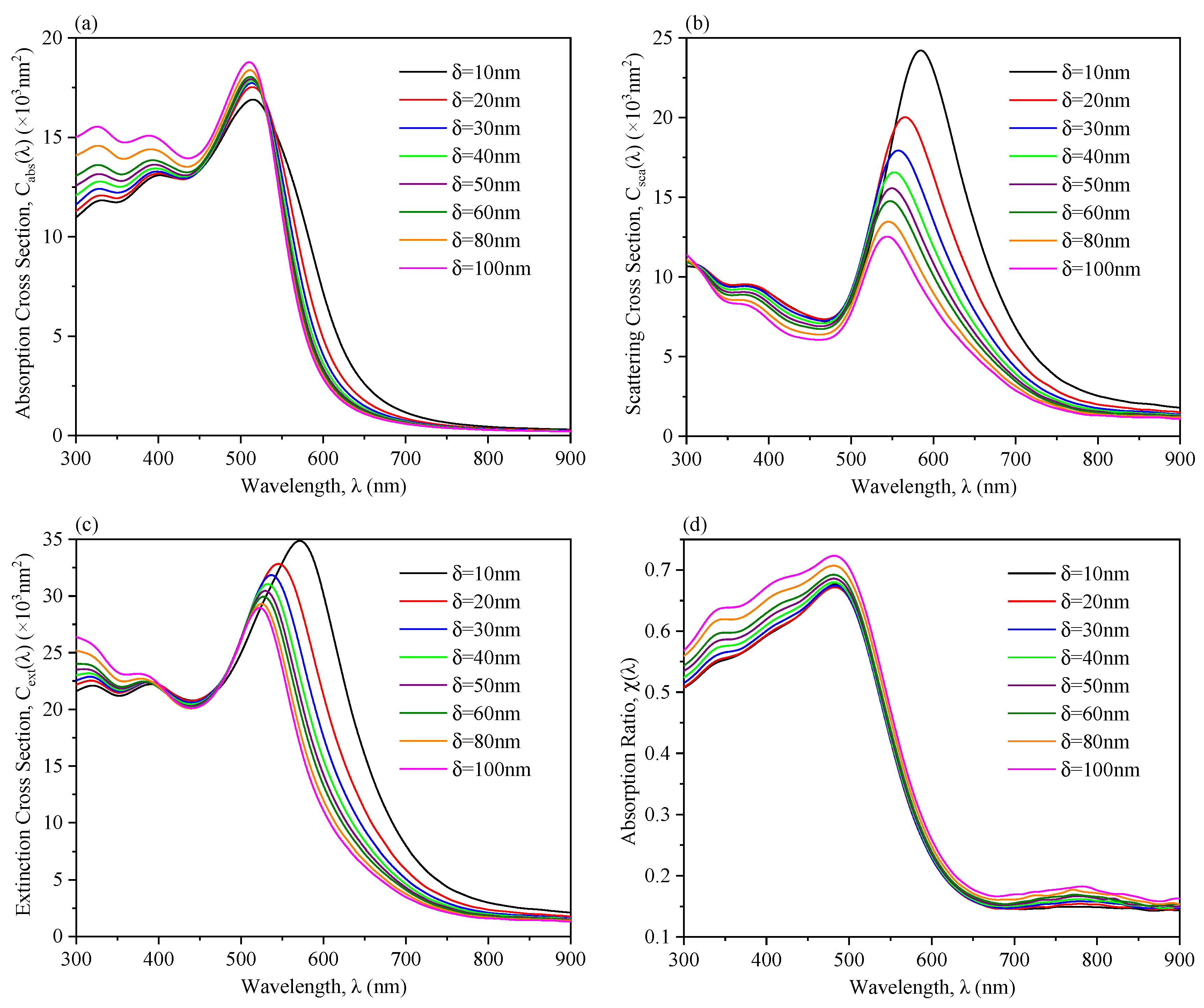
The peaks of C a b s λ , C s c a λ , and C e x t λ show blue shifts, a movement towards the short wavelength, with the increasing inter-particle spacing in Figure 9a–c. Regardless of the electron tunneling effect, it indicates that the nanoparticles absorb more energy with the reduced inter-particle gap due to the enhanced electric-field coupling, which is eventually translated into heat energy. The peak values of C s c a λ and C e x t λ present declining trends and one of the C a b s λ rises as the spacing enlarges. However, the enhancement amplitude of C a b s λ is smaller than the weakening amplitude of C s c a λ , as compared to Figure 9a with Figure 9b. The reason is that the incident electric field of E x can trigger the resonance enhancement effect, and E y + E z can restrain the internal electric field in the particle pair. Still, the enhancing effect is rather more than the restraining effect. It is also found that the resonance peak of each particle is lower in the particle pair model than the one in the single particle model. In Figure 9a, C a b s λ is higher at the larger δ when the wavelength is less than 550 nm, while it presents a declining trend with the increasing δ in the spectrum of more than 550 nm. As the inter-particle spacing grows, C s c a λ continuously decreases in the spectrum from 300 nm to 900 nm, as seen in Figure 9b. From Figure 9d, the more considerable inter-particle distance can lead to a higher absorption ratio in the spectrum from 300 nm to 900 nm.
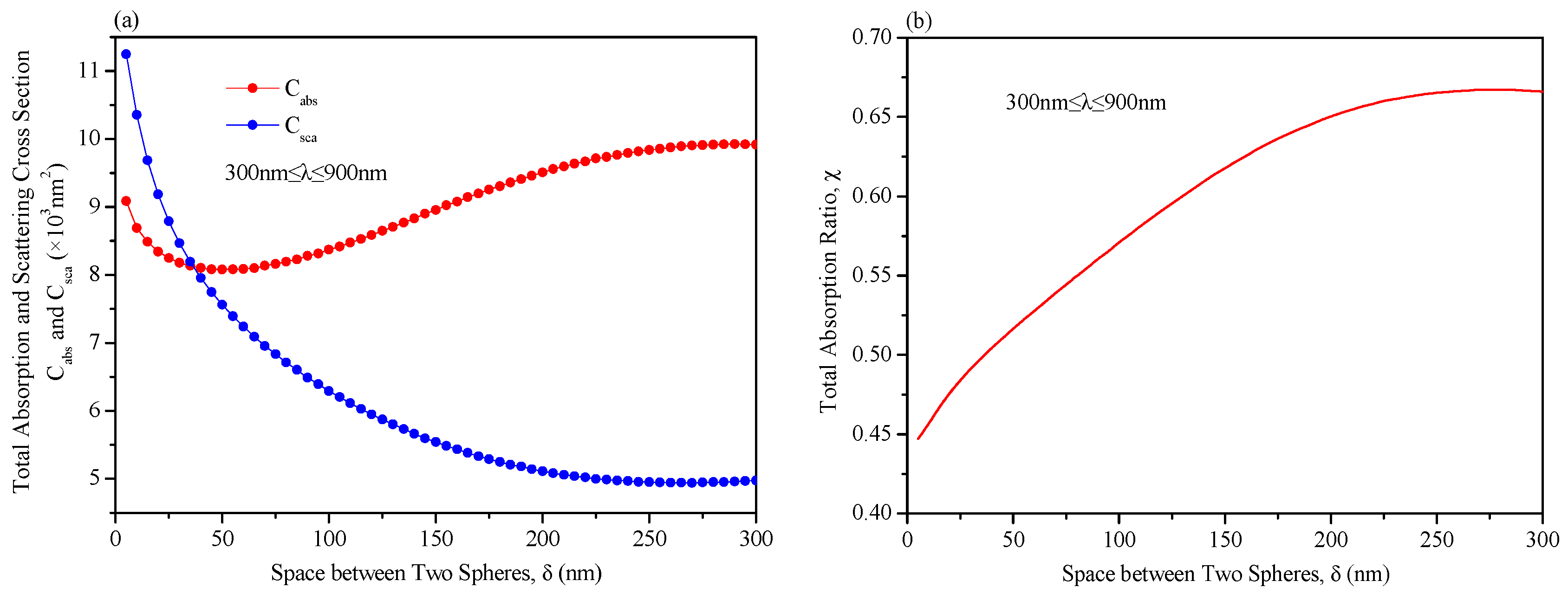
In Figure 10, as the inter-particle distance enlarges, the total absorption cross-section first decreases and then increases, the total scattering cross-section gradually declines, and the total absorption ratio presents a rising tendency. However, they all tend to be the values of a single Au sphere in the end when the inter-particle distance is far enough, comparing C a b s , C s c a , and χ in Figure 10 with those at the radius of 50 nm in Figure 6. This is because C a b s is mainly determined by the competition between the sum of C a b s λ in the spectrum from 300 nm to 550 nm and that in the wavelength of 550 nm–900 nm based on Equation (8). As the inter-particle distance is less than the Au sphere radius, C a b s is dominated by the sum of C a b s λ in the spectrum of more than 550 nm. In the meantime, as the inter-particle distance is more than the Au sphere radius, C a b s in the spectrum of less than 550 nm plays the dominant role. Since C s c a λ is lowering with the increasing inter-particle distance in the wavelength range from 300 nm to 900 nm, C s c a is gradually declining. To keep the higher absorption cross-section, the inter-particle gap should deviate from their radius as much as possible for the particle pair. Further, the smaller inter-particle distance is predicted to be better.
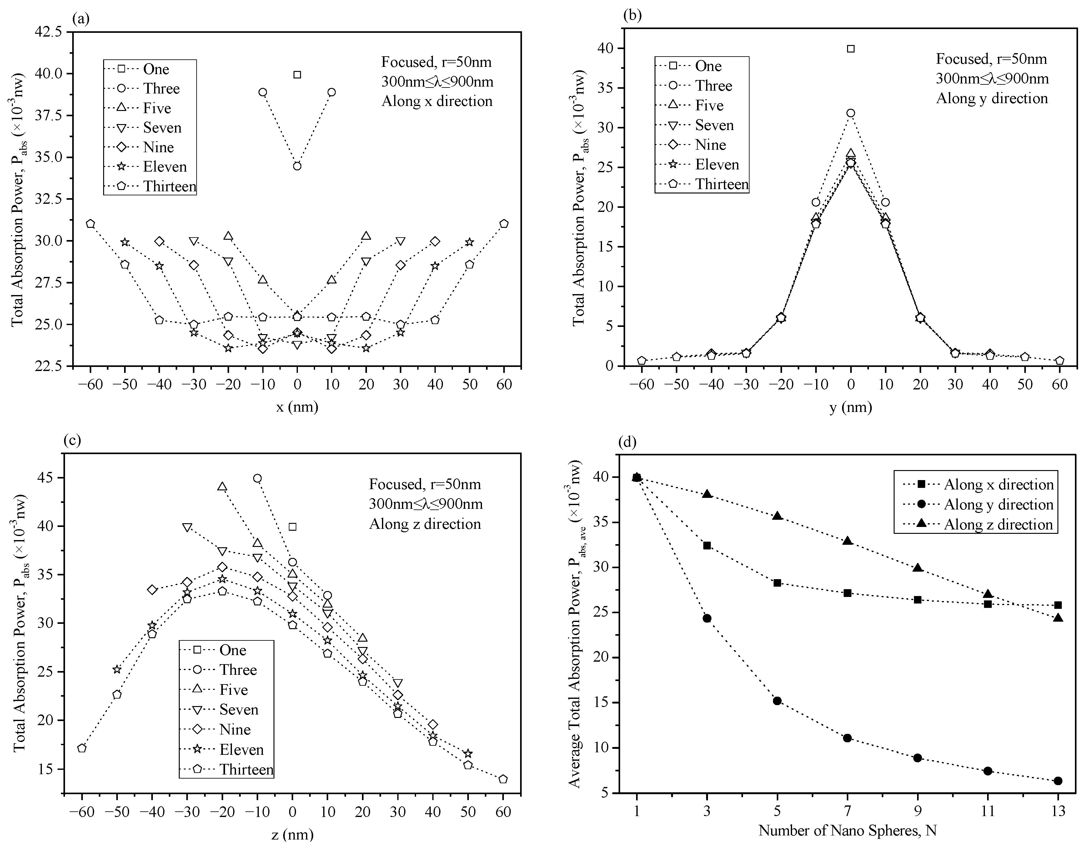
As shown in Figure 11a, the absorption performances of the middle Au spheres are lower than those at both ends when the number of nanoparticles increases due to the higher scattering enhancement among the middle nanoparticles. However, the absorption power keeps a rapidly declining tendency from the middle to both ends, and it finally goes to zero with more and more nanoparticles in Figure 11b. As the Au spheres are arranged along the y direction, the electric field intensity is higher at the position closer to the focal line. Thereby, the middle nanoparticles can absorb more solar energy. Meanwhile, Figure 11c illustrates that the most extensive P a b s occurs near the incident surface rather than on the focal line as the number of nanoparticles increases along the z direction. It indicates that the nanoparticles should not be placed on the focal line but slightly close to the incident surface since the most vigorous electric field intensity is not on the focal line in this case. Furthermore, for all the arrangement types of nanoparticles, more Au spheres can cause lower P a b s , a v e , and, eventually, it tends to be stable, as shown in Figure 11d.

4. Conclusions

In this work, the optical properties of the Au nanoparticles were studied based on the finite element method (FEM) to explore the solar absorption performance in the focused electric field. The effects of the nanoparticle size, shape, orientation, inter-particle gap, and arrangement style on the plasmon absorption characteristics were systematically analyzed. It was found that there are more improvable optical performances in the focused electric field than those in the parallel one, no matter what the nanoparticles are. It is attributed to the stronger electric field in the smaller area, compared with the parallel electric field. As the nanoparticle radius increases, the cross-section of absorption and the active range of electric radiation effectively increases. Thus, more light energy can be absorbed and converted into heat. Significantly, the lower the degree of sphericity is, the more the optical performance is enhanced. Increasing the inter-particle distance of the spherical nanoparticle pair can lead to the blue shifts for the absorption cross-section, implying that the heat production of nanoparticles gradually increases with decreasing inter-particle spacing. Each of the multi-spherical nanoparticles shows a lower absorption ability than a single one, and the average absorption performance of the nanoparticle chains tends to be stable with an increasing number of nanoparticles. The non-uniform solar absorption properties induced by the focused electric field are more prominent along the y and z directions. In particular, we found that the most considerable absorption power does not take place on the focal line but is a bit close to the incident surface.

Author Contributions

Methodology, X.Z. (Xueqing Zhang), F.B. and X.Z. (Xuesong Zhang); writing—original draft preparation, X.Z. (Xueqing Zhang); writing—review and editing, T.W., F.B. and Z.W.; supervision, F.B. and Z.W. All authors have read and agreed to the published version of the manuscript.

Funding

This work was financially supported by the National Natural Science Foundation of China (Grant No. 52106063) and the National Key Research and Development Program of China (Grant No. 2020YFA0710100).

Data Availability Statement

All data in support of the findings of this paper are available within the article.

Conflicts of Interest

The authors declare no conflicts of interest.

References

  1. Song, J.; Wang, W.; Niu, Y.; Wang, J.; Yu, H. A note of optical error diagnosis of parabolic trough concentrator based on flux image. Sol. Energy 2020, 197, 359–362. [Google Scholar] [CrossRef]
  2. Fend, T.; Wenzel, K. Optical flux measurements in the focal area of a parabolic trough concentrator. J. Phys. IV 1999, 9, 605–609. [Google Scholar] [CrossRef]
  3. Gharat, P.V.; Bhalekar, S.S.; Dalvi, V.H.; Panse, S.V.; Deshmukh, S.P.; Joshi, J.B. Chronological development of innovations in reflector systems of parabolic trough solar collector (PTC)—A review, Renew. Sustain. Energy Rev. 2021, 145, 111002. [Google Scholar] [CrossRef]
  4. Sallaberry, F.; Pujol-Nadal, R.; Perers, B. Optical losses due to tracking Misalignment on linear concentrating solar thermal collectors. In Proceedings of the Euro Sun 2016, Palma de Mallorca, Spain, 11–14 October 2016; International Solar Energy Society: Freiburg, Germany, 2016; pp. 1–12. [Google Scholar]
  5. Sallaberry, F.; Pujol-Nadal, R.; Larcher, M.; Rittmann-Frank, M.H. Direct tracking error characterization on a single-axis solar tracker. Energy Convers. Manag. 2015, 105, 1281–1290. [Google Scholar] [CrossRef]
  6. Stanek, B.; Wecel, D.; Bartela, L.; Rulik, S. Solar tracker error impact on linear absorbers efficiency in parabolic trough collector-Optical and thermodynamic study. Renew. Energy 2022, 196, 598–609. [Google Scholar] [CrossRef]
  7. Unger, B.L.; Schmidt, G.R.; Moore, D.T. Dimpled Planar Lightguide Solar Concentrators. In Proceedings of the International Optical Design Conference (IODC) and Optical Fabrication and Testing (OF&T), Jackson Hole, WY, USA, 13–17 June 2010; Optical Society of America: Washington, DC, USA, 2010; p. ITuE5P. [Google Scholar]
  8. Karp, J.H.; Tremblay, E.J.; Hallas, J.M.; Ford, J.E. Orthogonal and secondary concentration in planar micro-optic solar collectors. Opt. Express 2011, 19, A673–A685. [Google Scholar] [CrossRef]
  9. Svanbaev, E.; Mukhametkali, B.; Komesh, T.; Bekbolatov, Y.; Omirgali, A. Planar multicollector solar concentrator. In Proceedings of the International Conference on Natural Resource Management: Mechanics, Energy, Environment, Al-Ain, Abu-Dhabi, United Arab Emirates, 24–27 February 2013; pp. 215–219. [Google Scholar]
  10. Rudnitsky, A.; Zaban, A.; Zalevsky, Z. Passive high ratio sunlight concentration configurations. J. Europ. Opt. Soc. Rap. Public. 2013, 8, 13033. [Google Scholar] [CrossRef]
  11. Pan, J.W.; Su, Y.C.; Lee, S.Y. Optimized planar micro-optic concentrator design. J. Opt. 2016, 18, 065901. [Google Scholar] [CrossRef]
  12. Pesala, B. Planar Solar Concentrators using Subwavelength Gratings. In Proceedings of the Frontiers in Optics (FiO) 2011 and Laser Science (LS) XXVII Technical Digest, Optical Society of America and American Physical Society, San Jose, CA, USA, 16–20 October 2011; p. FWZ3. [Google Scholar]
  13. Komar, P.; Gębski, M.; Czyszanowski, T.; Dems, M.; Wasiak, M. Planar focusing reflectors based on monolithic high contrast gratings: Design procedure and comparison with parabolic mirrors. Opt. Express 2020, 28, 38745–38761. [Google Scholar] [CrossRef]
  14. Zhang, C.; Zhan, Y.; Qiu, Y.; Xu, L.; Guan, J. Planar metasurface-based concentrators for solar energy harvest from theory to engineering. PhotoniX 2022, 3, 28. [Google Scholar] [CrossRef]
  15. Hsu, L.; Dupré, M.; Ndao, A.; Kanté, B. From parabolic-trough to metasurface-concentrator assessing focusing in the wave-optics limit. Opt. Lett. 2017, 42, 1520–1523. [Google Scholar] [CrossRef] [PubMed]
  16. Ding, Q.; Jacobs, K.; Choubal, A.; Mensing, G.; Zhang, Z.; Tirawat, R.; Zhu, G.; Wendelin, T.; Guo, L.J.; Ferreira, P.; et al. A Simple Planar Focusing Collector for Concentrated Solar Power Applications. In Proceedings of the Optics for Solar Energy: Light, Energy and the Environment (E2, P.V., SOLAR, SSL), Boulder, CO, USA, 6–9 November 2017; Optical Society of America: Washington, DC, USA, 2017; p. RM2C.3. [Google Scholar]
  17. Qing, D.; Aakash, C.; Kimani, T. Design of a Nanopatterned Long Focal-Length Planar Focusing collector for concentrated solar power. In Proceedings of the Society of Photo-Optical Instrumentation Engineers (SPIE) Conference Series: Photonic and Phononic Properties of Engineered Nanostructures VII, San Francisco, CA, USA, 20 February 2017; p. 10112. [Google Scholar]
  18. Ding, Q.; Barna, S.; Jacobs, K.; Choubal, A.; Mensing, G.; Zhang, Z.; Yamada, K.; Tirawat, R.; Kincaid, N.; Zhu, G.; et al. A Metasurface-inspired Focusing Collector for Concentrated Solar Power Applications. In Proceedings of the OSA Frontiers in Optics/Laser Science, Washington, DC, USA, 20 September 2018; p. JTu3A.14. [Google Scholar]
  19. Ding, Q.; Barna, S.F.; Jacobs, K.; Choubal, A.; Mensing, G.; Zhang, Z.; Yamada, K.; Kincaid, N.; Zhu, G.; Tirawat, R.; et al. Feasibility Analysis of Nanostructured Planar Focusing Collectors for Concentrating Solar Power Applications. ACS Appl. Energy Mater. 2018, 1, 6927–6935. [Google Scholar] [CrossRef]
  20. Kalogirou, S.A. Solar thermal collectors and applications. Prog. Energy Combust. Sci. 2004, 30, 231–295. [Google Scholar] [CrossRef]
  21. Raj, P.; Subudhi, S. A review of studies using nanofluids in flat-plate and direct absorption solar collectors, Renew. Sustain. Energy Rev. 2018, 84, 54–74. [Google Scholar] [CrossRef]
  22. Minardi, J.E.; Chuang, H.N. Performance of a ‘‘black’’ liquid flat-plate solar collector. Sol. Energy 1975, 17, 179–183. [Google Scholar] [CrossRef]
  23. Chen, M.; He, Y.; Ye, Q. Solar thermal conversion and thermal energy storage of CuO/Paraffin phase change composites. Int. J. Heat Mass Tran. 2019, 130, 1133–1140. [Google Scholar] [CrossRef]
  24. Qin, C.; Kang, K.; Lee, I. Optimization of a direct absorption solar collector with blended plasmonic nanofluids. Sol. Energy 2017, 150, 512–520. [Google Scholar] [CrossRef]
  25. Wang, X.; He, Y.; Chen, M. ZnO-Au composite hierarchical particles dispersed oil-based nanofluids for direct absorption solar collectors. Sol. Energy Mater. Sol. Cells 2018, 179, 185–193. [Google Scholar] [CrossRef]
  26. Sezer, N.; Atieh, M.A.; Koc, M. A comprehensive review on synthesis, stability, thermophysical properties, and characterization of nanofluids. Powder Technol. 2019, 344, 404–431. [Google Scholar] [CrossRef]
  27. Rasamani, K.D. Composite Nanostructures as Effective Catalysts for Visible-Light-Driven Chemical Transformations. Ph.D. Thesis, Temple University, Philadelphia, PA, USA, 2020. [Google Scholar]
  28. Nakul, S.; Arunachala, U.C. Status, trends and significance of parabolic trough technology in the changing heat transportation scenario. Sol. Energy 2019, 187, 57–81. [Google Scholar] [CrossRef]
  29. Liu, Y.; Yu, S.; Feng, R.; Bernard, A.; Liu, Y.; Zhang, Y.; Duan, H.; Shang, W.; Tao, P.; Song, C.; et al. A Bioinspired, Reusable, Paper-Based System for High-Performance Large-Scale Evaporation. Adv. Mater. 2015, 27, 2768–2774. [Google Scholar] [CrossRef] [PubMed]
  30. Zhou, L.; Tan, Y.; Wang, J.; Xu, W.; Yuan, Y.; Cai, W.; Zhu, S.; Zhu, J. 3D self-assembly of aluminium nanoparticles for plasmon-enhanced solar desalination. Nat. Photonics 2016, 10, 393–399. [Google Scholar] [CrossRef]
  31. Zhou, L.; Zhuang, S.; He, C.; Tan, Y.; Wang, Z.; Zhu, J. Self-assembled spectrum selective plasmonic absorbers with tunable bandwidth for solar energy conversion. Nano Energy 2017, 32, 195–200. [Google Scholar] [CrossRef]
  32. Zhu, M.; Li, Y.; Chen, F.; Zhu, X.; Dai, J.; Li, Y.; Yang, Z.; Yan, X.; Song, J.; Wang, Y.; et al. Plasmonic Wood for High-Efficiency Solar Steam Generation. Adv. Energy Mater. 2018, 8, 1701028. [Google Scholar] [CrossRef]
  33. Zhao, J.; Pinchuk, A.O.; Mcmahon, J.M.; Li, S.; Ausman, L.K.; Atkinson, A.L.; Schatz, G.C. Methods for Describing the Electric Properties of Silver and Gold Nanoparticles. Chem. Soc. Rev. 2008, 41, 1710–1720. [Google Scholar]
  34. Johnson, P.; Christy, R. Optical constants of transition metals: Ti, V, Cr, Mn, Fe Co, Ni, and Pd. Phys. Rev. B. 1974, 9, 5056–5070. [Google Scholar] [CrossRef]
  35. Loudon, R. The propagation of electric energy through an absorbing dielectric. J. Phys. A Proc. Phys. Soc. Gen. 1970, 3, 233–245. [Google Scholar] [CrossRef]
  36. Liao, J.; Zhang, Y.; Yu, W. Linear aggregation of gold nanoparticles in ethanol. Colloids Surf. A Physicochem. Eng. Asp. 2003, 223, 177–183. [Google Scholar] [CrossRef]
  37. Moerloose, J.; Zutter, D. Poynting’s theorem for the finite difference time domain method. Microw Opt. Technol. Lett. 1995, 8, 257–260. [Google Scholar] [CrossRef]
  38. ASTM G173-03(2012); Standard Tables for Reference Solar Spectral Irradiances: Direct Normal and Hemispherical on 37° Tilted Surface. ASTM: West Conshohocken, PA, USA, 2012.
Figure 1. Schematic of the solar thermal collector with a planar light concentrator.
Energies 17 02138 g001
Figure 2. Comparison results between the FEM and Mie theory with the Au sphere (radius: 50 nm) in air.
Energies 17 02138 g002
Figure 3. Schematics of a single plasmonic Au sphere in the electric field: (a) parallel and (b) focused.
Energies 17 02138 g003
Figure 4. Shapes and orientations of nanoparticles used in Section 3.1: (a) in the parallel electric field and (b) in the focused electric field.
Energies 17 02138 g004
Figure 5. Optical properties of Au sphere in the parallel and focused electric fields: (a) P a b s λ and (b) C a b s λ .
Energies 17 02138 g005
Figure 6. Optical properties of Au sphere at various radiuses in the parallel and focused electric fields: (a)   C a b s , (b) C s c a , (c) Q h ,   a b s , and (d) χ .
Energies 17 02138 g006
Figure 7. Optical properties of Au nanoparticles with different shapes and orientations in the parallel and focused electric fields: (a) C a b s , (b) C s c a , (c) Q h ,   a b s , and (d) χ .
Energies 17 02138 g007
Figure 8. Schematics of multiple Au spheres in the focused electric field: (a) Au sphere pair, (b) Au sphere chain along the x direction, (c) Au sphere chain along the y direction, and (d) Au sphere chain along the z direction.
Energies 17 02138 g008
Figure 9. Optical properties of each sphere in the sphere pair at various wavelengths for the focused electric field: (a) C a b s λ , (b) C s c a λ , (c) C e x t λ , and (d) χ λ .
Energies 17 02138 g009
Figure 10. Optical properties of each sphere between the sphere pair at various inter-particle spacings for the focused electric field: (a) C a b s and C s c a , and (b) χ .
Energies 17 02138 g010
Figure 11. Absorption performances of Au sphere chains along different coordinate axes in the focused electric field: (a) P a b s along the x direction, (b) P a b s along the y direction, (c) P a b s along the z direction, and (d) P a b s ,   a v e .
Energies 17 02138 g011
Disclaimer/Publisher’s Note: The statements, opinions and data contained in all publications are solely those of the individual author(s) and contributor(s) and not of MDPI and/or the editor(s). MDPI and/or the editor(s) disclaim responsibility for any injury to people or property resulting from any ideas, methods, instructions or products referred to in the content.