1. Introduction
Energy plays a crucial role in residents’ daily life and production. With rapid economic development, the consumption of traditional fossil fuels such as oil and coal continue to increase. However, as these traditional fossil fuels are non-renewable, it leads to a persistent strain on the energy supply. Additionally, there are issues of low energy efficiency, an irrational energy usage structure, and environmental issues [
1]. Countries worldwide recognize carbon neutrality as a necessary solution. For instance, China has set the goal of reaching a peak in carbon emissions by 2030 and achieving carbon neutrality by 2060 [
2]. Global nations are actively taking measures to combat climate change and reduce greenhouse gas emissions, pursuing low-carbon development goals. The signing of the Paris Agreement symbolizes the international community’s joint commitment and action to address climate change [
3]. For instance, France, a significant member of Europe, has set an ambitious goal to achieve near-zero emissions by 2050. The realization of this goal will primarily depend on the development and utilization of renewable energy sources to decrease reliance on fossil fuels, thereby reducing carbon emissions. In order to reduce carbon emissions, the U.S. government provides financial incentives for the implementation of carbon capture and storage technology.
The electricity industry, characterized by the high consumption of fossil fuels and significant carbon dioxide emissions, is crucial for advancing low-carbon development. To enhance energy efficiency and reduce consumption, there is an urgent need to integrate different energy sources actively. This can be accomplished by improving the capacity for new energy absorption, utilizing renewable energy sources to partially replace conventional electricity, thus decreasing reliance on natural gas or coal power. Moreover, implementing waste-heat recovery systems for the exhaust gases from gas turbines can effectively replace some of the externally sourced heat or reduce the thermal energy consumption of gas boilers. Actively utilizing renewable energy sources becomes a key strategy for addressing these challenges. However, traditional energy systems lack flexibility, and the variability and randomness of solar and wind energy lead to suboptimal utilization rates. Coordinating between different energy sources has become a crucial approach to enhancing the absorption capacity of wind and solar energy. Integrated energy systems (IESs) represent a popular approach for achieving the coordinated integration of various energy sources [
4]. IESs transform the traditional forms of energy utilization and trading. They are systems that combine electricity, cooling, and the utilization of electricity and natural gas, facilitating the scheduling and planning of different energy sources [
5]. Also, they possess significant importance in promoting the clean and low-carbon goals of energy, as well as achieving the integration of source, grid, load, and storage [
6].
Coordinating the operational states of different devices in IES, enhancing system flexibility, strengthening the coupling capabilities of system devices, reducing energy costs, and minimizing carbon emissions are crucial research directions. Significant progress has been made in this field, with some noteworthy achievements that are highly worth considering. Gomes et al. [
7] established an optimization model for an independent microgrid in a remote area, determining the most cost-effective combination of renewable energy and energy storage technologies in the microgrid and subsequently obtaining the optimal configuration for the microgrid. For nearly zero-carbon emission communities, they have been introduced into regional IESs and have played a crucial role therein. Simultaneously, these community entities extensively and massively utilize renewable energy sources within the region, coordinating the utilization of their own combined heating and power (CHP) systems with those of surrounding IESs. Dimitriadis et al. [
8] proposed a coupled electricity and natural gas market model that includes a hybrid energy storage system and wind power generation. The model, by simulating the volatility of wind power generation, has demonstrated that such volatility can effectively increase the economic benefits of power systems equipped with energy storage technology. Through this market design, it is possible to achieve an optimized allocation of electricity and natural gas resources in the IES, enhancing its overall operational efficiency and economic performance. Moreover, these near-zero-emission communities exhibit characteristics of high renewable energy utilization levels and large-scale utilization [
9,
10]. Guo et al. [
11] introduced a net-zero-emission IES into a regional large-scale IES, establishing a dual-layer model for optimization. This model facilitates capacity configuration of devices within the region and optimizes operational scheduling regarding the daily operations of IESs on typical days. In current studies, nearly zero-carbon emission communities are often treated as energy supply units within a region and are not regarded as separate entities participating in the electric–carbon collaboration of other entities in IESs. However, for net-zero-carbon emission communities, determining their role in multi-entity collaboration within IESs is crucial.
Currently, most studies focus on the energy scheduling of a single IES. However, with the establishment of numerous IESs, there may be multiple independent IESs in the same region in the future, forming multi-park integrated energy systems (MIESs). An MIES is composed of multiple IESs that cooperate through electricity and heat networks for energy exchange [
12]. Traditional dispatch methods encounter challenges in supporting the energy transfer requirements between different IESs, thus necessitating the development of new dispatch methods. Bian et al. [
13] developed a model for MIESs. They innovatively introduced a method that uses controlled pricing to enhance electricity trading among various integrated energy systems within a microgrid. This approach not only meets the energy transfer needs of IESs but also takes into account and fulfills their respective trading preferences. Yan et al. [
14,
15] developed a joint scheduling model for multi-cold-hot-electricity supply-type micro-grids considering P2P transactions. This model prioritizes meeting the partial electricity shortfall of micro-grids through P2P transactions while absorbing surplus electricity within the system, improving energy utilization efficiency and making the trading strategy more economically efficient. The study found that when P2P transactions occur between microgrids, the scheduling strategy of micro-grids is relatively simple, and the output of the gas boiler is lower, making the overall scheduling more flexible. Chien et al. [
16] proposed the application scenario of tradable energy systems in the operation of community microgrids and established a model suitable for P2P transactions between microgrid users with distributed energy sources and storage. Microgrid users have the ability to trade with the grid on demand or surplus electricity in P2P markets and can choose to store excess electricity. Intelligent contracts are established at the market trading level, stored in the grid, and can be automatically executed. The research validated the effectiveness and efficiency of the proposed P2P trading mechanism.
In the context of reducing carbon emissions and carbon trading, the majority of IESs still adhere to traditional carbon trading mechanisms. Sun et al. [
17] introduced a tiered carbon trading mechanism into the IES, analyzed the impact of the tiered carbon trading mechanism on the IES and carbon emissions, and found that the carbon trading mechanism would promote the development of the IES towards low carbonization. Jin et al. [
18] introduced the carbon trading mechanism into IESs with wind power and derived its optimized scheduling model. They analyzed the influence of carbon trading formulation on economic efficiency and carbon emissions. While this model provides guidance for the low-carbon economic dispatch of IESs, it only considers traditional carbon trading scenarios. With the large-scale establishment of IESs, IESs require a new carbon trading model. Mao et al. [
19] have introduced an effective carbon management approach that allocates emission quotas based on an integrated energy system’s historical emissions. This strategy is flexible, permitting these systems to buy more quotas if needed or sell any surplus on the carbon market, optimizing resource use. Liu et al. [
20] incorporated the concept of green certificates into MIESs, establishing a cross-regional trading mechanism that facilitates the exchange of green certificates between IESs. This paper constructs a framework similar to the cross-regional carbon trading mechanisms proposed in the aforementioned literature, but with a distinct feature that permits the exchange of carbon quotas obtained by IESs to achieve optimal allocation. In order to further incentivize carbon quota trading between different IESs, this study recommends providing tax incentives for such transactions that are similar to subsidies for carbon capture and storage.
Table 1 illustrates a comprehensive comparison between the proposed approach and relevant literature contributions.
In summary, currently, most MIES studies focus on the electricity dispatch between IESs and ignore a electricity–carbon joint trading mechanism and how different IESs, through collaborative efforts, impact their carbon emission costs. Research on the potential for carbon collaboration is relatively limited. Additionally, the involvement of nearly zero-emission communities in carbon collaboration within MIESs has received insufficient attention. In collaborative scenarios, when an IES faces other demands such as heating or cooling loads, these can be addressed by purchasing electricity or dispatching power from another IES to reduce the costs of energy acquisition or carbon emissions. Therefore, this paper establishes a multi-agent IES optimal economic electricity–carbon joint dispatch model. The model optimizes system economics while considering carbon costs and strengthens inter-regional electricity exchanges. The main contributions of this paper are as follows.
- (1)
By introducing a near-zero emission community on a typical summer day as an independent entity into the MIES, this paper constructs a multi-agent community economic scheduling model that includes combined heat and power (CHP). The model enhances the coupling of electricity, natural gas, cooling, and heating, achieving multi-community multi-energy complementarity.
- (2)
An energy interaction strategy is proposed in this paper for the MIES, effectively balancing economic efficiency and low carbon emissions.
- (3)
The study takes advantage of the differences in carbon prices across regions to implement carbon quota sharing among all IESs, thereby reducing the overall carbon trading costs within the region. This method facilitates coordinated cooperation between different IESs to collectively address carbon emission issues.
- (4)
This paper suggests that to encourage the sharing of carbon quotas among IESs, incentives such as tax benefits could be provided to those IESs participating in the sharing. These incentives could then be integrated into the scheduling algorithms.
The organizational structure of this paper is as follows. Firstly, in
Section 2, the component model of the MIES and the electric–carbon co-optimization model for the MIES are introduced. Subsequently, in
Section 3, the paper describes the economic scheduling model for the MIES under the tiered carbon trading mechanism. In
Section 4, the paper conducts a case analysis of the system benefits under different operational modes and the economic benefits achieved through carbon co-optimization. Finally, in
Section 5, conclusions are drawn.
3. Electric–Carbon Joint Economic Scheduling Strategy for Multi-Park Integrated Energy Systems
Based on the MIES proposed in
Section 2, this section presents an electric–carbon joint scheduling strategy for the MIES. This strategy aims to effectively reduce the operational costs and carbon trading costs within the region while promoting collaboration between different systems. Within their respective IESs, the operational system architecture is applied based on
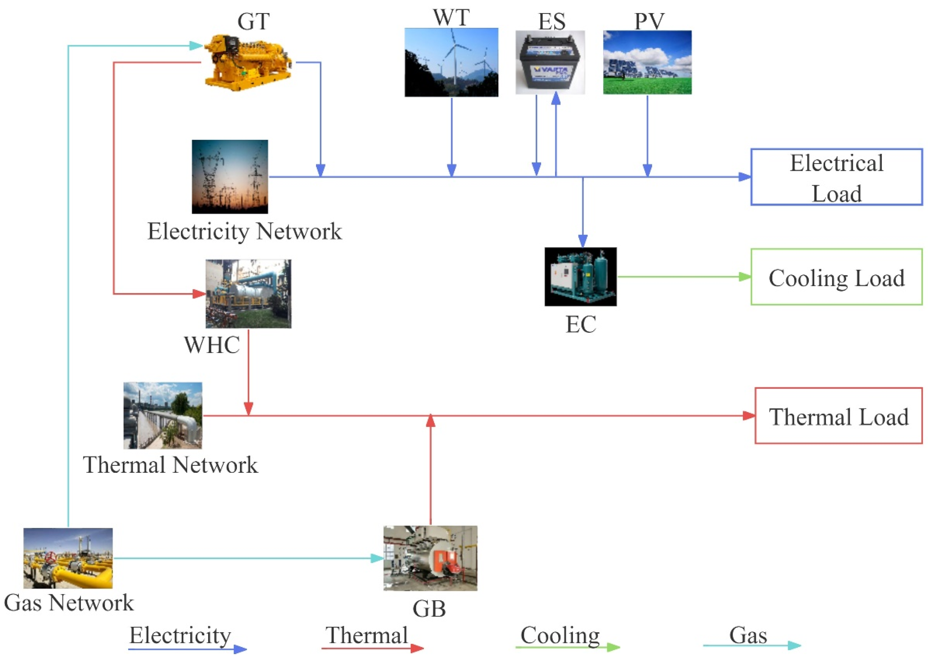
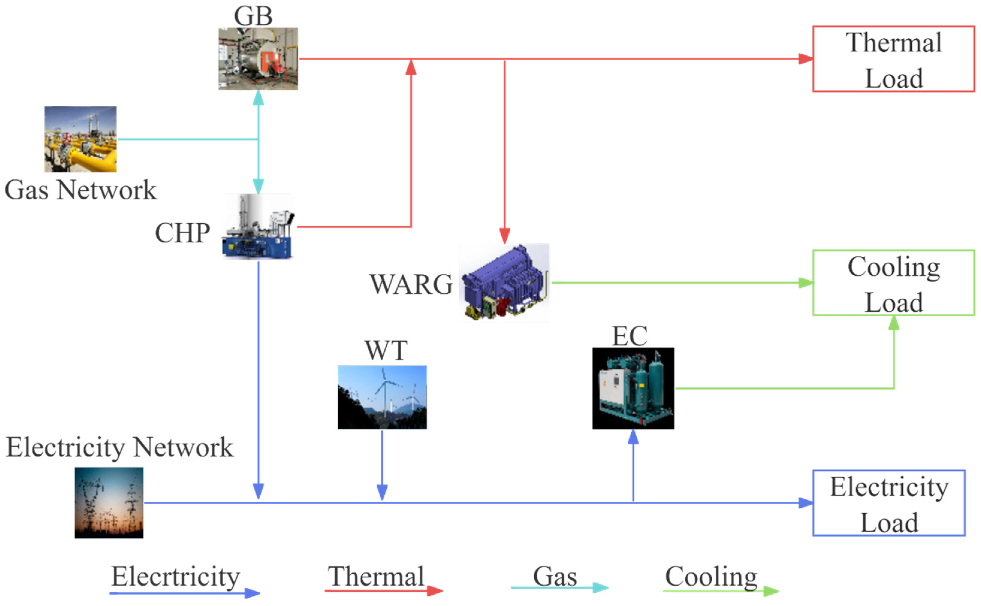
Figure 3,
Figure 4 and
Figure 5. The collaborative scheduling approach for different IESs utilizes the methods proposed in
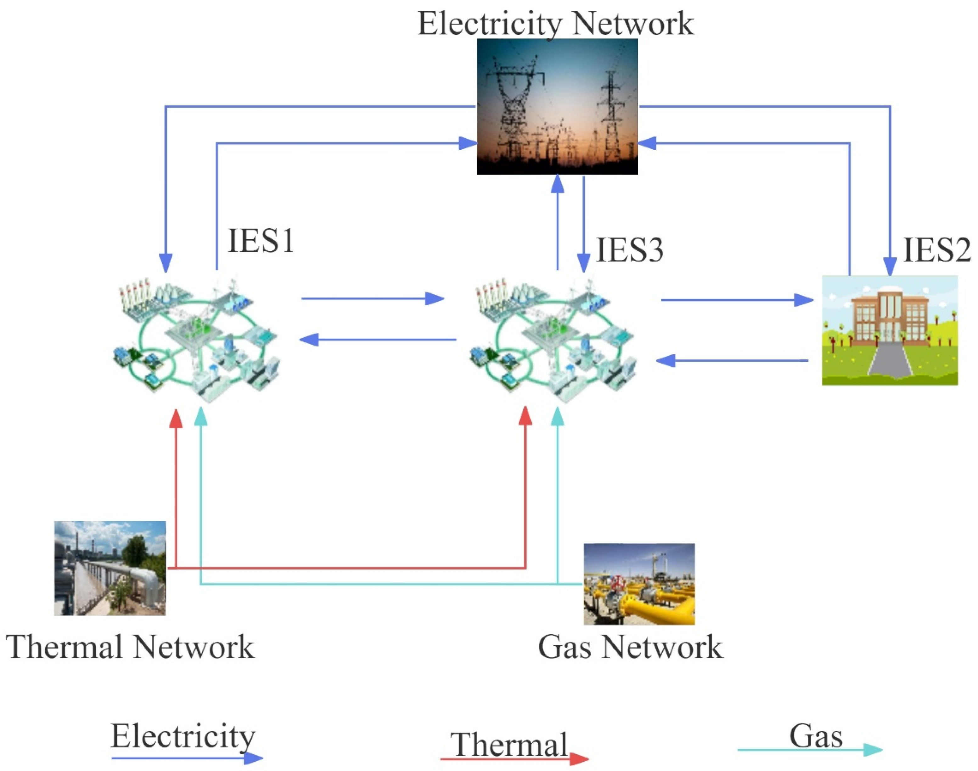
Figure 1 and
Figure 2. Under the ladder-type carbon trading mechanism, by fully utilizing the diverse energy conversion equipment within IESs and fostering carbon and electric coordination between systems, a framework for the electric–carbon joint scheduling model of the MIES is established. This model comprehensively considers the operational conditions both within and outside the region under the carbon trading mechanism. Through collaborative scheduling optimization, it enhances overall energy utilization efficiency and facilitates multi-energy complementarity between regions.
In
Section 3.1, within the electric–carbon joint economic scheduling strategy model, considering the diversity of IES within the region, the objective function integrates the diversity of IESs within the region, encompassing various cost factors such as carbon costs, energy costs, and others. This objective function, centered around both economic and environmental considerations, offers a comprehensive assessment of economic benefits for the system.
To meet the demands of different load types within the IES and ensure the normal operation of various devices, it is necessary to ensure that the operation of these devices complies with a set of constraints. These constraints are detailed in
Section 3.2. These constraints involve various aspects, including power, capacity, energy storage, mutual transmission between the grid and equipment, as well as inter-system IES interactions. They play a crucial role in ensuring the rational operation of the IES.
3.1. Problem Formulation
The objective of the economic scheduling model is to minimize the total cost of all IESs within the region while meeting the various load demands of the different IES within the region. The objective function is as follows.
where
is the cost of all IESs in the region,
is the cost of purchasing natural gas for all IESs in the region,
is the cost of purchasing thermal for all IES in the region,
is the cost of purchasing electricity for all IESs in the region,
is the revenue from selling electricity to the grid for all IESs in the region,
is the revenue from selling heat during the billing period for all IESs in the region, and
is the cost of carbon emissions in the region.
is the penalty cost for the incomplete absorption of wind and solar energy.
represents the quantity of carbon quota exchanged between IESs,
and
respectively denote the tax levied by the government on the trading of carbon quotas between integrated energy systems and the tax incentives provided by the government to encourage such trading activities.
- (1)
The natural gas procurement cost for the MIES
where
is the cost of natural gas per unit of power.
- (2)
The cost of buying heat for the MIES
where
represents the heat power purchased by IES
i, and
is the time-of-use thermal price per unit power.
- (3)
The cost of purchasing electricity for the MIES
where
is the time-of-use electricity price per unit power.
- (4)
The revenue from selling electricity for the MIES
where
is the time-of-use selling price of electricity per unit power.
- (5)
The revenue from selling thermal for the MIES
where
represents the heat power selling by IES
i, and
is the time-of-use selling of thermal per unit power.
- (6)
The penalty cost for the MIES
- (7)
The ladder-type carbon trading cost of the MIES
The ladder-type carbon trading mechanism promotes energy conservation and emission reduction through the commercialization of carbon emissions rights. This mechanism first addresses the issue of determining the gradient. Carbon emissions allowances are typically allocated for free. If an entity exceeds its allocated free quota, it needs to purchase the corresponding carbon emissions quota from external sources. However, as an MIES, it can transfer carbon allowance from other IESs. Unlike traditional carbon trading, the tiered carbon trading mechanism features a gradient design, dividing different intervals where the higher the required carbon emissions quota, the higher the corresponding interval price. For the region, the unit incorporating carbon pricing is based on the total emitted carbon from each IES within a given period. The carbon sources for IESs include carbon-containing natural gas and the electricity generated from coal, and the cost calculation formula is as follows.
where
and
represent the actual carbon emissions from electricity purchased by IES
i and the emission factor per unit of electrical power, respectively.
and
denote the carbon emissions from natural gas purchased by IES
i and the emission factor per unit of natural gas, respectively.
is the carbon emission cost for IES
i within a pricing period.
is the base price for carbon trading,
is the price growth rate, and l is the interval length for carbon emissions.
is the total carbon emission cost for all IESs within the region in a pricing period.
3.2. The Constraint for Multi-Park Integrated Energy Systems
The MIES constructed in this paper mainly consists of three types of loads: electrical, thermal, and cooling loads. Therefore, the internal constraints of the IES must ensure the balance of these three types of loads. Additionally, each individual IES should meet the power constraints, capacity constraints, energy storage power constraints, grid power constraints, and inter-system power transfer constraints for each device within the system.
3.2.1. Load Constraint
In
Section 3.2, a comprehensive examination of constraints will be presented. These constraints are formulated to secure the internal system equilibrium, fulfill the requirements of diverse load types, and ensure the seamless operation of diverse devices. Encompassing power, capacity, energy storage, interconnections among the grid and devices, as well as interactions between IESs, these constraints assume a pivotal role in fostering the effective functioning of the IES.
- (1)
Electricity load balance
Given that different IESs must maintain electrical load balance, achieving electrical load constraints becomes crucial. The expression for electrical load constraints not only covers the electrical energy required by the IES but also includes the means to ensure that the electrical load is reasonably satisfied. These constraint conditions are crucial for maintaining the stable operation of the system and meeting user demands. The expressions are as follows.
For an IES with CHP, wind turbines, and interaction with the electrical grid, the electrical load constraint model, along with cooperation with other IESs, is as follows.
- (2)
Thermal load constraint
The thermal load constraint is represented by the following expression.
where
represents the thermal load of IES
i at time
t.
represents the thermal power interaction of IES
i with the thermal network at time
t. At time
t, IES
i either purchases thermal energy from the thermal network or sells thermal energy to the thermal network; both cannot occur simultaneously. This is expressed as follows.
For the case where CHP provides heating and there is also water absorption refrigerator group for cooling, the thermal load constraint model is as follows.
- (3)
The cooling load constraint
The cooling load constraint is represented by the following expression.
For an IES with a water absorption refrigerator group, the cooling load constraint model is as follows.
where
represents the cooling load of IES
i at time
t.
where
represents the natural gas load of IES
i at time
t. For an IES with CHP, the natural gas load constraint is as follows.
3.2.2. Capacity and Operational Constraints
In the previous
Section 3.2.1, load constraints were discussed. However, for the normal operation of an IES, this is not sufficient. The IES must not only achieve load constraints but also meet a series of constraints related to the operation of internal devices. The combined implementation of these two aspects ensures the proper functioning of IES. The following provides a detailed explanation of the operational constraints of devices to further enhance the overall scheduling model.
These constraints contribute to maintaining the stability of the system, ensuring that each device operates within reliable ranges to meet actual operational demands. For the devices in the comprehensive energy system, there are not only operational constraints but also control constraints for each device in the system. The control constraints are as follows:
where
and
represent the ramping rate limits on the gas turbine and gas boiler, respectively, for IES
i. Due to the presence of an electric energy storage module within the IES, it is subject to power constraints during both charging and discharging processes. The specific expression is as follows.
where
represents the battery capacity of IES
i.
and
represent the binary (charge/discharge) power variables of IES
i. Equations (45) and (46) define the maximum output power and minimum input power for the electric energy storage system, ensuring its operation within a reasonable range. Equation (47) is a binary variable constraint that prevents the energy storage system from charging and discharging simultaneously. Due to the requirement that the energy state of the battery must be equal at the beginning and end of a complete scheduling cycle, it is expressed as follows:
3.2.3. Power Transmission Constraints
To ensure that different IESs in the region maintain a reasonable range in buying and selling electricity, as well as exchanging power between IES and the power grid, the power exchange with the power grid and the power transmission between IESs are subject to certain constraints. Specifically, these are expressed as follows:
4. Case Study
In the previous sections, the MIES and the electric–carbon joint scheduling strategy for the MIES were introduced. Building upon this foundation, this section validates the effectiveness of the approach through detailed simulations. In
Section 3.1, fundamental data were provided. In
Section 4.2, to verify the effectiveness of the proposed method, four scenarios were designed based on these fundamental data. An analysis of the costs in different scenarios was conducted, leading to the conclusion of the strategy’s effectiveness.
4.1. Simulation Setup
This paper selected three integrated energy demonstration zones in China as the research objects, focusing on the summer season. As this period coincides with the summer vacation in Chinese schools, IES2 has no load during this time, with only photovoltaic and wind power generation. IESs adopted a 1 h scheduling time interval, and one day was considered as an operational cycle. Due to the presence of an integrated energy system with energy storage in this paper, it is necessary to address such problems using mixed-integer linear programming [
23]. Given the nature of the problem involving mixed-integer linear programming, the MATLAB YALMIP toolbox employs the CPLEX solver, a commercially developed solver by IBM. The CPLEX solver is utilized to solve linear programming problems with multiple constraints, including both linear programming (LP) and mixed-integer linear programming (MILP) [
24]. Through the comparison of the carbon emission costs, daily operational costs, and other indicators for different operational modes of MIES under the tiered carbon trading mechanism, the paper ultimately identifies the optimal economic scheduling scheme for MIES.
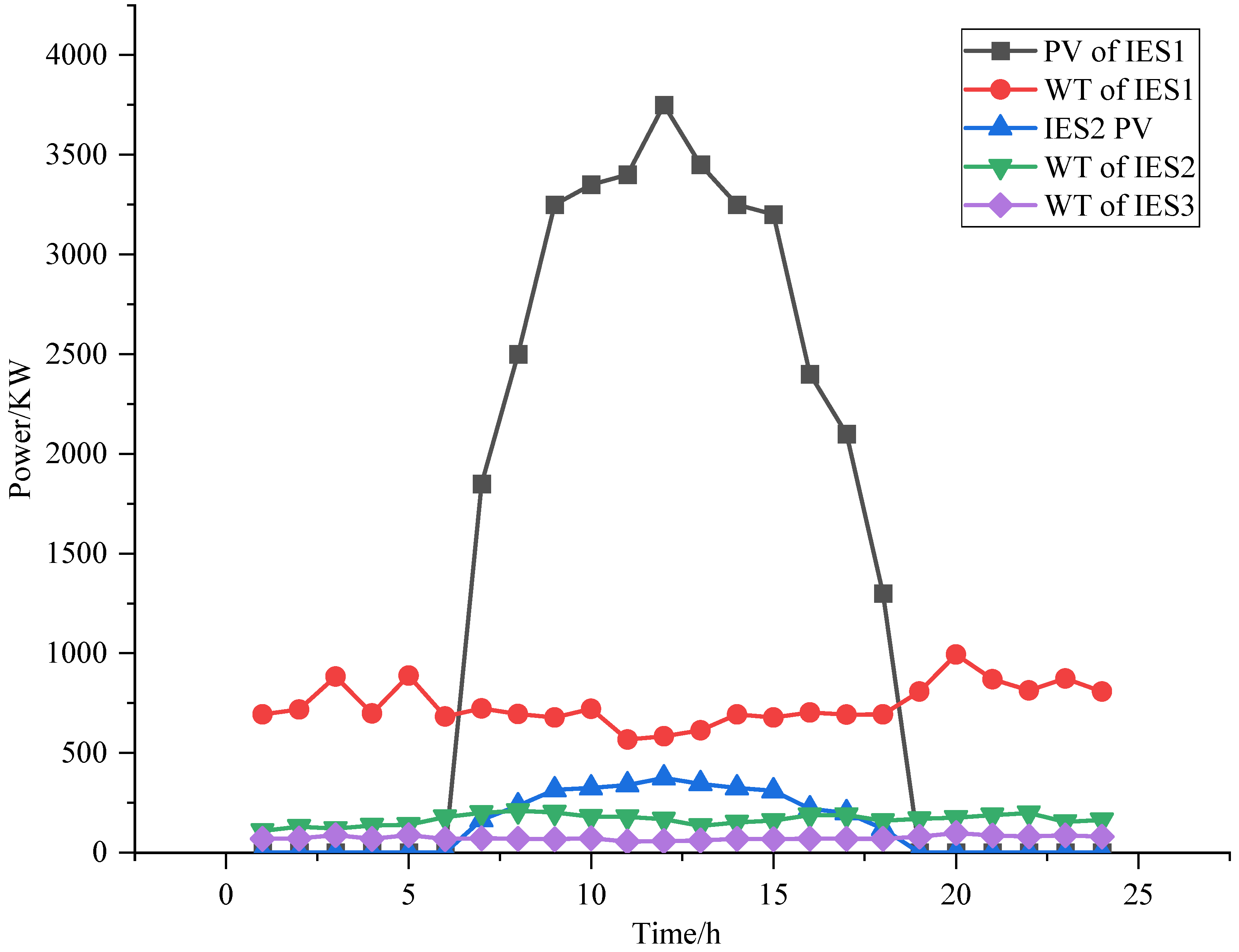
Figure 6 presents the forecasted power generation curves for wind and photovoltaic equipment within the three IESs examined in this study.
Figure 7 provides a detailed depiction of the electricity, thermal, and cooling load profiles for IES1 and IES3 during the scheduling period under consideration. Additionally,
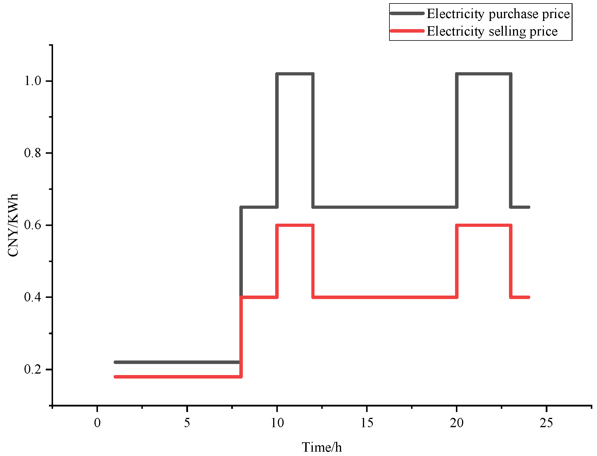
Figure 8 and
Figure 9 display the data for time-of-use electricity pricing and time-of-use heat pricing, respectively. The basic parameters of these three IESs are detailed in
Table 2.
4.2. Comparison of Optimization Results of Different Energy Scheduling Models
In
Table 3, in order to verify the necessity of the electricity–carbon joint scheduling, the case scenarios and solution results are shown below.
Table 4 and
Table 5 display the costs of different models, including operational costs and carbon trading costs for each model. In the comparison between Model 1 and Model 2, it is observed that the region’s carbon trading costs for all IESs using the carbon cooperation strategy have decreased by CNY 381.39, representing a reduction of 15.56% compared to the IESs operating independently. In the comparison between Model 1 and Model 3, it was found that the total cost in the region with power cooperation decreased by CNY 5913.59, representing a 7.14% reduction compared to the region where IESs operate independently. In the comparison between Model 4 and Model 3, it was observed that simultaneous carbon and power cooperation led to a reduction in carbon trading costs by CNY 406.28, with a reduction of approximately 18.20% compared to only conducting power cooperation. Upon examining
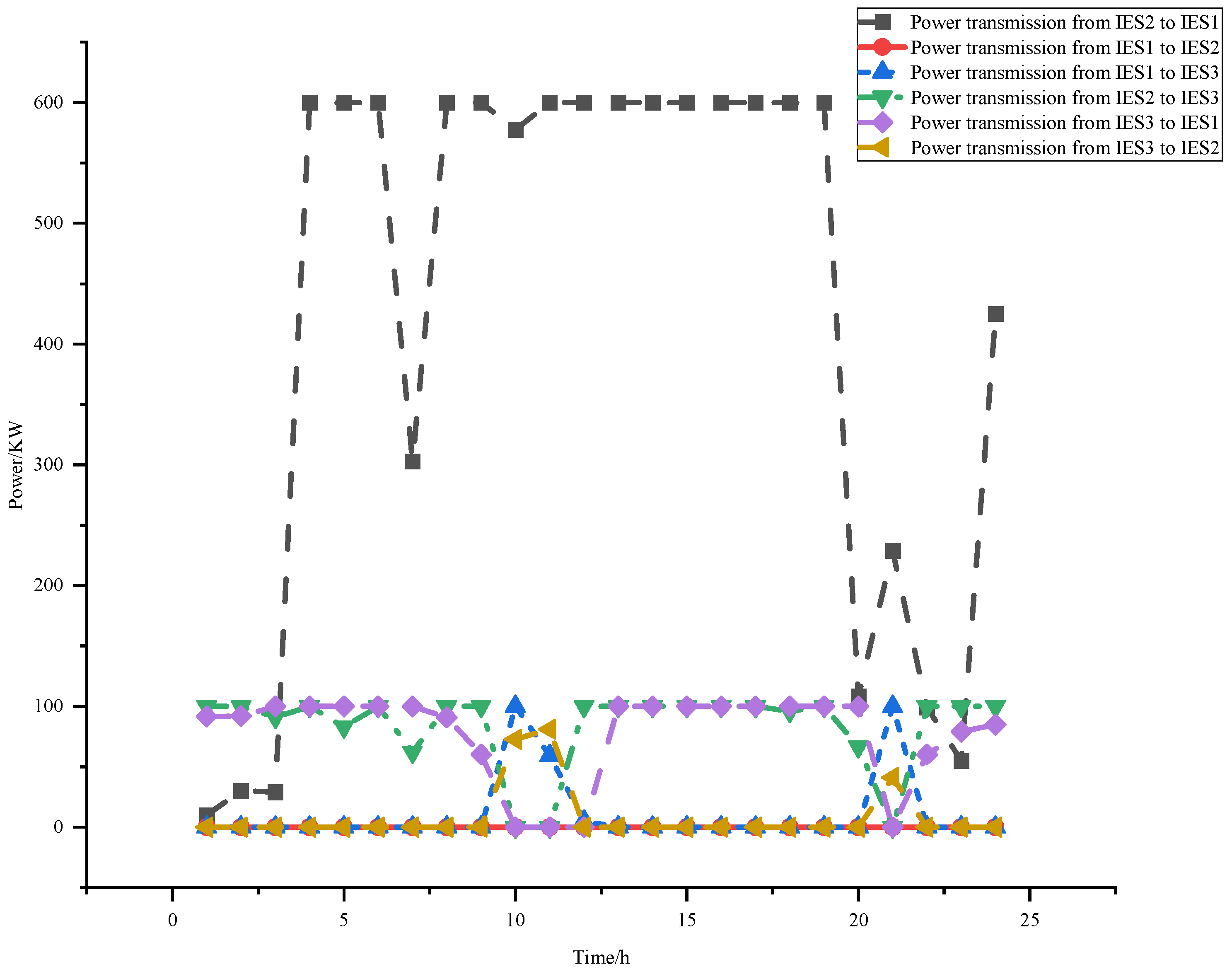
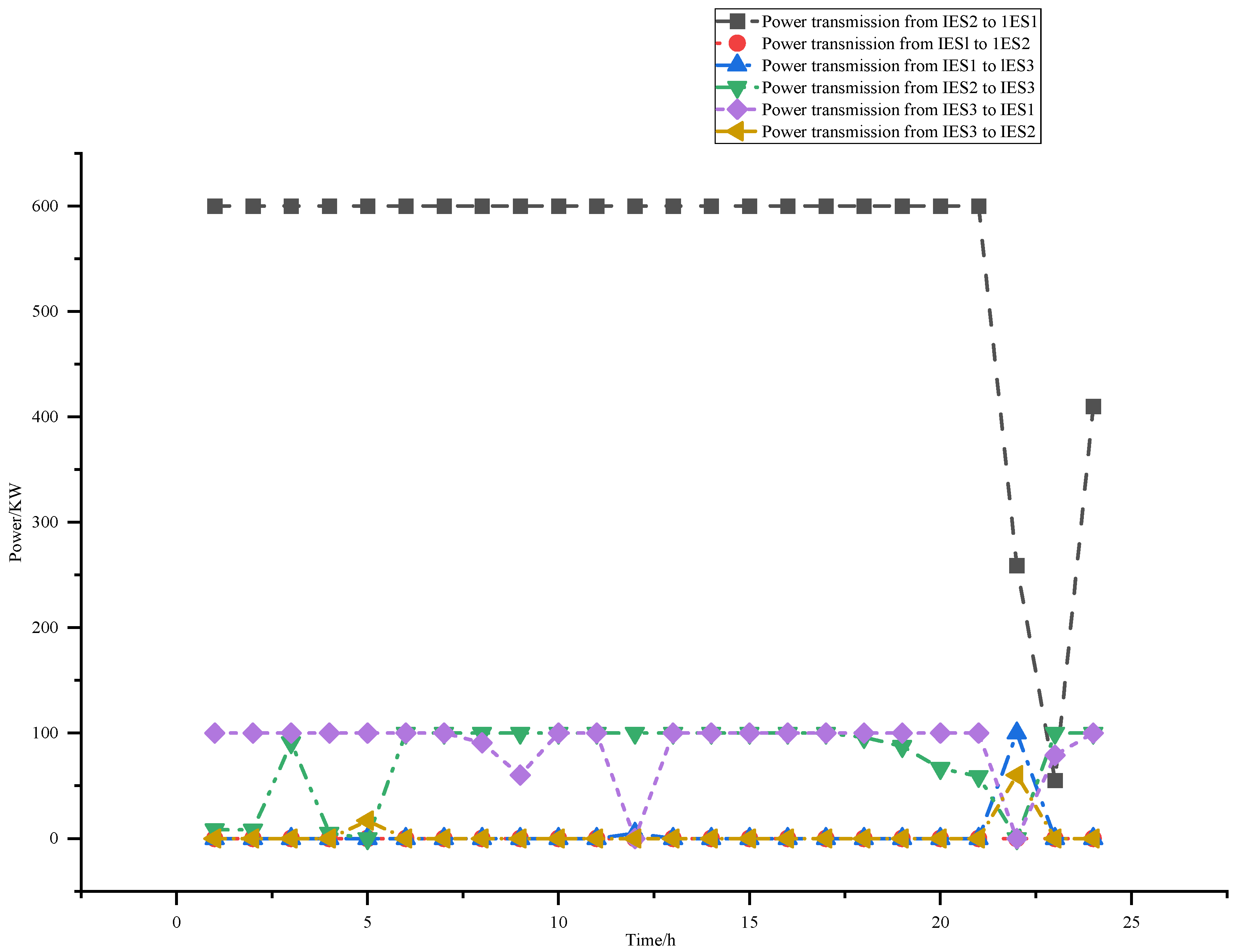
Figure 10, we can see that there is significant energy interaction occurring between the integrated energy systems, which is subject to transmission power limitations. Additionally,
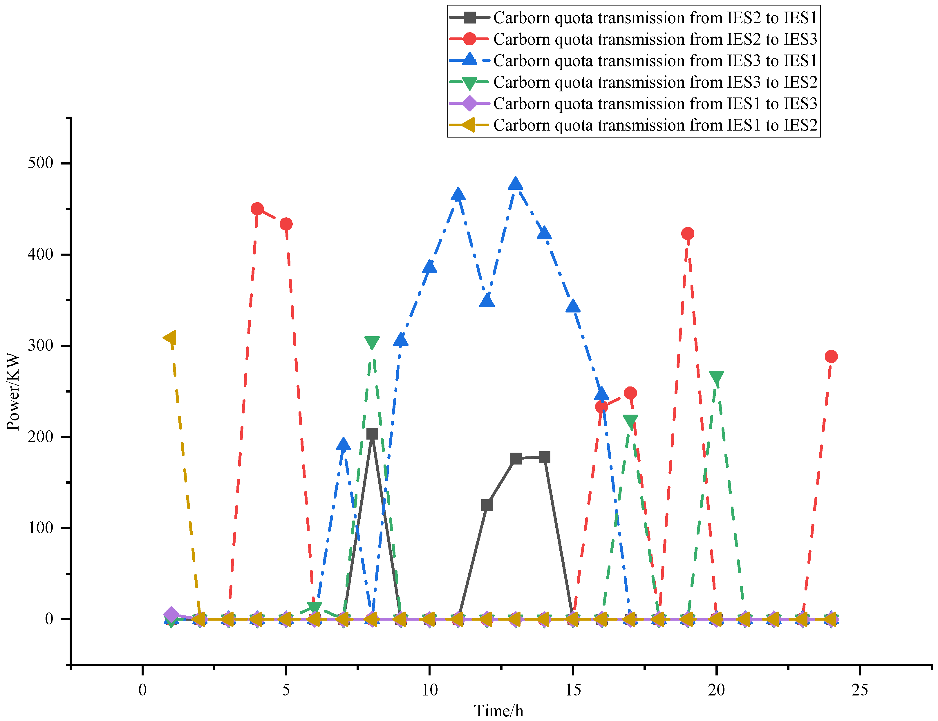
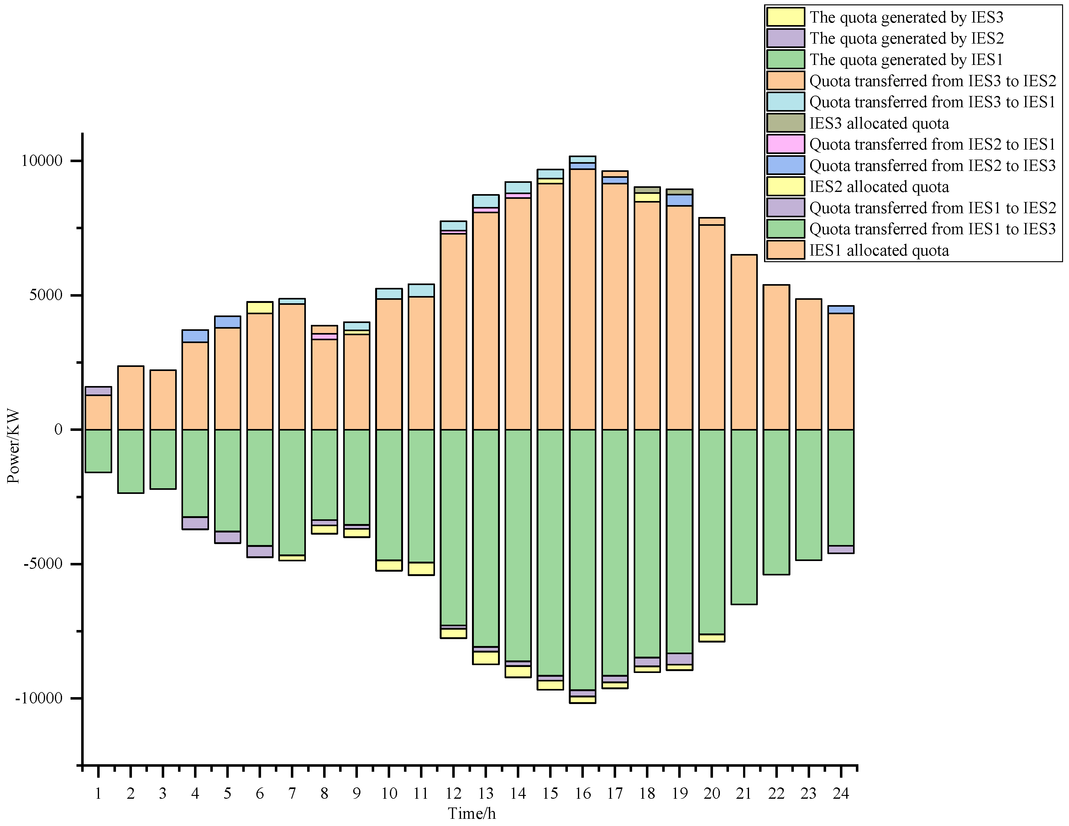
Figure 11 reveals an active phenomenon of carbon quota exchange between the IESs. These two mechanisms are the key drivers behind the reduction in both operational costs and carbon trading costs.
The effectiveness of carbon cooperation and power cooperation strategies was validated through the comparison between collaborative IESs and independently operated IESs in the previous sections. However, a detailed analysis of various aspects of operating costs in different models was not conducted. The table below shows the specific operating costs for different models.
Table 6,
Table 7,
Table 8 and
Table 9 respectively present the operational costs for different IESs under Models 1, 2, 3, and 4.
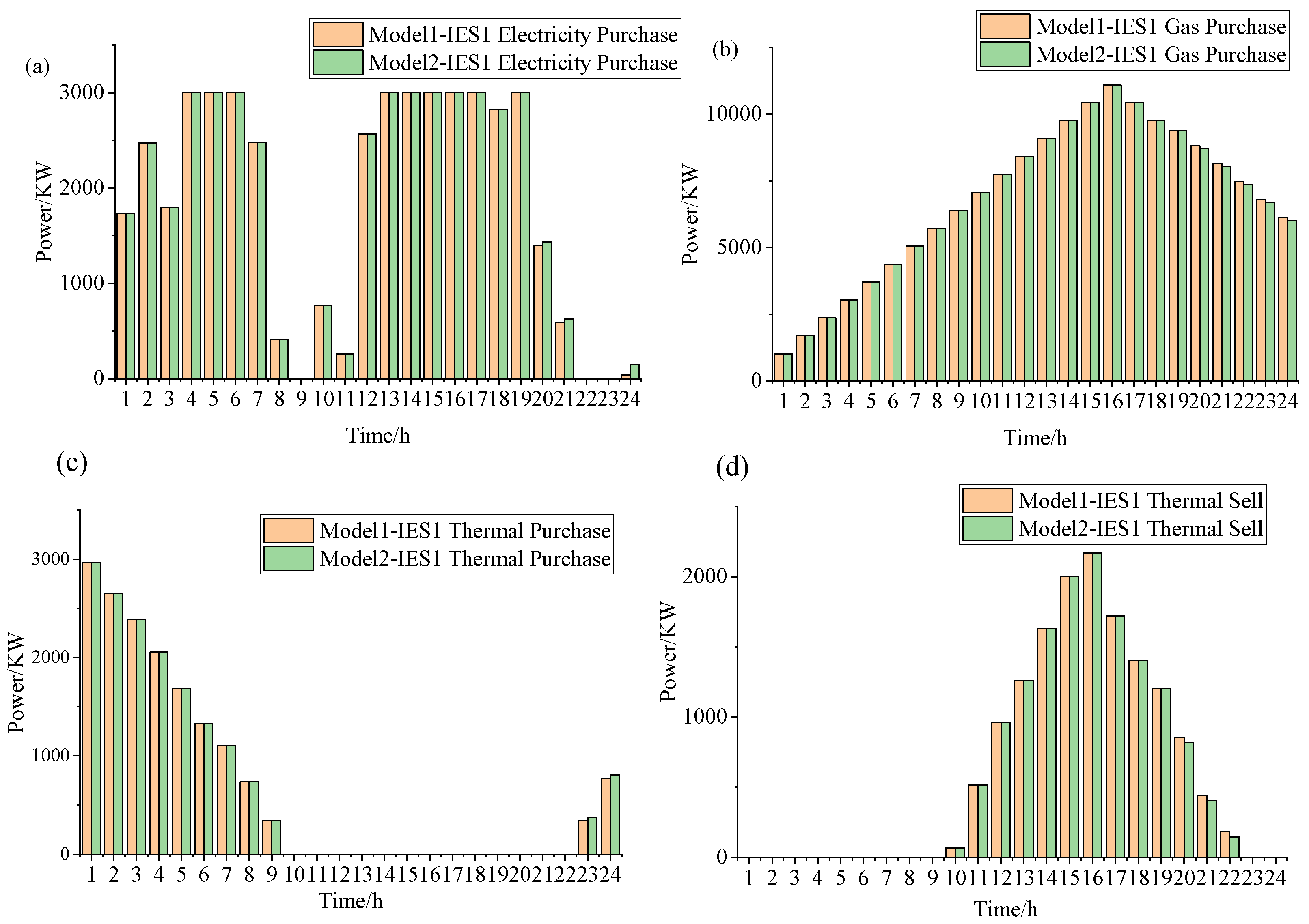
For the IES in Model 1 and Model 2, the different energy costs at different times are shown in the figure below.
Firstly, based on the natural gas prices in
Table 2 and information from
Figure 8, it is observed that the electricity purchased from the grid by the IES is cheaper than the natural gas price, but it has a higher carbon emission per unit. As shown in
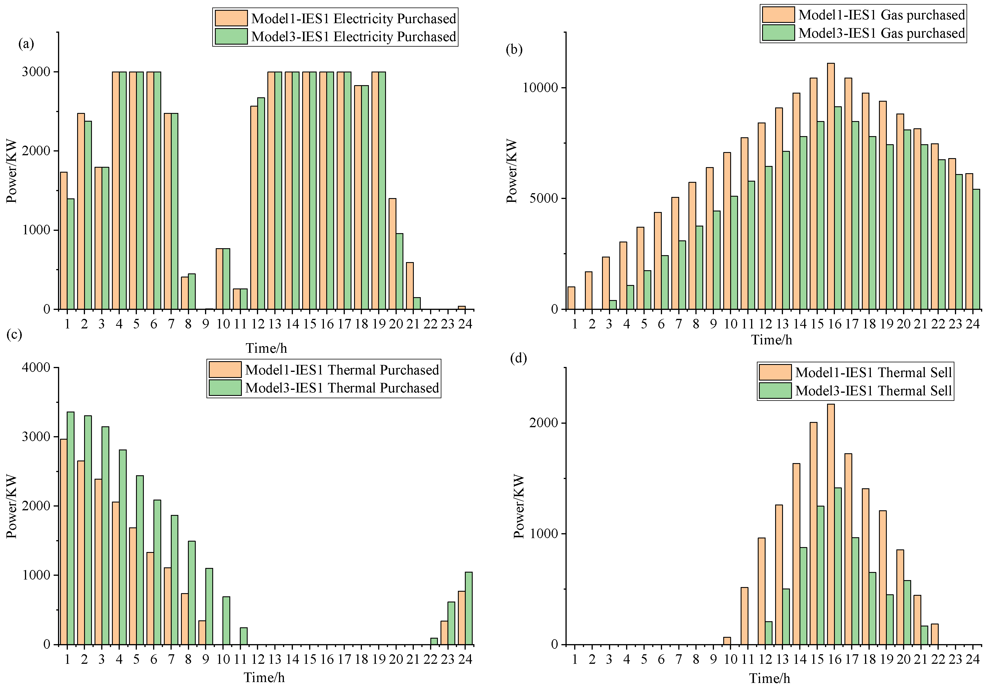
Figure 12, during periods of lower electricity prices, it is cost-effective to choose to purchase electricity rather than gas. Therefore, in Model 1 and Model 2, IES1 adopts the strategy of purchasing electricity from the grid, resulting in a constant total power of purchased electricity. When electricity prices are higher, even though increasing the purchase of natural gas leads to higher energy costs, the lower carbon emission per unit from gas compared to purchasing electricity will reduce carbon emission costs. Considering this, choosing to increase natural gas purchases is more cost-effective than increasing electricity purchases. As indicated in
Table 10, during the same period, IES1 in Model 2, participating in carbon cooperation, obtains carbon quotas from IES3, reducing the carbon cost pressure from purchasing electricity. Therefore, IES1 in Model 2 chooses to obtain more electricity from the grid. Through carbon cooperation, IES1 achieves a reduction in energy costs and carbon costs. Simultaneously, since carbon quotas are obtained from IES2, there is a loss of benefits for IES3. However, the reduction in energy costs and carbon costs by IES1 covers the increased carbon costs of IES3, resulting in an overall cost reduction in the region. For IES2 in Model 1 and Model 2, since it does not generate any carbon emissions itself, the carbon price has no impact on its own.
Based on the analysis of
Figure 13 and
Figure 14, it is clear that due to the power transfer limitations of the interconnection line, IES1 in Model 1 cannot access more cost-effective electricity and thus relies on more expensive natural gas for power generation. In contrast, under Model 3, IES1 is able to obtain cheaper electricity through the power transmission network facilitated by IES2 and IES3. Additionally, the carbon emissions resulting from electricity transmitted by other IESs are the responsibility of the transmitting IES, not IES1. This mechanism allows IES1 to achieve a dual reduction in carbon emissions costs and energy operational costs under Model 3, as shown in
Table 3.
Figure 14 reveals that IES3 transmits electricity to IES1 through IES2, a process influenced by the power limitations of IES3’s own interconnection line.
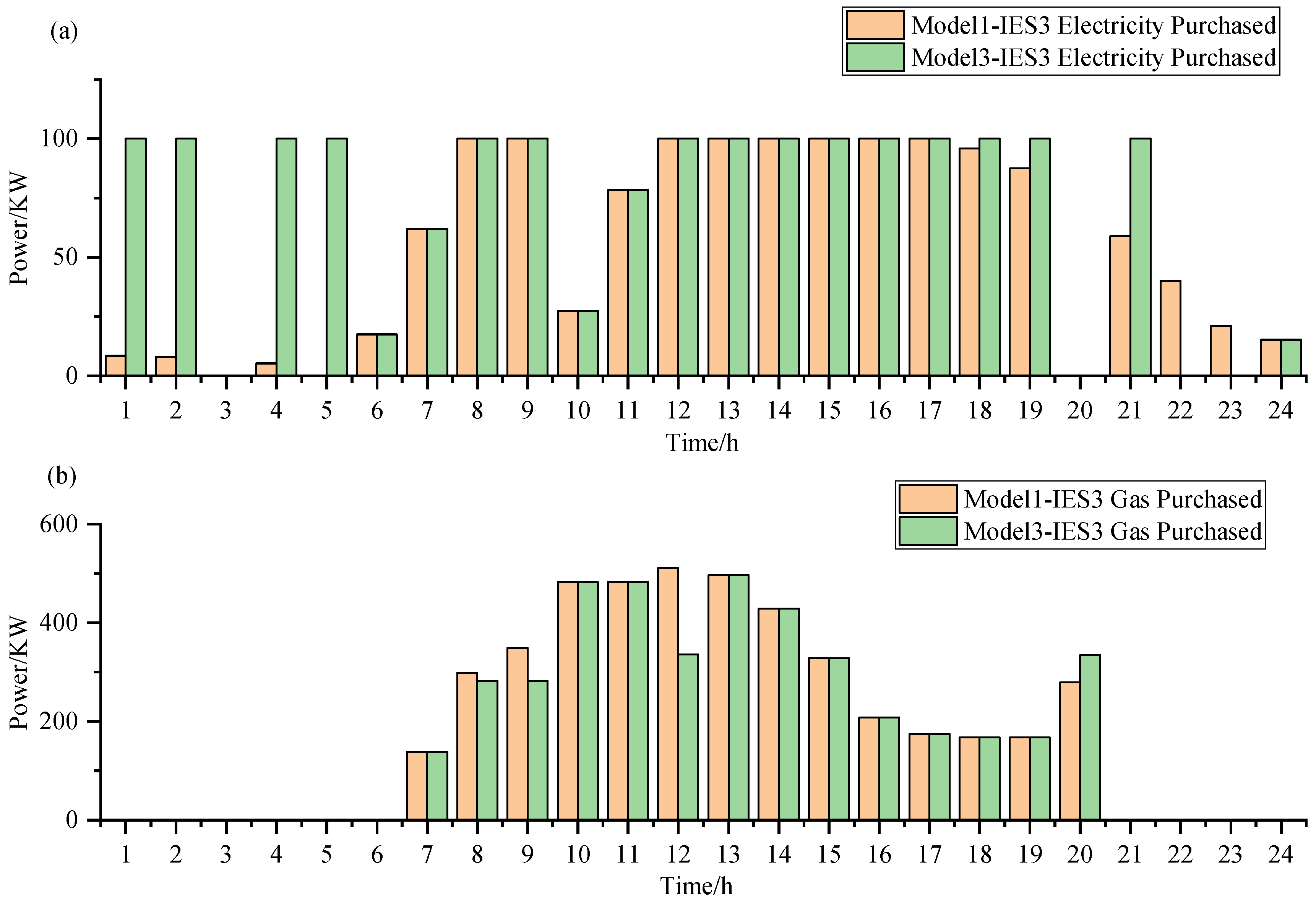
Figure 15 further illustrates the role of IES3, which not only transmits the electricity it generates but also procures electricity from the grid to supply IES1, effectively compensating for the reduced power output from IES1’s decreased natural gas generation. At the same time, IES1 has increased the thermal energy it obtains from the heat network. With these strategies, IES1 effectively reduces operational costs while meeting its own load requirements.
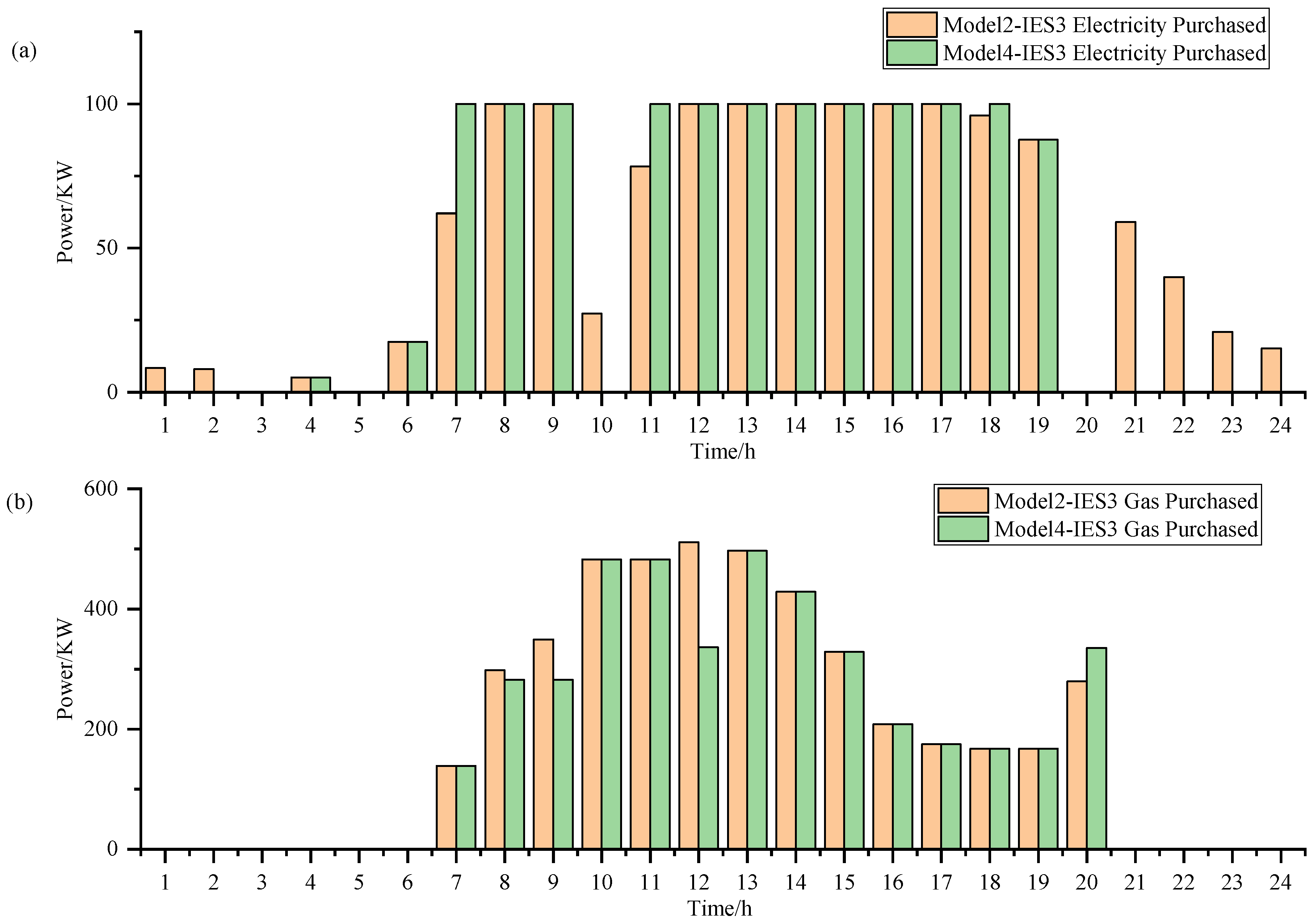
From
Figure 16 and
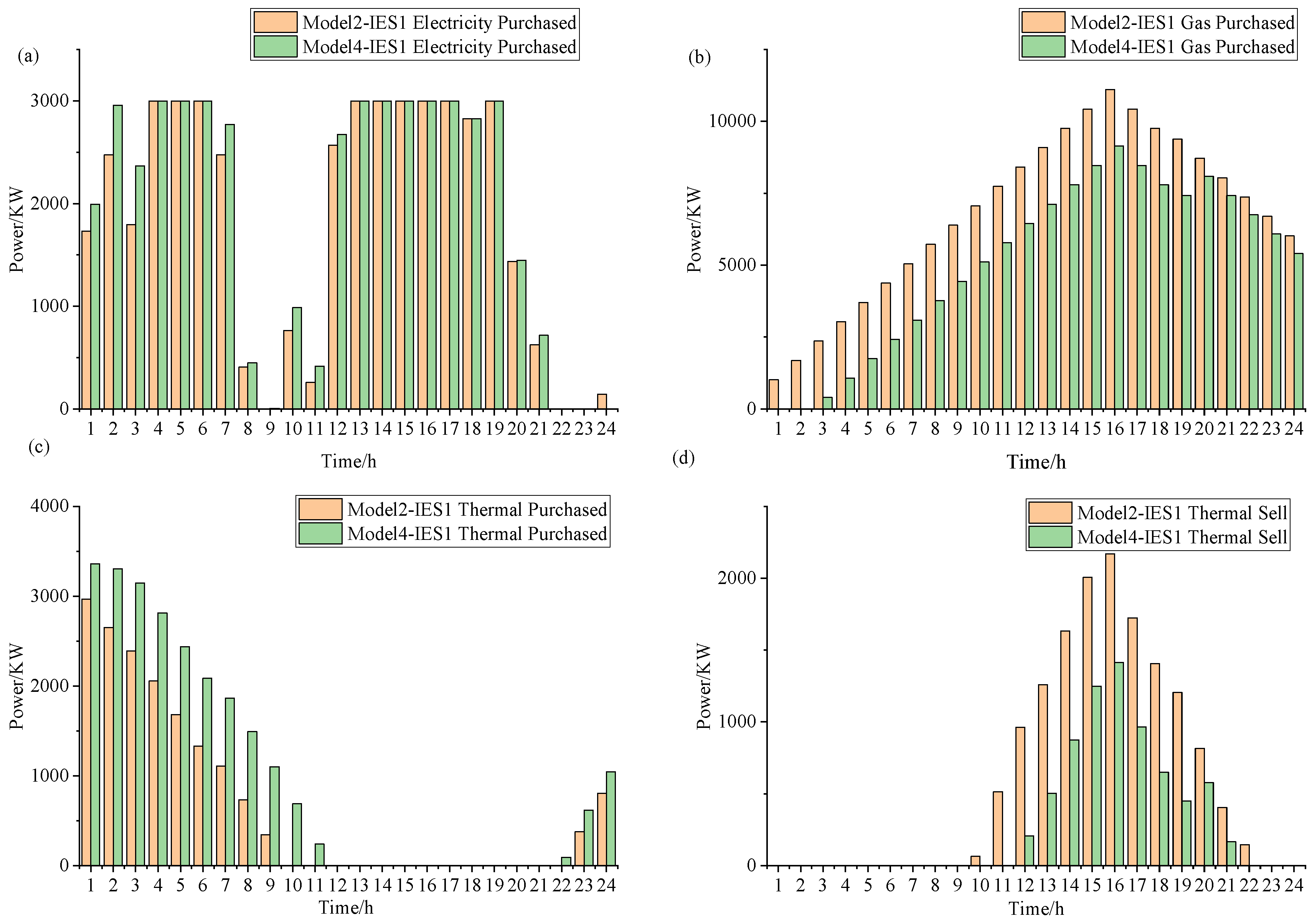
Figure 17, it can be observed that IES1 in Model 2 cannot obtain electricity from other IESs, resulting in the necessity of using gas for power generation. On the other hand, IES1 in Model 4 can access cheaper electricity, and carbon emissions are borne by other IESs. Therefore, the total energy cost of IES1 in Model 4 is smaller compared to Model 2. IES1 in Model 4 reduces energy costs more than the increase in energy costs for other IESs, leading to an overall decrease in total costs for all IESs in the region. However, Model 2 fails to achieve this, resulting in higher total costs compared to Model 4. From
Table 10, it can be seen that IES1 receives the most carbon quotas, as it has the highest carbon emissions, leading to the highest carbon costs. To reduce costs, it needs additional carbon quotas. In Model 4, IES1 in comparison to Model 2 benefits from IES2 purchasing electricity from the external grid, which incurs carbon costs. This results in the generation of corresponding carbon quotas. Consequently, IES1 in Model 4 receives more carbon quotas compared to IES1 in Model 2, leading to a greater reduction in regional carbon emission costs in Model 4.
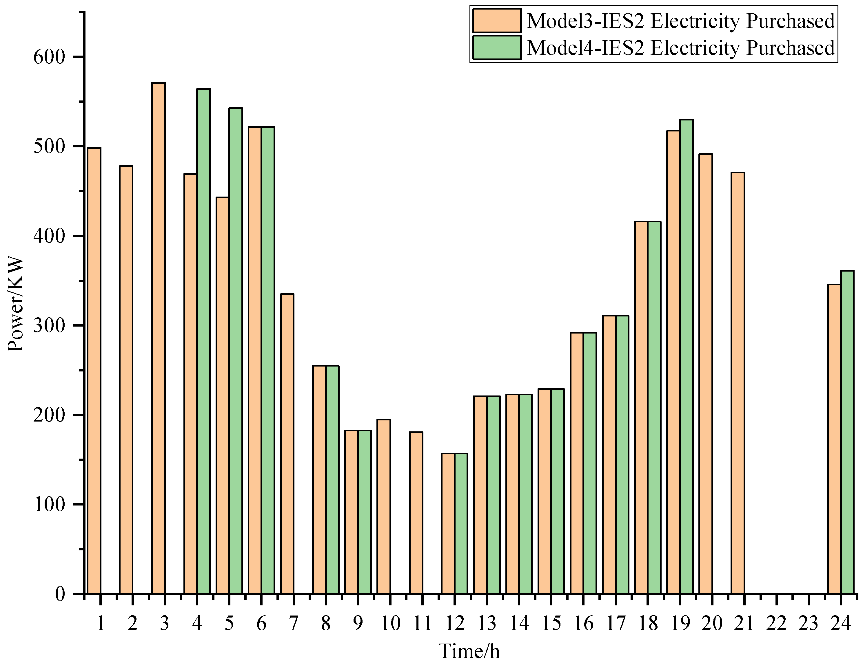
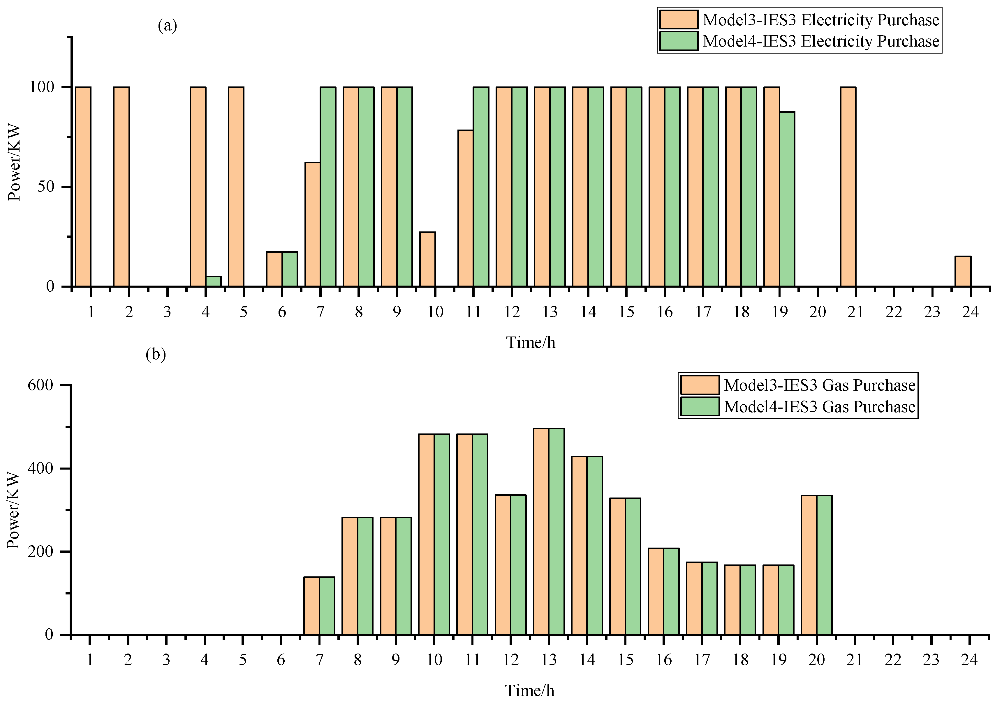
Based on the analysis from
Figure 18, we can infer that in Model 4, IES1 purchases more electricity from the external grid compared to Model 3. At the same time, due to the higher price of natural gas, the consumption of natural gas by IES across different models remains unchanged. Additionally, there are no significant changes in the activities of buying and selling heat from the heat network. Further observation from
Figure 19 and
Figure 20 reveals that IES2 and IES3 import less electricity from other IESs.
Although the carbon quota collaboration in Model 2 and the power collaboration in Model 3 resulted in a decrease in both carbon trading costs and energy costs compared to the original independent operation of IESs, Model 4 indicates that the electric–carbon joint scheduling further optimizes the costs of regional IESs compared to considering them separately.
4.3. Equipment Operation Scheduling Results and Carbon Scheduling Results of Model 4
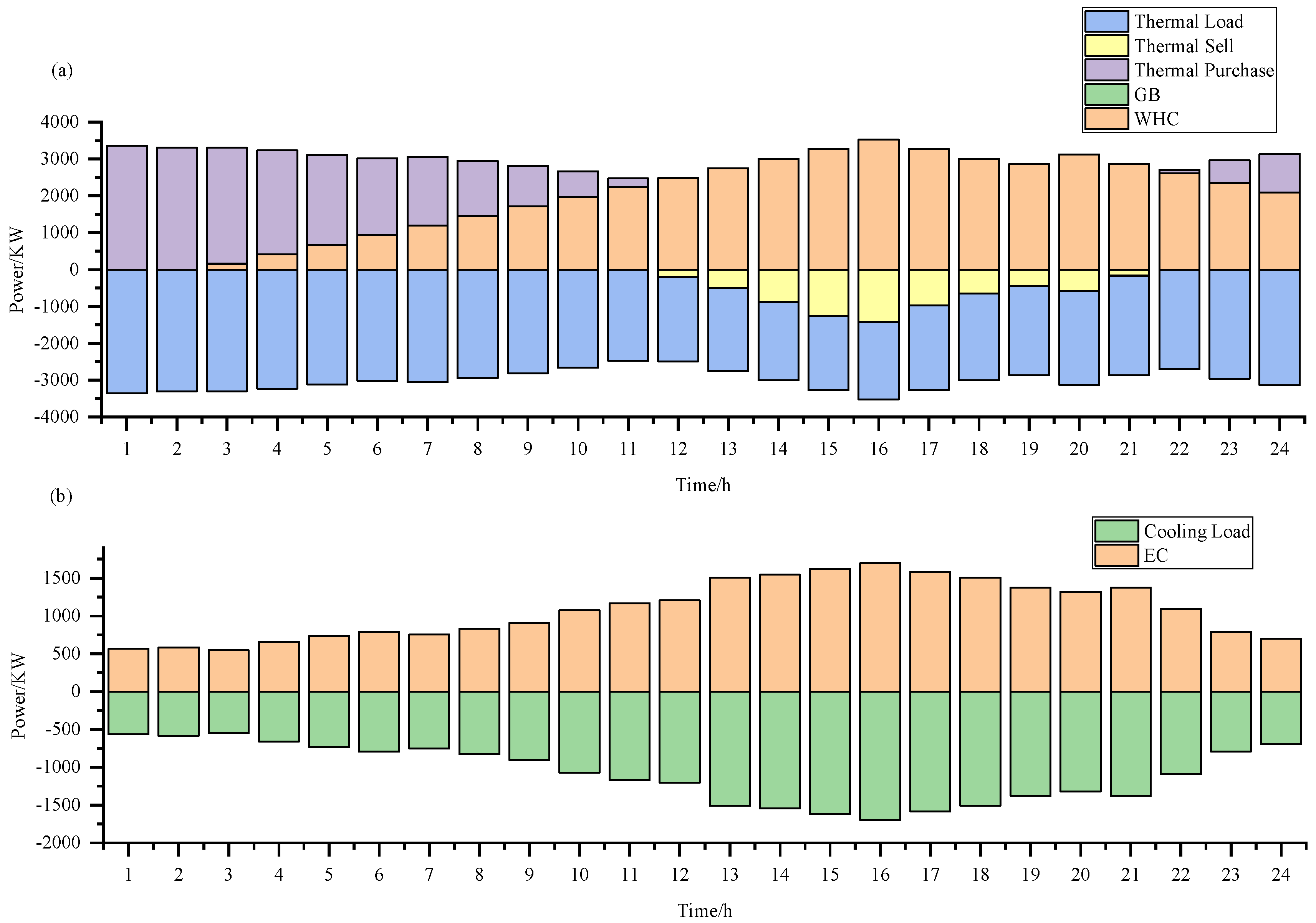
Under Model 4, the implementation results of the optimal operational strategy are detailed in the following figures:
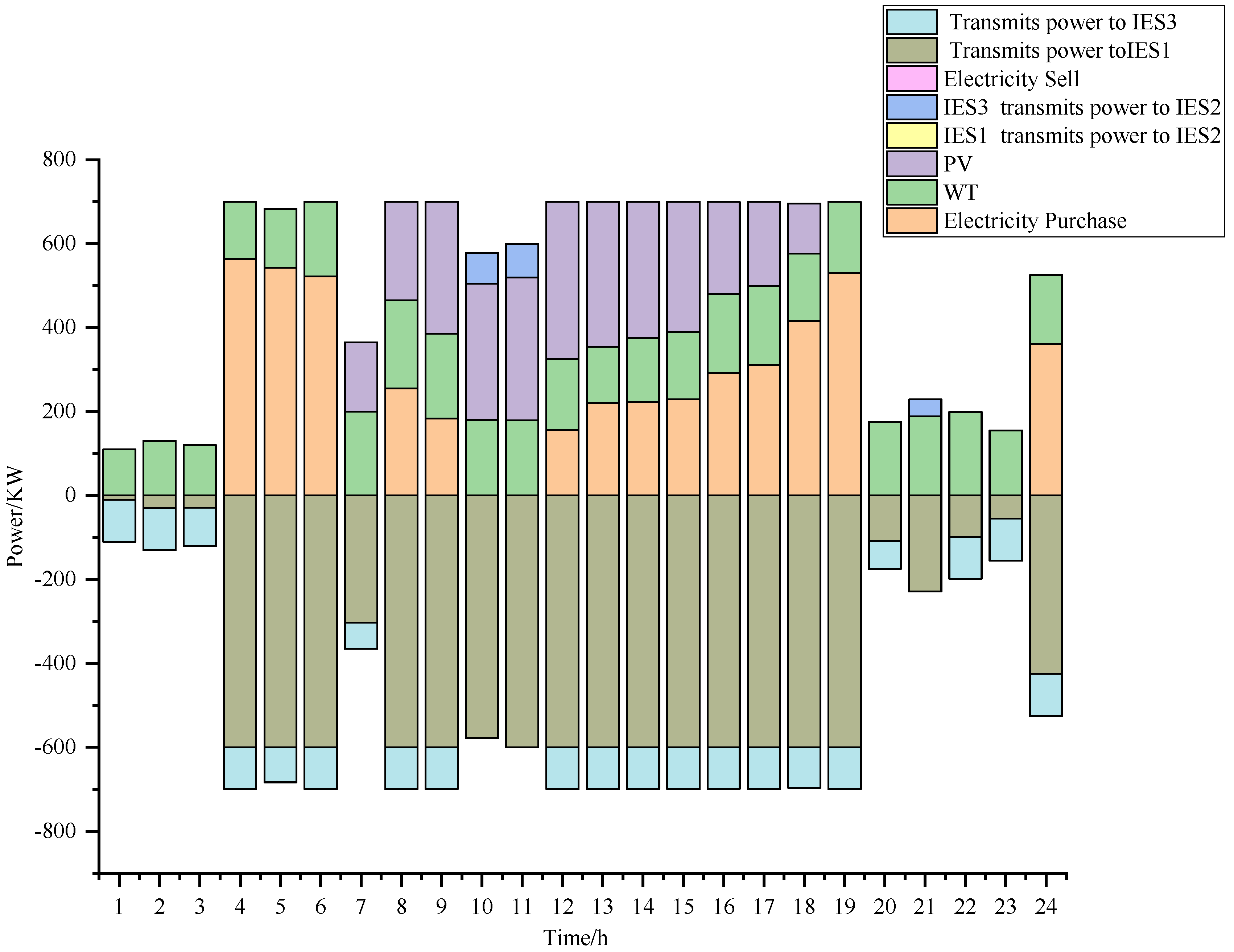
Figure 21 is dedicated to the electrical balance of IES1;
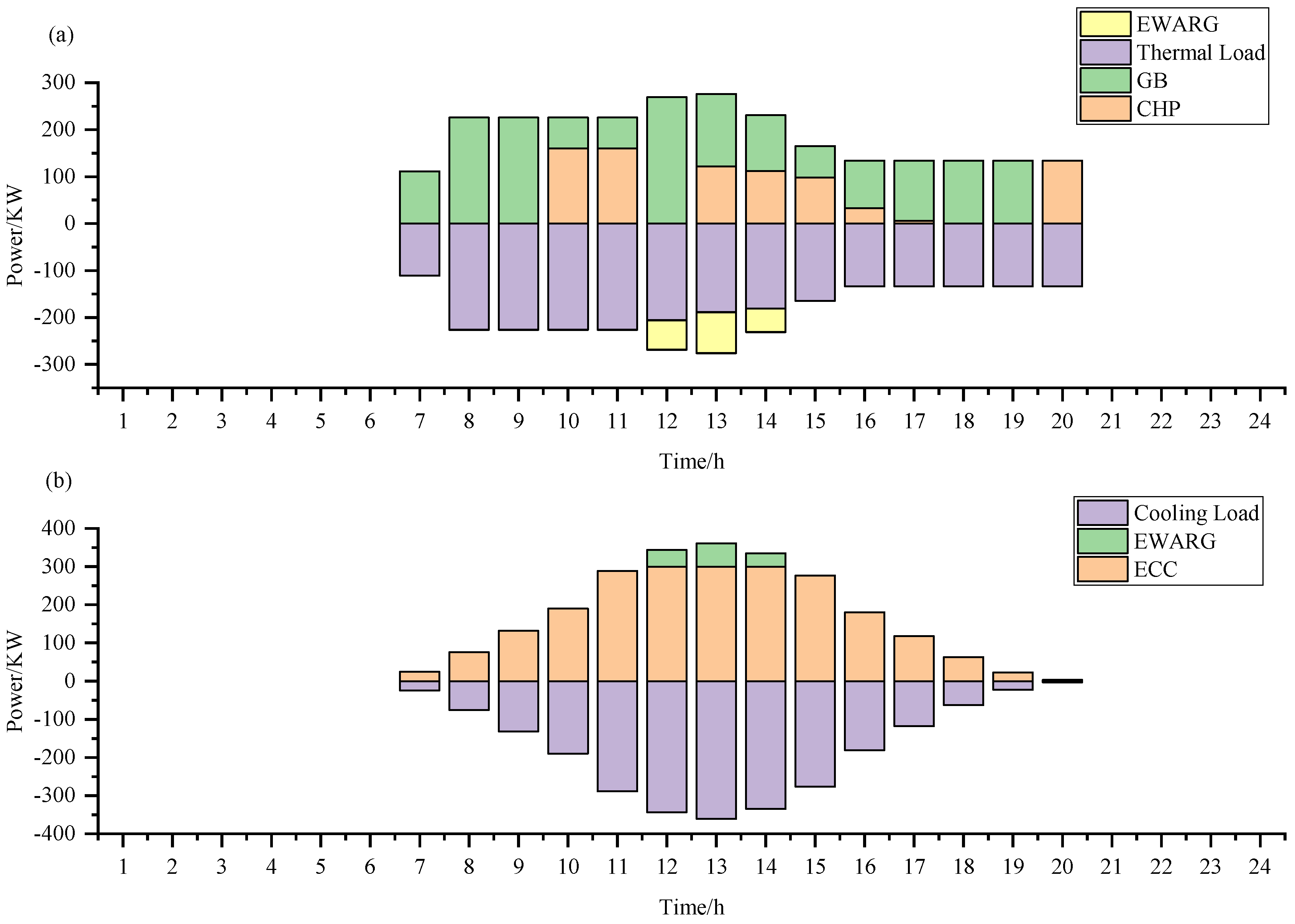
Figure 22 presents the thermal and cooling energy balance of IES1;
Figure 23 describes the electrical balance of IES2;
Figure 24 displays the electrical balance of IES3;
Figure 25 includes the thermal and cooling energy balance of IES3; and
Figure 26 illustrates the carbon quota balance for the entire region.
As shown in the scheduling results, energy coupling, energy distribution, and electricity transmission are accomplished within the IES, achieving the electrical, heating, and cooling balance for different IESs. During periods of low electricity prices, when electricity is relatively cheaper compared to gas, the IES purchases electricity. During peak energy demand periods, the IES discharges the electrical energy storage, generates electricity with gas turbines, and imports electricity from regions with a higher proportion of renewable energy. Notably, there is essentially no selling of electricity externally by the IES, completing the internal consumption of renewable energy electricity and achieving the full utilization of wind and solar power.
5. Conclusions
In the future, the energy systems are expected to be established at a large scale, forming clusters of IESs. These systems will integrate resources such as heating, cooling, and electricity, leading to increased resource interaction among different IESs, forming a larger interconnected whole. With the increasing emphasis on carbon emissions, there will be higher requirements for carbon emissions in the power system. Therefore, this paper proposes an MIES electricity–carbon joint scheduling model. By collaborating with regions with lower carbon emissions, transferring carbon quotas, and reducing the overall costs of high-carbon regions, the model aims to minimize regional costs. Simultaneously, in terms of power interactions, other IESs replace those operating independently, reducing the need for power generation through natural gas and consequently lowering costs. The conclusions drawn from the four cases of the electricity–carbon trading model are as follows.
- (1)
By establishing the joint scheduling model for electricity and carbon, a balance between carbon trading costs and energy consumption costs is achieved. This model maximizes the economic and environmental benefits between different regions, while simultaneously strengthening the connections between these regions.
- (2)
The electricity–carbon joint scheduling model proposed in this paper can effectively reduce the overall energy costs of regional IESs compared to the situation where systems operate independently. Moreover, the model significantly reduces carbon costs, and this research finding further confirms the effectiveness of this strategy.
- (3)
From the analysis in
Section 4.2, it is observed that due to differences in carbon prices among regions, areas with higher carbon emissions will strengthen cooperation with regions having lower carbon emissions. This paper contributes to breaking down barriers between different IESs in different regions.
In the current integrated energy systems, although users are provided with various forms of energy such as electricity, heat, and cooling, the system has not fully guided users to change their traditional energy consumption habits. Therefore, future research should focus on exploring how to incentivize users to actively participate in demand response programs, by adjusting their energy usage patterns to better adapt to the real-time demands and market changes in the power grid.
