Article

The Performance Evaluation of a Hybrid System Combining an Alkaline Fuel Cell with an Inhomogeneous Thermoelectric Generator

1
PetroChina Research Institute of Petroleum Exploration & Development, Beijing 100083, China
2
Doerr School of Sustainability Energy Sciences Engineering Department, Stanford University, 397 Panama Mall, Stanford, CA 94305, USA
3
SLB Software Technology Innovation Center (STIC), 2700 Sand Hill Rd, Menlo Park, CA 94025, USA
*
Author to whom correspondence should be addressed.
These authors contributed equally to this work.
Energies 2024, 17(9), 2066; https://doi.org/10.3390/en17092066
Submission received: 12 March 2024 / Revised: 4 April 2024 / Accepted: 11 April 2024 / Published: 26 April 2024
(This article belongs to the Special Issue New Trends and Research in Fuel Cells and Energy Conversion/Storage)

Abstract

:
To harness the full potential of the exhaust heat produced by an alkaline fuel cell (AFC), a novel coupling system that combines an AFC with an inhomogeneous thermoelectric generator (ITEG) is proposed. Detailed models of both the AFC and ITEG are developed, accounting for various irreversible losses. Following model validations, mathematical expressions for the power output density (POD) and energy efficiency (EE) of the hybrid system are derived. Though performance comparisons, the hybrid system’s effectiveness and competitiveness are demonstrated. Our calculation results reveal that the hybrid system achieves a 31.19% increase in its maximum POD and 54.61% improvement in its corresponding EE compared to that of the standalone AFC. Furthermore, numerous parametric studies are conducted. Some findings indicate that the POD of the hybrid system can be improved by elevating the operating temperature of the AFC and the environmental temperature, and that it can be optimized using the geometric characteristics of an ITEG. However, the EE of the hybrid system gains improvement via increasing the operating temperature of the AFC or decreasing both the environmental temperature and geometric characteristics of the ITEG. Additionally, the coefficient of the spatial inhomogeneity of the ITEG determines the optimal operating current density of the AFC. These insights offer valuable guidance for the integration and operation of practical hybrid systems.

1. Introduction

Depleting fossil fuel reserves and escalating environmental pollution demand urgent attention. The urgent need for efficient and eco-friendly energy technologies to address this is evident [1]. In this context, fuel cells have emerged as a promising solution, offering the potential to effectively address both the energy crisis and environmental degradation [2]. Notably, low-temperature fuel cells (L-TFCs) have garnered widespread interest across various applications, including space missions, power generation, portable devices, and transportation. This is attributed to their notable advantages, such as their mature technology, lower starting temperatures, and enhanced safety features [3]. Within the realm of L-TFCs, alkaline fuel cells (AFCs) are experiencing a revival due to their distinctive features. These include lower costs, heightened durability, effective internal thermal management, and the ease of contamination removal [4].
Nevertheless, the broad-scale commercialization of AFCs faces a significant obstacle due to their inherent drawback of a relatively lower power density [5]. Addressing this challenge has prompted substantial efforts on various fronts, including the enhancement of their electrode materials, fuel cell design, and catalysts, and the optimization of their operating conditions [6]. Moreover, an alternative avenue for improving AFCs’ power density lies in the recovery and utilization of the exhaust heat generated within AFCs. This can be achieved through integrated heating and power systems. For instance, Zhang et al. [7] utilized a thermoradiative device to capture the valuable waste heat from an AFC, enhancing its performance. The maximum power output density (MPOD) of the hybrid system was found to be 1.75 times higher than that of the standalone AFC. Zhu et al. [8] introduced a pioneering hybrid system that integrated an AFC with air gap membrane distillation (AGMD). The goal was to boost its power density by harnessing the waste heat from the AFC for freshwater generation by utilizing the AGMD. Their calculations indicated that the equivalent MPOD could be 63.28% higher than that of the standalone AFC as it was operating at 353 K. Zhao et al. [9] established a hybrid system that integrated an irreversible absorption refrigerator (IAR) with an AFC. After the AFC cycle, a large amount of waste heat was then transferred into and drove the IAR’s cooling application. This hybrid system enhanced its MPOD by 2.6% and its corresponding efficiency by 3.0%, compared to those of the standalone AFC. Zhao et al. [10] investigated a hybrid system comprising an AFC and a direct contact membrane distillation unit, enabling the co-generation of electricity and freshwater. The MPOD and maximum energy efficiency (MEE) of this hybrid system were found to be 144.58% and 144.55% higher, respectively, than those of the standalone AFC. Zhang et al. [11] introduced a hybrid system consisting of an AFC, a thermally regenerative electrochemical cycle (TREC), and a regenerator. Their simulations showed that when the TREC operated within the range of 0.4 to 0.8, the MPOD of the hybrid system was 1.46–1.77 times higher than that of the standalone AFC. Zhu et al. [12] proposed a combined system by using an AFC and elastocaloric cooler (ECCR), in which the ECCR can efficiently recycle byproduct waste heat. The study indicated that the equivalent MPOD and its corresponding energy efficiency can be increased by 51.64% and 20.88%, respectively, compared to that of a single AFC. Additionally, Wang et al. [13] proposed a thermal–electric hybrid system that was comprised of an AFC and a thermogalvanic cell (TGC). In this thermal–electric hybrid system, the TGC recycled the large amount of waste heat from the AFC for additional power generation. This hybrid system gained an obvious rise of 19.72% in its MPOD (from 247.07 W m−2 to 295.80 W m−2) and 5.71% in its energy efficiency (from 10.16% to 10.74%) compared to a standalone AFC.
Lately, thermoelectric generators (TEGs) have gained significant recognition as a prominent player in the field of thermal energy conversion [14,15]. This popularity is attributed to their straightforward operational principles, low maintenance requirements, environmentally friendly characteristics, compact and robust design, and reliable performance even in challenging environmental conditions [14]. Consequently, TEGs are widely applied in the heat recovery of various heat resources. For example, Zhao et al. [16] successfully integrated perovskite solar cells (PSCs) with thermoelectric generators (TEGs), optimizing their performance for broad-spectrum usage. With the assistance of TEGs, their hybrid system achieved a MPOD of 22.36%, which was 13.68% higher than that of the standalone PSC. Kandil et al. [17] investigated a photovoltaic/thermoelectric generator (PV/TEG) hybrid system with a beam-splitting configuration. This hybrid system exhibited an enhanced average power output density (POD), increased by nearly 43% compared to that of the standalone PV system. Zhao et al. [18] put forward a solar hybrid system that combined a two-stage TTEG with a dye-sensitized solar cell (DSSC). This system was designed to efficiently capture sunlight across a broad spectrum. Comparatively, this hybrid system improved upon these figures with a 4.33% increase in its MPOD and a remarkable 64.25% enhancement in its MEE when compared to the standalone DSSC. Manivannan et al. [19] integrated solar heat pipes with a TEG using the IoT. Their results showed an efficiency improvement with a concentrator. A carbon credit analysis highlighted the environmental benefits, while real-time temperature monitoring with Arduino demonstrated its IoT application. Additionally, Yang et al. [20] employed a TEG to harvest the large amount of exhaust heat produced by the AFC for additional power generation. As a result, the MPOD of the hybrid system increased by up to 23% compared to that of the standalone AFC.
The study referred to in reference [20] underscores the competitiveness and effectiveness of integrating a TEG into an AFC. However, the TEG utilized in this hybrid system is of a homogeneous type. While the homogeneous TEG employed showcased certain advantages, it failed to address the thermal stress caused by a nonuniform temperature distribution, leading to reliability issues. In contrast, an inhomogeneous TEG (ITEG) could emerge as an optimal solution for thermal recovery applications due to its capacity to customize its thermoelectric properties and gradients to match specific temperature profiles [21]. By adapting well to nonuniform temperature distributions, the ITEG offers enhanced stability and efficiency. In terms of the research of the ITEG’s heat recovery application, Zhang et al. [21] employed this ITEG to harvest the thermal energy from a U-tube solar collector (EUSC), thus achieving the efficient thermal-to-electric conversion. An outstanding power density (26.1 W m−2) and an efficiency (2.61%) under the condition of AM 1.5 were gained, suggesting significant potential applications for the ITEG in EUSCs. Similarly, the waste heat recovery within the AFC is in roughly the same operating temperature range as that of solar power generation systems. Based on this, an attempt was made to integrate an ITEG into a solar power generation system. Therefore, the coupling of an ITEG with an AFC could present a more favorable approach for achieving both high efficiency and operating stability. However, the performance attributes of this hybrid system configuration are currently undisclosed, warranting further investigation into its technological feasibility and potential.
To address this research gap, a novel hybrid system integrating an AFC and an ITEG is proposed in theory, with the aim of maximizing the utilization of the exhaust heat from the AFC. Accounting for various irreversible losses, the mathematical model development of this hybrid system is conducted. Following model validation, the hybrid system’s generic performance features are uncovered. Furthermore, comprehensive parametric studies are carried out to analyze how the hybrid system’s performance is impacted by key design parameters and operational conditions, identifying the rules for improving its performance. The novelties of the current work are summarized as follows: (1) This is a pioneering application of an ITEG for AFC waste heat recovery. This hybrid system utilizes an ITEG to recover the waste heat from an AFC, achieving improved conversion efficiency. (2) It contains a comprehensive performance evaluation. An in-depth assessment of the performance potential of this hybrid system is conducted, showcasing its superiority over other AFC-based hybrid systems through rigorous comparisons. (3) Performance improvement pathways are identified. By investigating the effects of various design parameters and operational conditions on the hybrid system’s performance, this study identifies potential avenues for enhancing the hybrid system’s performance.

2. System Description

The proposed hybrid system’s layout is illustrated in Figure 1a. This coupling system comprises an AFC, an ITEG, and a regenerator. Additionally, this hybrid system is modeled and simulated using the MATLAB® 2022a [22] tool, which was developed by MathWorks and provides a vast array of built-in functions and tools for various tasks, including mathematical modeling, algorithm development, and simulation. The AFC converts hydrogen energy into electrical power P A through electrochemical reactions, simultaneously producing vast amounts of high-temperature exhaust containing waste heat. The regenerator is utilized to preheat the incoming fuel and oxidant using the high-temperature exhaust from the AFC. Additionally, the ITEG captures the waste heat from the AFC to generate additional electricity P I . As a result, the hybrid system achieves an improved performance compared to the standalone AFC. In Figure 1, T and T 0 are, respectively, the operating temperature and environmental temperature; Q L o s s , Q H , and Q L are, respectively, the heat leaked from the AFC to the environment, the heat input into the ITEG, and the heat output by the ITEG.
To effectively assess the hybrid system’s performance while maintaining accuracy and feasibility, the following assumptions are carefully adopted:
(1)
The entire hybrid system runs under steady-state conditions [23];
(2)
The provision of oxygen and hydrogen are assumed to be perfectly regulated based on the electric current generated, considering that hydrogen can be recycled in practical operations [24];
(3)
The ITEG neglects the Thomson effect of thermoelectric elements and permits electric current to flow through the device’s arm [25];
(4)
The average Seebeck coefficient of the ITEG is treated as a constant at a constant temperature, and the ITEG’s geometry is assumed to be in its optimal configuration [26].

2.1. Alkaline Fuel Cell

The AFC, as an electrochemical device, has the capability to directly convert the chemical energy within its reactants into both electricity and thermal energy. Illustrated in Figure 1b, this device is composed of an anode, a cathode, and an electrolyte (KOH solution) positioned between the two electrodes. Hydrogen and oxygen serve as the fuel and oxidant, respectively, supplied to the anode and cathode. Within the anode, H2 reacts with the OH ions in the electrolyte to form H2O and electrons. These electrons then traverse the external electric circuit. Simultaneously, in the cathode, O2 reacts with H2O to produce OH- ions, facilitated by the electrons from the external electric circuit. The AFC’s power output (PO) and energy efficiency (EE) can be determined using the equations presented in Table 1.

2.2. Inhomogeneous Thermoelectric Generator

The ITEG includes multiple thermoelectric elements (TEs). Each TE is manufactured using p- and n-type semiconductors, and these semiconductor legs are thermally linked in parallel while electrically interconnected in series. The operation of the ITEG involves Peltier heat flow and Joule heating due to the electrical resistance of the semiconductor, as well as heat flow due to the temperature gradients at the junctions of the hot and cold sides, as shown in Figure 1c. The Seebeck coefficient α T , internal resistance R = ρ p + ρ n / L T , and thermal conductance K = κ p + κ n L T are considered in the current model of the ITEG. The current ITEG employs the material Bi2Te3, and its material properties, dependent on temperature, can be found in Table 2. Subsequently, the heat absorbed on hot side and heat released from cold side of the ITEG are calculated by [27]
Q H = n α T T I I T E G + K 1 d T T 0 1 w R I I T E G 2
and
Q L = n α T T 0 I I T E G + K 1 d T T 0 + w R I I T E G 2
where L T = S / L is the thermoelement geometry factor; L and S are the cross- length and the sectional area of a TE, respectively; n is the number of TEs; I I T E G is the operating current of the ITEG; w is the ratio of the Joule heating on the cold side to the total Joule heating of the TE; w = 1 d / 2 d ; and d is an index characterizing the inhomogeneous or homogeneous state of the thermoelectric material, and it falls within 0 d < 1 . The thermoelectric materials are homogeneous when d = 0 , and generally greater homogeneity demands a smaller d . Accordantly, the expressions for the PO and EE of the ITEG can be, respectively, defined as
P I = Q H Q L = n α T I I T E G T T 0 n R I I T E G 2
and
η I = P I Q H = α T I I T E G T T 0 R I I T E G 2 α T T I I T E G + K 1 d T T 0 1 w R I I T E G 2

2.3. Regenerator

The regenerator within the current hybrid system plays a crucial role by warming the inlet reactants from T 0 to T using the high-temperature exhaust gases from the AFC. However, due to the inherent irreversibility of heat transfer, some regenerative losses are unavoidable. These losses are typically assumed to be proportional to the temperature difference between the AFC and the environment [20].
Q r e = K r e A r e 1 χ T T 0
where K r e , A r e , and χ are, respectively, the heat transfer coefficient, heat transfer area, and effectiveness of the regenerator. Furthermore, when the regenerator is ideal (i.e., χ = 100 % ), no additional heat input is required.

2.4. Hybrid System

In this hybrid system, all the waste heat from the AFC is utilized by the ITEG for additional power, such that an energy balance must be satisfied:
Q W = Q H
where Q W = Δ H · P A Q r e Q L o s s is the waste heat from the AFC; Q L o s s = K L A L T T 0 ; and K L and A L are, respectively, the heat leak coefficient the effective heat transfer area.
For solving Equation (17) and satisfying the condition of P I > 0 , the hybrid system runs normally only when I I T E G varies with the following range:
0 < I I T E G < α T T T 0 / R
where I I T E G = n T α T   ±   n 2 T 2 α T 2   +   4 n R w 1 n K 1 d T 0 T   +   Q W 2 n R w 1 .
Within the operating conditions in Equation (18), the POD and EE of the hybrid system can be, respectively, calculated using
P = U c e l l J + α T I I T E G T T 0 R I I T E G 2 / A A I
and
η = U c e l l I + α T I I T E G T T 0 R I I T E G 2 Δ H ·
where A A I is the effective heat transfer area between the AFC and ITEG.

3. Model Validation

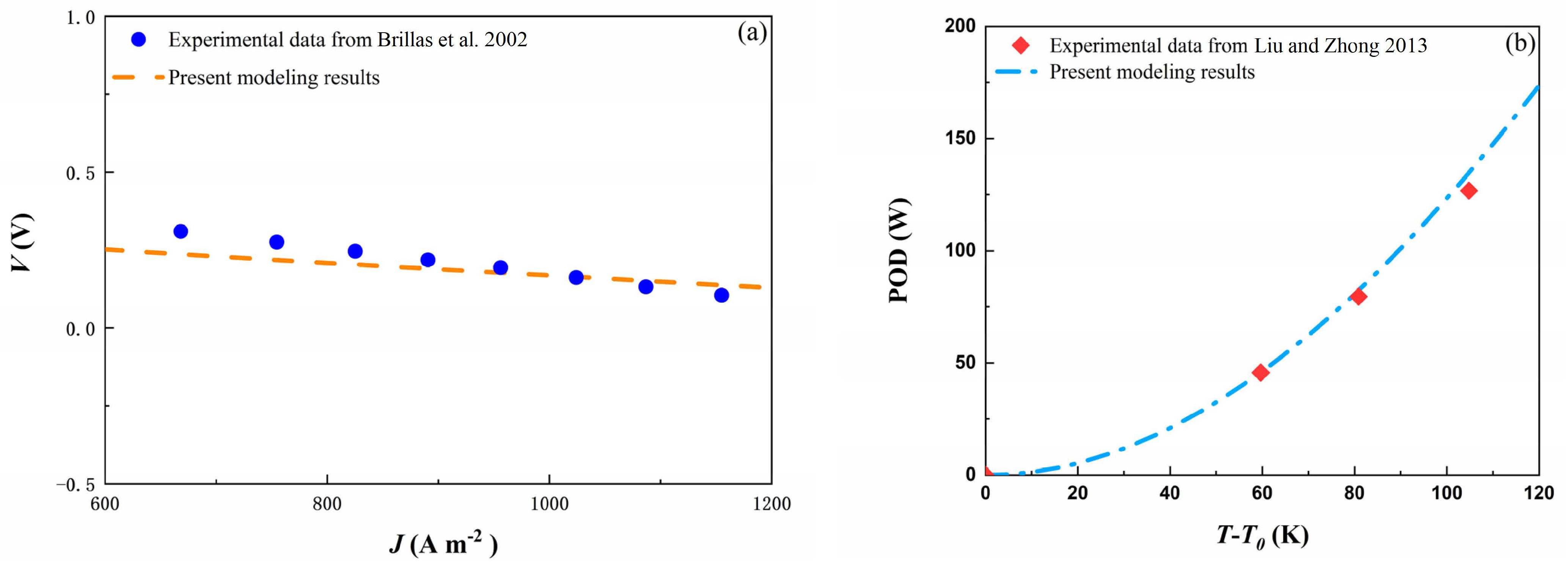
Following a thorough review of the current literature, it was discovered that no experiments have been conducted on this particular hybrid system. Therefore, the model validation for this hybrid system requires a separate validation of the AFC and ITEG models instead. Figure 2a presents a comparison between our AFC modeling results and the experimental data from Ref. [29], demonstrating that the model of the AFC closely aligns with the results from an experimental study, together with a reasonable mean relative error (MRE) [30] of 3.57%. For the ITEG model’s validation, comparisons between the results from the present modeling calculation and the data from the experimental research in Ref. [31] are depicted in Figure 2b. A reasonable MRE of 3.50% is determined, indicating the feasibility of the ITEG model. Hence, both the AFC and ITEG models can be deemed reliable. Here, the related simulation results are obtained using the various parameters in Table 1, Table 2 and Table 3.

4. The Hybrid System’s Generic Performance Characteristics and Competitiveness Assessment

By employing the various operating and design parameters in Table 1, Table 2 and Table 3, all the performances of the AFC, ITEG, and hybrid system, varying with the operating current density of the AFC, J , are obtained, as shown in Figure 3. Figure 3a displays that the PODs of the AFC P A = U c e l l J , ITEG P I = P I / A A I , and hybrid system P are first increased and then decreased with the increasing J and that this change in P I only occurs within a limited J . However, Figure 3b illustrates that, when J decreases, the EE of the AFC η A first decreases sharply and then drops slowly, and the EE of the ITEG η I initially increases and then decreases within a limited range of J , while the EE of the hybrid system η decreases sharply, following an initial increase, and then starts to decrease slowly. Moreover, the MPOD P M and corresponding EE η M P of the hybrid system are calculated as 218.04 W m−2 and 18.46%, respectively. They are, respectively, 31.19% and 54.61% larger than the MPOD P M A and corresponding EE η M P A of the AFC. In Figure 3, P M I and η M P I are, respectively, the MPOD and MEE of the ITEG, while J O , J O A , and J O I are the optimal operating current densities of the hybrid system, AFC, and ITEG, respectively.
Furthermore, the performance competitiveness of the current AFC/ITEG hybrid system is evaluated by comparing its various performance metrics with those of other AFC-based hybrid systems. This comparison sheds further light on the significance of the current hybrid system’s configuration. Upon reviewing the results in Table 4, it becomes apparent that, in terms of power generation capacity, the present hybrid system closely follows the AFC/TREC hybrid system. However, it exhibits distinct advantages over other hybrid systems, such as the AFC/TEG and AFC/IAR configurations. Therefore, based on this comprehensive comparison, it can be affirmed that the ITEG presents a competitive solution for AFC waste heat recovery and that the current AFC/ITEG hybrid system is a relatively efficient and reliable system before establishing practical AFC-based hybrid systems.

5. Results and Discussion

In this section, various parametric studies are conducted to assess the impact of key operational conditions and design parameters on the performance of the hybrid system. These include the operating temperature of the AFC, the environmental temperature, the ITEG’s geometric characteristics, and the coefficient of the spatial inhomogeneity of the ITEG. By systematically examining these parameters, we aim to gain insights into the optimal operating conditions and design configurations for maximizing this system’s efficiency and effectiveness. Unless stated otherwise, all other parameters remain consistent with the baseline case utilized for the initial performance predictions.

5.1. Effect of the Operating Temperature of the AFC

The operating temperature of the AFC T has a significant effect on the reaction kinetics and ion conductivity within the electrolyte of the AFC, and the thermoelectric effect in the ITEG is sensitive to variations in the AFC’s temperature [20]. The comprehensive impact of T on the performance of the hybrid system is displayed in Figure 4. It can be seen that the MPOD of the hybrid system P M is enhanced with the increasing T , while the corresponding EE of the hybrid system η M P also increases. Additionally, the range of the operating current density J , according to this performance improvement, gradually increases. Furthermore, the optimal operating current density J O is improved as T increases. With the escalation of J , there is a gradual widening of the range of J conducive to optimal system performance. This phenomenon indicates that higher temperatures facilitate a broader operational window within which the hybrid system can function optimally. Subsequently, the notable improvement of J O with increasing temperatures underscores the positive correlation between temperature and system efficiency.

5.2. Effect of Environmental Temperature

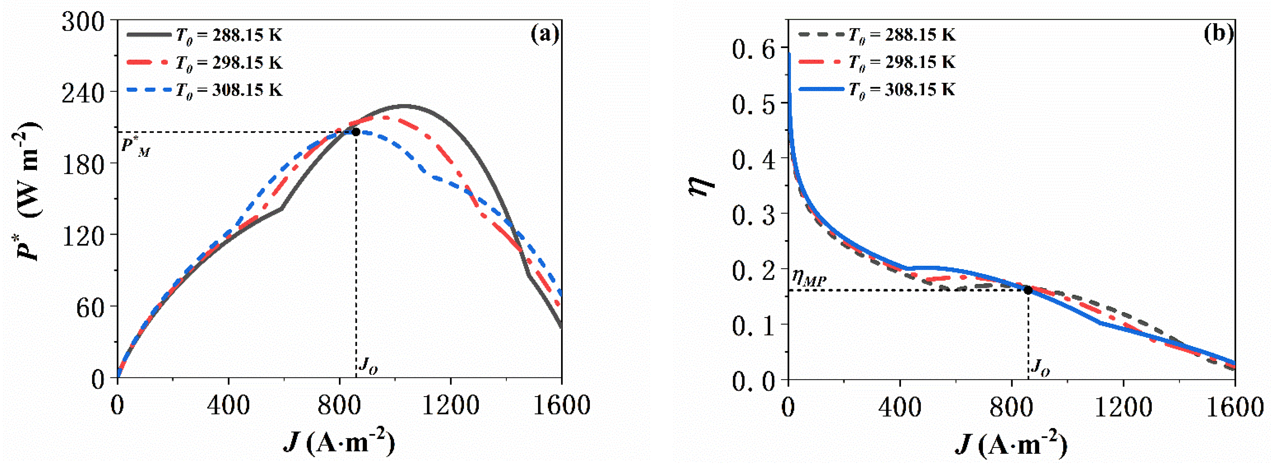
Likewise, the environmental temperature T 0 is a very critical operating condition. This affects the AFC’s degradation and reaction processes, which require proper insulation or heating [20]. Furthermore, the effectiveness of an ITEG is not solely reliant on the temperature of its high-temperature side but also hinges on the temperature of its low-temperature side, as the ITEG operates by harnessing the temperature disparity between its two sides. As illustrated in Figure 5, P M decreases with rising T 0 , while η M P increases. Additionally, the range of J for performance enhancement narrows. Moreover, the J O shifts to the left as T 0 increases. These findings highlight the complex interplay between ambient temperature and system efficiency, underscoring the importance of temperature regulation in optimizing the performance of hybrid systems.

5.3. Effect of the Geometric Characteristics of the ITEG

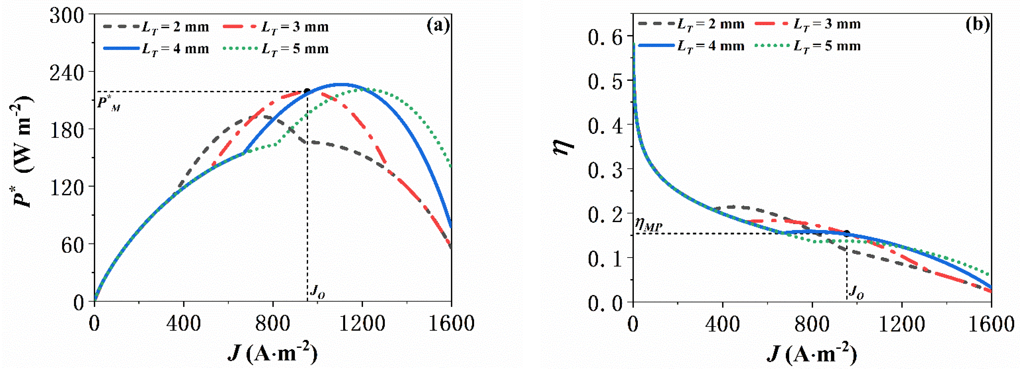
The ITEG’s geometric attributes L T are defined by the ratio of its cross-sectional area to the length of its thermoelectric elements. This ratio guides the manufacture parameters of the thermocouples within the ITEG. It determines the ITEG’s conversion efficiency because it significantly affects both the thermal conductivity and the electrical resistance within each thermoelectric element, thus controlling both the ITEG’s performance and the hybrid system’s performance. Figure 6 shows the effects of L T on the performance of the hybrid system. It can be observed that P M first improves as L T increases from 2 × 10 3 m to 4 × 10 3 m and then decreases as L T continues to increase from 4 × 10 3 m. Additionally, J O initially increases and then decreases when L T changes from 2 × 10 3 m to 5 × 10 3 m. However, η M P decreases with the increasing L T , and J O is also decreased. Typically, a larger L T , i.e., cross-sectional area-to-length ratio, leads to an elevated thermoelectric output generated by the ITEG. This is because it enables more thermocouples to participate in absorbing more heat and facilitate the thermoelectric effect more effectively. But, this increase in the ratio raises the ITEG’s electrical resistance as well, which can lower the performance of both the ITEG and the hybrid system [21]. Therefore, finding the optimal balance between maximizing thermoelectric output and minimizing electrical resistance is paramount in designing efficient ITEG-integrated hybrid systems.

5.4. Effect of the ITEG’s Coefficient of Spatial Inhomogeneity

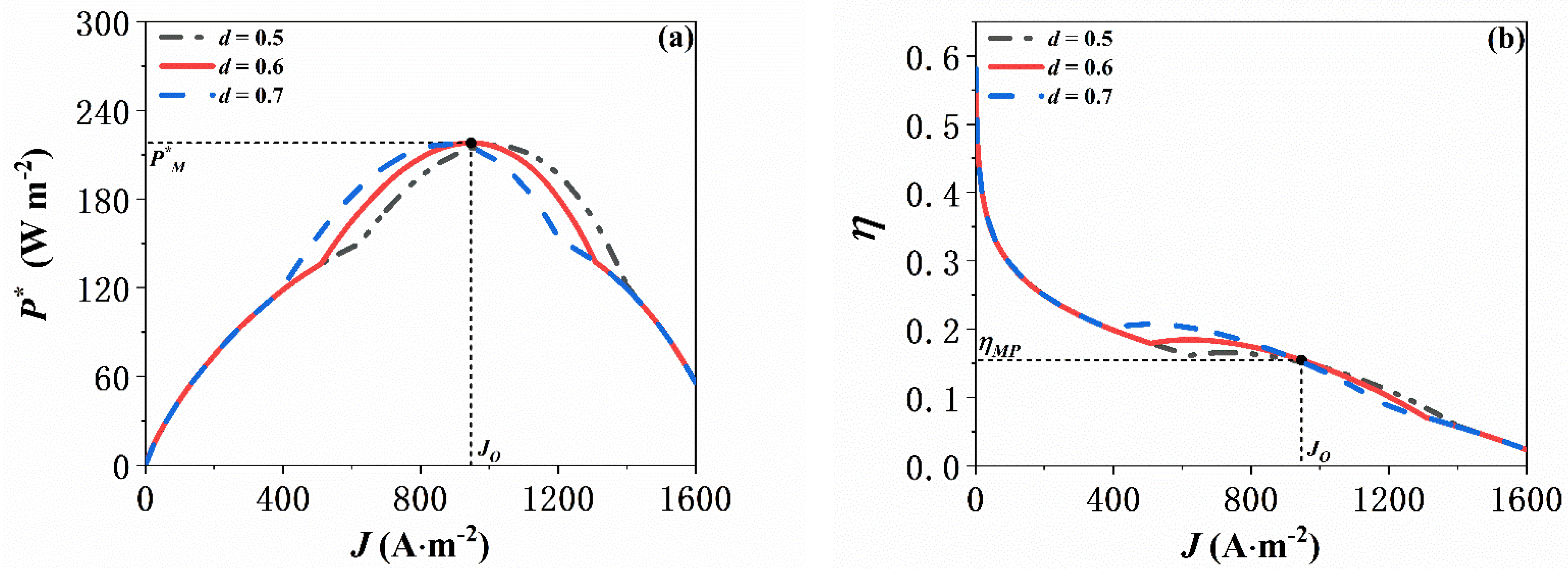
The coefficient of spatial inhomogeneity, for thermoelectric materials, d is a vital parameter that strongly affects the performance of both the ITEG and hybrid system because it describes the degree of inconsistency in the material properties and temperature distribution among the thermoelectric elements [32]. Figure 7 shows the effects of d on the performance of the hybrid system. It can be seen that the power output density of the hybrid system does not obviously improve as d increases, but its J O decreases. Additionally, η M P is mildly decreased with the increasing d due to J O shifting left. To sum up, an increasing d can improve the efficiency of the hybrid system but is not evidently contributive to its power output. In addition, a smaller spatial inhomogeneity coefficient is closer to the real conditions. Therefore, the current recommendation is that, when determining the appropriate value for this coefficient, careful consideration must be given as to whether the focus lies on improving the coupling system’s efficiency or maximizing its power output.

6. Conclusions

To maximize the utilization of the vast amount of exhaust heat produced by an AFC, a novel integrated system that integrates an ITEG with an AFC is proposed. Detailed models of both components are meticulously developed, considering various irreversible losses. In the validation of these models, mathematical expressions for the POD and EE of the hybrid system are derived. Through its comparison with a standalone AFC, we demonstrate the effectiveness of our hybrid system, revealing a significant increase in MPOD (31.19%) and a substantial improvement in its corresponding EE (54.61%). Moreover, when benchmarked against other AFC-based hybrid systems, the performance competitiveness of the presented AFC/ITEG hybrid system stands out prominently. This underscores the potential viability of the ITEG as an efficient means of recovering the waste heat from AFCs. Additionally, numerous parametric studies are conducted to investigate the hybrid system’s performance under different operational conditions and design parameters. Our findings suggest that the POD of the hybrid system can be enhanced by increasing the operating temperature of the AFC and the environmental temperature, while it can be optimized by adjusting the geometric characteristics of the ITEG. Conversely, improvements in EE are achieved by increasing the operating temperature of the AFC, as well as reducing both the environmental temperature and the ITEG’s geometric characteristics. Moreover, the coefficient of the spatial inhomogeneity within the ITEG determines the optimal operating current density of the AFC. These insights offer valuable guidance for the integration and operation of practical hybrid systems.
In the future, it will be vital to meticulously account for additional thermal effects or losses within the system to refine this system’s model comprehensively. This approach will generate a detailed quantification of the contributions of the relevant variables in performance analyses and optimizations, thereby offering more valuable insights for real-world implementation. Moreover, it is imperative to develop a corresponding experimental system or device to accurately validate the entire system’s model as a whole, rather than verifying each subsystem individually. Additionally, the integration of artificial intelligence algorithms and machine learning techniques could enhance the identification of more compatible materials for this AFC/ITEG integration system.

Author Contributions

Conceptualization, X.J. and X.Z.; methodology, C.Z.; software, M.S.; validation, C.Z. and X.Z.; formal analysis, M.S.; investigation, H.L.; data curation, H.L.; writing—original draft preparation, C.Z.; writing—review and editing, M.S., H.L. and X.Z. All authors have read and agreed to the published version of the manuscript.

Funding

This research received no external funding.

Data Availability Statement

The original contributions presented in the study are included in the article, further inquiries can be directed to the corresponding author.

Conflicts of Interest

The authors declare no conflict of interest.

References

  1. Zastempowski, M. Analysis and modeling of innovation factors to replace fossil fuels with renewable energy sources—Evidence from European Union enterprises. Renew. Sustain. Energy Rev. 2023, 178, 113262. [Google Scholar] [CrossRef]
  2. Olabi, A.G.; Wilberforce, T.; Abdelkareem, M.A. Fuel cell application in the automotive industry and future perspective. Energy 2021, 214, 118955. [Google Scholar] [CrossRef]
  3. Guo, X.; Zhang, H.; Hu, Z.; Hou, S.; Ni, M.; Liao, T. Energetic, exergetic and ecological evaluations of a hybrid system based on a phosphoric acid fuel cell and an organic Rankine cycle. Energy 2021, 217, 119365. [Google Scholar] [CrossRef]
  4. Al-Hamed, K.; Dincer, I. A novel ammonia molten alkaline fuel cell based integrated powering system for clean rail transportation. Energy 2020, 201, 117620. [Google Scholar] [CrossRef]
  5. Song, B.-Y.; Li, M.-J.; Yang, Y.-W.; He, Y.-L. Achievement of a novel porous non-noble-metal catalyst with excellent oxygen reduction reaction activity: Promoting the commercialization of alkaline fuel cells. J. Clean. Prod. 2020, 249, 119314. [Google Scholar] [CrossRef]
  6. Miyanishi, S.; Yamaguchi, T. Highly conductive mechanically robust high M w polyfluorene anion exchange membrane for alkaline fuel cell and water electrolysis application. Polym. Chem. 2020, 11, 3812–3820. [Google Scholar] [CrossRef]
  7. Zhang, X.; Rahman, E. Thermodynamic analysis and optimization of a hybrid power system using thermoradiative device to efficiently recover waste heat from alkaline fuel cell. Renew. Energy 2022, 200, 1240–1250. [Google Scholar] [CrossRef]
  8. Zhu, H.; Xiao, L.; Kuang, M.; Wang, J.; Zhang, H. Innovative use of air gap membrane distillation to harvest waste heat from alkaline fuel cell for efficient freshwater production: A comprehensive 4E study. Renew. Energy 2024, 225, 1240–1250. [Google Scholar] [CrossRef]
  9. Zhao, M.; Zhao, H.; Wu, M.; Zhang, H.; Hu, Z.; Zhao, Z. Thermodynamic analysis of a hybrid system integrating an alkaline fuel cell with an irreversible absorption refrigerator. Int. J. Electrochem. Sci. 2015, 10, 10045–10060. [Google Scholar] [CrossRef]
  10. Zhao, Q.; Zhang, H.; Hu, Z.; Li, Y. An alkaline fuel cell/direct contact membrane distillation hybrid system for cogenerating electricity and freshwater. Energy 2021, 225, 120303. [Google Scholar] [CrossRef]
  11. Zhang, X.; Cai, L.; Liao, T.; Zhou, Y.; Zhao, Y.; Chen, J. Exploiting the waste heat from an alkaline fuel cell via electrochemical cycles. Energy 2018, 142, 983–990. [Google Scholar] [CrossRef]
  12. Zhu, H.; Li, J.; Lai, C.; Zhang, H. Recycling alkaline fuel cell waste heat for cooling production via temperature-matching elastocaloric cooler. Int. J. Hydrogen Energy 2022, 47, 27124–27138. [Google Scholar] [CrossRef]
  13. Wang, M.; Ruan, J.; Zhang, J.; Jiang, Y.; Gao, F.; Zhang, X.; Rahman, E.; Guo, J. Modeling, thermodynamic performance analysis, and parameter optimization of a hybrid power generation system coupling thermogalvanic cells with alkaline fuel cells. Energy 2024, 292, 27124–27138. [Google Scholar] [CrossRef]
  14. He, J.; Li, K.; Jia, L.; Zhu, Y.; Zhang, H.; Linghu, J. Advances in the applications of thermoelectric generators. Appl. Therm. Eng. 2023, 292, 121813. [Google Scholar] [CrossRef]
  15. Wu, S.; Zhang, H.; Ni, M. Performance assessment of a hybrid system integrating a molten carbonate fuel cell and a thermoelectric generator. Energy 2016, 112, 520–527. [Google Scholar] [CrossRef]
  16. Zhao, Q.; Li, J.; Zhang, H. Synergizing perovskite solar cell and thermoelectric generator for broad-spectrum utilization: Model updating, performance assessment and optimization. Energy 2024, 289, 130008. [Google Scholar] [CrossRef]
  17. Kandil, A.; Awad, M.M.; Sultan, G.I.; Salem, M.S. Performance of a photovoltaic/thermoelectric generator hybrid system with a beam splitter under maximum permissible operating conditions. Energy Convers. Manag. 2023, 280, 116795. [Google Scholar] [CrossRef]
  18. Zhao, Q.; Zhang, H.; Hu, Z.; Hou, S. Achieving a broad-spectrum photovoltaic system by hybridizing a two-stage thermoelectric generator. Energy Convers. Manag. 2020, 211, 112778. [Google Scholar] [CrossRef]
  19. Manivannan, S.P.; Gunasekaran, D.L.; Jaganathan, G.; Natesan, S.; Muthusamy, S.M.; Kim, S.C.; Kumar, B.; Poongavanam, G.K.; Duraisamy, S. Energy and environmental analysis of a solar evacuated tube heat pipe integrated thermoelectric generator using IoT. Environ. Sci. Pollut. Res. 2022, 29, 57835–57850. [Google Scholar] [CrossRef]
  20. Yang, P.; Zhu, Y.; Zhang, P.; Zhang, H.; Hu, Z.; Zhang, J. Performance evaluation of an alkaline fuel cell/thermoelectric generator hybrid system. Int. J. Hydrogen Energy 2014, 39, 11756–11762. [Google Scholar] [CrossRef]
  21. Zhang, Y.; Liu, H.; Zhou, X.; Hu, Z.; Wang, H.; Kuang, M.; Li, J.; Zhang, H. A novel photo-thermal-electric hybrid system comprising evacuated U-tube solar collector and inhomogeneous thermoelectric generator toward efficient and stable operation. Energy 2024, 292, 130616. [Google Scholar] [CrossRef]
  22. Sobie, E.A. An introduction to MATLAB. Sci. Signal. 2011, 4, tr7. [Google Scholar] [CrossRef] [PubMed]
  23. Zhao, Q.; Guo, X.; Zhang, H.; Ni, M.; Hou, S. Performance evaluation of a novel photovoltaic-electrochemic hybrid system. Energy Convers. Manag. 2019, 195, 1227–1237. [Google Scholar] [CrossRef]
  24. Zhao, Q.; Zhang, H.; Hu, Z.; Hou, S. A solar driven hybrid photovoltaic module/direct contact membrane distillation system for electricity generation and water desalination. Energy Convers. Manag. 2020, 221, 113146. [Google Scholar] [CrossRef]
  25. Zhang, H.; Xu, H.; Chen, B.; Dong, F.; Ni, M. Two-stage thermoelectric generators for waste heat recovery from solid oxide fuel cells. Energy 2017, 132, 280–288. [Google Scholar] [CrossRef]
  26. Chen, W.-H.; Wang, C.-C.; Hung, C.-I. Geometric effect on cooling power and performance of an integrated thermoelectric generation-cooling system. Energy Convers. Manag. 2014, 87, 566–575. [Google Scholar] [CrossRef]
  27. Chen, H.; Huang, Y.; Chen, Z.; Jiang, Y. Performance analysis of the system integrating a molten carbonate fuel cell and a thermoelectric generator with inhomogeneous heat conduction. Appl. Therm. Eng. 2021, 200, 117729. [Google Scholar] [CrossRef]
  28. Manikandan, S.; Kaushik, S. The influence of Thomson effect in the performance optimization of a two stage thermoelectric generator. Energy 2016, 100, 227–237. [Google Scholar] [CrossRef]
  29. Brillas, E.; Alcaide, F.; Cabot, P.-L. A small-scale flow alkaline fuel cell for on-site production of hydrogen peroxide. Electrochimica Acta 2002, 48, 331–340. [Google Scholar] [CrossRef]
  30. Wu, S.-Y.; Zhong, Z.-H.; Xiao, L.; Chen, Z.-L. Performance analysis on a novel photovoltaic-hydrophilic modified tubular seawater desalination (PV-HMTSD) system. Desalination 2021, 499, 114829. [Google Scholar] [CrossRef]
  31. Liu, C.; Zhong Li, W. An experimental study of a novel prototype for thermoelectric power generation from vehicle exhaust. Distrib. Gener. Altern. Energy J. 2013, 28, 32–48. [Google Scholar] [CrossRef]
  32. Lu, T.; Zhou, J.; Li, N.; Yang, R.; Li, B. Inhomogeneous thermal conductivity enhances thermoelectric cooling. AIP Adv. 2014, 4, 4903547. [Google Scholar] [CrossRef]
Figure 1. Schematic diagrams of the proposed (a) hybrid system, (b) AFC, and (c) ITEG.
Energies 17 02066 g001
Figure 2. (a) Comparison of the present modeling results for the AFC and the experimental data from Ref. [29], and (b) comparison between the present modeling results for the ITEG and the experimental data from Ref. [31].
Energies 17 02066 g002
Figure 3. (a) POD of the hybrid system P and (b) EE of the hybrid system η , varying with the operating current density of the AFC J .
Energies 17 02066 g003
Figure 4. Effects of operating temperature of AFC T on (a) POD of hybrid system P and (b) EE of hybrid system η .
Energies 17 02066 g004
Figure 5. Effects of environmental temperature T 0 on (a) POD of hybrid system P and (b) EE of hybrid system η .
Energies 17 02066 g005
Figure 6. Effects of geometric characteristics of ITEG L T on (a) POD of hybrid system P and (b) EE of hybrid system η .
Energies 17 02066 g006
Figure 7. Effects of the spatial inhomogeneity coefficient of thermoelectric materials d on (a) POD of hybrid system P and (b) EE of hybrid system η .
Energies 17 02066 g007
Table 1. Equations used in the AFC model.
Anode reaction of AFC [20] H 2 + 2 O H 2 H 2 O + 2 e (1)
Cathode reaction of AFC [20] H 2 O + 0.5 O 2 + 2 e 2 O H   (2)
Overall electrochemical reaction of AFC [20] H 2 + 0.5 O 2 H 2 O + electricity + thermal   energy (3)
Maximum possible energy rate released by reactions in AFC [20] Δ H · = q · H 2 Δ h = I n e F Δ h (4)
Reversible cell potential in AFC [20] E = T T 0 Δ S   +   R T ln p H 2 p O 2 / p H 2 O Δ g f 0 n e F (5)
Charge transfer overpotential losses in AFC [20] U a c t = R T α n e F ln J c 1 exp c 2 / T (6)
Concentration overpotential losses in AFC [20] U c o n = R T α n e F ln J L J L J (7)
Ohmic overpotential losses in AFC [20] U o h m = J t e l e κ (8)
Output voltage of AFC [20] U c e l l = E U a c t U c o n U o h m (9)
PO of AFC [20] P A = U c e l l I (10)
EE of AFC [20] η A = P A Δ H · (11)
Table 2. The physical properties of the thermoelectric material Bi 2 Te 3 , where T m = T + T 0 / 2 represents the average temperature of the TE [28].
ParameterSymbolExpression
Seebeck coefficient ( V   K 1 ) α T 2 × 22224.0 + 930.6 T m 0.9905 T m 2 × 10 9
Electrical resistivity ( Ω   m ) ρ p = ρ n 5115.0 + 163.4 T m + 0.6279 T m 2 × 10 10
Thermal conductivity (W K−1 m−2) κ p = κ n 62605.0 277.7 T m + 0.4131 T m 2 × 10 4
Geometric characteristics (mm) L T 2.96
Table 3. The parameters used in the hybrid system model.
ParameterValue
F ( C   mol 1 )96,485 [20]
n e 2 [20]
R ( J   mol 1   K 1 )8.314 [20]
P H 2 ( atm )0.97 [20]
P H 2 O ( atm )1 [20]
P O 2 ( atm )1 [20]
J L ( A   m 2 )2000 [20]
c 1 ( A   m 2 )174,512 [20]
c 2 ( K )5485 [20]
t e l e ( m )0.001 [20]
T ( K )353 [20]
T 0 ( K )298.15 [20]
χ 100% [20]
A L ( m 2 ) 9 × 10 4 [20]
K L ( W   m 2   K 1 )20 [20]
d 0.5 [21]
A A I ( m 2 )1 [21]
n 3000 [21]
Table 4. Performance comparisons of available hybrid systems based on AFCs.
Performance Indexes Output   Power   Density   at   AFC s   Maximum   Output   Power   Density ,   W   m 2 Energy Efficiency at AFC’s Maximum Output Power DensityImprovement in Output Power DensityImprovement in Energy Efficiency
Hybrid Systems
AFC/TEG hybrid system [20]204.4813.10%23.03%10.08%
AFC/TREC hybrid system [11]382.2615.80%52.90%184.68%
AFC/IAR hybrid system [9]173.0613.13%8.09%9.97%
AFC/ITEG hybrid system218.0418.46%31.19%54.61%
Disclaimer/Publisher’s Note: The statements, opinions and data contained in all publications are solely those of the individual author(s) and contributor(s) and not of MDPI and/or the editor(s). MDPI and/or the editor(s) disclaim responsibility for any injury to people or property resulting from any ideas, methods, instructions or products referred to in the content.