Article

Characteristics of High-Pressure Injection Pump Operated with Renewable Fuel for Diesel Engines

Dipartimento di Ingegneria Industriale, Elettronica e Meccanica DIIEM, Università degli Studi Roma TRE, via della Vasca Navale, 79, 00146 Rome, Italy
*
Author to whom correspondence should be addressed.
Energies 2024, 17(7), 1656; https://doi.org/10.3390/en17071656
Submission received: 20 February 2024 / Revised: 23 March 2024 / Accepted: 25 March 2024 / Published: 29 March 2024

Abstract

:
The use of renewable fuels for internal combustion engines marks a significant stride towards sustainability in transportation and power generation. Ensuring the compatibility of these fuels with existing diesel engines and infrastructure is paramount for a smooth transition. Diesel engines capable of harnessing the advantages of alternative fuels without extensive modifications offer a pragmatic approach to sustainable power for vehicles and industries. This article investigates the impact of carbon-neutral renewable fuel types (hydrogenated vegetable oils, or HVOs, and biodiesel) on the operation of a high-pressure injection pump, focusing on rotational speed and delivery pressure as key parameters. Our investigation, based on pump operating cycle analysis and volumetric efficiency measurements, aimed to investigate to what extent shaft speed and fuel type influence pump performance. Hydrogenated carbon-neutral fluids (HVOs) demonstrate adequate hydraulic capabilities compared to conventional fossil fuels. The findings underscore that while the fluids under consideration vary in viscosity and compressibility modulus, it is the compressibility modulus that predominantly affects the pump’s operation cycle. Diesel (fossil) fluid exhibits intermediate characteristics compared to hydrogenated fossil diesel fluids and biodiesel. The differences in terms of volumetric efficiency are finally reported, showing that hydrogenated carbon-neutral fluids do not significantly hinder the pump’s flow rate transfer capability.

1. Introduction

The adoption of alternative fuels that reduce the carbon footprint of internal combustion engines represents a pivotal advancement in sustainability in transportation [1] and power generation [2]. The compatibility of new fuels with existing engines and distribution infrastructure is fundamental to ensure a seamless transition [3]. Engines that harness the benefits of alternative fuels without compromising aftertreatment system compatibility and without necessitating extensive modifications (such as injection strategy/combustion recalibration or the substitution of injection system components) provide a pragmatic pathway toward sustainable power for vehicles and industry [4,5]. This adaptability contributes to the feasibility and scalability of alternative fuel adoption across different automotive and industrial platforms. Thus, the adoption of alternative and green fuels stands as a progressive strategy to substantially reduce the environmental impact of engine operation [6,7,8]. In some engineering fields, such as lubrication and fluid power [9], alternative fluids are being tested to progressively reduce and replace fossil materials. This transition towards green sources not only aligns with environmental goals but also signifies a fundamental step in fostering more sustainable and resilient transportation [10] and industrial ecosystems.
Diesel engines inherently exhibit a superior efficiency due to their high compression ratios [11]. This efficiency translates into a better fuel economy and reduced carbon emissions per unit of produced energy. Hence, combining diesel technology and the adoption of renewable fuels is regarded as a convenient choice to minimize the environmental footprint of internal combustion engines (carbon footprint and pollutant emissions).
The common rail high-pressure injection system plays a fundamental role in advanced diesel engines, aiming for optimal combustion and the effective control of pollutant formation. It serves as a cornerstone in the realm of advanced diesel engines, primarily due to its pivotal role in achieving two critical objectives: optimal combustion and the effective control of pollutant formation. This system controls the injection process by precisely delivering fuel to the combustion chamber, ensuring a properly atomized spray pattern. Moreover, the precise control over fuel injection timing and duration offered by the common rail system allows the combustion process to be finely tuned, optimizing performance and minimizing the emissions of pollutants such as nitrogen oxides (NOx) and particulate matter (PM). On one hand, research efforts are being devoted to improving injector behavior [12], with particular attention paid to advanced nozzle layouts operating under realistic conditions [13]. On the other hand, the high-pressure pumps exert a substantial demand on engine power for their operation, making their overall efficiency a critical parameter in determining the energy loss during fuel injection. This power requirement must be accurately considered when configuring injection strategies, seeking to strike the necessary trade-off between engine fuel efficiency and precise combustion control [14]. The overall efficiency of the high-pressure pump, which is expressed as the product of the volumetric efficiency and torque efficiency, is dependent on its operating conditions, such as the injection pressure level, pump shaft speed, and fuel properties. Investigating these factors is essential to optimizing the injection strategy by taking the pump efficiency into account. According to [15], the fuel type has a significant influence on the performance of the high-pressure pump. It has been observed that the pump behavior reflects the mechanical characteristics of fuels. Indeed, the viscosity and bulk modulus affect the pump volumetric efficiency and torque efficiency, since they influence lubrication, leakages, and flow rate reduction due to compressibility. From this perspective, blending fuels with different properties, such as fossil diesel and biodiesel, offers the chance to increase the overall pump efficiency, as reported in [16].
Besides diesel–biodiesel blends, fossil-free fuels have been recently introduced to the market. These fuels are known as hydrogenated or hydrotreated vegetable oils (HVOs) and are obtained from vegetable oils through a hydrotreatment process [17,18]. Biodiesel, typically produced through transesterification, utilizes vegetable oils or animal fats. However, it may have a higher oxidation susceptibility and storage instability. On the other hand, HVOs involve the reaction of oils or fats with hydrogen, resulting in a fuel with an enhanced stability and lower susceptibility to oxidation. HVOs boast a lower freezing point, enhancing their suitability across a diverse spectrum of environmental conditions. Both fuels play a relevant role in curbing greenhouse gas emissions, providing renewable alternatives to traditional diesel. The selection between them is, in general, dependent on precise application requirements, as well as compliance with environmental considerations and regulations. Thus, specific experimental investigations would provide precious information about their influence on pump behavior.
In [19], a specific review of the scientific literature on high-pressure diesel injection pumps is reported. The contributions cover many topics that are typically encountered when high-pressure hydraulic machines are investigated, such as tribology, noise, the micro-motion of the piston cylinder pair, and efficiency. Real-time pressure measurements within the piston working chamber provide the means to discern the suction, compression–expansion, and delivery phases of the fluid. The fuel properties distinctly affect the pumping phases, enabling straightforward comparative analyses and highlighting the behavior of the cylinder–piston pair, valve throttling, leakages, and other non-idealities that influence pump operation. The current investigation aims to integrate the in-depth analysis of the pump operation cycle with the experimental characterization of the pump volumetric efficiency.
As is thoroughly reported in the next section, after completing the analysis of a single-piston common rail pump with a reference diesel fuel, our attention was directed towards alternative fuels (pure biodiesel and two HVO fuels), illustrating how fluids impact pump operation.

2. Materials and Methods

2.1. Pump Operation Cycle and Volumetric Efficiency

The influence of fuels on pump operation is investigated through work cycle analysis. The work cycle is built in terms of pressure–volume diagrams. The pressure in the piston working chamber is measured and related to the piston stroke, which is dependent on the pump shaft angular position. As reported in the next paragraph, the high-pressure pump under investigation is a single-piston unit, driven by a roller–cam pair, with two strokes per shaft revolution. The angular position of the pump shaft is monitored with an incremental quadrature encoder (1800 pulses per revolution). As a first investigation step, the piston kinematics are measured as a function of the pump shaft angular position. With each pulse of the encoder, the cam profile is measured through a digital comparator with 1 µm resolution. The signals coming from encoder and comparator are reported to the DAQ system, driving the pump shaft at very low speed (1 RPM). Figure 1 reports the volume of pump chamber and the cam profile versus pump shaft angle.
Once the volume of the working chamber is related to the pump shaft position, a pressure measurement is achieved through a piezoresistive pressure transducer that reaches the working chamber. Such a transducer undergoes a wide range of pressure variations, from the boost level (4 bar) up to the maximum level (1800 bar). Another, narrow-range, piezoresistive pressure transducer is placed immediately upstream of the pump inlet valve. A third transducer reads the pressure in the delivery ambient (rail). All pressure signals are acquired simultaneously and referred to a certain angular position of the pump shaft, which is provided by a dedicated encoder output channel.
Alongside the operating cycle of the pump, the pump volumetric efficiency is measured (Equation (1)).
η v = Q d e l Q t h = Q d e l n V d i s p l
Q d e l is the volumetric flow rate that is found at pump delivery port, whereas Q t h is the theoretical flow rate, defined as n V d i s p l . V d i s p l is the pump capacity, and n is the pump shaft speed. Here, Q d e l is computed through Equation (2), where Q i n l e t and Q r e t u r n are the measured flow rates at pump inlet and at pump return lines, respectively.
Q d e l = Q i n l e t Q r e t u r n
Measurements are affected by the error ε (Equation (3)), consisting of systematic errors ε s and random errors ε c .
ε = ε s + ε c
Systematic errors are predictable and can be reduced, while random errors contribute to the variability of measurements and are typically mitigated through statistical methods.
Here, each signal from a sensor or instrument is reported to the data acquisition system, and then the quantities are measured at different times under the same operating conditions and acquired. The data acquisition system is programmed to average multiple measurements to reduce random errors and improve the precision of the estimate, according to the following procedure:
-
from the acquired measurements, at least 64 averages x ¯ i are calculated (according to [20], the minimum value for averaging a sample of measurements is 30);
-
X ¯ , the average of the mean values x ¯ i , is calculated;
-
the deviations from the mean value, δ X i = x ¯ i X ¯ , are determined;
-
the standard deviation s = i = 1 N δ X i 2 N N 1 is calculated, where N = 64 indicates the number of partial acquisitions.
The uncertainty σ X ¯ is calculated according to Equation (4).
σ X ¯ = 2 · s
With the above procedure, the uncertainty of the individual quantity, X, under consideration is determined (Equation (5)):
X = X ¯ ± σ X ¯
The uncertainty of a quantity that depends on a product, such as f = x y , is given by Equation (6):
σ F ¯ F ¯ = σ X ¯ X ¯ 2 + σ Y ¯ Y ¯ 2 ,
where F ¯ is given by the ratio of the mean quantities (Equation (7)).
F ¯ = X ¯ Y ¯
According to [21], the uncertainty for shaft position and angular velocity is negligible. The uncertainty for pump displacement is the same as that for flow rate because it is derived according to Equation (2). Thus, the uncertainty for pump volumetric efficiency is given by Equation (8)
σ η V = σ Q Q ¯ 2 + σ V d i s p V d i s p ¯ n 2 ± 0.002
and the volumetric efficiency is written as Equation (9):
η V = η V ¯ ± 0.002

2.2. Experimental Setup

The experimental setup is implemented at the Fluid Power Laboratory (Industrial, Electronic and Mechanical Engineering Department, Roma TRE University). The pump model investigated here is the Bosch CP4.1 [22], typically adopted for light- and medium-duty diesel engines. Table 1 reports the relevant pump specification.
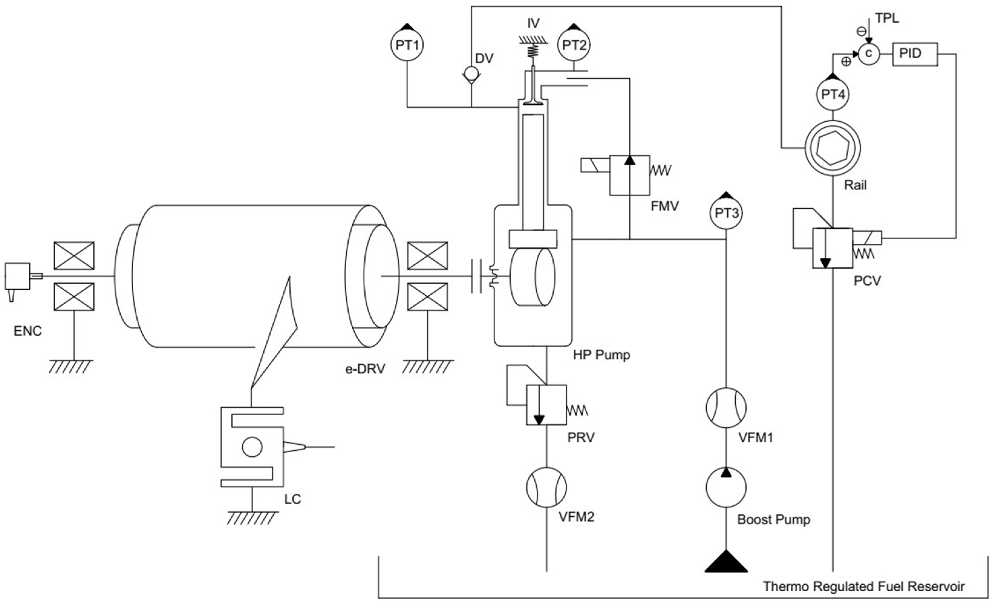
Figure 2 illustrates the mechanical–hydraulic configuration of the system. Pump shaft speed is imposed, regardless of the rail pressure conditions, by the electric drive (e-DRV). In the rail tube (Rail), pressure regulation is based on PID control of the pressure control valve (PCV). The boost pump supplies the high-pressure pump. The pressure relief valve (PRV), situated in the HP pump body, governs the fuel pressure upstream of the flow control valve (FMV). The tested fuel is delivered by a parallel-flow fluid handling system that provides thermal regulation and filtration within the reservoir. Flow rates are measured through volumetric flow meters on pump inlet line (VFM1) and on pump return line (VFM2). A rotary encoder (ENC) is used to measure the speed and the angular position of the pump shaft. The pressure transducers detect the piston working chamber pressure (PT1), the inlet pressure (PT2), the boost pressure (PT3), and the rail pressure (PT4).
All the instrumentation signals are sent to a multi-channel DAQ system. The data acquisition of all the signal lines is simultaneous, and each signal is synchronized to the reference angular position given by the rotary encoder (ENC). Pump operating cycles are built by averaging 64 cycles. Table 2 reports the relevant specifications of DAQ system and instrumentation.

2.3. Tested Fluids

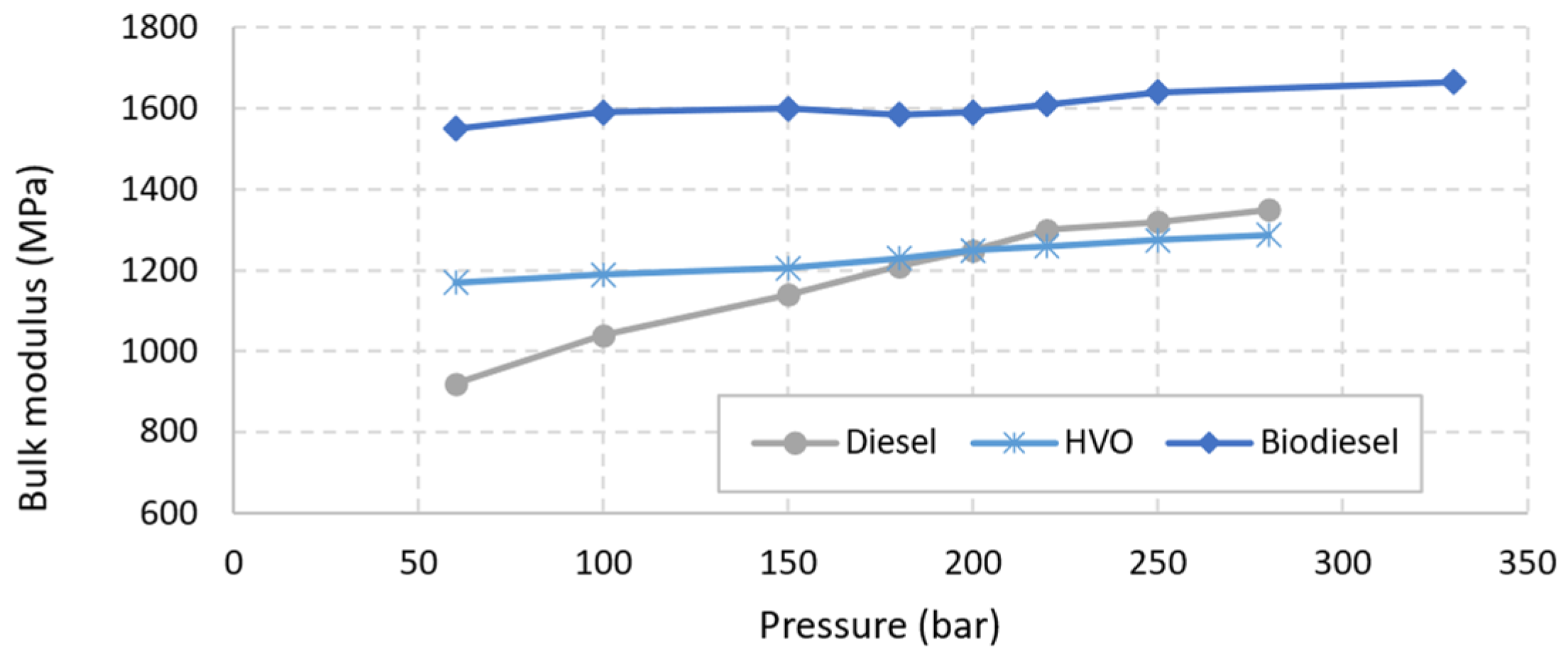
As mentioned in the introduction, here, the commercial diesel fuel “ENI Diesel+” is considered the reference fluid. The alternative tested fluids are represented by three fully renewable fuels. The first belongs to the FAME category, and it is obtained through the transesterification of used cooking oils and animal fats from industry waste. The other two fuels belong to the HVO category. They are obtained by hydrotreating renewable raw vegetal materials. Table 3 summarizes their features. Information about density and viscosity are derived from the producers’ datasheets, whereas information on bulk modulus is found in the literature [23,24,25] and reported in Figure 3, according to [24].

2.4. Test Cases

The influence of fuel type is investigated at low (L), medium (M), and high (H) pressure levels. Despite the maximum injection pressure reaching very high levels (2500 bar and beyond), the considered pressure test points in the current investigation are intended to represent the pressure levels expected in real drive conditions. Concerning the two considered speed conditions, the former is in the range of the maximum torque of the engines (1500 RPM); the latter is typically meaningful at medium/high engine power (3000 RPM). Table 4 reports the test conditions, namely, 6 operation points for each fuel type (24 in total).

3. Results and Discussion

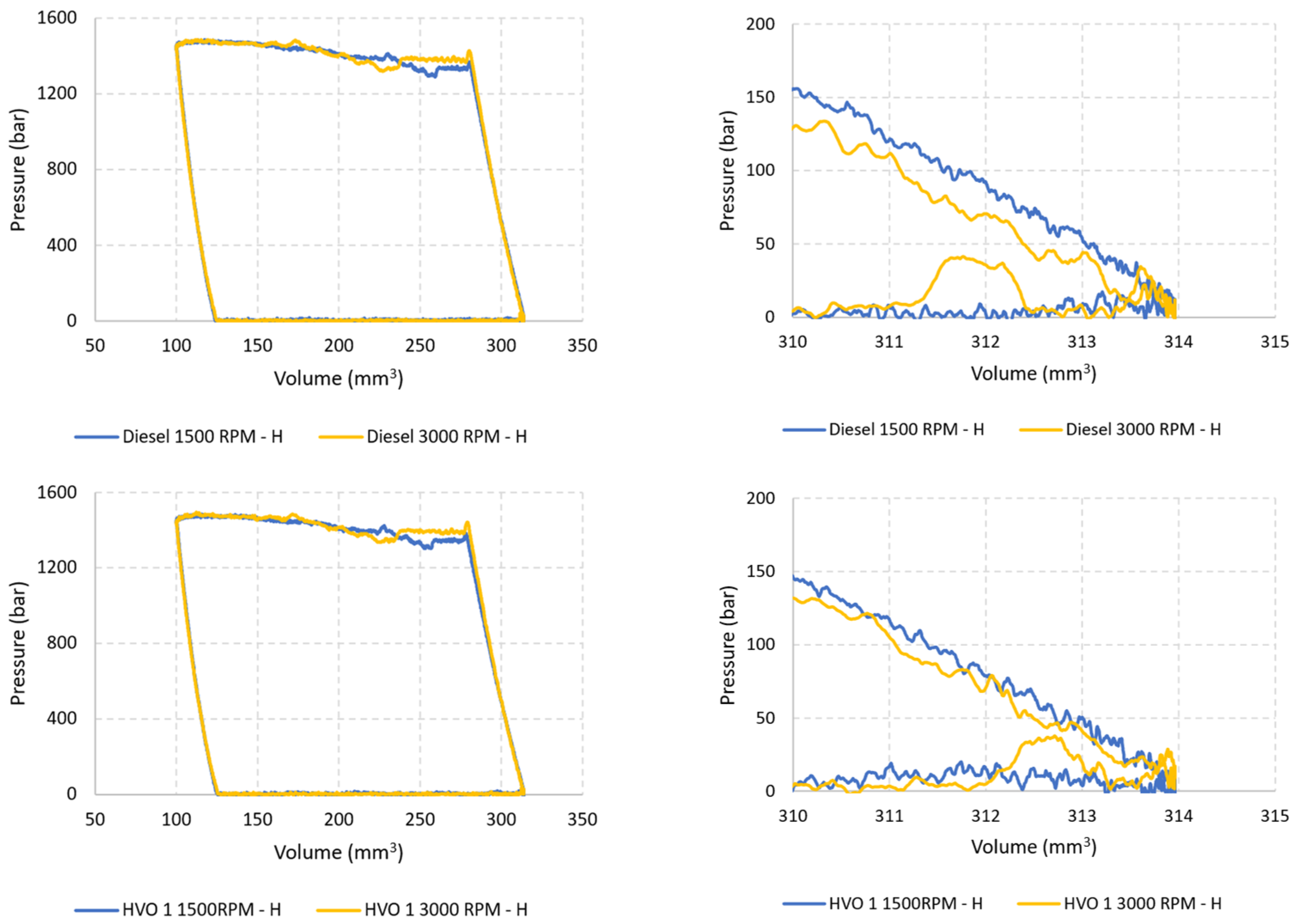
Figure 4 presents diagrams of the pump internal pressure at 1500 RPM. The internal pressure is plotted against the piston working chamber volume for the three pressure levels (L, M, and H) and the four considered fuels. The results are organized in the figure by displaying the complete pump operation cycles in the left column, while cycle details or subphases are shown on the right. Pressure–volume (p-V) diagrams highlight the pump behavior throughout its operating cycle, depending on the fuel. Each fuel type and pressure level produces its own distinctive curve, reflecting how the pump’s internal pressure varies with changes in the piston working chamber volume. The left column in figure shows the complete cycle diagrams. The right column provides more detailed information about the late suction phase and the compression (or early compression) phase, helping to highlight key events or transitions.
The pump sensitivity to different fluids is primarily evident in the compression and expansion phases. Fluids with a higher compressibility modulus enable the pump to initiate the delivery phase earlier, thereby enhancing its fluid transfer capability. Additionally, the graphs illustrate that both hydrogenated fuels under consideration (HVO 1 and HVO 2) induce very similar operational modes in the pump (grey line is under yellow line). Specifically, hydrogenated fuels lead to a moderate yet noteworthy extension of the compression phase, resulting in a reduction in the amplitude of the delivery phase. The fluid that achieves the shortest compression phase is WCO, indicated by the steepest trace of the compression phase. Diesel fuel exhibits an intermediate behavior between HVO and WCO. In all cases, the concavity of both the compression and expansion phases is evident, aligning with the increasing function of the compressibility modulus of liquids with pressure [25]. The characteristics of the delivery phase remain consistently similar across different fluids.
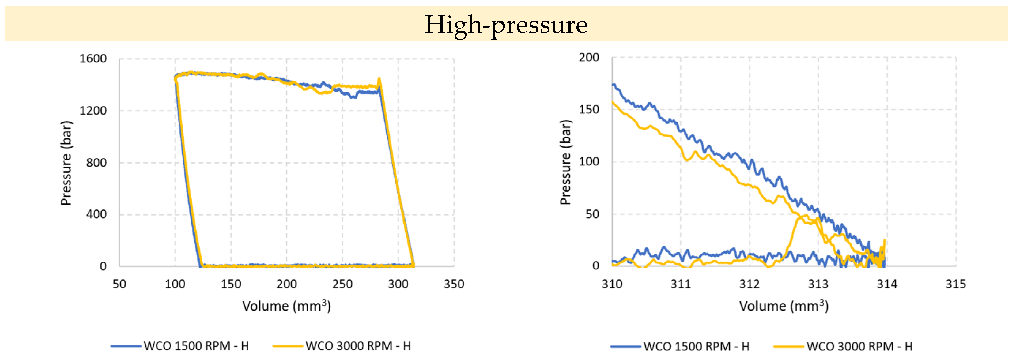
Figure 5 shows the working diagrams of the pump at 3000 RPM. The impact of fluids on the pump behavior resembles that observed at 1500 RPM, with the diagrams of the two HVO fuels superimposed, and the diesel diagram positioned between HVO and WCO. However, it is noteworthy that at 3000 RPM, the pump exhibits some irregularities towards the end of the intake phase. Upon closer inspection of the end of the suction phase (Figure 6), significant deviations in pressure trends are observed compared to the set admission pressure of 4 bar. The pressure peaks highlighted in Figure 6 (right) occur during the final stages of intake, when the volume of the working chamber is still increasing. In such instances, it is conceivable that these pressure peaks stem from communication with the delivery environment, possibly due to the imperfect sealing of the delivery valve or its oscillation/vibrations. This phenomenon is present across all three pressure levels and never appears at low speed.
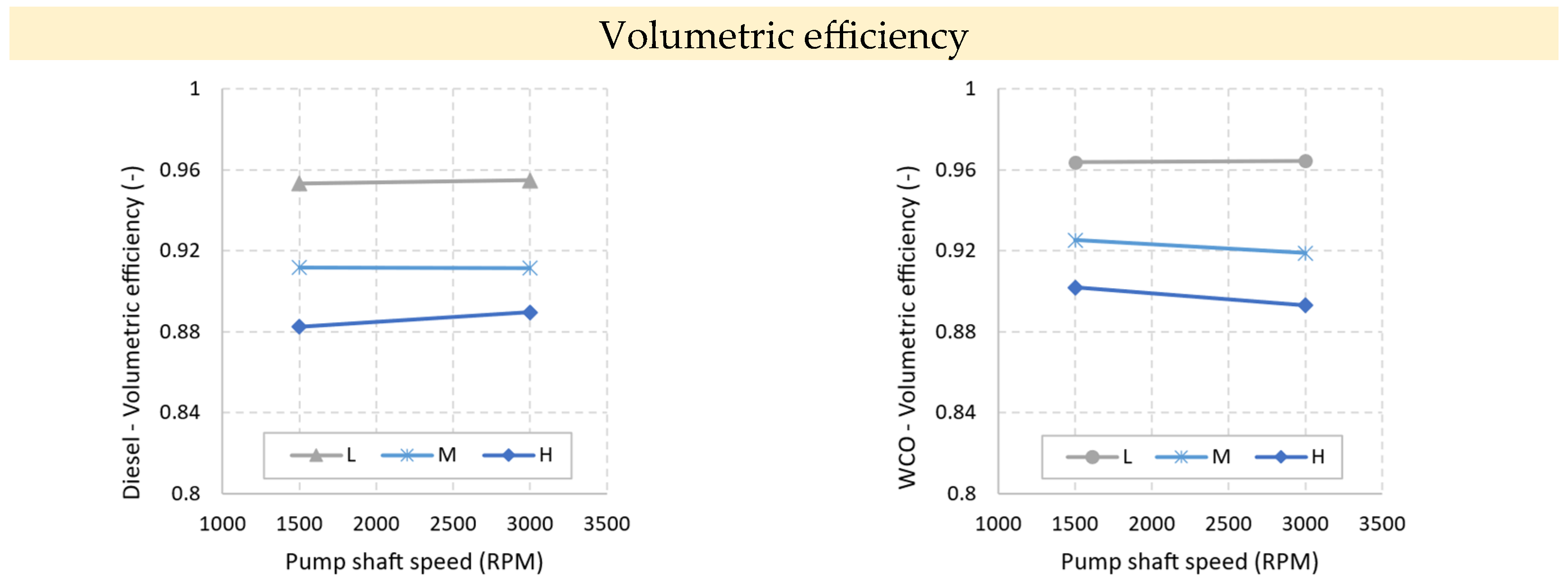
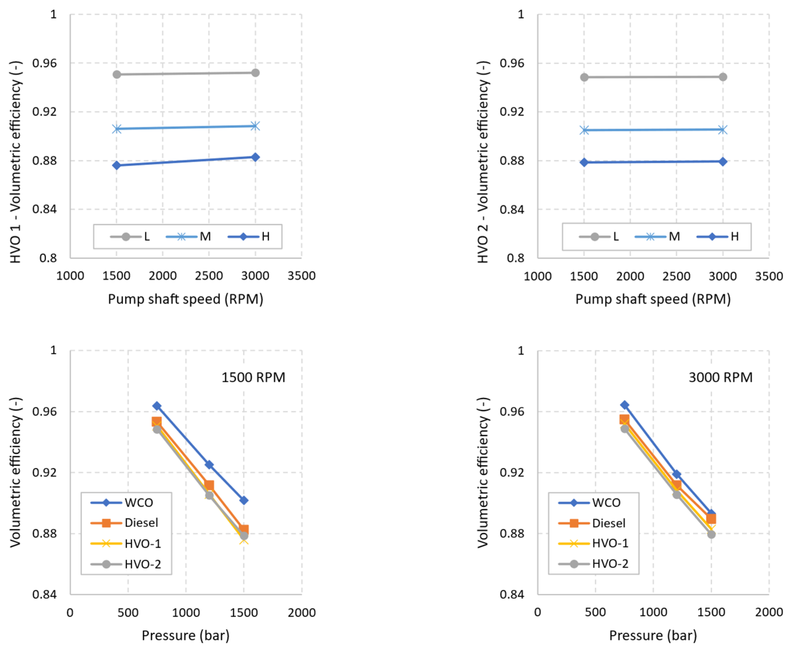
Figure 7 illustrates the trends in volumetric efficiency measured at each investigated operation point, highlighting the influence of the pressure level and pump shaft speed. Notably, as the pressure increases, there is a significant decrease in efficiency (the drop is in the order of seven percentage points from the lowest to highest pressure level). These findings align with the pressure–volume diagrams previously presented, underscoring that the pump fluid transfer capability primarily hinges on the compressibility modulus of the fluid. While the speed dependence is of secondary importance, it remains perceptible. Specifically, at high pressures, the volumetric efficiency of the pump operating with fluids characterized by lower viscosity (such as diesel, HVO 1, and HVO 2) tends to increase with speed. Conversely, when operating with WCO fluid, the pump tends to be penalized at high speeds, despite WCO consistently yielding the highest volumetric efficiency under all conditions. This observation suggests that when the pump speed increases, it does not necessarily result in a higher volumetric efficiency due to leakage reduction. Using fluids with relatively high viscosity, such as WCO, the increased speed leads to increased losses that affect the fluid transfer process.

4. Conclusions

The behavior of the high-pressure pump was analyzed by combining pressure–volume diagrams with volumetric efficiency measurements. It was found that the analysis of pump performance allowed us to distinguish the type of fuel being processed. Through investigations of each fluid, the effects of the pump’s two primary operating parameters—rotation speed and delivery pressure—were elucidated. The analysis revealed that speed dependence was moderate. This conclusion was drawn from the combined examination of pressure trends within the pump’s working chamber and volumetric efficiency values, indicating that rotation speed has little influence on fluid transfer (the differences were in the order of 1 percentage point). In contrast, the dependence on delivery pressure was much more pronounced. Passing from the lowest- to the highest-pressure level caused a 7-percentage-point reduction in volumetric efficiency. While the fluids under consideration varied in viscosity and compressibility modulus, it was the compressibility modulus that predominantly affected the pump’s fluid transfer ability. Diesel (fossil) fluid exhibited intermediate characteristics compared to hydrogenated fossil diesel fluids and biodiesel. Notably, since the differences in terms of volumetric efficiency were limited to 1-percentage point among the tested fuels, hydrogenated carbon-neutral fluids allowed for performance levels that did not significantly hinder the pump’s flow rate transfer capability.

Author Contributions

F.P. and O.C. conceived and organized the work; O.C., F.P. and F.V. designed the investigations, analyzed the data, and wrote the article; F.P. and F.V. performed experiments. All authors have read and agreed to the published version of the manuscript.

Funding

This research received no external funding.

Data Availability Statement

The original contributions presented in the study are included in the article, further inquiries can be directed to the corresponding author.

Acknowledgments

The authors acknowledge the support of Jonas Matijošius, from the Department of Automobile Engineering, Faculty of Transport Engineering, Vilnius Gediminas Technical University, J. Basanavičiaus Str. 28, Vilnius, LT-03224, Lithuania and the support of DP Lubrificanti S.p.a., 16-04011 Aprilia (LT) IT for providing the WCO biodiesel used in this research.

Conflicts of Interest

The authors declare no conflicts of interest.

References

  1. Hua, Y. Research progress of higher alcohols as alternative fuels for compression ignition engines. Fuel 2024, 357, 129749. [Google Scholar] [CrossRef]
  2. Yadav, J.; Deppenkemper, K.; Pischinger, S. Impact of renewable fuels on heavy-duty engine performance and emissions. Energy Rep. 2023, 9, 1977–1989. [Google Scholar] [CrossRef]
  3. Betgeri, V.; Bhardwaj, O.P.; Pischinger, S. Investigation of the drop-in capabilities of a renewable 1-Octanol based E-fuel for heavy-duty engine applications. Energy 2023, 282, 128811. [Google Scholar] [CrossRef]
  4. Khan, M.Z.A.; Khan, H.A.; Ravi, S.S.; Turner, J.W.; Aziz, M. Potential of clean liquid fuels in decarbonizing transportation—An overlooked net- zero pathway? Renew. Sustain. Energy Rev. 2023, 183, 113483. [Google Scholar] [CrossRef]
  5. Chiatti, G.; Chiavola, O.; Recco, E.; Palmieri, F. Soot Particles Experimental Characterization during Cold Start of a Micro Car Engine. Energy Procedia 2016, 101, 662–669. [Google Scholar] [CrossRef]
  6. Samanta, S.; Sahoo, R.R. Waste Cooking (Palm) Oil as an Economical Source of Biodiesel Production for Alternative Green Fuel and Efficient Lubricant. Bioenergy Res. 2021, 14, 163–174. [Google Scholar] [CrossRef]
  7. Amran, N.A.; Bello, U.; Hazwan Ruslan, M.S. The role of antioxidants in improving biodiesel’s oxidative stability, poor cold flow properties, and the effects of the duo on engine performance: A review. Heliyon 2022, 8, e09846. [Google Scholar] [CrossRef] [PubMed]
  8. Jablonický, J.; Feriancová, P.; Tulík, J.; Hujo, L.; Tkáč, Z.; Kuchar, P.; Tomić, M.; Kaszkowiak, J. Assessment of technical and ecological parameters of a diesel engine in the application of new samples of biofuels. J. Mar. Sci. Eng. 2022, 10, 1. [Google Scholar] [CrossRef]
  9. Pochi, D.; Fanigliulo, R.; Grilli, R.; Fornaciari, L.; Bisaglia, C.; Cutini, M.; Brambilla, M.; Sagliano, A.; Capuzzi, L.; Palmieri, F.; et al. Design and Assessment of a Test Rig for Hydrodynamic Tests on Hydraulic Fluids. In Lecture Notes in Civil Engineering; Springer: Cham, Switzerland, 2020; Volume 67, pp. 419–429. [Google Scholar]
  10. Sonthalia, A.; Kumar, N. Hydroprocessed vegetable oil as a fuel for transportation sector: A review. J. Energy Inst. 2019, 92, 1–17. [Google Scholar] [CrossRef]
  11. Da Costa, R.B.R.; Coronado, C.J.R.; Hernández, J.J.; Malaquias, A.C.T.; Flores, L.F.V.; de Carvalho, J.A. Experimental assessment of power generation using a compression ignition engine fueled by farnesane—A renewable diesel from sugarcane. Energy 2021, 233, 121187. [Google Scholar] [CrossRef]
  12. Chiavola, O.; Palmieri, F. On a Modified VCO Nozzle Layout for Diesel Common Rail Injectors under Actual Needle Displacement. Energy Procedia 2017, 126, 1027–1034. [Google Scholar] [CrossRef]
  13. Jin, T.; Wang, C.; Moro, A.; Roell, A.; Wu, X.; Luo, F. The influence of needle eccentric motion on injection and spray characteristics of a two-layered eight-hole diesel injector. Proc. Inst. Mech. Eng. Part D J. Automob. Eng. 2023, 09544070231179779. [Google Scholar] [CrossRef]
  14. Stroia, B. A Compact and Efficient Modular High Pressure Diesel Common Rail Pump Platform for Future Diesel Engine Applications. In SAE Technical Papers; SAE International: Warrendale, PA, USA, 2023. [Google Scholar]
  15. Cavallo, D.M.; Chiavola, O.; Frattini, E.; Palmieri, F. On the Modeling of Single-Piston CR Pump. In SAE Technical Papers; SAE International: Warrendale, PA, USA, 2022. [Google Scholar]
  16. Cavallo, M.; Frattini, E.; Palmieri, F. Fuel Influence on Single-Piston Common Rail Pump Performance. In SAE Technical Papers; SAE International: Warrendale, PA, USA, 2021. [Google Scholar]
  17. Trzaska, J.; Hernández, J.J.; Boehman, A.L. The effect of 1-octanol blending on the multi-stage autoignition of conventional diesel and HVO fuels. Fuel 2023, 354, 129386. [Google Scholar] [CrossRef]
  18. Preuß, J.; Munch, K.; Denbratt, I. Performance and emissions of renewable blends with OME3-5 and HVO in heavy duty and light duty compression ignition engines. Fuel 2021, 303, 121275. [Google Scholar] [CrossRef]
  19. Chiavola, O.; Frattini, E.; Lancione, S.; Palmieri, F. Operation Cycle of Diesel CR Injection Pump via Pressure Measurement in Piston Working Chamber. Energies 2021, 14, 5385. [Google Scholar] [CrossRef]
  20. Hughes, I.; Hase, T. Measurements and Their Uncertainties: A Practical Guide to Modern Error Analysis; OUP: Oxford, UK, 2010. [Google Scholar]
  21. Manring, N.D. Measuring pump efficiency: Uncertainty considerations. J. Energy Resour. Technol. Trans. ASME 2005, 127, 280–284. [Google Scholar] [CrossRef]
  22. Bosch, R. Automotive Handbook, 10th ed.; Wiley: Hoboken, NJ, USA, 2019; p. 1750. [Google Scholar]
  23. Payri, R.; Salvador, F.J.; Gimeno, J.; Bracho, G. The effect of temperature and pressure on thermodynamic properties of diesel and biodiesel fuels. Fuel 2011, 90, 1172–1180. [Google Scholar] [CrossRef]
  24. Lapuerta, M.; Agudelo, J.R.; Prorok, M.; Boehman, A.L. Bulk modulus of compressibility of diesel/biodiesel/HVO blends. Energy Fuels 2012, 26, 1336–1343. [Google Scholar] [CrossRef]
  25. Kim, T.; Boehman, A.L. Experimental Measurement of the Isothermal Bulk Modulus of Compressibility and Speed of Sound of Conventional and Alternative Jet Fuels. Energy Fuels 2021, 35, 13813–13829. [Google Scholar] [CrossRef]
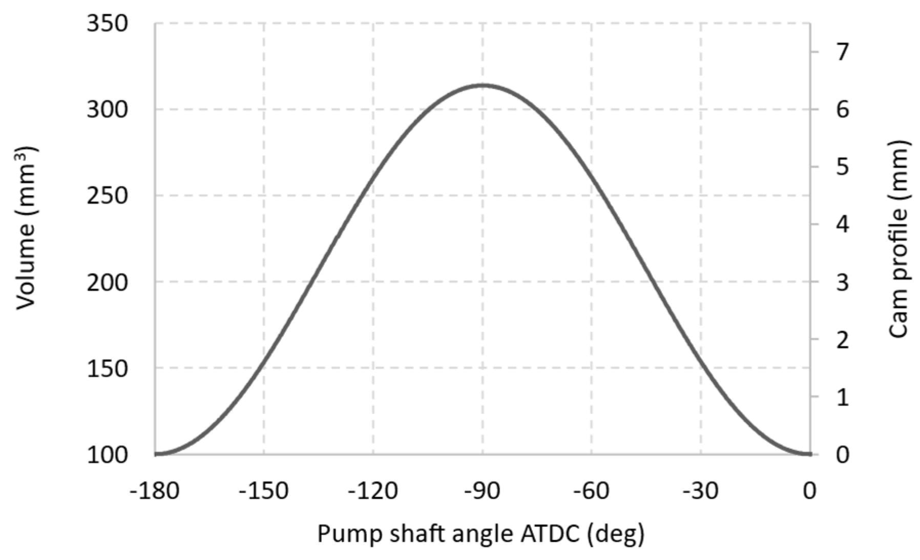
Figure 1. Volume of pump chamber and cam profile vs. pump shaft angle.
Energies 17 01656 g001
Figure 2. Schematic of experimental setup.
Energies 17 01656 g002
Figure 3. Bulk modulus of compressibility for diesel fossil fuel, biodiesel, and HVO versus pressure, according to [24].
Energies 17 01656 g003
Figure 4. Pump operating cycles—1500 RPM.
Energies 17 01656 g004
Figure 5. Pump operating cycles—3000 RPM.
Energies 17 01656 g005
Figure 6. Pump operating cycles—1500 RPM vs. 3000 RPM—high-pressure case (H).
Energies 17 01656 g006aEnergies 17 01656 g006b
Figure 7. Volumetric efficiency vs. pump shaft speed (for low (L), medium (M), and high (H) pressure) and volumetric efficiency vs. pressure (for 1500 and 3000 RPM).
Energies 17 01656 g007aEnergies 17 01656 g007b
Table 1. Injection pump specification.
Pump Specification
Pump modelRobert Bosch GmBH (D), model CP4.1
LayoutSingle plunger, 2 strokes per shaft revolution
Nominal max pressure1800 bar
Typical speed range750–4200 rpm
Nominal pump displacement427.4 mm3/rev
Nominal flow rate range38–215 dm3 per hour
Dead volume100 mm3
Piston diameter6.48 mm
Piston stroke6.48 mm
Table 2. Instrumentation specifications.
Flow Rate Measurement
DenominationSensorRange (L/min)Acquisition
VFM1VSE Volumentechnik, Neuenrade (D), model VSI 0.10.01–10National Instruments, Austin (TX, USA), model PXIe 6341
VFM2
Pressure Measurement
DenominationSensorRange (bar)Conditioning
PT1Kistler, Winterthur (CH), model 40670–3000Kistler, Winterthur (CH), model 4618
PT2Kistler, Winterthur (CH), model 40050–5Kistler, Winterthur (CH), model 4618
PT3AEP Transducers, Modena, (IT), model TP160–20National Instruments, Austin (TX, USA), model 4330 PXIe
PT4Kistler, Winterthur (CH), model 40670–2000Kistler, Winterthur (CH), model 4618
Injection pump drive system
ComponentDescription
Electric driveAsynchronous motor and frequency converter
EncoderQuadrature encoder1800 pp/rev
DAQ System
ComponentDescription and specification
DAQ chassisNational Instruments, Austin (TX, USA), model PXIe 1088
Strain/bridge moduleNational Instruments, Austin (TX, USA), model PXIe 4330, 8 channel, 24 bit, Strain/bridge input module
IO moduleNational Instruments, Austin (TX, USA), model PXIe 6341, multi-channel Analog–Digital Input, Counter-500 kS/s
Table 3. Tested fuel specifications.
Specifications at 40 °C
Fluid IDCommercial NameViscosityDensityRegulation Compliance
(mm2/s)(kg/m3)
Diesel“Diesel+” by ENI2.0820EN 590
WCO“WCO” by DP Lubrificanti4.1843EN 14214
HVO 1“MY Ren. Diesel” by NESTE3.0780EN 15490
HVO 2“HVOLUTION” by ENI3.1770EN 15490
Table 4. Test conditions—pump speed and rail pressure level.
Pump Speed
3000 RPM1500 RPM
Rail Pressure
Low Pressure (L)Medium Pressure (M)High Pressure (H)
750 bar1200 bar1500 bar
Disclaimer/Publisher’s Note: The statements, opinions and data contained in all publications are solely those of the individual author(s) and contributor(s) and not of MDPI and/or the editor(s). MDPI and/or the editor(s) disclaim responsibility for any injury to people or property resulting from any ideas, methods, instructions or products referred to in the content.