1. Introduction
The energy trilemma—energy security, energy accessibility and sustainability—has become a critical, global optimisation problem in the current geo-political and economic context. The authors propose a complex technical and financial model based on a logical structure designed in such a way that most energy end users can identify, quantify, and support the implementation of energy performance-improvement actions (EnPIA) and power quality indices improvement actions (PQIIA).
By implementing the advanced energy management system (AEMS) that is proposed in this paper, end users can obtain the capability to perform real-time identification of potential actions that can lead to increases in their overall energy performance, mitigate potential issues with power quality indices and, ultimately, evaluate the technical and financial potential to implement hybrid distributed-generation projects.
The capability for real-time analysis translates into an increase in the speed with which the end user can identify and implement various no-cost or low-cost measures, such as organizational actions, whilst medium-to-long-term analysis can lead to a better understanding of significant investment measures and actions that increase the overall values of energy performance indicators (EnPI), while also improving the quality of their technical and financial performance analyses.
As such, implementing the proposed AEMS can significantly contribute to decreasing the energy demand of the end user, thus increasing the overall profitability of their activity.
To identify the energy sectors with the highest potential to save energy via the implementation of AMES, the authors firstly undertook a thorough analysis of the principal energy efficiency legislation.
Increasing energy efficiency through investment in technology is essential to allowing energy-intensive businesses to compete internationally [
1]. However, rapid growth in energy efficiency in industry is more difficult, as the associated investment costs are significantly higher than those found in the tertiary energy sector.
The tertiary energy sector (residential, office, and commercial) has high and financially attractive potential to increase energy efficiency in buildings.
Romanian energy efficiency legislation states that every enterprise with an energy use higher than 1000 t.o.e./year must have an energy-management contract and must submit an annual energy performance-improvement plan (EPIP) to the relevant governmental body. The degree of implementation of the EPIP must be verified by a periodical energy-auditing procedure.
However, it was shown that, in Romania, EPIPs are not creating the desired efficiency. Some of the main identified issues include the lack of in-depth energy-monitoring capabilities, the impossibility of correlating various energy sources with the final product/service, inadequate communication between the energy manager and the relevant stakeholders in the company, top management not setting high enough targets for energy performance, the lack of state incentives for energy performance improvement, the lack of energy-efficiency-education programmes for employees, and the lack of interest in energy efficiency by companies for which energy costs are not relevant compared to other operational costs.
In order to encourage and support companies in achieving their energy performance targets and, implicitly, environmental sustainability goals, the International Organization for Standardization designed the ISO:50001 group of standards [
2], which guide end users in implementing certified energy-management systems (EMS).
Market research regarding EMS implementation in the European Union [
2] showed that there is currently no common approach to promoting the implementation of this standard in the EU. ISO:50001 certification is not mandatory (in some countries it is only recommended), and financial incentives are provided only for large energy users, thus limiting the implementation of SMEs in small and medium enterprises, the dissemination of good practices, and the development of a durable, qualified market for energy efficiency. Only well-informed companies will implement SMEs in order to create a competitive advantage over companies in the same field.
The global EMS market reached USD 24.73 billion in 2021 [
3] and is expected to grow from USD 27.31 billion in 2022 to more than USD 60 billion by the end of 2029, with a compound annual growth rate (CAGR) of 12%/year, as a result of the following six determining factors: the adoption of Industry 4.0 technologies in energy management, the digitization of power-grid infrastructure, the evolution of energy efficiency standards in emerging economies, the increase in governmental policies that are favourable for the use of sustainable energy, the increase in the implementation of smart grids, and the increase in global energy demand.
It is also expected that EMSs implemented at the industrial end-user level will make the largest contribution to the growth of this market due to the associated high investment, installation, and maintenance costs; the incorporation of Big Data and real-time analytics concepts [
4]; and the high degree of complexity of the industrial-sector energy boundary, compared to the tertiary-sector energy boundary.
The European Green Deal’s [
5] main objective is to achieve climate neutrality by 2050 by matching the amount of polluting emissions with the amount of emissions that are naturally absorbed, decoupling economic growth from resource use, stimulating resource efficiency through the transition to a circular economy, restoring biodiversity, and reducing pollution. As a direct result of the European Green Deal, there is increasing pressure on the entire energy sector, from production, transport, and distribution to the end user, to increase energy efficiency and thus reduce the environmental impact of day-to-day activities.
In addition, the fourth phase of the EU-ETS (European Union’s Emissions Trading System) mechanism for trading CO
2 equivalent allowances has led to significant increases in the EUA (European Union allowance) price, up to 98.01 EUR/certificate in August 2022 [
6]. As a result, the financial burden on conventional energy producers (fossil fuels) and users who own and operate combustion installations (thermal power stations, technological processes using fossil fuels, etc.) with installed thermal capacities of more than 20 MW
t [
7] has increased significantly.
The European Commission decided, at the end of 2019, to make energy efficiency a priority at the EU level with the
Energy Efficiency First! principle [
8]. In addition, in the second half of 2021, the package of legislative proposals entitled Fit for 55 was launched; in that package, the European Union proposed raising the targets regarding energy efficiency and the proportion of total energy use to consist of renewable energy sources as a means to act against climate change [
9].
The new target is to increase energy efficiency by at least 36–39% compared to the BAU (business as usual) scenario by 2030 by making energy savings (i.e., EPIP) mandatory in the period between the 1st of January 2021 and the 31st of December 2023, as well as by revising regulations on the monitoring and billing of thermal energy and increasing the energy efficiency of heating and cooling processes. In order to achieve these objectives, the European Union proposed that moderating energy demand should be the first target of the strategy [
10].
With this legislative package, the European Union also extended the applicability of the EU-ETS trading mechanism to the maritime sector and proposed the creation of a new CO2-trading scheme for the transport and buildings sectors by 2026, increasing the obligatory reduction in CO2 equivalent emissions from 40% to 61% by the end of 2030, with a reference value set for the year 2005. The free allowances for the aviation sector will also be phased out between 2023 and 2025.
The new approach of the European Union is that “the Polluter Pays!”, a concept defined in Directive 2004/35/EC, which was amended and updated on the 17th of June 2020: any company causing environmental damage is directly liable for it and is obliged to take all measures to repair or prevent it, bearing all related costs.
Therefore, the EU aims to take all required measures to reach environmental neutrality and serve as a positive example in the worldwide fight against climate change.
One way of achieving these targets is to increase energy performance (EnP) through the implementation of EPIAs by end users and to increase the use of electricity produced from renewable energy sources (RES) by implementing RES-generation projects on end users’ sites and/or contracting a 100% renewable electricity-supply service when the implementation of RES projects is not possible due to technological or on-site limitations.
Upstream, energy efficiency targets can be met by increasing energy performance in transmission and distribution grids, which can be achieved by replacing network elements with a high degree of physical and other wear and tear with new, energy-efficient equipment that is correctly sized in relation to the current maximum loads; these include both EPIAs implemented by electricity-transmission-system operators (TSO)/distribution system operators (DSOs), which flatten the load curve, and EPIAs implemented by end users and/or DSOs, which provide real-time optimization of the operation of a power-distribution grid (through correct phase balancing, power factor correction, and optimal reconfiguration).
Another means of reaching the targets set by the EU is to increase the energy performance of the end-user energy boundaries by quantifying and minimizing the impact of operating internal power-distribution grids in distorted electrical regimes—the total current harmonic distortion factor (THDI) in end-user-owned network elements can be minimized by implementing power quality improvement actions (PQIAs) by end users and/or DSOs (e.g., through demand-side-management (DSM) initiatives).
Although the main objective of the proposed AEMS is to increase the energy performance and profitability of the energy boundary where it is implemented, by achieving these objectives, the AEMS can generate a domino effect at the macroeconomic level by reducing the demand for electricity, part of which is currently produced from conventional sources, at the grid level. Reducing electricity demand at the end-user level also leads to reduced power and energy losses in upstream electrical networks (distribution and transmission). The AEMS can also be extended and implemented at the level of thermal-energy use; thus, the energy performance-assessment methodology proposed in this paper is useful.
The proposed AEMS has been designed to support the end user in the statistical and real-time assessment of evolution in energy performance, both at the energy-use level and at an overall energy-boundary level.
The development of the AEMS is based on the idea that the comprehensive monitoring of energy use is the cornerstone of any EPIP. The proposed AEMS has been implemented and tested by several types of end users, both in the tertiary sector (i.e., office buildings) and in the industrial sector (i.e., industrial production NACE codes), as will be presented in
Section 4.
Through its energy-demand forecasting and statistical analysis, the AEMS enables the quicker achievement of energy-efficiency targets and, thus, a faster transition towards environmental sustainability for the end users.
The proposed methodology was executed using the Py (Python) programming language and the Jupyter Notebook code builder. This approach allows for the utilisation of a language that is not specific to any particular platform (such as Py, C++, Java, etc.), ensuring compatibility with potential future software solutions and facilitating their integration into a unified, final solution.
2. State of the Art and Strengths/Weaknesses/Opportunities/Threats Analysis
In order to establish the main functionalities and capabilities of the AEMS, the authors conducted a state-of-the-art (SoTA) analysis regarding energy-management systems. The research was conducted both on experimental EMSs with a technology-readiness level (TRL) between one and six and on commercially available EMSs (TRL-9).
The most promising EMSs were analysed, and the results of the SWOT analysis are presented in
Table 1 and
Table 2.
There are six main state-of-the-art approaches that are currently applied to energy-management systems, [
18,
19]: classical methods, meta-heuristic approaches, stochastic approaches, model predictive control-based approaches, artificial intelligence methods and multi-agent systems-based methods.
The most frequently used type of framework for energy-management systems [
20] are centralized EMS, decentralized EMS, distributed EMS, and hierarchical EMS.
The SOTA and SWOT analyses identified several critical points that the AEMS needs to address in order to maximize the energy and financial performance of the energy boundary in which it will be implemented. Therefore, the AEMS opportunities lie in its ability to do the following:
Continuously monitor the PQIs at all relevant measuring points;
Measure and calculate the energy performance and therefore the financial consequences of the PQIs;
Measure and calculate EnPIs, rather than only monitoring the absolute energy flows, in order to establish benchmarking capabilities;
Normalize EnPIs by taking into account crucial variable factors;
Predict future changes in both the load curve and the corresponding EnPI in order to optimise the user’s performance in the energy market;
Analyse, suggest, and evaluate significant EPIAs and PQIAs from both a technical and a financial perspective;
Analyse, suggest, and evaluate the feasibility of renewable-energy projects and the integration of electricity-storage systems, considering both technical and financial aspects;
Develop reporting and notification systems tailored to the needs of different personnel within the organisation, such as technical, commercial, and top management staff.
The primary obstacles to the advancement of AEMS, as determined from the aforementioned analyses, are as follows:
The possibility of encountering challenges when integrating current monitoring systems with the AEMS (there is a low probability of this occurring, as the AEMS can utilise raw data from the monitoring systems, which can be transmitted to the server or cloud computing service where the AEMS is installed using any pre-established communication protocol);
The possibility of inaccurately identifying the critical variable factors for different energy uses. The impact can be reduced by configuring the normalisation system after the AEMS is installed, conducting a preliminary analysis of the measured data, and installing local variable-factor monitoring systems where feasible.
Integrating AEMS into current expert systems may pose challenges at the user’s energy boundary. However, these issues can be reduced by the AEMS operator inputting appropriate data during the installation/configuration of the system.
The main challenge faced by the various machine-learning-based energy-management systems that are currently in research and development is the proper configuration of appropriate data sets. Recent literature reviews point out that proper clustering and data-optimization tools could enhance efficient prediction by the ML model [
21].
The risks to be minimized after AEMS deployment are as follows:
Safeguarding the cybersecurity of the AEMS (this can be accomplished by implementing AEMS on site during the initial phase and utilising standardised communication protocols that are protected by distinct cryptographic keys);
Ensuring uninterrupted functioning of the AEMS, regardless of user status. This will be achieved by providing backup power sources such as UPSs and by developing a power-supply scheme that depends on the priority of energy uses;
Selecting an optimal sampling frequency that maximises performance while minimising the use of computing power and associated energy resources;
Ensuring proper data clustering and optimization prior to the learning-testing stage in the development of the AEMS.
Considering the advantages and disadvantages of the various EMS approaches and frameworks, the authors designed the proposed AEMS based on a distributed EMS framework, using the artificial intelligence (AI) approach.
The advantages of combining the aforementioned framework with the AI-based approach are as follows:
Framework:
The capability to process large and complex datasets;
The capability to ensure cybersecurity by having localized data storage;
The flexibility to manage diverse computing tasks;
The potential for scalability;
The ability to be both centrally and locally controlled;
A generally lower CAPEX than other types of framework;
Approach:
The ability to independently forecast the evolution of energy demand, energy performance indicators, energy baseline, environmental impact and the potential to improve overall energy efficiency;
The ability to regenerate the learning model based on updated datasets, thus enabling almost independent operation after deployment and proper learning/testing.
3. Proposed Methodology
The objective of the research was to conduct a comprehensive analysis of different technical solutions for enhancing EnPIs and their influence on PQIs. Additionally, the study examined the effects of increasing the share of distributed electricity resources (DER) on both types of indicators. The objective was to create a comprehensive, real-time model that would optimise the technical, energy, and financial efficiency of the energy boundaries on which it is applied.
Multiple autonomous analysis modules were developed to address different aspects, including assessing the potential for load-curve flattening (LCF), enhancing energy and economic efficiency by reducing the total current harmonic distortion factor (THD
I) and employing machine learning techniques to forecast energy use and, implicitly, the progression of EnPIs and PQIs. The incorporation of the analytical modules into the AEMS commenced based on the logical diagram of the AEMS (refer to
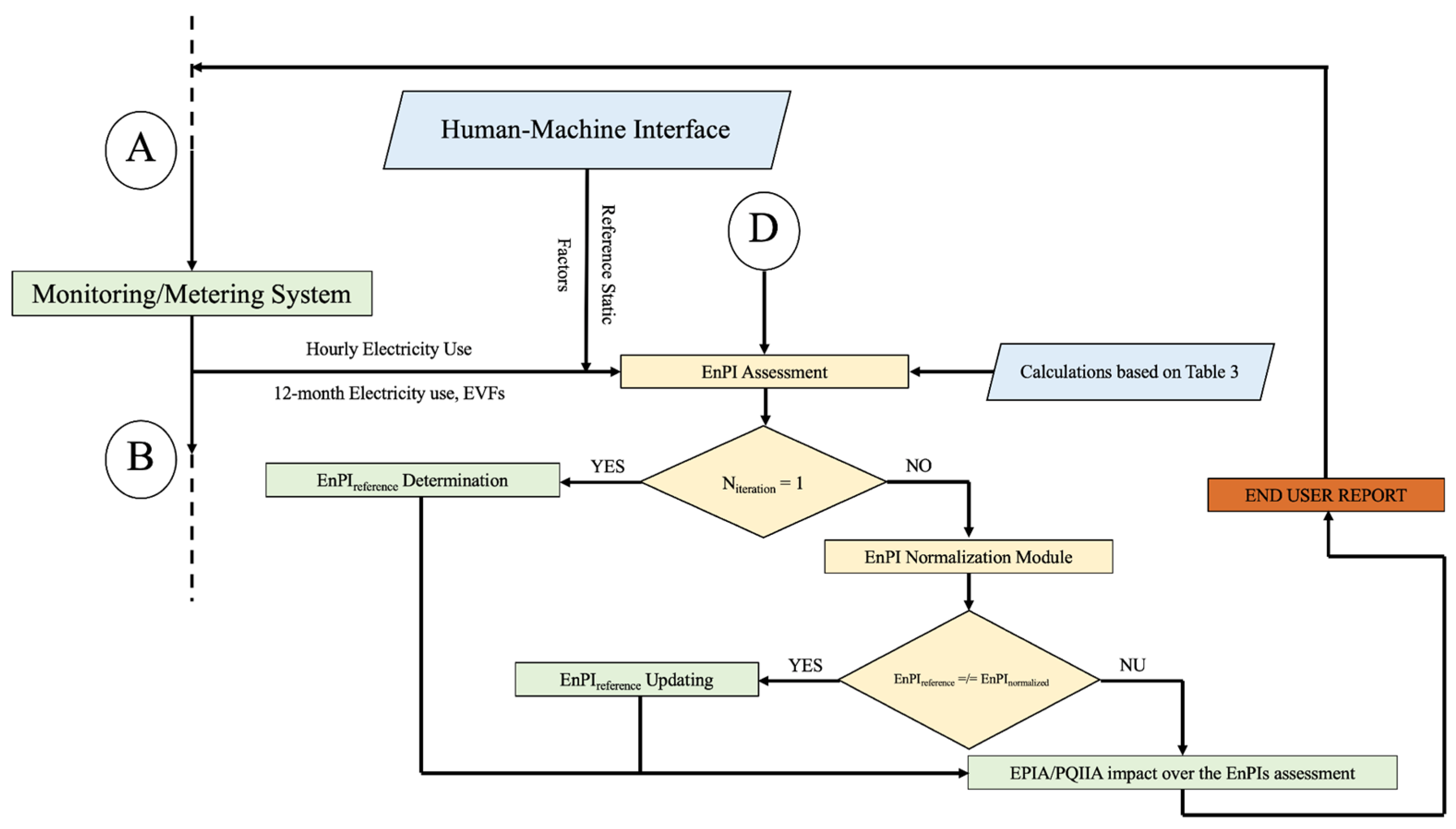
Figure 1).
The AEMS algorithm relies on a set of inputs, referred to as “Performance Criteria Established by the Organisation”. The key inputs include the duration of technical, energy, and economic analysis, as well as top managements’ hierarchy of priority targets, such as production, specific energy use, equivalent CO2 emissions, power quality, operating costs, and maintenance costs.
Once the first input data are established, taking into account the perspective and objectives of the company’s top management, the measurement and verification (M&V) protocol is designed and defined such that it functions within a logical loop. The deployed metering/measuring devices have a predefined measurement interval of one second and an aggregate period of fifteen minutes, as specified by the IPMVP (International Performance Measurement and Verification Protocol) [
22] and by the methodology for calculating the maximum apparent duration power (MADP)—S
M.
During the initial setup of the algorithm, the user needs to define/specify the economic indicators (ECIs). These indicators can be obtained from an ERP (enterprise resource planning) tool, accounting management software, or entered manually. The key indicators include monthly/annual energy costs, procurement costs of different production equipment or electrical energy end uses, monthly/annual operating costs, and monthly/annual maintenance costs (refer to label A in
Figure 1).
The user must also define and input the technical indicators (TIs), the technical characteristics of the equipment under monitoring/metering, which can be automatically imported from the ERP or manually introduced by the system operator (TIs can include the following: the rated power of the energy end use, the average daily load of the energy end use, the daily duration of use for the energy end use, etc.).
As the AEMS aims at digitizing energy-services procedures (such as energy management and energy auditing), the forecasting and normalization functionalities are essential. The authors developed, implemented, tested, and optimized a multi-layered machine learning algorithm that will be used to forecast multiple outputs of the system, such as the energy demand, the normalized expected EnPIs, the opportunity costs, and the potential for implementing LCF projects (and, implicitly, DR/DSM projects).
3.1. Measurement and Monitoring
After the monitoring loop begins (refer to label B in
Figure 1), the algorithm will collect the values recorded by all metering/monitoring systems during the “Monitoring” step, following the principle of simultaneity. The user can choose the EnPI evaluation technique to determine or establish the EnPI limit values. In order to encompass all potential situations, the user will have the option to select from the following choices:
- ➢
Determining the limit value of EnPI as the average value (EnPIlim = EnPIaverage) for a selected reporting period;
- ➢
Establishing the limit value of EnPI as an absolute value (EnPIlim = value); this method can be used if the necessary information is available. It is suitable when there are several energy boundaries that are similar and their maximum EnPIs are known and recorded at the corporate level;
- ➢
Determining the reporting threshold of EnPI, using a specific algorithm outlined in the current regulations and approved by the recipient.
The calculated values are subsequently compared to the reference values, which consist of EnPIs selected by the user in the previous stage and predefined PQIs, in accordance with the current legislation, regulations, and technical standards. A “Report” is generated if the values are within the specified admissibility limits, and the logic loop continues with the next batch of measured values (refer to label D in
Figure 1).
If the EnPI values do not meet the predetermined acceptable limits, the EnPI is normalised based on external variable factors (EVFs) or static factors (SFs). If the normalised Energy Performance Indicator (EnPI) is still higher than the specified limit value of the reference EnPI, a verification of conformity with the PQI will be conducted. The assessment evaluates the impact on the analysed EnPIs when one or more PQIs exceed the defined admissible limitations.
Every PQI that has recorded values outside the acceptable limits is quantified, and a partial report is generated. The report provides a quantitative analysis of the economic consequences of not meeting the specified cut-off value by the PQI and of how it affects the EnPI values. Subsequently, all of these partial reports are integrated into a comprehensive “Final Report,” culminating in a set of “Recommendations” specifically tailored for the user.
If the PQI values are within the set limitations and the current values (EFact), when compared to the values recorded in the previous reporting period (EFprevious), do not show a significant percentage difference for each of the assessed components, then the reason for non-compliance is organisational. A weekly report is prepared to quantify and accumulate economic losses and is then sent to the relevant decision makers.
Based on the findings of the SWOT analysis conducted in
Section 2, and considering the relevant legislative constraints, the initial phase of the research and experimental development of the AEMS involved selecting the appropriate energy boundaries.
Once the measured data are obtained from the existing monitoring and metering systems, they are transmitted to the server at a frequency of one data packet per second. These data are then utilised in a logical block to assess the accuracy of the recorded values.
The correctness of the datasets is of the utmost importance, considering the fact that one of the strengths of the proposed methodology consists of forecasting energy demand based on the forecasted evolution of the external variable factors.
The measured values are aggregated into subsets of either 900 (15 min) or 3600 (1 h) values, depending on the type of data being measured. Statistical analysis is applied to each subset of the records to eliminate any potential measurement errors. The proposed aggregation periods are corelated with the electricity market, thus ensuring optimal integration with other energy-market-specific software tools. The end user can add more aggregation periods if they are relevant for each analysed energy sub-boundary.
The mean value of each measured datapoint for each phase is determined. Equations (1)–(3) present an example for voltage-value verification, as follows:
where
represents the measured phase f voltage and
represents the number of measured values.
Then, the mean standard deviation is determined as follows (2):
where
denotes the mean standard deviation and
denotes the measured data variance.
The minimum and maximum measured values are also determined. Finally, the 25th, 50th, 75th, and 95th percentiles are determined using Equation (3), as follows:
where
denotes the analysed percentile rank.
When measurement errors, typically caused by communication or data-conversion errors, are recorded, the regression method suggested by [
23] is automatically utilised to enable the usage of the recorded data to train the neural network, which will serve as the foundation for predicting energy demand. This approach involves substituting the incorrect/corrupted data with the indicator value generated by computing the 95th percentile.
It has been shown that the most effective way to combine the recorded data is by using a one-hour interval. This approach ensures that the correlation with the changes in the EVFs is maintained. When aggregation periods of less than one hour are used, the variation in the variable factors is too small to adequately train the machine learning algorithm with a high level of confidence. When the aggregation periods exceed one hour, the variation of the EVFs increases significantly, which negatively impacts the accuracy of the energy end-use forecast.
To maximise the efficiency of storage-space use, the monitoring and verification logic block selectively retains statistical data that are important to the end user, such as the outcomes of technical, energy, and financial studies, for a period longer than one year. Energy data that can be measured and expressed in monetary units, like as electricity usage, are retained indefinitely. The data are stored this way because the data are modest in size and are recorded frequently, (15 min monitoring frequency in the PCC), which translates to a low memory requirement.
This data aggregation and clustering ensures the best ratio between data quality and data metering, processing and storage costs, thus offering an alternative method to the one suggested by [
24,
25].
Any variation from the allowed range, which is defined as VC ± 10%, for all voltage values, will be recorded in the log. Here, VC represents the contracted supply voltage that has been stated in the energy-supply contract. Typically, the rated voltage (Vr) of the network is used, although it can be adjusted based on an agreement between the DSO and the end user. In the given case studies, the contracted value (VC) and the rated value (Vr) are both equal to 400 V (three-phase power supply).
Following the installation of the monitoring system in multiple energy boundaries and the use of various three-phase class A quality analysers to showcase the interconnection and integrability of the AEMS, the second phase, which consisted of the development, deployment, and testing of the analysis modules, was implemented.
3.2. Power Quality Indices Assessment
To develop the algorithm for evaluating the PQIs (refer to label C in
Figure 1), electrical measurements were conducted using class A three-phase power quality analysers, following the IEC 61000-4-30 standard [
26]. These measurements provided a data flow of one package of measurements per second for a duration of 12 months. The measurements were taken at six specific low-voltage (LV) measurement points:
Industrial end user—one measurement point—two types of energy boundaries were assessed:
- 1.
Large energy boundary: The point of common coupling (PCC), located on the secondary winding of one of the existing 20/0.4 kV power transformers, which supplies approximatively 25% of the energy demand to the end user, was measured;
- 2.
Small-to-medium energy boundary: The power supply of an automated production line, in which highly effective current-waveform-disturbing devices were identified, was measured.
Tertiary sector end user 1 (in an office building)—one measurement point—two types of energy boundaries were assessed:
- 1.
Large energy boundary: The PCC, located on the secondary winding of the existing 20/0.4 kV power transformer, which ensures the power supply to the entire building, was measured;
- 2.
Significant energy use: The 0.4 kV power-supply circuit of the HVAC (heating, ventilation and air conditioning) system was measured.
Tertiary sector end user 2 (in four office buildings)—four measurement points—two types of energy boundary for each building:
- 1.
Large energy boundary: The PCC, located on the secondary winding of the existing 20/0.4 kV power transformer, which ensures the power supply of the entire building, was measured;
- 2.
Significant energy use: The 0.4 kV power-supply circuit of the HVAC system was measured.
The analysed PQIs are briefly presented in
Table 3.
3.3. Energy Performance Indicators Assessment
The EnPI evaluation algorithm was systematically built by incorporating calculation methodologies for each EnPI in a layered way. This approach allows the user to select the appropriate EnPI based on the specific details of their activity and thus maximises the modularity of the AEMS and ensures its capacity to be replicated in any other energy boundary. The EnPIs that have been suggested are concisely outlined in
Table 4.
The EnPIs were normalized with respect to five relevant variables (historical values), namely, mean outdoor temperature, relative humidity, cloud cover, lighting, and wind velocity.
Figure 2 displays the suggested logic design of the IPE analysis module. (
EnPI Analysis Module represented in
Figure 1).
The AEMS calculates the EnPI for specific time periods (week/month/year) and also allows for normalisation by comparing it to the changes in the relevant variables. The user benefits greatly from the AEMS results, as they can utilise them for reporting purposes at both the company level (establishing internal goals for energy performance and environmental impact) and at the level of national energy-regulatory agencies (submitting annual reports on energy performance and the energy questionnaires from the energy manager (EM) of the user).
The EnPI normalisation approach utilised Lagrange interpolation (4), which was found to offer a function comparable to Neville’s algorithm (7), but with a considerably reduced computation time (over 90% faster) at the expense of a slight decrease in accuracy (over 3.80%).
where
Explicitly, Equation (4) can be written as follows:
Multiple linear regression (8) results in a substantial MSE (mean square error)—higher than that from the Lagrange interpolation and Neville’s algorithm, with an average value over 5%, as a result of the inclusion of numerous dependant variables. Consequently, it is not advisable to utilise this method for EnPI normalisation.
The results of testing the analysed interpolation/normalization algorithms are presented in
Table 5. A dataset consisting of 210,240 datapoints (energy-use data and EVFs values collected every fifteen minutes over the course of one year) was used to compare the computation time and the computational burden of each analysed normalisation method.
The clustering, processing and normalization of real-time, high-sampling-frequency data by cloud-computing-based software solutions confirmed the conclusions of [
27] regarding the improved overall performance of the smart energy-metering system. This approach leads to an increased efficiency of the proposed AEMS with regard to input-data quality.
3.4. Energy Demand Forecast
To examine the link between EVFs and EnPIs and to forecast changes in EnPIs based on the EnPIn = f (EVFs) function, a complex machine learning framework was created by using LSTM (long short-term memory) and recurrent neural networks (RNN).
The RNN-LSTM was originally created to predict active power demand using only one external variable, the average external temperature. The LSTM-RNN parameterization was built through a series of iterations with the goal of identifying the optimal values of the hyperparameters that would result in the most accurate forecast of active power demand. The optimal hyperparameters are as follows:
- ➢
The length of learning sequence: 24;
- ➢
The number of neurons per cell: 192;
- ➢
The number of epochs: 20;
- ➢
The number of examples from a learning step: 24;
- ➢
The training/learning weight: 0.15.
After the hyperparameters that resulted in the highest level of accuracy for the LSTM-RNN were identified, the LSTM model was expanded to account for five variables: average outside temperature, insolation level, degree of cloudiness, relative humidity, and wind speed.
This development allows for the analysis of the correctness of the developed software model and the quality of the selected hyperparameters when new variable factors are included. In order to use this concept in a practical situation, the prediction of electricity consumption was based on meteorological forecasts. This approach allowed for the measurement and assessment of the uncertainties caused by inaccuracies in the meteorological predictions.
The open-source platform
https://openweathermap.org/ was utilised to forecast the EVFs. This forecasting was achieved by utilising a custom application programming interface (API) that offered an hourly forecast for a duration of two (2) days for each request. This API enables the transfer of up to 2000 queries per day, so a subscription can supply the daily weather data required for the 2000 distinct locations where the AEMS is in use. The returned results were further processed for incorporation into the database by converting them from the JSON format supplied by the API into a format that is compatible with the machine learning algorithm.
In order to incorporate five variable external elements into the machine learning algorithm, we utilised historical consumption data over a four-year period. This data was used to retrain the system’s learning model, while maintaining the same hyperparameters that were previously established. The forecasting of fluctuating external elements was conducted utilising the weather-data API.
Contrary to the findings in the initial phase of developing the LSTM-RNN, incorporating forecasted meteorological data led to greater uncertainty in predicting the absorbed active power. The uncertainty increased from an initial range of 0.5–2% to a range of 1–12%, depending on the accuracy of the meteorological data (real vs. forecasted).
When compared with state-of-the-art forecasting methodologies [
28], the proposed methodology leads to a 10% lower MSE on average.
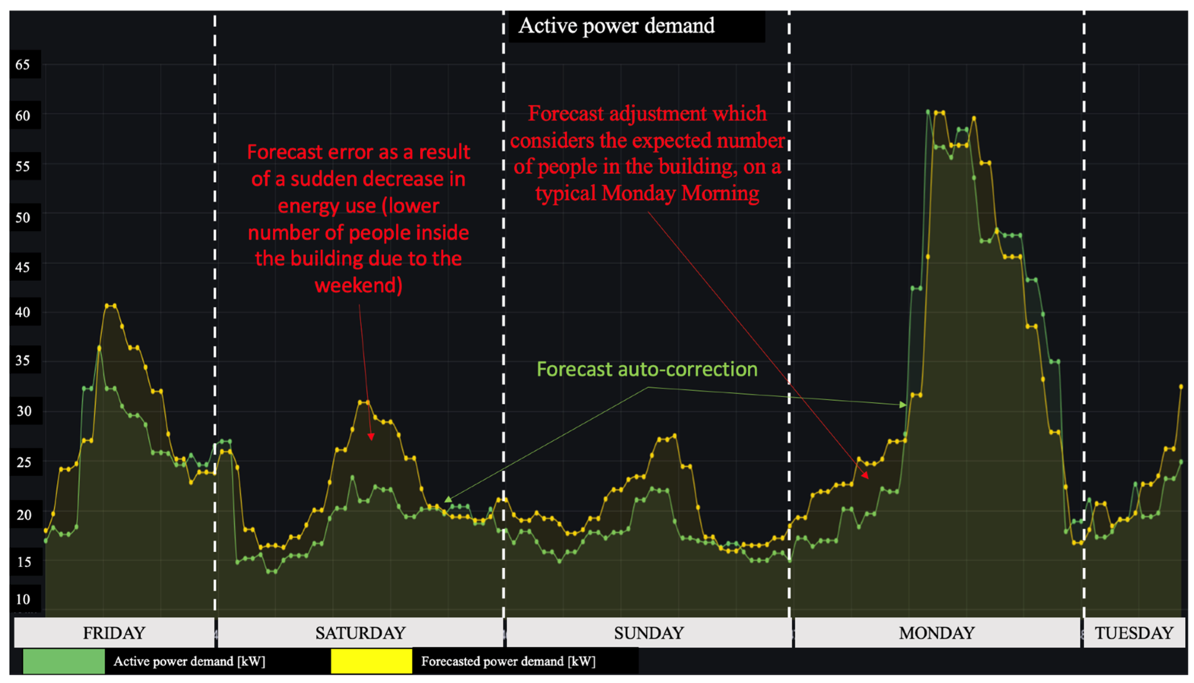
Given the particularities of the energy boundary being studied, which is an office building, the amount of electrical power consumed is directly influenced by the occupancy rate of the building. This relationship is seen in
Figure 3, where each point on the graph shows the total electric power demand aggregated over a one-hour period. The results are consistent across all data-aggregation categories.
The forecast of active power demand is conducted through a series of three separate and independent stages:
A forecast is generated for the upcoming hour, which is beneficial for participation in the balancing market (BM). For instance, at 15:00, the amounts of power predicted to be consumed in the next four (4) settlement periods, each lasting 15 min, are determined. The forecast is crucial for optimising the financial efficiency of participating in the balancing market, which offers a 15-min balance settlement available across the European Union.
A forecast is made for the upcoming hour: for example, at 15:00, the anticipated quantity of electricity to be consumed in the following 60 min, specifically until 16:00, is forecasted. This projection is crucial for calculating the energy efficiency of the energy subsystems associated with the examined energy boundary. The HVAC system (including chillers, air handling units, circulation pumps, and fan coils) is the driver of the most significant energy use (SEU) in the case study. Anticipating the electricity consumption for the upcoming hour allows for the assessment of the energy efficiency of the HVAC system beforehand by relying on past performance data.
A daily forecast is generated at 00:00 for the upcoming 24 h, predicting the amount of electricity that will be consumed in each 60-min interval. This projection is crucial both for participation in the day-ahead market (DAM) and for advance evaluation of the energy performance of the assessed energy boundary.
The machine learning algorithm yields the following advantages:
The ability to pre-assess the energy efficiency of the energy boundary being studied in order to identify any potential shortcomings in the operation or value settings for electricity end users;
The potential to enhance energy trading in the Day-Ahead Market (DAM).
For significant electricity end users, the capability to optimise financial efficiency in the balancing market by improving the accuracy of the consumption forecast.
Additionally, utilising forecasted energy-demand values, it is feasible to anticipate the progression of energy performance indicators within the monitored energy subsystem or even at the overall energy boundary.
The machine learning algorithm demonstrates excellent performance, with a 24-h forecast error of only 1.09%. This error is primarily caused by the variability between the forecasted and realised external factors, as well as by the absence of quantification for other relevant variable factors in the forecast, such as the hourly occupancy rate and tenants’ behaviour, specifically in terms of the temperature settings in the rooms. The variable factors examined in the case studies are significant and relevant to the assessed energy boundaries, with each of them producing a measurable effect on the power demand.
To enhance the precision of the forecast, it will be imperative to quantify additional variable factors, such as productivity. Additionally, a highly significant factor to consider is consumer behaviour.
To normalize the Energy Performance Indicator (EnPI), it is necessary to perform the following calculation subroutine:
- ➢
Check whether EnPIn = y is a function of EVFs = x by applying the vertical line mathematical method;
- ➢
If so, check whether y = f (x) is a one-to-one function by applying the horizontal line mathematical method;
- ➢
By applying the Lagrange interpolation, the expected values of y for any values of x can be determined;
- ➢
By implementing a ML system, the previously determined form of the function y = f (x) will be normalized based on the recorded data available from the measuring and monitoring system.
3.5. Power Quality Indices Improvement Action Potential Assessment Module
In accordance with the prevailing technical standards governing PQI analysis, the initial step always involves verifying the voltage total harmonic distortion factor. If the recorded values of the THDU fall within the specified limitations, the analysis can proceed to examine the recorded values of the THDI.
Operation of distribution networks in distorted current regimes results in elevated power and energy losses, as well as operational challenges. It is essential to keep the PQIs within the acceptable range in order to maximise the energy efficiency of electricity networks, regardless of whether they are used in residential [
29], commercial [
30], or industrial [
31] sectors.
The inefficient operation of power grids hampers the implementation od the previously outlined LCF methods. Operating the power grids under highly distorted waveforms can also result in the degradation of power transformers and electrical lines, further diminishing the overall energy efficiency of the power distribution system.
The power with which a transformer can be loaded for a specific regime without exceeding the maximum admissible temperature is determined by applying Equation (9), as follows:
where
[-] is the derating factor that considers the weight of the harmonic components of the current through the transformer windings and, implicitly, the losses generated by Foucault currents. The derating factor is determined using (10), as follows:
where
are the power losses generated by eddy currents in the transformers’ windings, which are divided by the rated Joule–Lenz losses occurring in the nominal operational regime, and K is a factor used to evaluate the influence of harmonic currents over the thermal stress on the transformer and is determined by applying relation (11), in which I
h is the effective value of the h rank current harmonics, as follows:
In order to evaluate the power losses generated by the current harmonics in power transformers, a hypothesis was created stating that the electrical resistance of the windings is constant at every current harmonic rank. The power losses are determined by applying Equation (12), as follows:
where
is the internal resistance of the power transformer primary winding, which is determined using (13), as follows:
where U
line,2 [kV] is the line voltage of the secondary winding of the transformer and k
j [-] is the transformation ratio.
As the electrical resistance of electrical lines cannot be considered constant, the power losses occurring in these elements can be determined by applying Equation (14), as follows:
where
is the electrical resistance corresponding to the h rank harmonic, which can be determined using (15):
The pellicular effect factor—kf—can be determined based on the radius of the conductor (r), the penetration depth δ, and the conductivity of the conductor .
The penetration depth can be determined by applying Equation (16), as follows:
To enhance the analysis module, an algorithm was created to assess the financial efficiency achieved by limiting the THDI value. This evaluation is based on the end user’s acceptable limit for the simple payback period.
Within this particular framework, the predetermined maximum value is set at 5 years, however it is possible to substitute this with any different value using the human-machine interface (HMI).
It is important to consider that the limit value of the SPP is dependent on the following factors:
The magnitude of the investment (tens of thousands, hundreds of thousands, or millions of EUR);
The company’s financial capacity, as measured by its turnover;
The nature of the investment, whether it involves technological, non-technological, or organisational processes;
The company’s available cash flow;
The company’s reputation and trustworthiness as evaluated by financial institutions, such as banks;
The existence and quality of business plans for each investment.
Therefore, based on the variables indicated above, the typical values for the SPP limit are 3, 5, and 10 years, respectively.
The financial-analysis module calculates the highest level of capital expenditures (CAPEX) that can result in the investment being fully recovered within a period of 5 years by minimising the harmonic ranks that are found to be significantly higher than the suggested limit of 5% of the fundamental value. Afterwards, the analysis module calculates the net present income that can be earned throughout the 10-year study period in compliance with the current legislation, thereby motivating the management to carry out the suggested investment.
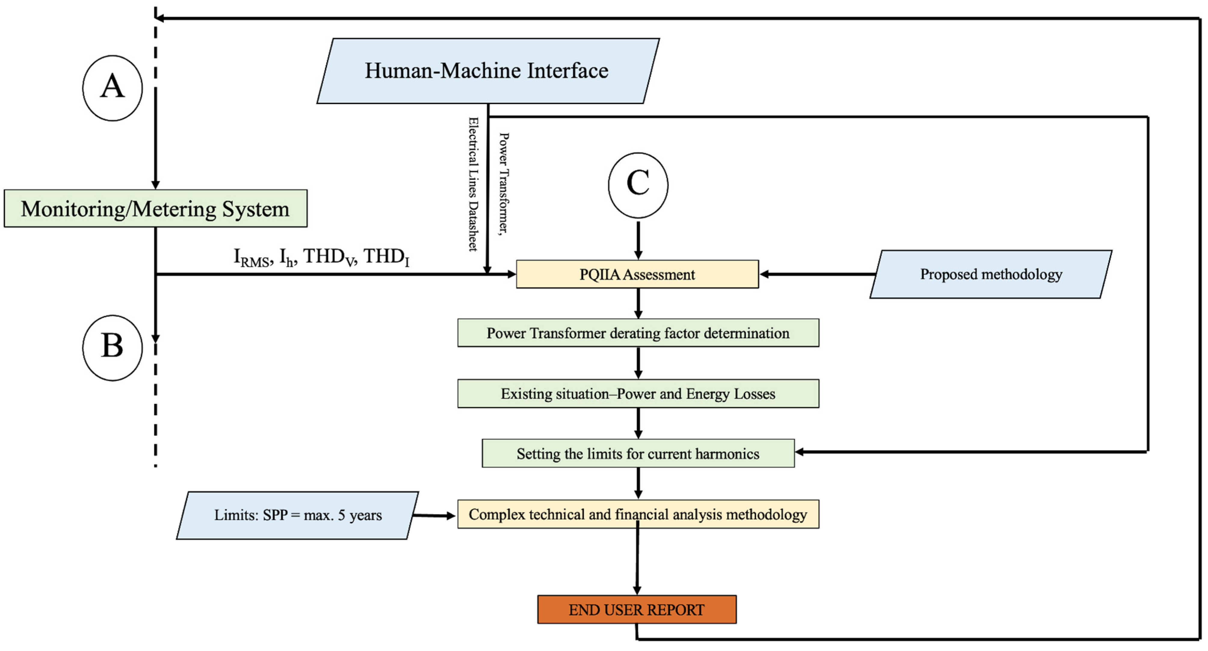
The logic block of the THD
I minimization potential analysis module is presented in
Figure 4.
The extension of the proposed LSTM-RNN to the PQIIA module leads to more accurate results (up to 40% more accurate) than are obtained from the VDM-LSTM analysis and that are on par with those obtained from the VDM-LSTM-1DCNN (variational mode decomposition long short-term memory one-dimension convolutional neural network) residual method [
32].
3.6. Techno-Economic Analysis Methodology
The proposed AEMS has a number of analysis modules (see
Figure 1), which generate techno-economic reports, as follows:
- ➢
The PQI/PQIIA analysis module, which ensures the real-time monitoring of the voltage sags, voltage spikes, voltage interrupts, load factor, peak factor, voltage and current imbalances, voltage and current harmonic distortions, and total power factor and quantifies the economic impact generated by low PQI values and the benefits that can be obtained by implementing PQIIAs;
- ➢
The EnPI analysis module, which determines and monitors the evolution of the selected EnPIs and, by aggregating the resulting values, normalizes them using a Lagrange interpolation technique, then forecasts the energy demand and the associated EnPI values using a LSTM machine learning algorithm.
Integration of the technical and financial components of each module is essential to establishing an overall financial function. This function will provide a comprehensive assessment of the financial profitability related to energy usage and the potential for improvement or maximisation.
This integration will also offer a comprehensive assessment of the possibility to mitigate environmental effects within the assessed energy boundary through the implementation of various activities recommended by the AEMS.
The analysis modules described in this chapter present the key financial outcomes produced by the AEMS in
Table 6. The AEMS results have been incorporated into the Human-Machine Interface, which was created using the Grafana open-access platform [
33]. This integration allows for the generation of comprehensive reports that provide an overview of potential energy savings, cost savings, and the potential reduction in environmental impact. The financial analysis equations are presented in
Table 7, and the variables are briefly presented in
Table 8.
The opportunity cost (OC) is the benefit an organisation loses when it makes a decision.
The decisions that OC quantifies consist of applying or not applying EnPIAs, PQIIAs, or DER projects. The OC plays a crucial role in determining the capital structure of an organisation, and, for this, it is important that the compared scenarios involve a similar level of risk.
In order to determine the values of the net present values (NPV) in the two scenarios (without and with the project), the techno-economic calculation methodology presented below will be followed. The input data of the actual scenario NPV and the optimized NPV are presented in
Table 9.
To determine the actual NPV, the investment cost (IC) will be considered null. The operation and maintenance cost (
) will be determined using Equation (17), as follows:
where
—is the yearly electricity cost in year t, in which
is the yearly electricity use and
is the adjusted electricity price in year t, and
is the yearly cost of natural gas in year t, in which
is the yearly natural gas use and
is the adjusted price of natural gas, in year t.
is the yearly operation and maintenance (O&M) costs, in which is the salary costs for the O&M personnel, is the expenditures generated by preventive and corrective maintenance, and is the expenditures generated by production loss due to preventive and corrective maintenance.
The yearly gross income will be calculated using Equation (18), as follows:
where GI
act is the actual income generated by the current activity of the company.
The yearly net income is thus determined by applying Equation (19), as follows:
where
is the yearly taxes applicable to the gross income.
The yearly net present value will be
where
—is the yearly discount factor.
The cumulated net present value is determined by applying Equation (21), as follows:
The discounted total costs are determined using Equation (22), as follows:
The internal rate of return is determined by applying Equation (23), as follows:
where
is the discount rate for which the NPV is equal to EUR 0.
To quantify the financial results of implementing the proposed EnPIAs/PQIIAs/DER projects, the input variables presented above are adjusted.
The investment cost is adjusted to the following:
The optimized (opt) operation and maintenance costs are evaluated using Equation (17), as follows:
The optimized gross yearly income is determined with the adjusted form of Equation (18), as follows:
where
is the energy-saving benefits generated by implementing the proposed measures and quantified by reducing the energy-associated costs, and
is the non-energy benefits generated by implementing the proposed measures and quantified by reducing the yearly operation and maintenance costs.
The yearly optimized net income is determined by adjusting Equation (19), as follows:
The yearly net present value becomes
The cumulated yearly net present value, the total discounted costs, and the internal rate of rentability are determined by adjusting Equations (21)–(23), as follows:
The OC analysis is conducted when the EnPI/PQI values exceed the limits established by the legislation or by the user. The analysis is repeated periodically, either monthly or yearly, depending on the type of energy meter. This process continues until the user implements the EnPIA/PQIIA/DER project, which is necessary to bring the indicator values within the set limits.
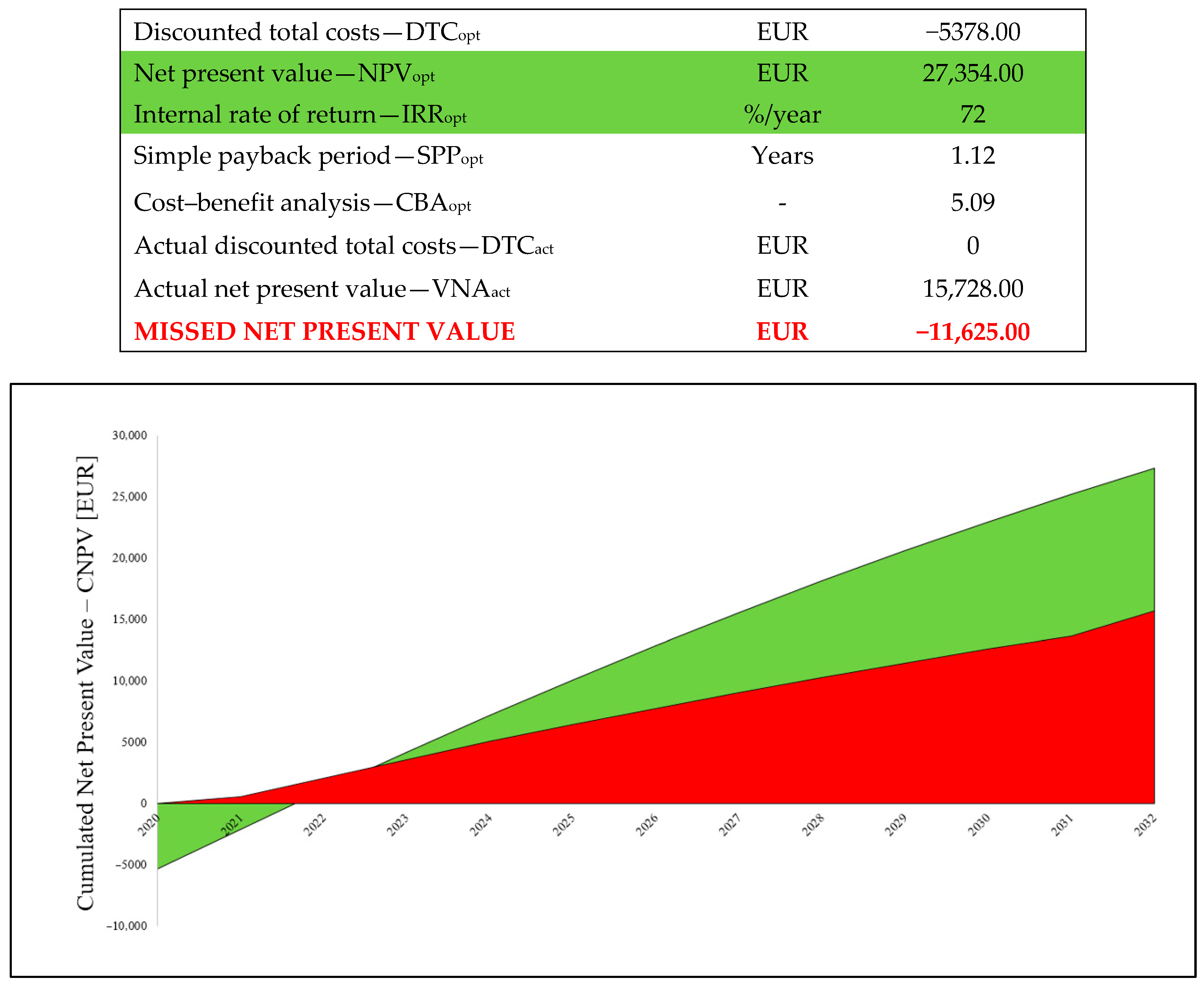
Each OC analysis is completed with a summary report presenting the results of the main indicators of the techno-economic analysis, IC, NPV, IRR, SPP, and CBA, in the two scenarios (current and optimized), and the comparative graphical representations of the evolution of the CNPV for the two scenarios, as shown in
Figure 5 below.
As proved above, the use of the OC analysis compared to the more conventional Cost-Benefit Analysis [
34] or the simpler cost=saving approach [
35] can lead to a significantly higher rate of project implementation, as it shows to the top management/decision-makers the loss of monetary gain caused by past lack of action, whilst also indicating the estimated gains that can be obtained if the project is implemented now.
4. Implementing, Testing, and Validating the Proposed Methodology
To test and validate the suggested methodology, the AEMS was deployed on six energy boundaries, as outlined below:
The AEMS monitoring system was installed on the PCC and on the secondary winding of a low-voltage substation in Sibiu County, Romania. This substation delivers approximately 25% of the power demand for an industrial platform in the automotive industry.
In Bucharest, Romania, the AEMS monitoring system was installed on the secondary winding of two power transformers that ensure the power supply for two different office buildings. Additionally, the AEMS monitoring system was installed on the power supply of the HVAC system of each building.
In Brașov County, Romania, the AEMS monitoring system was installed on the low-voltage side of an MV/LV power-distribution substation. A total of four circuits were monitored: the PCC, the secondary windings of a 20/0.4 kV power transformer, and the secondary windings of two 0.4/0.12 kV power transformers, which provide power to a milling production sector.
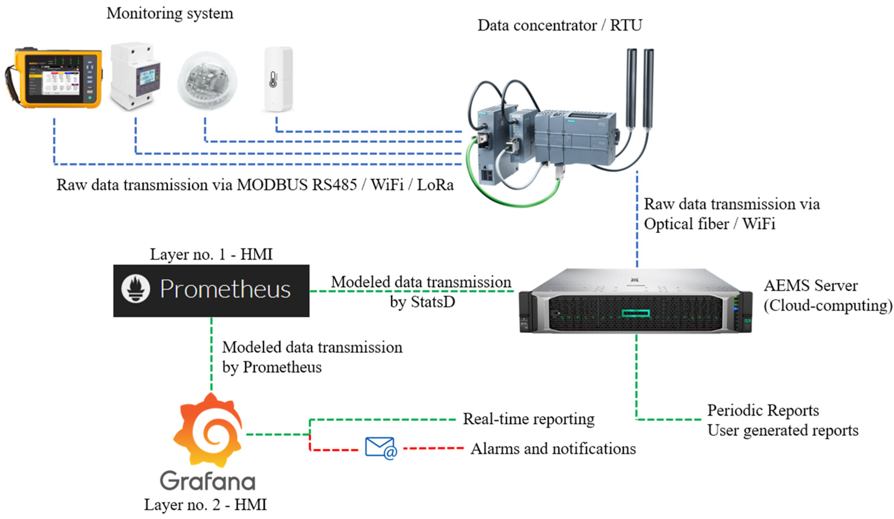
The overall architecture of the proposed AEMS is presented in
Figure 6. As can be seen, the raw data measured/monitored with class A power quality analysers/smart meters/variable factor sensors are transmitted via MODBUS, Wi-Fi, and LoRaWan to a data concentrator (RTU). From there, the aggregated raw data are delivered to the AEMS Server (cloud computing) via optical fibre and/or Wi-Fi.
After the various analysis modules are applied by the AEMS, the modelled data are transmitted via a StatsD daemon to the first layer of the human–machine interface (HMI), which was constructed using the Prometheus open source docker [
36]. Prometheus then feeds the second layer of the HMI, which was developed using Grafana’s open-source platform. This second layer of the HMI is the actual AEMS interface in which the end user can see all the results provided by the system and via which the real-time alarms, reports, and notifications are sent to the end user. The periodic reports and the user-generated reports are completed at the AEMS server level and are sent directly from the server to the end user as PDF files.
4.1. Power Quality Assessment Module Validation
In order to demonstrate the significance of reducing the THDI in a power distribution network owned by an end user, a case study was conducted on the energy boundary of an industrial end user (refer to item A in the aforementioned list).
The end user experienced a sequence of problems that occurred mostly in two production areas where multiple CNC (computer numerically controlled) machines were in operation. The CNC machines are outfitted with a three-axis DC electric drive system, consisting of 12 DC electric motors per machine.
The CNC machines have their power supplied by 0.4/0.12 kV transformers, which have a power rating of 112.5 kVA and are connected in the Yy6 configuration. These machines are specifically designed and manufactured in the United States. Over the past four years, the customer has replaced over 40 transformers of this particular type due to full failure, resulting in total additional expenses exceeding EUR 30,000.00 per year. Additionally, there have been financial losses of more than EUR 8500.00 each year due to temporary production stoppage.
The consequences of distorted operation are particularly pronounced due to the continuous operation of the examined end uses, which amounts to 8600 h per year, with the exception of occasional maintenance or repair periods, which average 160 h per year.
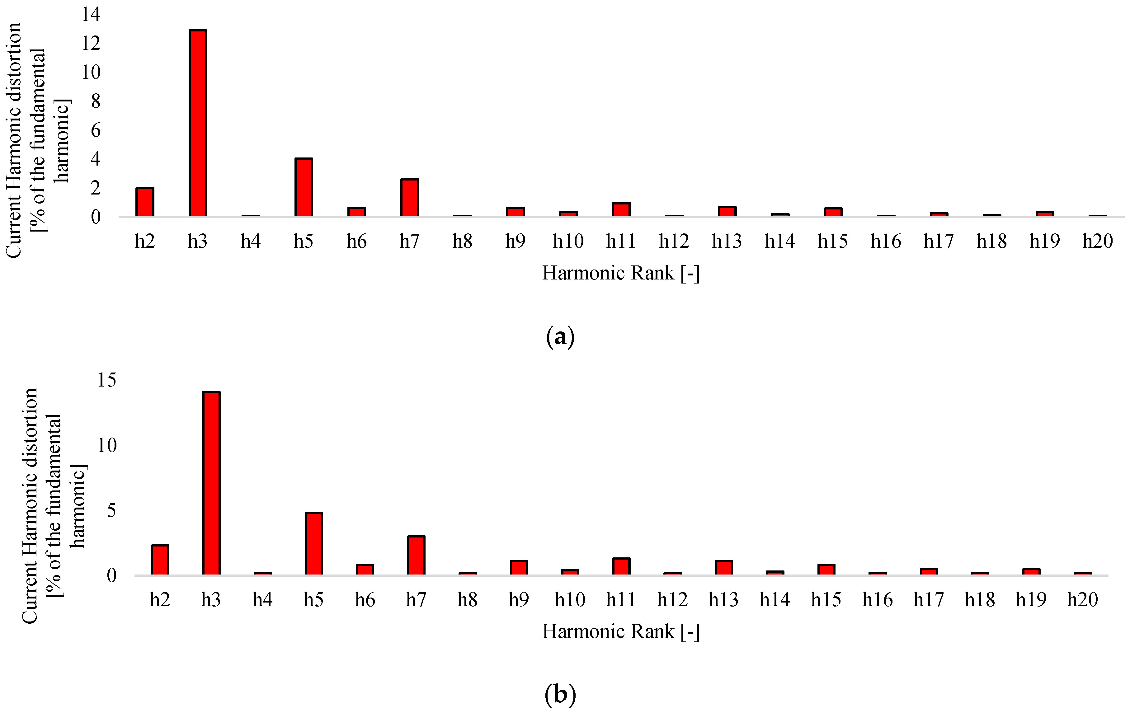
The analysis conducted during the experimental investigation revealed that two categories of CNC machines produced notable harmonic electrical-current disturbances, as depicted in
Figure 7. These disruptions were mostly caused by the power-conversion devices (rectifiers) used to supply power to the various DC motors.
Subsequently, a thermographic analysis was conducted on the power transformers feeding the CNC machines. This analysis revealed that both the 0.4/0.12 kV power transformers and the connected power lines were working under significant overload conditions.
The temperature of the power line connecting to the secondary winding of the power transformer was 139.6 °C, which exceeded the rated working temperature by more than 70% (65–70 °C).
By installing an active harmonic filter (AHF) system, the user successfully mitigated the rank 3 (which generates an influence on the neutral conductor), 5, 7, and 9’s current harmonics. This reduction in harmonics had a positive impact on the neutral conductor and prevented power-transformer failures. Consequently, the installation of the AHF system eliminated both additional power and energy losses in the distribution network, as well as non-energy-related financial losses such as equipment replacements and production downtime.
After a 72-h measurement campaign was conducted with a data-gathering rate of one dataset per second and using a class A three-phase network analyser, the database to test and validate the PQI/PQIIA analysis module was generated.
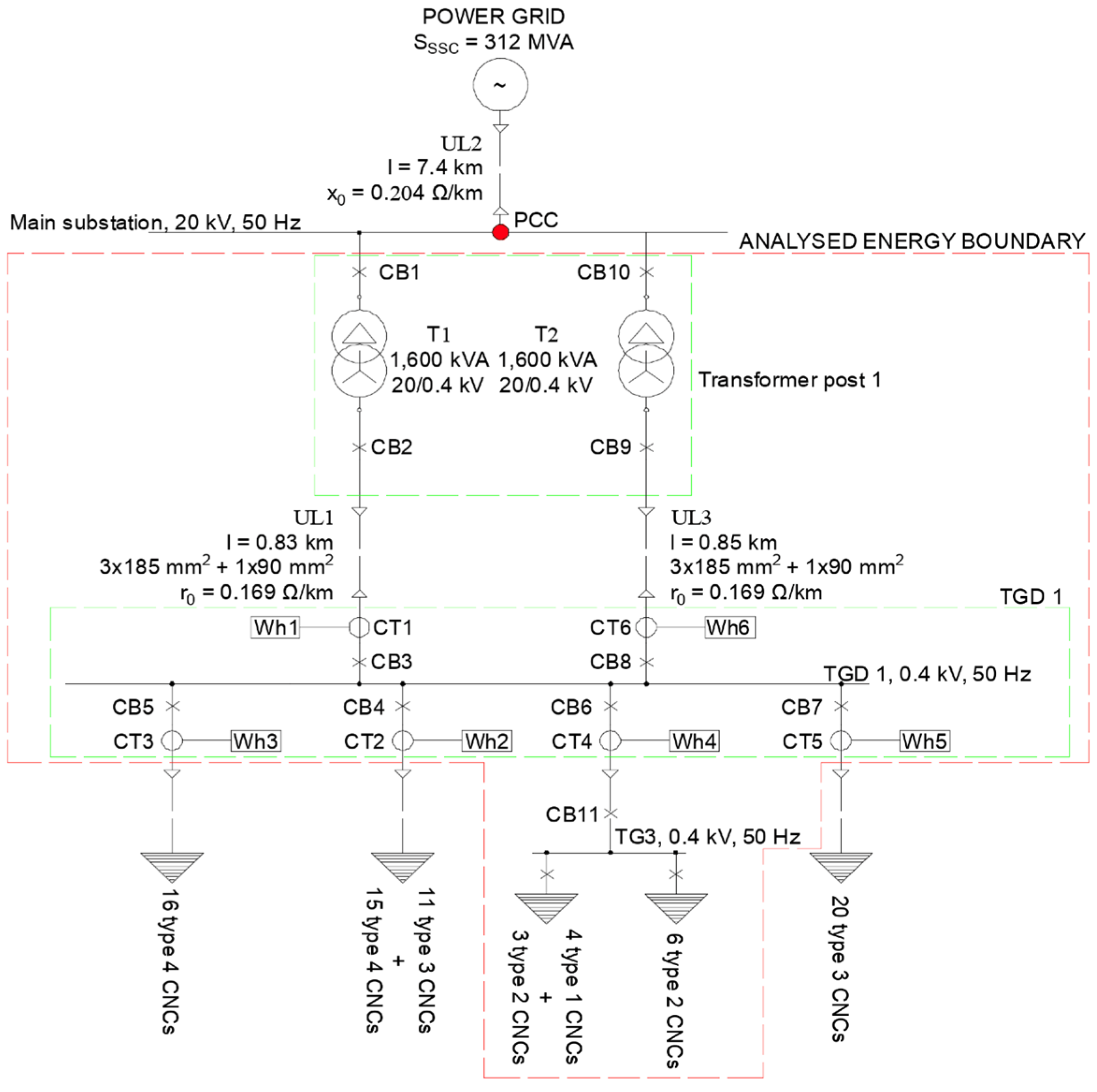
Considering the configuration of the examined substation, as depicted in
Figure 8, measurements were conducted on each output of the low-voltage distribution board to determine the specific origin of current harmonics.
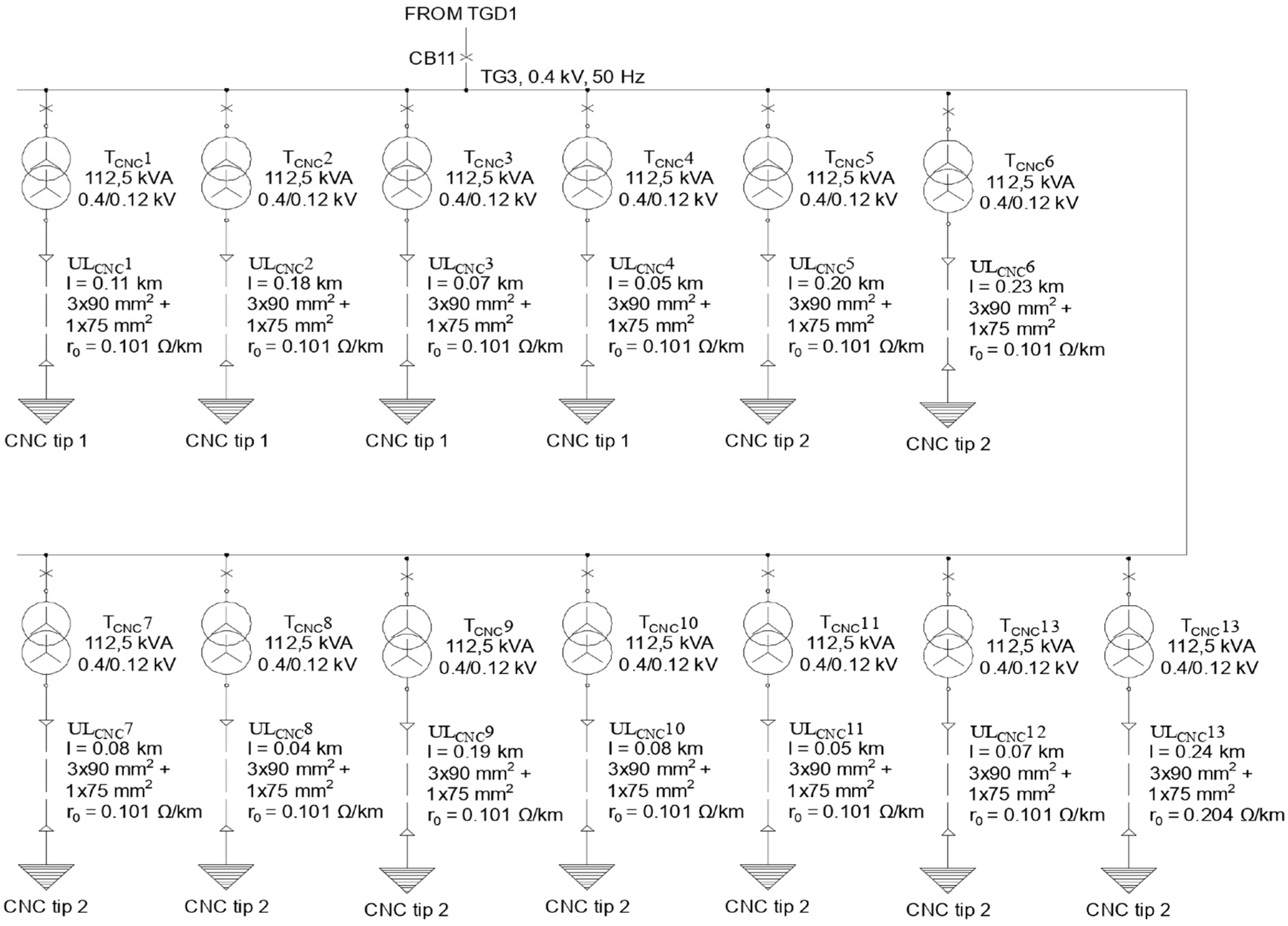
It was determined that the main source of electric current harmonics was TG 3 (General Distribution Panel no. 3) due to the grouping of CNC machines with the highest contributions to current harmonic distortion at this point in the network. The single-line diagram of TG3 is shown in
Figure 9.
Furthermore, a notable asymmetry in the electric currents was discovered, indicating a decreased emphasis on balancing the phase load. The case study also examined the influence of current harmonics on the energy efficiency of Underground Line no. 1—UL1. The rated values of the 0.4/0.12 kV power transformer and UL1 are presented in
Table 10.
By utilising the method outlined in
Section 3, the cost-benefit analysis demonstrates that the project has the potential to yield a net present value (NPV) of more than EUR 1.4 million over a 10-year study period. The total present cost (TOTEX) amounts to EUR 650,000. The payback period is 3 years, which is significantly shorter than the guaranteed lifetime of 10 years provided by the AHF manufacturer [
37]. Thus, it has been proven that this module may greatly enhance the energy and financial efficiency of end user distribution networks.
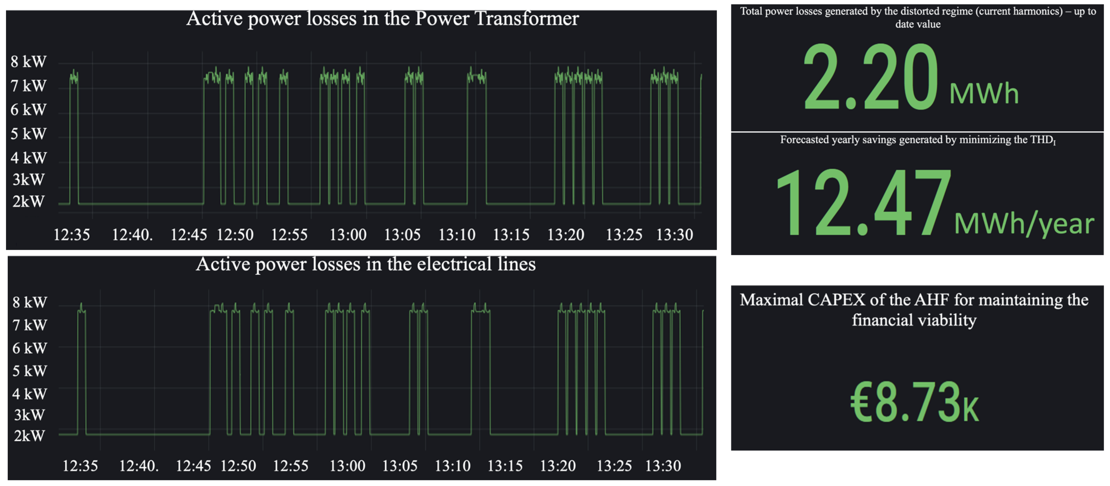
The same methodology was applied to the office buildings, with the results showing a maximal CAPEX value of 8730.00 EUR for the AHF in order to maintain financial viability, as shown in
Figure 10.
4.2. Power Demand Forecast Module Validation
The machine learning algorithm has been developed, deployed, tested, and extended on an energy boundary that pertains to an end user in the tertiary energy sector, namely, an office building. An analysis revealed that the HVAC system accounts for almost 70% of the total yearly electricity use, as it supplies heating, cooling, and domestic hot water by electrical means.
During the initial phase of developing the machine learning and prediction system, only the relationship between the active power input and the average outdoor temperature was taken into account. The parameterization was conducted through iterative processes, with the goal of discovering the ideal values of the hyperparameters that would result in the most accurate active-power-demand projection. After completing 20 epochs, which are sequential sweeps of the available data, the root mean square error was determined to be 15.96 kW, with an accuracy of less than 0.02%.
The generated genetic algorithm was further tested using a dataset provided by the Department of Energy (DOE) from an office building in Richland Township, Benton County, Washington State, USA. The presented data consist of the absorbed power and average outdoor temperature, aggregated on an hourly basis, for a period of three years (2018/2019/2020). The outcomes derived from implementing the machine learning algorithm are displayed in
Figure 11 and
Figure 12.
In order to incorporate five variable external elements into the ML algorithm, as described in
Section 3, historical consumption data spanning four calendar years were used to retrain/regenerate the system’s learning model. The hyperparameters that were previously identified were used in this process.
Figure 13 displays the outcomes of a monthly forecast period.
Testing has shown that the proposed methodology leads to an average daily forecast error of 1.1%.
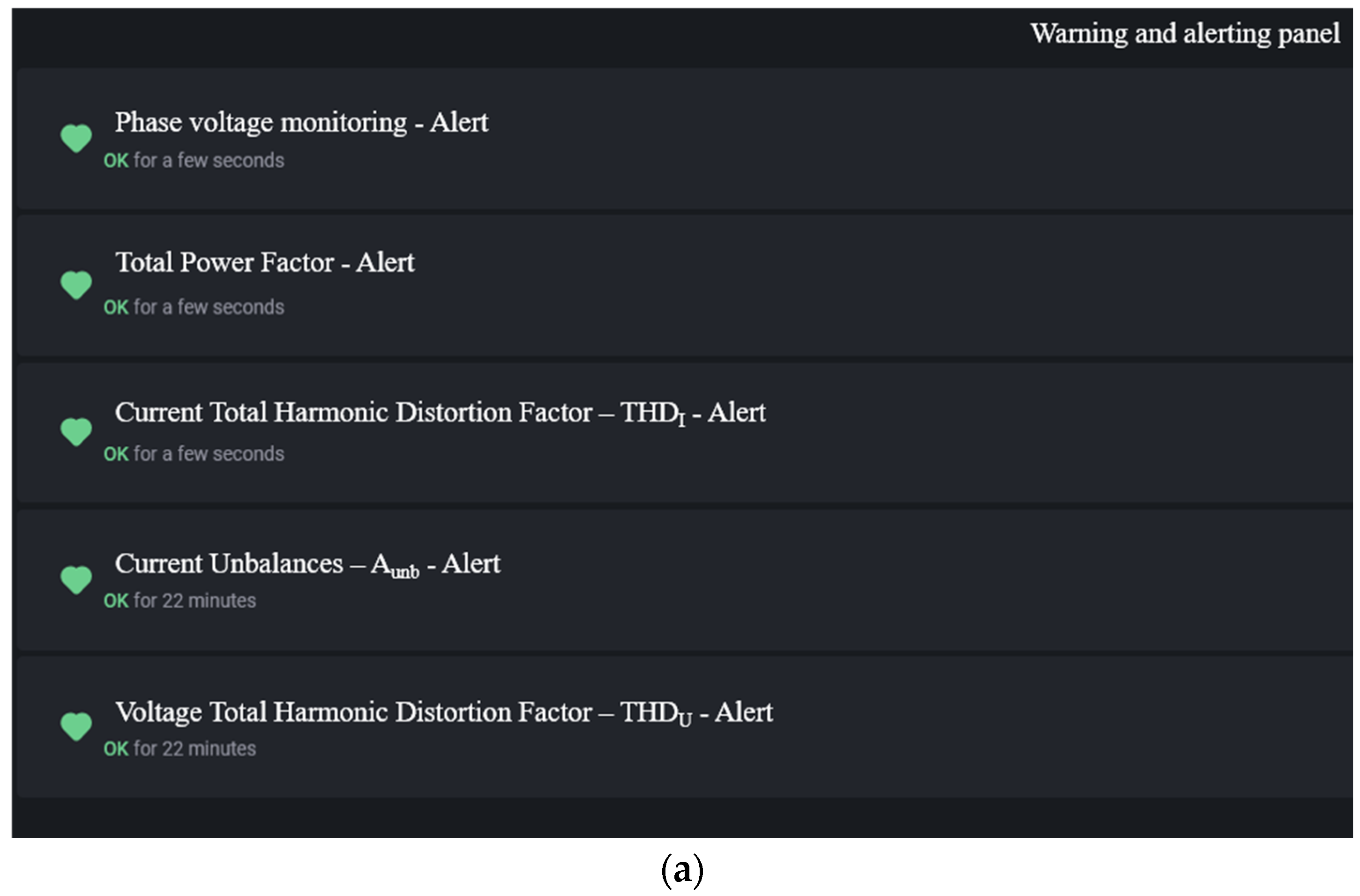
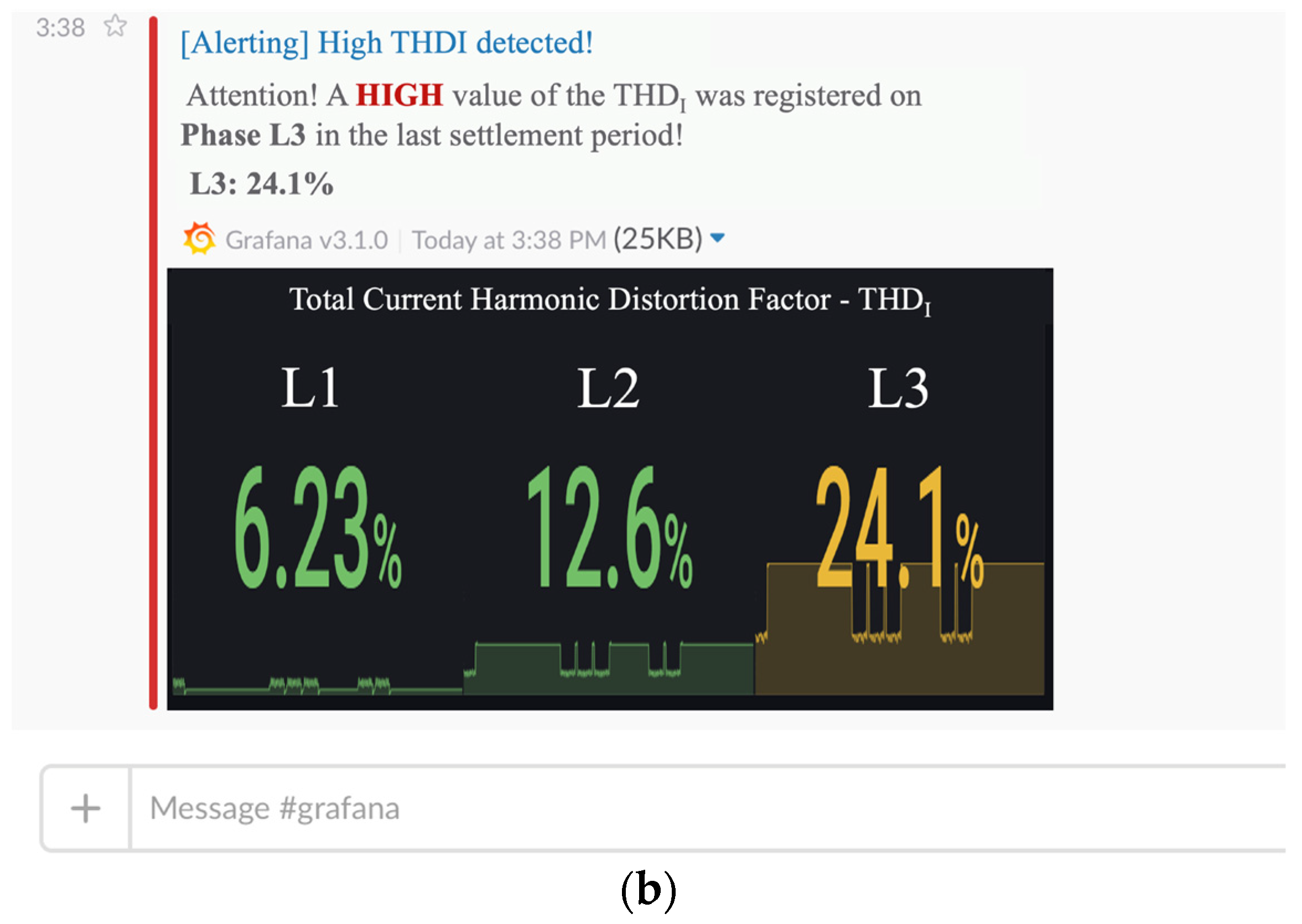
After the development, implementation, testing, and enhancement stages of the advanced energy management system proposed in this work were completed, the system’s alert and notification features (refer to
Figure 14) were successfully deployed and demonstrated.
By implementing the AEMS and running its analysis modules over a relevant period of time (more than 6 months) for the office buildings presented in the beginning of
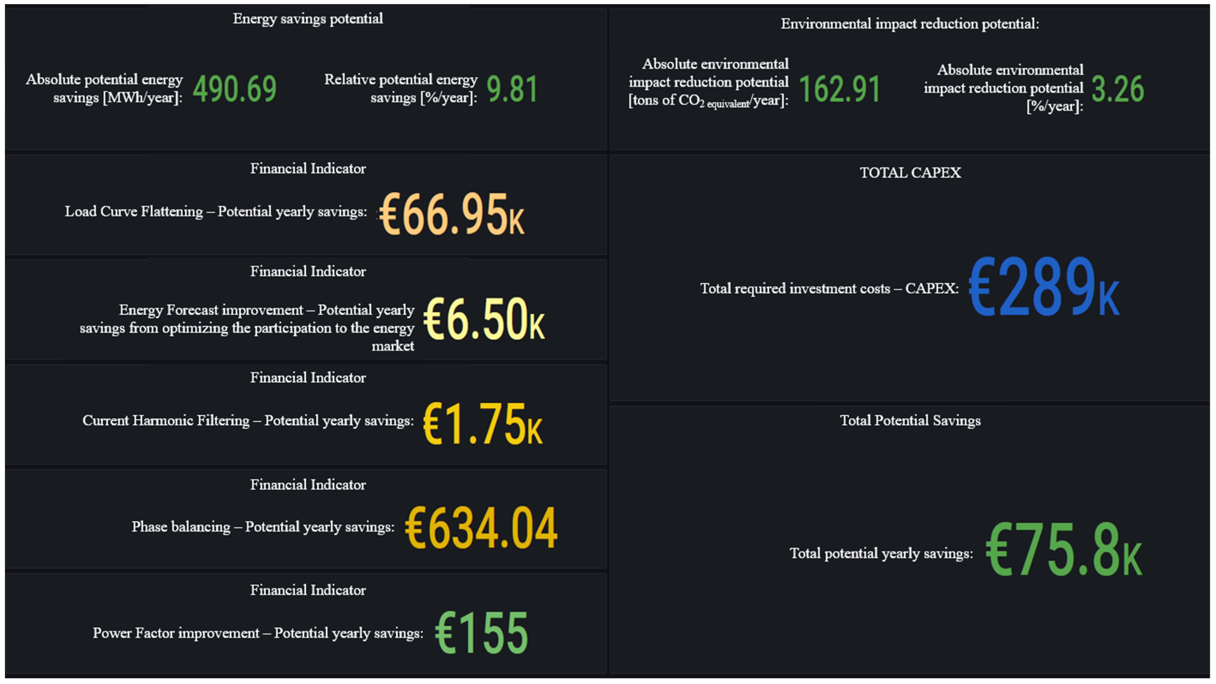
Section 4, it was proven that the proposed methodology led to the identification of various EnPIA/PQIIA, which, if implemented, could lead to energy savings of more than 490.69 MWh/year [9.81%/year] for the analysed energy boundary, with a potential environmental-impact reduction of approximatively 162.91 tons of CO
2 equivalent per year [3.26%/year], considering a conversion factor of 0.33 tons of CO
2 equivalent/MWh for electricity and 0.202 tons of CO
2 equivalent/MWh for natural gas.
As shown in
Figure 15, the total potential yearly financial savings amount to 75,800.00 EUR/year, with a total CAPEX of 289,000.00 EUR, leading to a simple payback period of less than 4 years (3.81 years).
The main EnPIA/PQIIA/LCF measures identified by the AEMS for this particular energy boundary were as follows:
The installation of an AHF to mitigate the high values of the THDI in the PCC—high values caused by numerous VSDs (Variable Speed Drives) and Rectifiers;
The implementation of a LCF project consisting in deploying a 150 kWp/100 kWAC PV powerplant coupled with a 50 kWh BESS;
The rebalancing of four different low-voltage distribution boards to ensure an optimal current imbalance (5–10%);
The reparameterization of the existing APFC (automatic power factor correction) system to better follow the variation in reactive power demand and ensure that the 0.9–0.99 power factor is as constant as possible.
Based on the experimental study and work conducted for this paper, numerous potential areas for future research have been identified. These areas are of relevance in terms of energy-efficiency goals and the ongoing battle against climate change.
While the AEMS has been built with modularity as a general goal, additional study is required to explore its potential applicability for small energy end users, such as SMEs (small- and medium-sized enterprises), given their substantial share of the total energy demand (13% of the global total energy demand [
38]).
It has been shown that the behaviour of energy users is an important factor that influences the quality of the results provided by the AEMS. One effective approach to influencing the behaviour of energy consumers and reducing the fluctuation in electricity consumption across elements of the distribution network is the implementation of a dynamic tariff mechanism (DTM) based on network zones. This mechanism incentivizes energy consumption during periods of low demand and imposes penalties for consumption during peak demand.
Whilst the proposed AEMS has the potential to increase the energy efficiency of the regional power grid if it is installed on significantly large end users in that region, a potential approach by which to further accelerate the improvement of the DSO’s energy performance is the implementation of a demand response (DR) system, organised by grid zone and user type. Such a system may be appealing for domestic purposes, but implementing it would require substantial investment by the DSO to replace electrical switchboards in homes. This replacement would enable the remote control of certain circuits, such as those operating the refrigerator, washing machine, air conditioning, and so on. To evaluate the technological, financial, and commercial feasibility of this activity, it may be necessary to conduct a thorough study on public acceptance of the idea and perform a cost-benefit analysis.
Moreover, the tertiary sector, which includes shopping malls and logistics warehouses, is highly suitable for the implementation of a demand response (DR) system because the end users in this sector possess high volumes of high-capacity refrigeration and cooling systems.
In the energy-services sector, machine learning and artificial-intelligence techniques can be applied to optimise monitoring systems like building-management systems (BMS) and warehouse-management systems (WMS) and to further accelerate the implementation rate of Energy Performance Contracts (EnPCs), by reducing the technical and financial risks taken by the stakeholders [
39].
5. Conclusions and Further Research
The paper has provided proof of the potential of the proposed AEMS methodology to greatly increase the implementation rate of projects for energy performance improvement, actions to improve power quality indices, and the installation of hybrid renewable energy sources-based systems by using an advanced machine-learning based forecast algorithm that quantifies all the aforementioned types of projects potential to generate revenue for the end user.
The AEMS can be a critical tool for transitioning towards environmental sustainability for multiple types of end users, as it has been proven to be applicable to both industrial and commercial end users, regardless of their size—as such, policy makers could mandate the obtaining of attractive, advantageous financing for energy-related projects so that the beneficiary has the obligation to also deploy such a system alongside the main scope of work. This approach can, in turn, lead to better and more accurate monitoring of the results obtained by main project throughout the monitoring period.
With an average MSE of 6%, the proposed Advanced Energy-Management System can also function as a monitoring and verification tool, which is essential for discovering and evaluating the chances to implement and monitor energy performance contracts—EnPCs. In this case, the Energy Service Companies can implement the AEMS for their potential clients, and the AEMS could represent the common ground between the two entities and the financial institution that is funding the project, thus reducing the technical and financial risks associated with the deployment of large-scale EnPCs.
The AEMS testing results suggest the need to evaluate the legal, commercial, and financial aspects of modifying the existing financing mechanism for RES-generation capacities. Some changes to the non-refundable financing mechanism should be done in order to incentivize end users who want to actively participate by implementing hybrid systems (distributed generation plus storage). By doing so, they will directly contribute to flattening the load curve at the level of the regional power-distribution grid.
The adoption of an advanced energy-management-system solution can further accelerate the ISO 50001 certification of end users, which can, in turn, lead to a domino effect in the supplier-client relationship between companies—an ISO 50001-certified company can commercially enforce the need for certification for all of its suppliers.

