Abstract
Accurately identifying a specific faulty monomer in a battery pack in the early stages of battery failure is essential to preventing safety accidents and minimizing property damage. While there are existing lithium-ion power battery fault diagnosis methods used in laboratory settings, their effectiveness in real-world vehicle conditions is limited. To address this, fault diagnosis methods for real-vehicle conditions should incorporate fault characteristic parameters based on external battery fault characterization, enabling the accurate identification of different fault types. However, these methods are constrained when confronted with complex fault types. To overcome these limitations, this paper proposes a battery fault diagnosis method that combines multidimensional fault features. By merging different fault feature parameters and mapping them to a high-dimensional space, the method utilizes a local outlier factor (LOF) algorithm to detect anomalous values, enabling fault diagnosis in complex working conditions. This method improves the detection time by an average of 22 min compared to the extended RMSE method and maintains strong robustness while correctly detecting faults compared to other conventional methods.
1. Introduction
Due to the frequent occurrence of accidents caused by lithium batteries, there is an urgent need to troubleshoot lithium-ion batteries. A lithium-ion power battery is a highly complex, nonlinear system in which internal state information cannot be directly observed, making it very difficult to diagnose faults. In fault development, even a small internal short circuit can lead to battery capacity degradation. In more serious cases, internal short circuits can lead to fire accidents [1]. Cell faults in battery modules can only be characterized by parameters such as voltage, current, and temperature. Therefore, fault diagnosis methods must rely on limited data to identify and accurately assess fault characteristics. Battery faults in battery modules can only be characterized by parameters such as voltage, current, and temperature. As a result, fault diagnosis methods must rely on limited data to identify and accurately assess different fault characteristics.
The methods commonly used for diagnosing power battery faults can be categorized into three broad categories: empirically based fault diagnosis [2], model-based fault diagnosis [3], and data-driven fault diagnosis [4]. The empirically based fault diagnosis method diagnoses battery faults by observing the characteristics of a battery system in different states. This method is effective for complex, nonlinear systems like lithium batteries as it does not rely on an accurate mathematical model. Although the working principle and diagnostic results of this method are easy to explain, it still necessitates extensive research on the battery’s failure mechanism and the characterization of prior knowledge when applied to battery fault diagnosis. The most widely used empirically based method in fault diagnosis is the threshold-based method. This method is advantageous due to its simplicity, ease of implementation, and wide application in the battery management systems of electric vehicles [5,6].
In certain cases, the single-threshold setting fails to differentiate between the normal state and the fault state of a battery. As a result, there are instances in which detection does not occur, leading to false alarms. This, in turn, adversely impacts the level of trust the battery management system commands from its owner. The empirical fault diagnosis method relies on the rational use of experience. As an auxiliary means of fault diagnosis, it can help extract the characteristic parameters of specific faults and improve the accuracy of fault diagnosis. However, when used as the main diagnosis method, it still faces several difficulties.
The model-based battery fault diagnosis method uses the difference between a model’s output and actual battery measurement data, known as the residual, to determine a fault [7,8]. Model-based methods can be classified into four categories: parameter estimation, state estimation, parity space methods, and structural analysis methods [9]. State estimation methods primarily employ observers or filters to reconstruct or estimate the internal state of a system, including variables like the state of charge (SOC) and the internal temperature of a battery. The residual, which contains fault information, is derived by comparing the estimated signal with the value measured by the sensor [10]. The main idea of the parameter-estimation-based fault diagnosis method is that faults affect the physical system and further lead to changes in the model parameters [11,12]. Therefore, detecting changes in the electrical and thermal model parameters of a battery can enable the identification and isolation of faults. The parity space method can determine the nonlinear relationship between a battery’s excitation signal and its response by analyzing the input and output values of the battery system [13,14]. The structural analysis method is employed to uncover and make use of the overdetermined structural portion of the system’s dynamic equations [15]. Subsequently, the analysis focuses on the detectability and isolability of faults [16,17].
One current research focus for enhancing the identification of models for complex faults is the use of a multi-model fusion approach. This approach involves the fusion of models that exhibit greater accuracy in fault diagnosis together when compared to individual models. Sidhu developed an adaptive fault diagnosis technique for lithium-ion batteries. This technique employs multiple nonlinear models in the diagnosis process to capture battery-specific faults, such as over-charge and over-discharge faults, which can cause notable variations in model parameters [18]. One of the main advantages of this method is that instead of providing an exact fault type result after diagnosing a fault, it gives the probability of a certain class of fault. Chen proposed an algorithm for diagnosing external short circuits in lithium-ion batteries using an improved first-order RC model [19]. This method accurately diagnoses faults soon after they occur. Similarly, Yan proposed a fractional-order model and a first-order RC model for detecting external short-circuit faults in batteries [20]. The parameters of the model are determined using a genetic algorithm. Building upon these ideas, a battery electrolyte leakage detection method based on a random forest model is also proposed. This method is practical for fault detection and considers various fault conditions. Dey proposed a diagnostic algorithm for thermal runaway faults in lithium-ion batteries [21]. This method offers a more accurate simulation of the battery’s internal core temperature and can rapidly detect thermal runaway faults. However, there are still challenges in applying this method to actual vehicles, and further optimization is necessary.
The model-based fault diagnosis method is capable of detecting various types of faults. It can be effectively validated in laboratory test conditions to ensure accurate diagnostic performance. However, the application of this method in real vehicle operating conditions poses several challenges. The battery is often used as a reference in the modeling process. However, due to factors like its internal resistance, capacity, and other parameters that are subject to constant change, the output value of the model can differ significantly from the actual measured value [22]. In real-world applications, it is necessary to periodically calibrate the battery parameters, which poses challenges for implementing this method in actual vehicles. Furthermore, the model-based approach fails to consider the different types of faults that can occur during the operation of electric vehicles. It can only identify specific faults in a targeted manner, limiting its overall applicability [23].
The data-driven fault diagnosis approach is a method that detects faults by directly analyzing and processing operational data without relying on accurate analytical models or expert experience. This approach simplifies the fault detection process by eliminating the need to consider complex fault mechanisms and system structures, such as the thermal runaway and accelerated aging of the battery caused by various unidentified coupling factors. Additionally, partially data-driven methods have their limitations. These include the need for large amounts of historical data for training and the computational cost and complexity involved in analyzing such data [24].
Data-driven methods are commonly used in real-world applications of electric vehicles. These methods are often combined with equivalent circuit models, expert experience, and other techniques to enhance their adaptability to real-world data. Kong proposed a diagnostic method for early micro-short-circuit faults in Li-ion batteries that occur before thermal runaway. The method is based on the variation in the remaining charge capacity among batteries [25]. It has been shown to accurately estimate such faults in constant-current and constant-power charging experiments. However, its effectiveness on real vehicle data has not been verified. Zhao proposed a fault diagnosis method for electric vehicle battery systems. This method utilizes big data statistical methods to detect abnormal battery terminal voltages in battery modules. Machine learning algorithms and a 3-σ multi-level screening strategy are employed for the detection process [26]. The method incorporates a neural network algorithm to combine fault and defect diagnosis results. It also utilizes big data statistical regulation to construct a comprehensive battery system fault diagnosis model. Xia proposed a battery fault diagnosis method based on correlation coefficients to detect capacity inconsistency among battery units in a battery module [27]. While this method displays good robustness in detecting battery inconsistency, it is not effective in diagnosing other types of faults. To address this problem, Kang proposed an online multi-fault diagnosis method. This method is based on a non-redundant crossover measurement circuit and an improved correlation coefficient method [28]. By improving the connection of voltage sensors without adding to the hardware cost, the method captures fault characteristics and assesses the severity of faults using the improved correlation coefficient method. As a result, this method can differentiate battery faults from other non-battery faults. Wang proposed a modified Shannon entropy-based in situ battery fault diagnosis method which can predict voltage faults in time by monitoring a battery voltage during vehicle operation [29]. The method underwent experimental validation using much real-time voltage-monitoring data. The results demonstrated an accurate prediction of the time and location of voltage faults within the battery module.
In summary, the data-driven battery fault diagnosis method can diagnose faults in real-vehicle conditions but still suffers from poor robustness and poor adaptability to data. Therefore, this study aims to utilize the data-driven method as the primary approach to fault localization while also incorporating the empirically based method as a complementary tool for diagnosing faults in real-vehicle situations. By combining these two methods, the goal is to enhance the robustness of the diagnosis results and improve their adaptability to real vehicle data. Although the effectiveness of most power battery fault methods has been verified using experimental data, their performance in real-vehicle conditions has not yet been assessed.
However, the phenomenon of instability exists in the real-vehicle-condition data of power batteries, and the use of recently commonly used fault diagnosis methods such as the correlation coefficient method and the information entropy method does not work well in practical applications. Therefore, there is an urgent need for a method that can properly monitor faults in multiple situations in practical applications. The characterization of faults and data characteristics may be different in different working conditions, so it is necessary to combine multiple fault characterization methods in actual working conditions so there are at least corresponding fault characterization parameters that can characterize faults properly in different working conditions. Therefore, in this paper, traditional fault features are fused multidimensionally, and a density-based outlier algorithm is used to extract abnormal features to maximize the universality and robustness of fault diagnosis.
The remainder of the paper is organized as follows: an analysis of battery data is presented in Section 2. The constructed fault characterization indicator and LOF algorithm are presented in Section 3. The method proposed in this paper is tested in Section 4. The key conclusions and outlook are summarized in Section 5.
2. Battery Data Analysis
The actual operation data of all electric vehicle power batteries involved in this report come from the cloud-based commercial power battery big data platform in cooperation with the School of Electronics and Electronic Engineering of Hubei University of Technology [30], as shown in Figure 1. The data from the platform are transmitted in real time through a wireless communication module in the vehicle’s terminal system. The data collection for the vehicle terminal consists of three parts: the battery management system (BMS), the vehicle controller, and the Global Positioning System (GPS). The BMS gathers data on the battery’s voltage, current, temperature, and charge status. The vehicle controller gathers data on motor speed and torque. The GPS is responsible for collecting data on vehicle position and acceleration. The data collected by the above three parts are interacted with and transmitted by the Controller Area Network (CAN), and the data are transmitted to a wireless communication module in time sequence. The big data platform will store, decode, and monitor the received data.
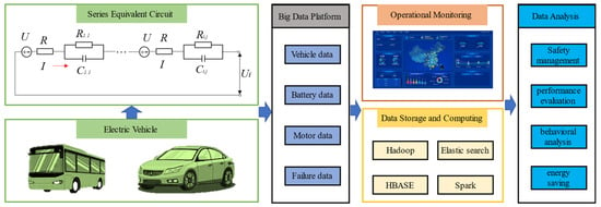
Figure 1.
Cloud-based power battery big data platform.
The data stored in the cloud-based big data platform include various electrical parameters of batteries, such as the battery cell end voltage, battery module end voltage, current, SOC, etc. Additionally, other parameters like temperature, mileage, and so on are also recorded. The data are organized in a standardized time series format in which each row consists of a time stamp and its corresponding parameters. The data format is a standard time series; each line of data contains a time stamp and its corresponding parameters, and the time stamp interval is 10 s, in line with the national standard GB/T32960 [31]. The data are from the period from March 2020 to September 2021.
The battery module consists of 96 NCM811 Li-ion ternary batteries (LiNi0.8Co0.1Mn0.1O2). These cells are connected in series, and each cell operates in a voltage range of 3.5 V to 4.3 V. Since each module is connected in series, the current data flowing through each cell remain constant. The current data fluctuate greatly under the discharge condition, as shown in Figure 2, and it is difficult to determine the fault state of the battery through the current data. Regarding the temperature inside the battery module, due to a limited number of temperature probes, it can only be measured at 24 positions evenly distributed inside the module. As a result, it is not possible to measure the temperature of each battery cell which, together with the hysteresis of temperature parameters compared to electrical signals, makes the localization of early failures using temperature difficult to achieve at this stage.
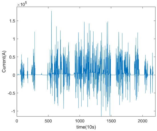
Figure 2.
Vehicle battery data under discharge conditions.
This paper focuses on analyzing various battery system faults, specifically micro-short-circuit faults, severe internal short-circuit faults, battery inconsistency faults, and sampling circuit faults. It is important to note that non-electrical quantities such as temperature do not provide a visual representation of battery faults as they change slowly. Similarly, internal resistance and other parameters cannot be measured directly. Therefore, to estimate the state of a battery, additional data are required. In this study, the voltage value is chosen as the most sensitive and intuitive data for fault analysis and diagnosis. Figure 3 shows the voltage curves of three different types of faults which come from the typical fault data stored in the big data platform and have data characteristics typical of different types of faults.
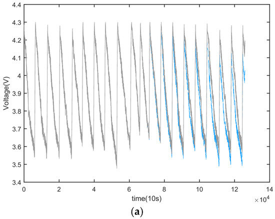
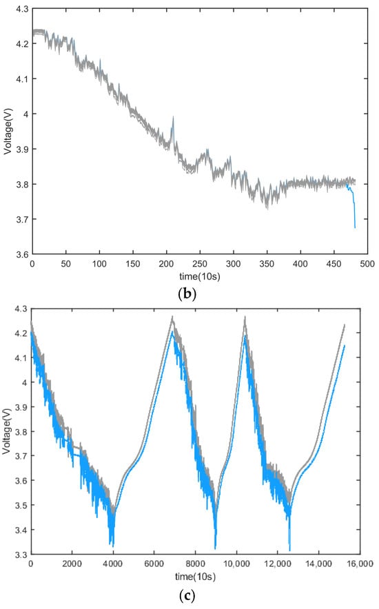
Figure 3.
Three common types of power battery failures. (a) Micro-short-circuit fault. (b) Severe internal short-circuit fault. (c) Battery inconsistency failure.
For the short-circuit fault within a battery, a first-order equivalent model of the battery can be used to analyze the fault, as follows:
where denotes the battery’s terminal voltage, denotes the battery’s open circuit voltage, denotes the battery’s equivalent capacitance–voltage, denotes the circuit current, and is the equivalent resistance. A schematic diagram of the first-order equivalent model of the battery is shown in Figure 4.
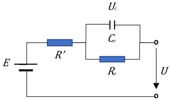
Figure 4.
First-order equivalent model of the battery.
When an internal short circuit occurs in a battery, the resistance value of the equivalent resistance decreases; as a result, the voltage at the end of the battery will drop. As shown in Figure 3a, when a micro-short circuit occurs in a battery, the voltage drop is not obvious and is difficult to observe directly, while when the battery has a serious internal short circuit, as shown in Figure 3b, its resistance value is lower, the voltage drops quickly, and the change in the voltage curve is more obvious. Therefore, distinguishing a battery’s micro-short circuit is more difficult compared to a serious internal short circuit. In the case of a severe internal short circuit, the impact is immediate and significant. Therefore, it is crucial to identify the faulty battery unit promptly to prevent any potential failure. It is more practical and effective to predict a fault before it occurs, rather than conducting a diagnosis after experiencing a failure.
Due to the scarcity of actual vehicle data and the rapid increase in battery fire incidents, it has become crucial to forecast severe internal short circuits well in advance, potentially even days before they occur. The causes of severe internal short circuits in batteries are multifaceted and can be attributed to thermal, electrical, or mechanical abuse, as well as defects in the battery manufacturing and assembly process. While micro-short circuits in batteries develop at a slower pace and cause less harm than serious internal shorts, there is still a potential for them to escalate to serious internal short circuits. Therefore, diagnosing micro-short circuits is essential for providing timely fault information to owners and manufacturers. This information can facilitate battery replacement and maintenance, ensuring the safety of owners. In this study, the focus will be on diagnosing this specific type of fault.
Unlike an internal short circuit, when there is inconsistency within a battery module, the voltages in some cells will be lower than in other battery singles, as shown in Figure 3c. This is caused by differences in parameters such as the internal resistance of the cells, the resistance of the connections, power, and capacity. As shown in Figure 5, under initial conditions, the rated capacity of cell A is low, and the initial SOC of cell C is low. During the discharge process, the inconsistency in the SOC will lead to an inconsistent voltage in the battery cells, which will lead to the over-discharge phenomenon occurring in battery C at the discharge cut-off, and the over-charge phenomenon will occur for battery A with a low initial capacity when it is re-charged. The cause of this type of failure may be subtle differences in the battery manufacturing and formation processes or the different working conditions of the batteries. This type of failure is the most common type of power battery failure. Due to its widespread occurrence, many researchers fail to recognize it as a battery system failure as it does not impact normal battery usage. While battery inconsistency may not cause major damage, certain individual battery cells within a module may experience frequent over-charging and over-discharging, resulting in accelerated battery capacity degradation and potentially compromising safety. An important characteristic of battery module inconsistency, as illustrated by Formula (1), is that the voltage change trend remains relatively uniform when subjected to the same current.
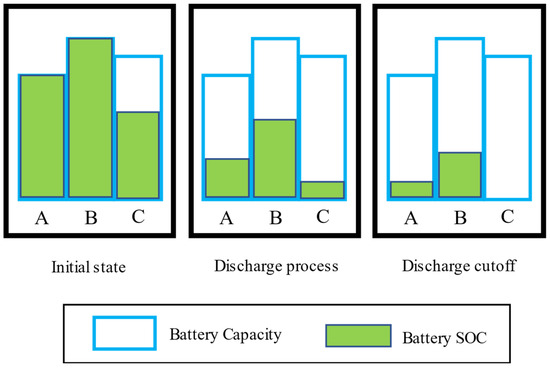
Figure 5.
Schematic diagram of battery module inconsistency.
3. Fault Diagnosis Method
3.1. Fault Characterization Indicators
To identify the fault characteristics present in voltage data, it is necessary to abstract the a priori knowledge associated with power battery faults into a parameter that can effectively represent these faults. Given the variety of power battery faults that can occur in real-world operating conditions, the external characterization of each fault type will differ to some extent. Therefore, a fault feature characterization formula has been proposed for various fault types, as illustrated in Table 1.

Table 1.
Commonly used fault characteristics.
Both the extended Root Mean Square Error (RMSE) and the Euclidean metric are distance-based fault characterization formulas. These formulas are effective in identifying the consistency evolution process in power battery modules and can also detect changes in faults after a certain delay when a micro-short-circuit fault occurs in the battery. However, when dealing with batteries that have poor battery consistency, these formulas may not produce ideal results. In such cases, additional processing methods are required to correct the results and eliminate the interference of battery consistency in the diagnosis results.
Both cosine similarity and the Pearson correlation coefficient are mathematical formulas used to measure the similarity between two vectors. These methods are commonly used to determine the voltage condition of a battery, making them useful for the early detection of battery failures. However, it is important to note that these methods can be affected by data fluctuations when applied in real-vehicle conditions. Additionally, the accuracy of these methods relies heavily on the quality of the data collected during the battery charging process. In instances in which the battery data have a high level of randomness during the discharging process, the effectiveness of these methods may be diminished.
The method of using information entropy for battery fault diagnosis relies primarily on the data characteristics of the battery unit itself. It assesses battery faults by analyzing changes in the data vertically and comparing them horizontally with other battery units in the battery module. This method is particularly sensitive to battery waveform data and is effective in identifying minor fluctuations and faults in the early stages of battery failure. However, it is also impacted by the quality of the data, which limits its robustness in real-vehicle conditions.
3.2. LOF Algorithm
The power battery fault diagnosis method for electric vehicles typically relies on comparing individual cells within the battery module. This comparison serves as a basis for discrimination. Electric vehicle batteries typically consist of the same types of battery cells connected in series and parallel. When these batteries are subjected to the same external excitation, the voltage change in the same type of battery should follow a normal distribution [34]. Hence, any battery unit that falls outside the probability range of the normal distribution can be considered anomalous.
However, comparing differences between cells cannot be the sole criterion for determining battery failure. When a battery fails, its deviation from historical operating conditions in terms of electrical quantity should also be taken into account. Therefore, when designing fault diagnosis methods, it is essential to consider multiple fault characteristic indicators simultaneously.
The literature [33] discusses how the calculated values of the extended root mean square error can be mapped in a two-dimensional coordinate space. This transformation allows the data variation, initially expressed in a one-dimensional space, to be represented using two-dimensional space coordinates. As a result, fault features at different time scales can be effectively fused. Building on this approach, multiple fault feature indicators can also be mapped to a higher-dimension coordinate space, following the same format. This enables the fusion of multidimensional fault features.
The Local Outlier Factor (LOF) [35] algorithm is an unsupervised anomaly detection algorithm that identifies anomalous data by comparing the density of data points. Unlike other algorithms, the LOF calculates a factor for each object that indicates its degree of outlierness rather than simply classifying it as normal or an outlier. As a result, the LOF performs well in detecting outliers in high-dimensional data spaces. Therefore, it is a suitable algorithm for identifying outliers in such spaces.
The precise description of local outlier factors is based on several definitions.
Definition 1.
The k-distance of
In dataset D, the distance between object and object is denoted as . For any positive integer k, the k-distance of an object p is denoted as . , satisfying the following conditions, is equal to .
There exist at least k objects satisfying.
There exist at most k-1 objects satisfying.
For denser areas, the value of is smaller; for less dense areas, the value of is larger.
Definition 2.
The k-distance neighborhood of
The k-distance neighborhood of an object is the set of all objects whose distance to does not exceed the k-distance, defined by the following formula.
Definition 3.
The reachable distance of
Assuming that is a natural number, the reachable distance of object about object o is defined as follows:
According to this definition, the reachable distances (k = 4) of object and object about object in Figure 6 are equal.
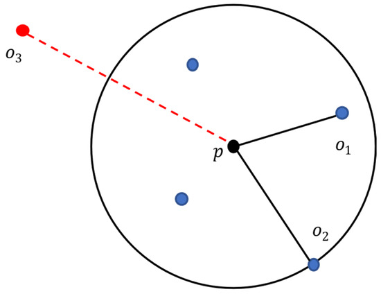
Figure 6.
Reachable distance diagram.
Definition 4.
The local reachable density of
Assuming that is a positive integer, the locally reachable density of object is defined as follows:
The local reachable density of object is the inverse of the average local reachable distance of the k-nearest neighbors of object . If object has a high degree of outlying, i.e., few near neighbors in its surrounding region, then its k-distance neighborhood has a wide coverage. For an object o within the k-distance neighborhood of , the probability that object is within the k-distance neighborhood of object is small, and has a higher probability of taking . Conversely, if object lies in a cluster of classes, the probability that object is within the k-distance neighborhood of object o is large for object o within the k-distance neighborhood of p, and has a higher probability of taking . Based on the analysis above, it is evident that outlier objects have small local reachable densities, while the local reachable densities of objects in class clusters are close and have larger values. In other words, local reachable densities provide insight into the density of local spatial regions within a dataset.
Definition 5.
The local outlier factors of .
The local outlier factor for object is defined as follows:
If point is a point with a large outlier degree, its local reachable distance is small, while the local reachable distances of the objects in its neighborhood are large, i.e., the LOF of point is large. On the contrary, if point is an object in a taxon, the difference between the locally reachable distance of point and the objects in its neighborhood is small, i.e., the LOF value of point is close to 1. This feature eliminates the effect of density differences among different taxa. An illustration of the local outlier calculation procedure for anomaly detection, based on the definition of the LOF, is presented in Figure 7.
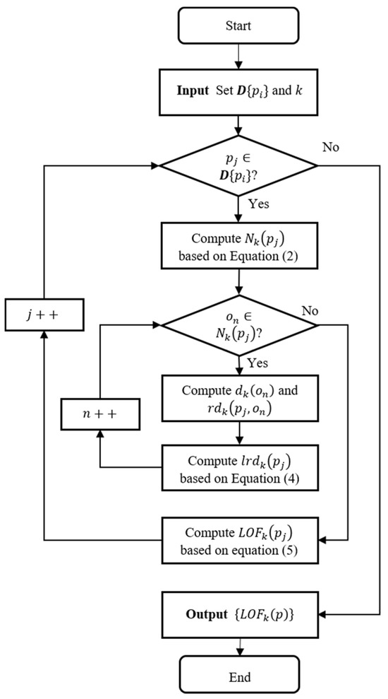
Figure 7.
The process of calculating the outlier factors.
During the operation of an electric vehicle’s battery module, the parameter changes in each battery unit inside it may not be synchronized at all times. This lack of synchronization can be attributed to signal transmission delays and current limitations of the hardware, which remain unresolved for the time being. Changes in battery monomer data often exhibit distinct differences between groups. In other words, the trend in battery monomer changes is generally more consistent within each group but inconsistent between groups. Traditional anomaly detection algorithms typically define anomalies as small numbers of outliers. However, when applied to actual operational data for power batteries, these methods may generate false reports due to significant fluctuations in the data. In contrast, the LOF algorithm utilizes cluster density as a discriminator, thereby identifying data points with genuine anomalies and theoretically reducing the likelihood of false positives.
3.3. Fault Diagnosis Process
The implementation process of the power battery fault diagnosis method incorporating multidimensional fault features is shown in Figure 8.
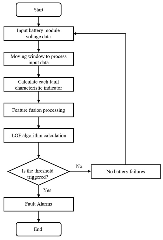
Figure 8.
Fault diagnosis flow chart.
Step 1: Extract the battery pack voltage data, i.e., , where M is the number of individual cells in the battery pack. A moving window is used to filter the data for processing the data stream.
Step 2: The fault feature parameters are calculated separately according to different fault feature calculation formulas to obtain different fault feature sequences , where T denotes the number of moving window moves and the fault feature sequences contain the Euclidean metric, Pearson correlation coefficient, information entropy, extended RMSE, and cosine similarity.
Step 3: According to the fault feature, the sequence is converted into coordinates; at this time, M five-dimensional spatial coordinate points . At this point, the fault diagnosis problem is converted into an anomaly identification problem with five-dimensional spatial coordinate points where denote the calculated values containing the Euclidean metric, Pearson correlation coefficient, information entropy, extended RMSE, and cosine similarity within the moving window, respectively. To facilitate the uniform calculation of data in each dimension, the calculated results of the above features are further processed using the Z-score normalization method. The formula for calculating the Z-score is as follows:
where denotes the eigenvalue sequence, denotes the length of the eigenvalue sequence, and denotes the eigenfinger sequence after Z-score normalization.
Step 4: Using the above coordinate points as input values for the LOF algorithm, the LOF algorithm is used to calculate the abnormal value for each coordinate point. The result this calculation for a normal vehicle is used as the basis for setting the threshold value to ensure that the calculation result of this algorithm will not issue a fault alarm under normal conditions.
The fault judgment criterion is shown in Equation (7): if the fault feature exceeds the threshold , an alarm signal is issued for the next judgment; if the fault feature does not exceed the threshold , no alarm signal is issued, and the next cycle is entered.
4. Fault Diagnosis Based on Real Vehicle Data
To verify the effectiveness of the proposed method discussed in this paper, historical data from the onboard power battery of an electric vehicle currently in use were employed for testing purposes. The aforementioned data were obtained from the most recent discharge cycle preceding the sampling cutoff. The sampling interval is 10 s, and the voltage resolution is 1 mV. Figure 9 contains the battery voltage data of two electric vehicles within the occurrence of a failure cycle, which were derived from a cloud-based big data platform.
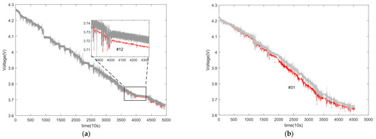
Figure 9.
Battery pack voltage variation curve. (a) Car 1. (b) Car 2.
Figure 9 shows the voltage variation curve for each battery cell in the battery pack during the electric vehicle’s operation. The curve represents 96 battery cells connected in series. The gray curve represents the voltage of normal, fault-free battery cells, while the red curve represents the voltage of cells experiencing a fault. From Figure 9, it is evident that battery cell #12 in car 1′s battery pack and battery cell #31 in car 2 both experienced early internal short-circuit faults. It is worth noting that the voltage variation curves exhibit random perturbations under actual operating conditions, which could potentially impact the accuracy of the fault identification method.
To verify the effectiveness of the method proposed in this paper, we will first analyze how the parameters extracted from different feature indicators distinguish battery failure, using car 2 as an example. A moving window length of 50 is used, and the tolerance in the extended RMSE method is set to 0.5. Figure 10 shows the results of applying the information entropy method to car 2. The blue curves represent the upper and lower limits of the 3σ threshold, while the red curve represents the curve of the faulty battery.
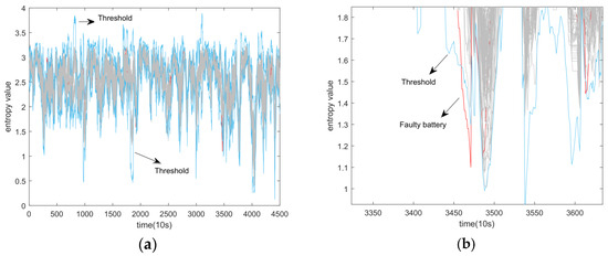
Figure 10.
Application of information entropy method on car 2. (a) original figure. (b) local enlarged figure.
The horizontal coordinate in Figure 10 indicates the sampling time point with a sampling interval of 10 s, and the vertical coordinate is the calculated value of information entropy. From Figure 10, it can be seen that the information entropy method does not have a significant advantage in fault discrimination until the faulty battery is identified at the 3460th sampling point. This identification occurs well after a significant drop in battery voltage. However, the method does not produce any false alarm cases within a reasonable threshold setting range. Additionally, although the fault diagnosis results in a significant delay, this delay does not negatively impact the fault results in the case of multidimensional fusion.
Both Figure 11 and Figure 12 contain curves of the original computed results as well as curves of the results after Z-score processing. The curves in red are known as faulty cell curves. Figure 11 depicts the results obtained from the cosine similarity method applied to car 2. The outcomes reveal that this method effectively differentiates faulty battery singletons between the 300th and 350th sampling points despite significant differences being observed. In contrast, Figure 10a shows that a single threshold value fails to trigger the threshold alarm for the faulty battery monomer #31.
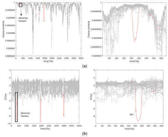
Figure 11.
Application of cosine similarity method on car 2. (a) Original calculation results. (b) Calculated results after normalization of Z-score.
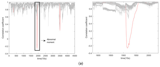
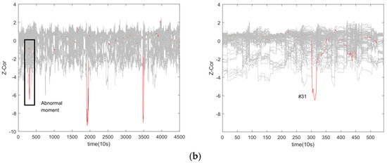
Figure 12.
Application of correlation coefficient method on car 2. (a) Original calculation results. (b) Calculated results after normalization of Z-score.
When examining the correlation coefficient method on car 2 (as seen in Figure 12), similar results to the cosine similarity method are observed. However, this method is less sensitive to data fluctuations, making it unable to accurately identify faulty cells in the early stages of the fault without employing Z-score normalization. After Z-score normalization, the eigenvalue calculations are unified to a common scale, as illustrated in Figure 11b and Figure 12b. Thus, both methods can discriminate anomalous data using a single threshold value.
Figure 13 and Figure 14 demonstrate the use of the extended RMSE method and the Euclidean metric on car 2, respectively. These methods are both distance-based, resulting in a similar overall trend in the calculated results. However, the extended RMSE method is more sensitive to faults due to its tolerance parameter settings, which leads to higher calculated values for faulty cells. Like the cosine similarity method, the distance-based method can identify faulty cells by using a single threshold at the 350th sampling point.
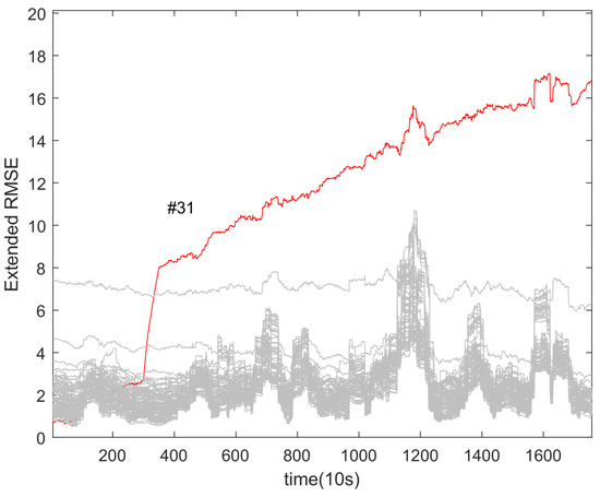
Figure 13.
Application of extended RMSE method on car 2.
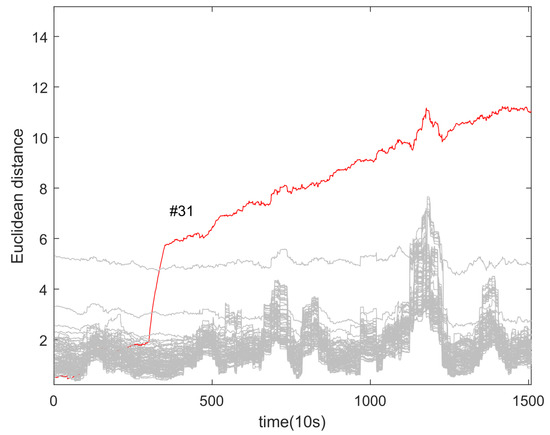
Figure 14.
Application of Euclidean metric on car 2.
After converting the above fault characteristic indicators, the results of the LOF algorithm are used to calculate the abnormalities in car 1 and car 2. These results can be seen in Figure 15 and Figure 16. For the LOF algorithm, the proximity point parameter is set to 10. In Figure 15, the red dashed line represents the fault threshold, while the red curve represents the LOF value curve of battery #31, which is the faulty battery. By using the threshold value, the single cell of battery #31 in car 2 can be correctly triggered at the 318th sampling point. In Figure 16, the LOF value curve for battery #12 correctly triggers the threshold at the 4844th sampling point, indicating an alarm. To avoid inconsistencies in threshold adjustment across different cars, the outlier threshold value is uniformly set at 7.5. This allows batteries with slightly less consistency to avoid falsely triggering the threshold. Typically, a certain number of fault data points are used as training objects to set thresholds and meet the requirements of various application scenarios. In this study, car 2 was used to provide training data for the threshold adjustment, while car 1 was used to provide test data to verify the feasibility of the threshold setting. Results from real car data demonstrate that this method can be appropriately applied across different cars.
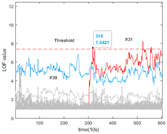
Figure 15.
Car 2: LOF algorithm calculation results.
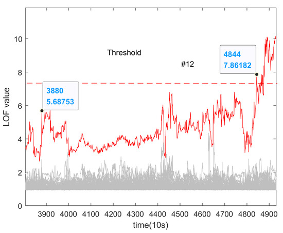
Figure 16.
Car 1: LOF algorithm calculation results.
It is important to mention that if a certain threshold is set, there will be a slight delay in the fault diagnosis results. However, this delay is still considered acceptable. When it comes to early internal short-circuit faults in car 1, it is challenging to accurately locate these faults using conventional methods. This is because the voltage drop in the faulty cell is not noticeable, and changes in the voltage drop are less obvious. Thankfully, after implementing the LOF algorithm to detect outliers, we can gradually identify the outliers of faulty cell #12 as the fault progresses.
To reflect the state-of-the-art method proposed in this paper, the power battery fault diagnosis method using a differential method to deal with extended RMSE [33] features is added as a comparison experiment. The method is also applicable to power battery fault diagnosis in real-vehicle conditions, but it uses only one dimension of indicators as a feature extraction method. Its experimental results are shown in Figure 17 and Figure 18. In this method, the original calculation of the LOF value is negative, which is the same as the realization of the method used in this paper. The method detects the fault in car 2 at 351 sampling points, with a delay of 330 s in detection time compared to the method proposed in this paper. In car 1, the fault was detected at the 4114th sample point. At the 3880th sample point, the proposed method can also detect the fault, but it needs to consider the fault alarm margin, so the threshold needs to be set as large as possible to minimize false fault alarms in extreme cases. When the threshold is set lower, the proposed method can detect the fault 2340 s earlier than the extended RMSE method. In the extended RMSE method, the threshold value is set low, which improves the sensitivity of fault detection but still lacks robustness. Taken together, the method proposed in this paper outperforms the extended RMSE method in terms of detection time, with an average improvement of 22 min. The results of a detailed comparison with other methods are shown in Table 2, which compares the ability to detect faults with the time to detect faults and robustness. The results show that the method proposed in this paper ensures the accuracy of detecting faults while improving robustness, which verifies the feasibility of applying the method in real working conditions.
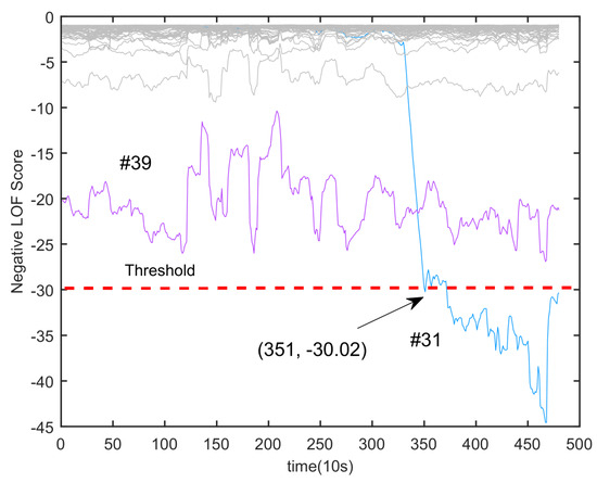
Figure 17.
Car 2: Extend RMSE LOF algorithm calculation results.
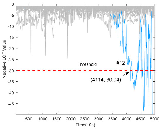
Figure 18.
Car 1: Extend RMSE LOF algorithm calculation results.

Table 2.
Comparison of test results from different methods using real vehicle data.
In an ideal state, conventional fault diagnosis methods such as the correlation coefficient method and information entropy method are not affected by data fluctuations, and they can accurately determine the occurrence of faults. However, in a non-ideal state, the data fluctuation of the power battery will cause these methods to produce frequent false alarms. The method proposed in this paper combines parts of fault extraction from traditional methods so that it can cope with various types of faults under ideal conditions. However, data fluctuations in real situations can cause them to experience frequent false alarms, so in the process of setting the threshold, although we only used the battery data of car 2 as a training object, the battery data of car 2 contain battery data under normal conditions and data under abnormal conditions. In the battery data under normal conditions, there are not only normal battery voltage data but also many sampling errors with large fluctuation conditions. These rough data were used for training during the threshold-setting process, making it possible to maximize the fault diagnosis process without false alarms. Similarly, we performed training with data from car 1 and validation with data from car 2 to achieve the same effect.
5. Conclusions and Outlook
To ensure the accuracy and reliability of power battery fault diagnosis in real-vehicle conditions, this paper proposes a multidimensional feature fusion fault diagnosis method. The difficulty of this process is in ensuring that faults are detected and no false alarms occur for normal conditions. Therefore, the method proposed in this paper combines multiple classical features; this sacrifices part of the detection time to improve robustness, but after a comparison, it was found that the detection time is still less than that of the extended RMSE method, which has practical value. Compared with other methods, this method has the best performance in practical application scenarios.
To further reduce the fault detection time, data accuracy needs to be further improved. After the data sampling frequency is increased to 1 Hz or even 10 Hz, the data will contain more high-dimensional information, and the data will be smoother. Therefore, the correlation coefficient-based method may be less affected by data fluctuations, and as the method has the highest sensitivity to data anomalies, it will perform quite well in this case. After the further accumulation of valid fault data, the establishment of a fault diagnosis model based on a neural network model is urgently needed.
Author Contributions
Methodology, F.Z.; Validation, M.W.; Data curation, Z.X.; Writing—review & editing, X.Z. All authors have read and agreed to the published version of the manuscript.
Funding
This research was funded by Natural Science Foundation of Hubei Province: 2022CFA007; Science and Technology Project of Hubei Province: 2022BEC017; Science and Technology Project of Hubei Province: 2022BEB016.
Data Availability Statement
The original contributions presented in the study are included in the article, further inquiries can be directed to the corresponding author.
Conflicts of Interest
The authors declare no conflict of interest.
References
- Finegan, D.P.; Darst, J.; Walker, W.; Li, Q.; Yang, C.; Jervis, R.; Heenan, T.M.M.; Thomas, J.C.; Rack, A.; Jervis, R.; et al. Modelling and experiments to identify high-risk failure scenarios for testing the safety of lithium-ion cells. J. Power Sources 2019, 417, 29–41. [Google Scholar] [CrossRef]
- Han, X.; Lu, L.; Zheng, Y.; Feng, X.; Li, Z.; Li, J.; Ouyang, M. A review on the key issues of the lithium ion battery degradation among the whole life cycle. eTransportation 2019, 1, 100005. [Google Scholar] [CrossRef]
- Deng, Y.; Wang, C.-P.; Xiao, Y.; Chen, H.-L.; Deng, J.; Du, Y.-X.; Bai, G.-X. Effect of greenhouse gases emissions from coal spontaneous combustion under different inerting conditions in the quenching process. J. Therm. Anal. Calorim. 2023, 148, 4883–4895. [Google Scholar] [CrossRef]
- Wang, Y.; Feng, X.; Huang, W.; He, X.; Wang, L.; Ouyang, M. Challenges and Opportunities to Mitigate the Catastrophic Thermal Runaway of High-Energy Batteries. Adv. Energy Mater. 2023, 13, 2203841. [Google Scholar] [CrossRef]
- Xia, B.; Chen, Z.; Mi, C.; Robert, B. External short circuit fault diagnosis for lithium-ion batteries. In Proceedings of the 2014 IEEE Transportation Electrification Conference and Expo, Dearborn, MI, USA, 15–18 June 2014; pp. 1–7. [Google Scholar]
- Lyu, D.; Ren, B.; Li, S. Failure modes and mechanisms for rechargeable Lithium-based batteries: A state-of-the-art review. Acta Mech. 2019, 230, 701–727. [Google Scholar] [CrossRef]
- Shen, D.; Lyu, C.; Yang, D.; Hinds, G.; Wang, L. Connection fault diagnosis for lithium-ion battery packs in electric vehicles based on mechanical vibration signals and broad belief network. Energy 2023, 274, 127291. [Google Scholar] [CrossRef]
- Hu, X.; Liu, W.; Lin, X.; Xie, Y. A Comparative Study of Control-Oriented Thermal Models for Cylindrical Li-Ion Batteries. IEEE Trans. Transp. Electrif. 2019, 5, 1237–1253. [Google Scholar] [CrossRef]
- Hu, X.; Zhang, K.; Liu, K.; Lin, X.; Dey, S.; Onori, S. Advanced fault diagnosis for lithium-ion battery systems: A review of fault mechanisms, fault features, and diagnosis procedures. IEEE Ind. Electron. Mag. 2020, 14, 64–91. [Google Scholar] [CrossRef]
- Yu, Q.; Wang, C.; Li, J.; Xiong, R.; Pecht, M. Challenges and outlook for lithium-ion battery fault diagnosis methods from the laboratory to real world applications. eTransportation 2023, 17, 100254. [Google Scholar] [CrossRef]
- Jin, H.; Gao, Z.; Zuo, Z.; Zhang, Z.; Wang, Y.; Zhang, A. A Combined Model-Based and Data-Driven Fault Diagnosis Scheme for Lithium-Ion Batteries. IEEE Trans. Ind. Electron. 2023, 71, 6274–6284. [Google Scholar] [CrossRef]
- Liu, X.Q.; Zhang, H.Y. Fault detection and diagnosis of permanent-magnet DC motor based on parameter estimation and neural network. IEEE Trans. Ind. Electron. 2000, 47, 1021–1030. [Google Scholar]
- Odendaal, H.M.; Jones, T. Actuator fault detection and isolation: An optimised parity space approach. Control Eng. Pract. 2014, 26, 222–232. [Google Scholar] [CrossRef]
- Seo, M.; Goh, T.; Park, M.; Koo, G.; Kim, S.W. Detection of internal short circuit in lithium ion battery using model-based switching model method. Energies 2017, 10, 76. [Google Scholar] [CrossRef]
- Liu, Z.; Ahmed, Q.; Zhang, J.; Rizzoni, G.; He, H. Structural analysis-based sensors fault detection and isolation of cylindrical lithium-ion batteries in automotive applications. Control Eng. Pract. 2016, 52, 46–58. [Google Scholar] [CrossRef]
- Zhao, G.; Kang, Y.; Huang, P.; Duan, B.; Zhang, C. Battery health prognostic using efficient and robust aging trajectory matching with ensemble deep transfer learning. Energy 2023, 282, 128228. [Google Scholar] [CrossRef]
- Wu, C.; Zhu, C.; Ge, Y. A new fault diagnosis and prognosis technology for high-power lithium-ion battery. IEEE Trans. Plasma Sci. 2017, 45, 1533–1538. [Google Scholar] [CrossRef]
- Sidhu, A.; Izadian, A.; Anwar, S. Adaptive Nonlinear Model-Based Fault Diagnosis of Li-Ion Batteries. IEEE Trans. Ind. Electron. 2015, 62, 1002–1011. [Google Scholar] [CrossRef]
- Chen, Z.; Xiong, R.; Tian, J.; Shang, X.; Lu, J. Model-based fault diagnosis approach on external short circuit of lithium-ion battery used in electric vehicles. Appl. Energy 2016, 184, 364–374. [Google Scholar] [CrossRef]
- Yang, R.; Xiong, R.; He, H.; Chen, Z. A fractional-order model-based battery external short circuit fault diagnosis approach for all-climate electric vehicles application. J. Clean. Prod. 2018, 187, 950–959. [Google Scholar] [CrossRef]
- Dey, S.; Biron, Z.A.; Tatipamula, S.; Das, N.; Mohon, S.; Ayalew, B.; Pisu, P. Model-based real-time thermal fault diagnosis of Lithium-ion batteries. Control Eng. Pract. 2016, 56, 37–48. [Google Scholar] [CrossRef]
- Gao, W.; Zheng, Y.; Ouyang, M.; Li, J.; Lai, X.; Hu, X. Micro-Short Circuit Diagnosis for Series-Connected Lithium-Ion Battery Packs Using Mean-Difference Model. IEEE Trans. Ind. Electron. 2018, 66, 2132–2142. [Google Scholar] [CrossRef]
- Ping, P.; Wang, Q.; Chung, Y.; Wen, J. Modelling electro-thermal response of lithium-ion batteries from normal to abuse conditions. Appl. Energy 2017, 205, 1327–1344. [Google Scholar] [CrossRef]
- Yang, L.; Gao, H.; Duan, H. Research on intelligent Diagnosis method of Electric vehicle Charging Fault based on artificial intelligence expert system. J. Phys. Conf. Ser. 2021, 1848, 012125. [Google Scholar] [CrossRef]
- Kong, X.; Zheng, Y.; Ouyang, M.; Lu, L.; Li, J.; Zhang, Z. Fault diagnosis and quantitative analysis of micro-short circuits for lithium-ion batteries in battery packs. J. Power Sources 2018, 395, 358–368. [Google Scholar] [CrossRef]
- Zhao, Y.; Liu, P.; Wang, Z.; Zhang, L.; Hong, J. Fault and defect diagnosis of battery for electric vehicles based on big data analysis methods—ScienceDirect. Appl. Energy 2017, 207, 354–362. [Google Scholar] [CrossRef]
- Xia, B.; Shang, Y.; Nguyen, T.; Mi, C. A correlation-based fault detection method for short circuits in battery packs. J. Power Sources 2017, 337, 1–10. [Google Scholar] [CrossRef]
- Kang, Y.; Duan, B.; Zhou, Z.; Shang, Y.; Zhang, C. Online multi-fault detection and diagnosis for battery packs in electric vehicles. Appl. Energy 2020, 259, 114170.1–114170.16. [Google Scholar] [CrossRef]
- Wang, Z.; Hong, J.; Liu, P.; Zhang, L. Voltage fault diagnosis and prognosis of battery systems based on entropy and Z-score for electric vehicles. Appl. Energy 2017, 196, 289–302. [Google Scholar] [CrossRef]
- Du, W.; Chen, J.; Xing, Z.; Zhang, F.; Wu, M. Battery fault diagnosis and thermal runaway warning based on the Feature-Exponential-Function and Dynamic Time Warping method. J. Energy Storage 2023, 72, 108236. [Google Scholar] [CrossRef]
- GB/T 32960.3-2016; Technical Specification for Remote Service and Management Systems for Electric Vehicles—Part 3: Communication Protocols and Data Formats. Standardization Administration Committee: Beijing, China, 2016.
- Wu, M.; Du, W.; Zhang, F.; Zhao, N.; Wang, J.; Wang, L.; Huang, W. Fault Diagnosis Method for Lithium-Ion Battery Packs in Real-World Electric Vehicles Based on K-Means and the Fréchet Algorithm. ACS Omega 2022, 7, 40145–40162. [Google Scholar] [CrossRef]
- Zhang, F.; Xing, Z.X.; Wu, M.H. Fault diagnosis method for lithium-ion batteries in electric vehicles using generalized dimensionless indicator and local outlier factor. J. Energy Storage 2022, 52, 104963. [Google Scholar]
- Salehen, P.M.W.; Su’ait, M.S.; Razali, H.; Sopian, K. Development of battery management systems (BMS) for electric vehicles (evs) in Malaysia. MATEC Web Conf. 2017, 90, 01001. [Google Scholar] [CrossRef]
- Bai, Y.Y.; Zou, S.B.; Ding-Gen, L.I. Abuse Fault Diagnosis Method of Power Battery System Based on Data Analysis Method. Adv. New Renew. Energy 2020, 8, 1–5. [Google Scholar]
Disclaimer/Publisher’s Note: The statements, opinions and data contained in all publications are solely those of the individual author(s) and contributor(s) and not of MDPI and/or the editor(s). MDPI and/or the editor(s) disclaim responsibility for any injury to people or property resulting from any ideas, methods, instructions or products referred to in the content. |
© 2024 by the authors. Licensee MDPI, Basel, Switzerland. This article is an open access article distributed under the terms and conditions of the Creative Commons Attribution (CC BY) license (https://creativecommons.org/licenses/by/4.0/).