


Review of Cell-Balancing Schemes for Electric Vehicle Battery Management Systems


 ,
,
Abstract
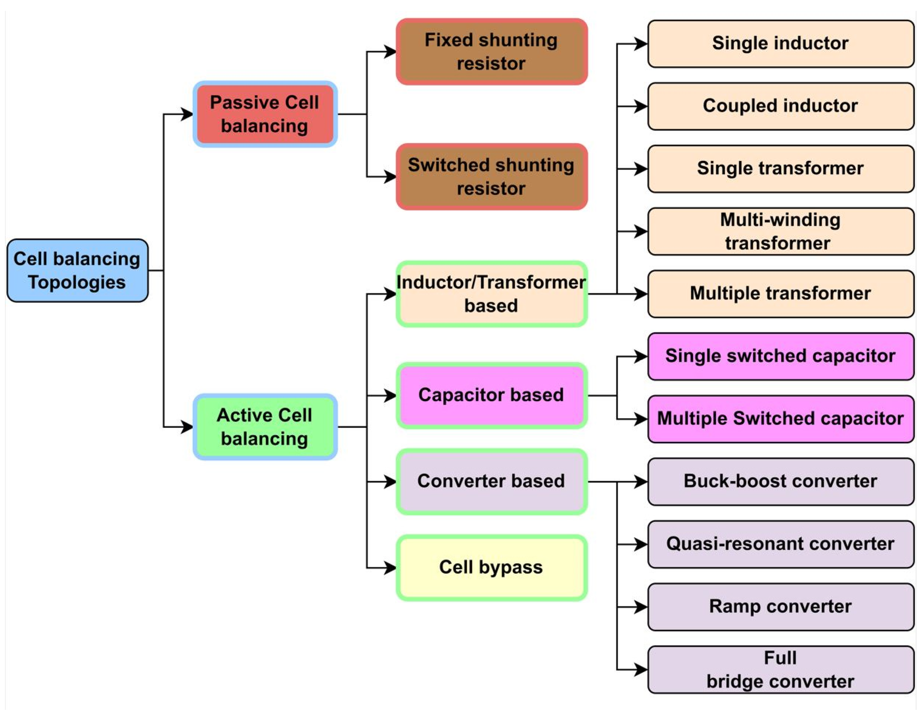
1. Introduction
2. Closed-Loop Switched-Capacitor Structure
3. Parallel Resonant Switched-Capacitor Equaliser
4. Single Inductor Bidirectional Cell Balancing
5. Coupled Inductor Cell Balancing
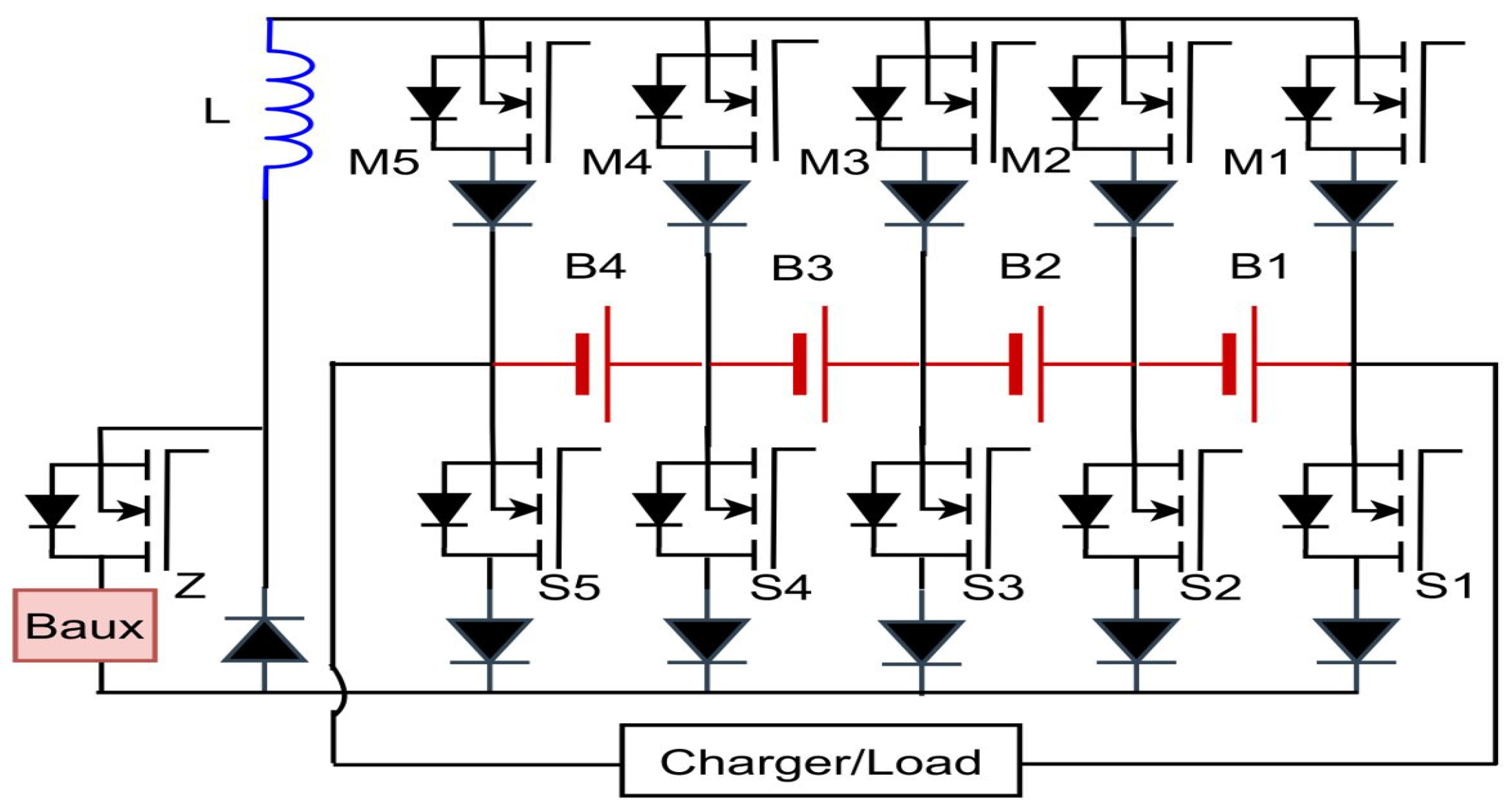
6. Single Inductor Cell Balancing with an Auxiliary Battery
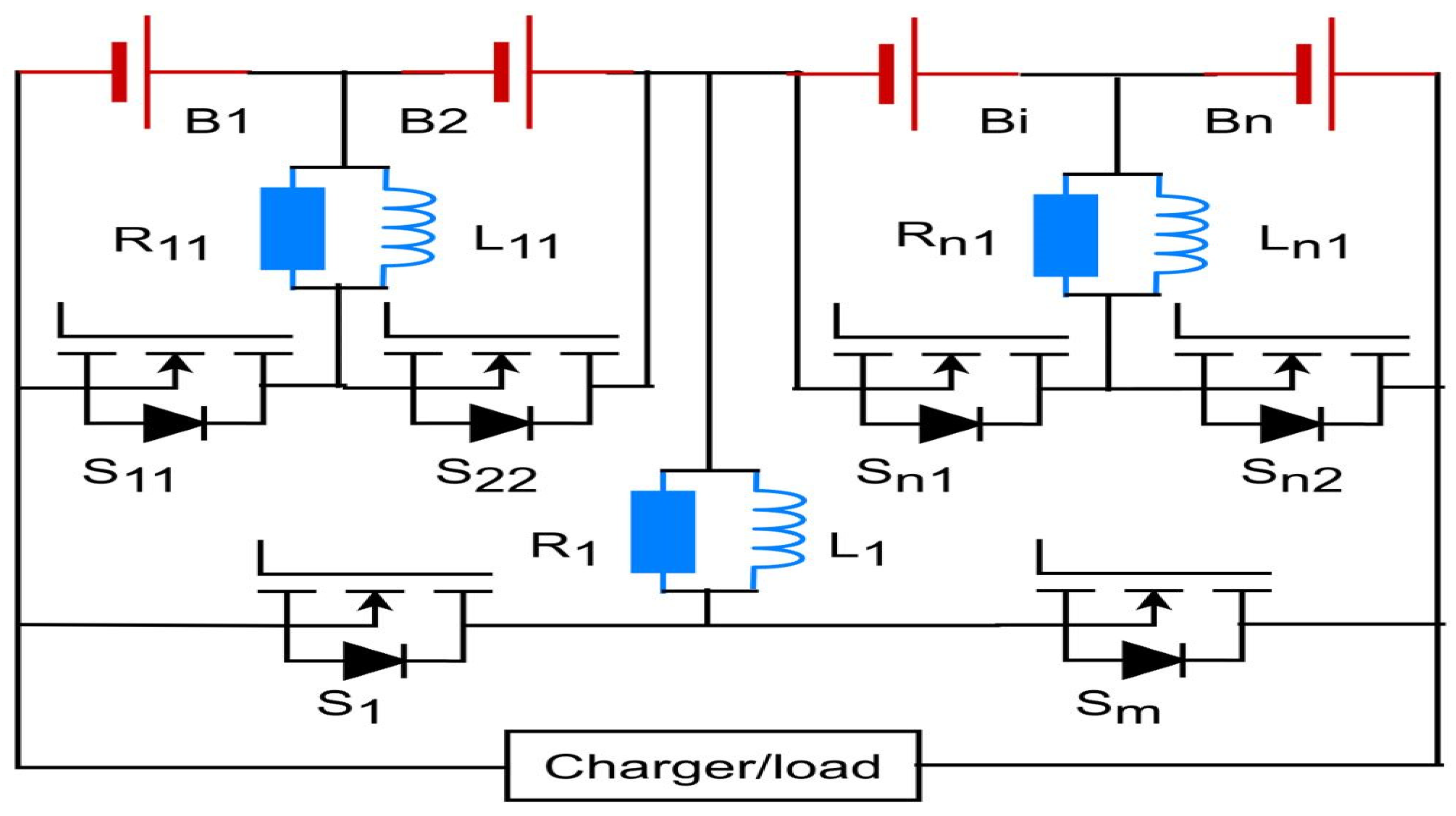
7. Double-Layer Inductive Equalisation Circuit
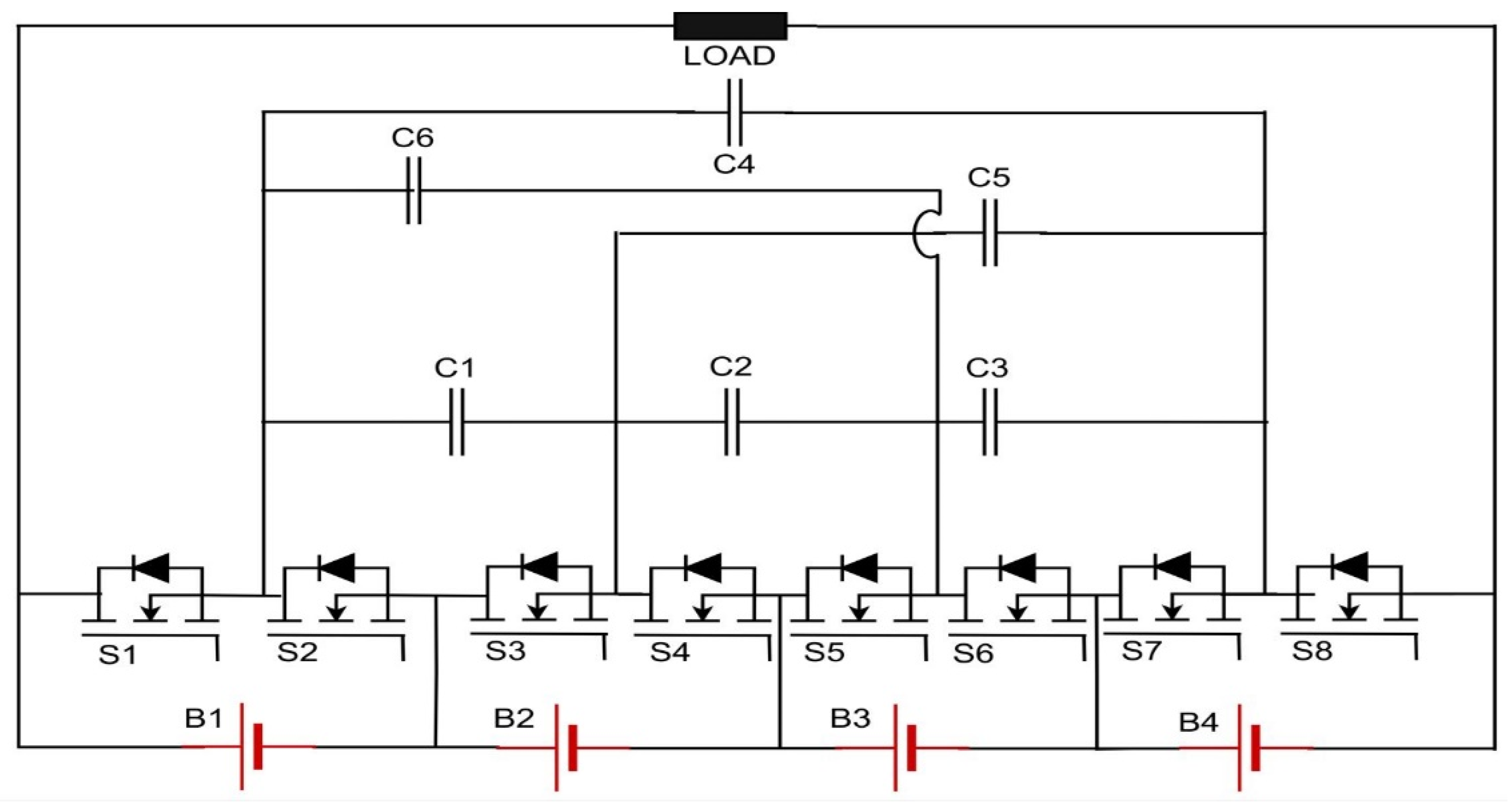
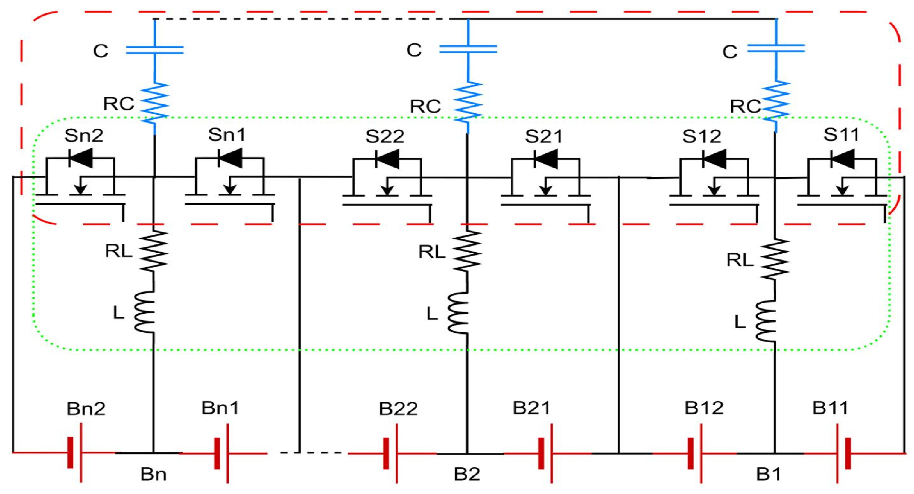
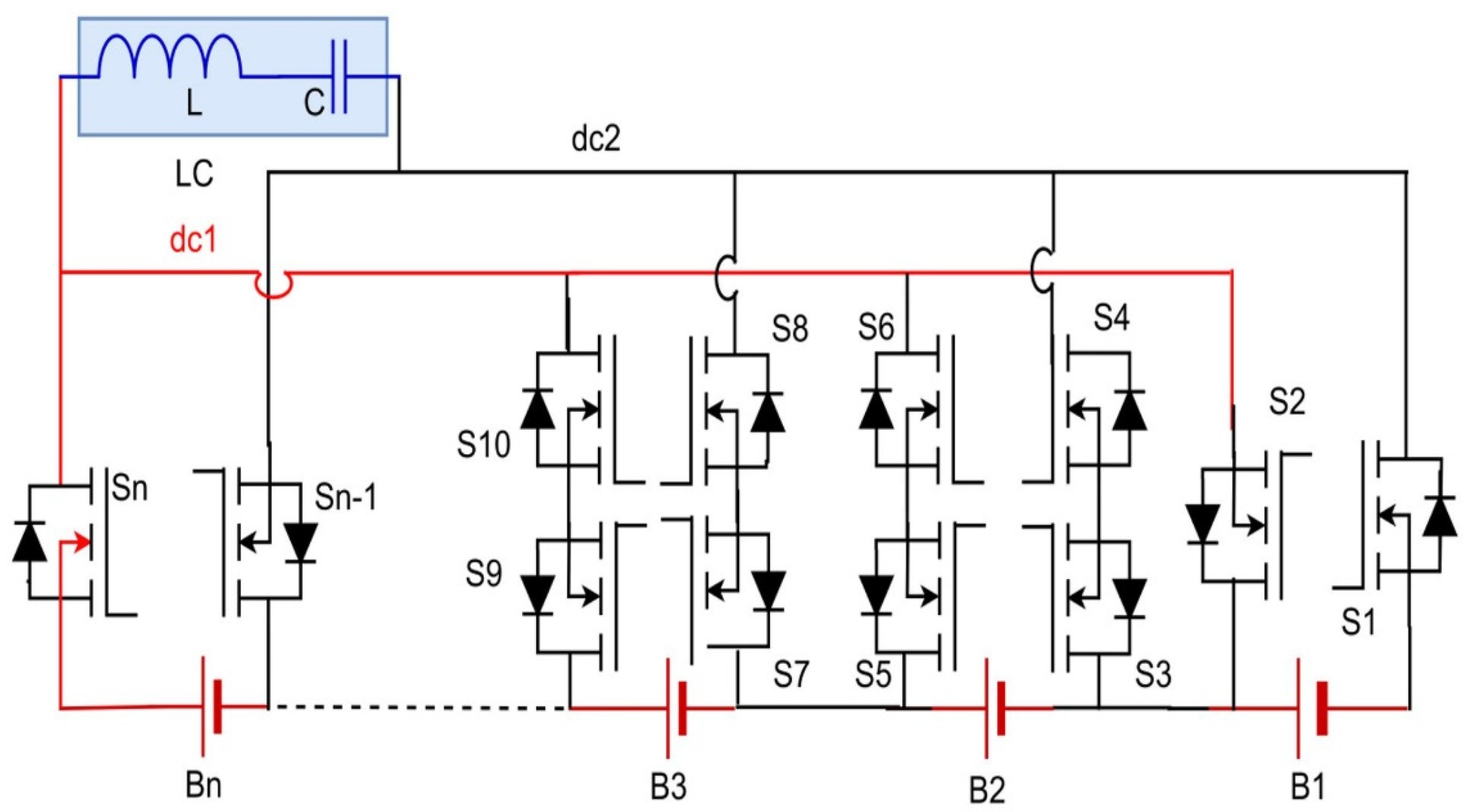
8. Advanced Switched-Capacitor Equaliser Circuit
- At the switching instances, the capacitor charging and discharging currents are extremely high.
- The voltage of the cells does not change significantly throughout one or more switching cycles. Here, if a fixed duty cycle of 50% is used with cells having different voltages and linked to a single inductor through the switches, the inductor volt-second balance law will not be satisfied, leading to a rise in the average inductor current.
- The balancing speed will drastically decrease if the number of series cells increases due to the utilisation of traditional switched-capacitor (SC)-based topology, which can only offer adjacent cell balancing.
9. Push-Pull Converter-Based Cell-Balancing Circuit
10. Dual DC-DC Converter-Based Cell Balancing with an Auxiliary Battery
11. Single Resonant Converter Balancing Circuit
12. Summary of Optimisation in Basic Cell-Balancing Topologies
13. Conclusions
Author Contributions
Funding
Data Availability Statement
Conflicts of Interest
References
- Lee, S.B.; Thiagarajan, R.S.; Subramanian, V.R.; Onori, S. Advanced Battery Management Systems: Modeling and Numerical Simulation for Control. In Proceedings of the 2022 American Control Conference (ACC), Atlanta, GE, USA, 8–10 June 2022; pp. 4403–4414. [Google Scholar]
- Altemose, G.; Hellermann, P.; Mazz, T. Active cell balancing system using an isolated share bus for Li-Ion battery management: Focusing on satellite applications. In Proceedings of the 2011 IEEE Long Island Systems, Applications and Technology Conference, Farmingdale, NY, USA, 6 May 2011; pp. 1–7. [Google Scholar]
- Hu, L.; Zhao, M.-L.; Wu, X.-B.; Lou, J.-N. Cell balancing management for battery pack. In Proceedings of the 2010 10th IEEE International Conference on Solid-State and Integrated Circuit Technology, Shanghai, China, 1–4 November 2010; pp. 339–341. [Google Scholar]
- Gabbar, H.A.; Othman, A.M.; Abdussami, M.R. Review of battery management systems (BMS) development and industrial standards. Technologies 2021, 9, 28. [Google Scholar] [CrossRef]
- Cadar, D.V.; Petreus, D.M.; Patarau, T.M. An energy converter method for battery cell balancing. In Proceedings of the 33rd International Spring Seminar on Electronics Technology, ISSE 2010, Warsaw, Poland, 12–16 May 2010; pp. 290–293. [Google Scholar]
- Shen, M.; Gao, Q. A review on battery management system from the modeling efforts to its multiapplication and integration. Int. J. Energy Res. 2019, 43, 5042–5075. [Google Scholar] [CrossRef]
- Wen, S. Cell balancing buys extra run time and battery life. Analog Appl. J. 2009, 1, 14–41. [Google Scholar]
- Liu, K.; Li, K.; Peng, Q.; Zhang, C. A brief review on key technologies in the battery management system of electric vehicles. Front. Mech. Eng. 2019, 14, 47–64. [Google Scholar] [CrossRef]
- Wang, Y.; Tian, J.; Sun, Z.; Wang, L.; Xu, R.; Li, M.; Chen, Z. A comprehensive review of battery modeling and state estimation approaches for advanced battery management systems. Renew. Sustain. Energy Rev. 2020, 131, 110015. [Google Scholar] [CrossRef]
- Lü, X.; Wu, Y.; Lian, J.; Zhang, Y.; Chen, C.; Wang, P.; Meng, L. Energy management of hybrid electric vehicles: A review of energy optimization of fuel cell hybrid power system based on genetic algorithm. Energy Convers. Manag. 2020, 205, 112474. [Google Scholar] [CrossRef]
- Wu, B.; Widanage, W.D.; Yang, S.; Liu, X. Battery digital twins: Perspectives on the fusion of models, data and artificial intelligence for smart battery management systems. Energy AI 2020, 1, 100016. [Google Scholar] [CrossRef]
- Dai, H.; Jiang, B.; Hu, X.; Lin, X.; Wei, X.; Pecht, M. Advanced battery management strategies for a sustainable energy future: Multilayer design concepts and research trends. Renew. Sustain. Energy Rev. 2021, 138, 110480. [Google Scholar] [CrossRef]
- İnci, M.; Büyük, M.; Demir, M.H.; İlbey, G. A review and research on fuel cell electric vehicles: Topologies, power electronic converters, energy management methods, technical challenges, marketing and future aspects. Renew. Sustain. Energy Rev. 2021, 137, 110648. [Google Scholar] [CrossRef]
- Ali, M.U.; Zafar, A.; Nengroo, S.H.; Hussain, S.; Junaid Alvi, M.; Kim, H.-J. Towards a smarter battery management system for electric vehicle applications: A critical review of lithium-ion battery state of charge estimation. Energies 2019, 12, 446. [Google Scholar] [CrossRef]
- Hemavathi, S. Overview of cell balancing methods for Li-ion battery technology. Energy Storage 2021, 3, e203. [Google Scholar]
- Thiruvonasundari, D.; Deepa, K. Optimized passive cell balancing for fast charging in electric vehicle. IETE J. Res. 2023, 69, 2089–2097. [Google Scholar] [CrossRef]
- Quraan, M.; Tricoli, P.; D’Arco, S.; Piegari, L. Efficiency assessment of modular multilevel converters for battery electric vehicles. IEEE Trans. Power Electron. 2016, 32, 2041–2051. [Google Scholar] [CrossRef]
- Hoekstra, F.S.J.; Ribelles, L.W.; Bergveld, H.J.; Donkers, M. Real-time range maximisation of electric vehicles through active cell balancing using model-predictive control. In Proceedings of the 2020 American Control Conference (ACC), Denver, CO, USA, 1–3 July 2020; pp. 2219–2224. [Google Scholar]
- Zhang, D.-H.; Zhu, G.-R.; He, S.-J.; Qiu, S.; Ma, Y.; Wu, Q.-M.; Chen, W. Balancing control strategy for li-ion batteries string based on dynamic balanced point. Energies 2015, 8, 1830–1847. [Google Scholar] [CrossRef]
- Hasan, M.K.; Mahmud, M.; Habib, A.A.; Motakabber, S.; Islam, S. Review of electric vehicle energy storage and management system: Standards, issues, and challenges. J. Energy Storage 2021, 41, 102940. [Google Scholar] [CrossRef]
- Borne, M.; Wen, S. Providing Active Cell Balancing in Battery Design. Texas Instruments. EE Times-India. Lehtiartikkeli. Saatavissa. 2009. Available online: http://eetindia.com (accessed on 3 January 2024).
- Lee, Y.; Jeon, S.; Lee, H.; Bae, S. Comparison on cell balancing methods for energy storage applications. Indian J. Sci. Technol. 2016, 9, 92316. [Google Scholar] [CrossRef]
- Hoque, M.; Hannan, M.; Mohamed, A.; Ayob, A. Battery charge equalization controller in electric vehicle applications: A review. Renew. Sustain. Energy Rev. 2017, 75, 1363–1385. [Google Scholar] [CrossRef]
- Vaideeswaran, V.; Bhuvanesh, S.; Devasena, M. Battery management systems for electric vehicles using lithium ion batteries. In Proceedings of the 2019 Innovations in Power and Advanced Computing Technologies (i-PACT), Vellore, India, 22–23 March 2019; Volume 1, pp. 1–9. [Google Scholar]
- Omariba, Z.B.; Zhang, L.; Sun, D. Review of battery cell balancing methodologies for optimizing battery pack performance in electric vehicles. IEEE Access 2019, 7, 129335–129352. [Google Scholar] [CrossRef]
- Hua, Y.; Zhou, S.; Cui, H.; Liu, X.; Zhang, C.; Xu, X.; Ling, H.; Yang, S. A comprehensive review on inconsistency and equalization technology of lithium-ion battery for electric vehicles. Int. J. Energy Res. 2020, 44, 11059–11087. [Google Scholar] [CrossRef]
- Habib, A.A.; Hasan, M.K.; Mahmud, M.; Motakabber, S.; Ibrahimya, M.I.; Islam, S. A review: Energy storage system and balancing circuits for electric vehicle application. IET Power Electron. 2021, 14, 1–13. [Google Scholar] [CrossRef]
- Carter, J.; Fan, Z.; Cao, J. Cell equalisation circuits: A review. J. Power Sources 2020, 448, 227489. [Google Scholar] [CrossRef]
- Das, U.K.; Shrivastava, P.; Tey, K.S.; Idris, M.Y.I.B.; Mekhilef, S.; Jamei, E.; Seyedmahmoudian, M.; Stojcevski, A. Advancement of lithium-ion battery cells voltage equalization techniques: A review. Renew. Sustain. Energy Rev. 2020, 134, 110227. [Google Scholar] [CrossRef]
- Turksoy, A.; Teke, A.; Alkaya, A. A comprehensive overview of the dc-dc converter-based battery charge balancing methods in electric vehicles. Renew. Sustain. Energy Rev. 2020, 133, 110274. [Google Scholar] [CrossRef]
- Uzair, M.; Abbas, G.; Hosain, S. Characteristics of battery management systems of electric vehicles with consideration of the active and passive cell balancing process. World Electr. Veh. J. 2021, 12, 120. [Google Scholar] [CrossRef]
- Anno, T.; Koizumi, H. Double-input bidirectional DC/DC converter using cell-voltage equalizer with flyback transformer. IEEE Trans. Power Electron. 2014, 30, 2923–2934. [Google Scholar] [CrossRef]
- Ye, Y.; Cheng, K.W.E.; Fong, Y.C.; Xue, X.; Lin, J. Topology, modeling, and design of switched-capacitor-based cell balancing systems and their balancing exploration. IEEE Trans. Power Electron. 2016, 32, 4444–4454. [Google Scholar] [CrossRef]
- Fukui, R.; Koizumi, H. Double-tiered switched capacitor battery charge equalizer with chain structure. In Proceedings of the IECON 2013-39th Annual Conference of the IEEE Industrial Electronics Society, Vienna, Austria, 10–13 November 2013; pp. 6715–6720. [Google Scholar]
- Singirikonda, S.; Obulesu, Y. Active cell voltage balancing of Electric vehicle batteries by using an optimized switched capacitor strategy. J. Energy Storage 2021, 38, 102521. [Google Scholar] [CrossRef]
- Ye, Y.; Cheng, K.W.E. Modeling and analysis of series–parallel switched-capacitor voltage equalizer for battery/supercapacitor strings. IEEE J. Emerg. Sel. Top. Power Electron. 2015, 3, 977–983. [Google Scholar] [CrossRef]
- Yuanmao, Y.; Cheng, K.W.E.; Yeung, Y. Zero-current switching switched-capacitor zero-voltage-gap automatic equalization system for series battery string. IEEE Trans. Power Electron. 2011, 27, 3234–3242. [Google Scholar] [CrossRef]
- Lee, K.-M.; Chung, Y.-C.; Sung, C.-H.; Kang, B. Active cell balancing of li-ion batteries using LC series resonant circuit. IEEE Trans. Ind. Electron. 2015, 62, 5491–5501. [Google Scholar] [CrossRef]
- Ye, Y.; Cheng, K.W.E. Analysis and design of zero-current switching switched-capacitor cell balancing circuit for series-connected battery/supercapacitor. IEEE Trans. Veh. Technol. 2017, 67, 948–955. [Google Scholar] [CrossRef]
- Pasternak, S.R.; Kiani, M.H.; Rentmeister, J.S.; Stauth, J.T. Modeling and performance limits of switched-capacitor DC–DC converters capable of resonant operation with a single inductor. IEEE J. Emerg. Sel. Top. Power Electron. 2017, 5, 1746–1760. [Google Scholar] [CrossRef]
- Kesarwani, K.; Sangwan, R.; Stauth, J.T. Resonant-switched capacitor converters for chip-scale power delivery: Design and implementation. IEEE Trans. Power Electron. 2014, 30, 6966–6977. [Google Scholar] [CrossRef]
- Liu, L.; Mai, R.; Xu, B.; Sun, W.; Zhou, W.; He, Z. Design of parallel resonant switched-capacitor equalizer for series-connected battery strings. IEEE Trans. Power Electron. 2021, 36, 9160–9169. [Google Scholar] [CrossRef]
- Shang, Y.; Zhang, C.; Cui, N.; Mi, C.C. A delta-structured switched-capacitor equalizer for series-connected battery strings. IEEE Trans. Power Electron. 2018, 34, 452–461. [Google Scholar] [CrossRef]
- Shang, Y.; Xia, B.; Zhang, C.; Cui, N.; Yang, J.; Mi, C.C. An automatic equalizer based on forward–flyback converter for series-connected battery strings. IEEE Trans. Ind. Electron. 2017, 64, 5380–5391. [Google Scholar] [CrossRef]
- Du, W.; Huang, X.; Yang, S.; Zhang, F.; Wu, X.; Qian, Z. A novel equalization method with defective-battery-replacing for series-connected lithium battery strings. In Proceedings of the 2009 IEEE Energy Conversion Congress and Exposition, San Jose, CA, USA, 20–24 September 2009; pp. 1806–1811. [Google Scholar]
- Mestrallet, F.; Kerachev, L.; Crebier, J.-C.; Collet, A. Multiphase interleaved converter for lithium battery active balancing. IEEE Trans. Power Electron. 2013, 29, 2874–2881. [Google Scholar] [CrossRef]
- Wang, Y.; Zhang, C.; Chen, Z.; Xie, J.; Zhang, X. A novel active equalization method for lithium-ion batteries in electric vehicles. Appl. Energy 2015, 145, 36–42. [Google Scholar] [CrossRef]
- Wei, J.; Dong, G.; Chen, Z.; Kang, Y. System state estimation and optimal energy control framework for multicell lithium-ion battery system. Appl. Energy 2017, 187, 37–49. [Google Scholar] [CrossRef]
- Chen, Y.; Liu, X.; Shen, T.; Cheng, L.; Wang, X.; Yang, R.; Yang, S. An any-cell (s)-to-cell (s) equalization method with a single magnetic component for Lithium-ion battery pack. J. Energy Storage 2021, 33, 102071. [Google Scholar] [CrossRef]
- Park, S.-H.; Kim, T.-S.; Park, J.-S.; Moon, G.-W.; Yoon, M.-J. A new battery equalizer based on buck-boost topology. In Proceedings of the 2007 7th Internatonal Conference on Power Electronics, Daegu, Republic of Korea, 22–26 October 2007; pp. 962–965. [Google Scholar]
- Yarlagadda, S.; Hartley, T.T.; Husain, I. A battery management system using an active charge equalization technique based on a DC/DC converter topology. IEEE Trans. Ind. Appl. 2013, 49, 2720–2729. [Google Scholar] [CrossRef]
- Imtiaz, A.M.; Khan, F.H.; Kamath, H. A low-cost time shared cell balancing technique for future lithium-ion battery storage system featuring regenerative energy distribution. In Proceedings of the 2011 Twenty-Sixth Annual IEEE Applied Power Electronics Conference and Exposition (APEC), Fort Worth, TX, USA, 6–11 March 2011; pp. 792–799. [Google Scholar]
- Zhang, Z.; Zhang, L.; Hu, L.; Huang, C. Active cell balancing of lithium-ion battery pack based on average state of charge. Int. J. Energy Res. 2020, 44, 2535–2548. [Google Scholar] [CrossRef]
- Moghaddam, A.F.; Van Den Bossche, A. An active cell equalization technique for lithium ion batteries based on inductor balancing. In Proceedings of the 2018 9th International Conference on Mechanical and Aerospace Engineering (ICMAE), Budapest, Hungary, 10–13 July 2018; pp. 274–278. [Google Scholar]
- Moghaddam, A.F.; Van den Bossche, A. Multi-winding equalization technique for lithium ion batteries for electrical vehicles. In Proceedings of the 2018 7th International Conference on Renewable Energy Research and Applications (ICRERA), Paris, France, 14–17 October 2018; pp. 139–143. [Google Scholar]
- Farzan Moghaddam, A.; Van den Bossche, A. An efficient equalizing method for lithium-ion batteries based on coupled inductor balancing. Electronics 2019, 8, 136. [Google Scholar] [CrossRef]
- Liu, X.; Pang, H.; Geng, Y. Dual-Layer Inductor Active Equalization Control for Series-Connected Lithium-Ion Batteries Based on SOC Estimation. Electronics 2022, 11, 1169. [Google Scholar] [CrossRef]
- Ma, Y.; Duan, P.; Sun, Y.; Chen, H. Equalization of lithium-ion battery pack based on fuzzy logic control in electric vehicle. IEEE Trans. Ind. Electron. 2018, 65, 6762–6771. [Google Scholar] [CrossRef]
- Lu, X.; Qian, W.; Peng, F.Z. Modularized buck-boost+ Cuk converter for high voltage series connected battery cells. In Proceedings of the 2012 Twenty-Seventh Annual IEEE Applied Power Electronics Conference and Exposition (APEC), Orlando, FL, USA, 5–9 February 2012; pp. 2272–2278. [Google Scholar]
- Ji, W.; Lu, X.; Ji, Y.; Tang, Y.; Ran, F.; Peng, F.Z. Low cost battery equalizer using buck-boost and series LC converter with synchronous phase-shift control. In Proceedings of the 2013 Twenty-Eighth Annual IEEE Applied Power Electronics Conference and Exposition (APEC), Long Beach, CA, USA, 17–21 March 2013; pp. 1152–1157. [Google Scholar]
- Ye, Y.; Lin, J.; Li, Z.; Wang, X. Double-tiered cell balancing system with switched-capacitor and switched-inductor. IEEE Access 2019, 7, 183356–183364. [Google Scholar] [CrossRef]
- Pham, V.-L.; Duong, V.-T.; Choi, W. A low cost and fast cell-to-cell balancing circuit for lithium-Ion battery strings. Electronics 2020, 9, 248. [Google Scholar] [CrossRef]
- Samanta, A.; Chowdhuri, S. Active cell balancing of lithium-ion battery pack using dual DC-DC converter and auxiliary lead-acid battery. J. Energy Storage 2021, 33, 102109. [Google Scholar] [CrossRef]
- Habib, A.A.; Hasan, M.K. Lithium-ion battery state-of-charge balancing circuit using single resonant converter for electric vehicle applications. J. Energy Storage 2023, 61, 106727. [Google Scholar] [CrossRef]
- Yu, Y.; Saasaa, R.; Khan, A.A.; Eberle, W. A series resonant energy storage cell voltage balancing circuit. IEEE J. Emerg. Sel. Top. Power Electron. 2019, 8, 3151–3161. [Google Scholar] [CrossRef]


| Ref. | Type | Reported Technique | Initial Imbalance (%) | Residual Imbalance (%) | Capacity of Li-Ion Cell (Ah) | Balancing Current (A) | Indicative Cell-Balancing Speed (Hour) | No. of Switches | Control Method | Remarks |
|---|---|---|---|---|---|---|---|---|---|---|
| [35] | Switched capacitor | Closed loop switched-capacitor equaliser | 34.86% voltage | 2.97% voltage | 2.6 | 1.72 | 1.51 | 2N | SOC based | The experimental results only show the final residual difference between cells but can explain cell balancing. One extra capacitor was added, for joining the first and last cell. |
| [42] | Switched capacitor | Parallel resonant switched-capacitor equaliser | 8.1% voltage | 0.01% voltage | 1.1 | 0.4 | 2.75 | 4N | Voltage based | It gives a three times higher cell-balancing speed than the basic PSC equaliser by reducing inrush current. |
| [49] | Inductor based | Single inductor bidirectional cell balancing | 6.3% voltage | 0.5% voltage | 20 | 0.8 | 25 | 4N + 4 | Voltage based | Achieved fast balancing speed by using optimal switching duty cycle and providing multiple balancing paths. However, continuous increase in duty cycle can reduce the balancing time and lead to lower efficiency. |
| [56] | Inductor based | Coupled inductor cell balancing | 24.24% voltage | Approx. zero | n/a | 2 | n/a | N | Voltage based | Used simulation for static balancing and experiment for charge balancing, but they used inductor voltage to prove cell balancing instead of battery cell—that is why the cell balancing took only 6 s. The number of switches compared with traditional coupled inductor topology is reduced by one switch per cell pair. |
| [53] | Inductor based | Single inductor cell balancing with an auxiliary battery | 30.2% SOC | 0% SOC | 12.8 | 6.4 | 2 | 2N + 3 | SOC based | The average SOC was selected as a control variable to activate cell-balancing process. Use of an auxiliary battery to accept energy from high-voltage cells and transfer it to low-voltage cells. |
| [57] | Inductor based | Double-layer inductive equalisation circuit with a resistor in parallel with each inductor | 25% SOC | 0% SOC | n/a | 7 | n/a | N + N/2 | SOC based | The proposed system used dual-layer inductor topology and compared the results with a single layer inductor to provide better performance of the proposed system. Also tested at 0.5C, 1C and 2C rates, but the paper does not show the charging results, so illustrating identical results during both charging and discharging. |
| [61] | Capacitor and inductor based | Advanced switched-capacitor equaliser circuit | 19.86% voltage | Approx. zero | 2 | 3.82 | 0.52 | N | Voltage based | By considering the influence of parasitic resistance of the magnetic components, this cell-balancing topology was based on the switched capacitor, and a buck-boost converter for implementation. |
| [62] | Converter based | Push-pull converter-based cell-balancing circuit | 6.75% voltage | Approx. zero | n/a | 1.5 | n/a | 4 switches, 2N relays | Voltage based | It used an isolated push-pull converter to directly transfer energy from one cell to another for balancing. The duty cycle of the converter switches is set to 50% to provide minimal voltage and current ripples. |
| [63] | Converter based | Dual DC-DC converter-based cell balancing with an auxiliary battery | 20% SOC | 1% SOC | n/a | 4 | n/a | 2N + 5 | SOC and voltage based | The inductor and affiliated switches build a flyback converter, while an auxiliary battery connected with the inductor through switches creates a buck converter, known as dual DC-DC converter-based cell-balancing topology. The flyback converter is responsible for C2P balancing during charging, while the buck converter is used to charge the auxiliary battery from regenerative braking during discharging. |
| [64] | Resonant converter | Single resonant converter balancing circuit with reduced resonant frequency | 5.4% voltage | Approx. zero | 4.2 | 1 | 4.2 | 4(N − 1) | Voltage based | A single resonant converter with reduced resonant frequency is used to improve balancing time and reduce power losses as compared with independent resonant tank topology. The proposed topology is also tested for supercapacitor and lead-acid battery cell balancing, other than lithium-ion battery cells. |
Disclaimer/Publisher’s Note: The statements, opinions and data contained in all publications are solely those of the individual author(s) and contributor(s) and not of MDPI and/or the editor(s). MDPI and/or the editor(s) disclaim responsibility for any injury to people or property resulting from any ideas, methods, instructions or products referred to in the content. |
© 2024 by the authors. Licensee MDPI, Basel, Switzerland. This article is an open access article distributed under the terms and conditions of the Creative Commons Attribution (CC BY) license (https://creativecommons.org/licenses/by/4.0/).
Share and Cite
Ashraf, A.; Ali, B.; Alsunjury, M.S.A.; Goren, H.; Kilicoglu, H.; Hardan, F.; Tricoli, P. Review of Cell-Balancing Schemes for Electric Vehicle Battery Management Systems. Energies 2024, 17, 1271. https://doi.org/10.3390/en17061271
Ashraf A, Ali B, Alsunjury MSA, Goren H, Kilicoglu H, Hardan F, Tricoli P. Review of Cell-Balancing Schemes for Electric Vehicle Battery Management Systems. Energies. 2024; 17(6):1271. https://doi.org/10.3390/en17061271
Chicago/Turabian StyleAshraf, Adnan, Basit Ali, Mothanna S. A. Alsunjury, Hakime Goren, Halise Kilicoglu, Faysal Hardan, and Pietro Tricoli. 2024. "Review of Cell-Balancing Schemes for Electric Vehicle Battery Management Systems" Energies 17, no. 6: 1271. https://doi.org/10.3390/en17061271
APA StyleAshraf, A., Ali, B., Alsunjury, M. S. A., Goren, H., Kilicoglu, H., Hardan, F., & Tricoli, P. (2024). Review of Cell-Balancing Schemes for Electric Vehicle Battery Management Systems. Energies, 17(6), 1271. https://doi.org/10.3390/en17061271