Article

Subdomain Analytical Modeling of a Double-Stator Spoke-Type Permanent Magnet Vernier Machine

1
Robotics and Autonomous Systems Thrust, The Hong Kong University of Science and Technology (Guangzhou), Guangzhou 511453, China
2
School of Mechanical Engineering and Automation, Harbin Institute of Technology (Shenzhen), Shenzhen 518055, China
3
School of Energy and Environment, City University of Hong Kong, Hong Kong 999077, China
*
Author to whom correspondence should be addressed.
Energies 2024, 17(5), 1114; https://doi.org/10.3390/en17051114
Submission received: 23 December 2023 / Revised: 15 February 2024 / Accepted: 22 February 2024 / Published: 26 February 2024
(This article belongs to the Special Issue Artificial Intelligence for Motor Drive Systems and Its Applications)

Abstract

:
This paper proposes an analytical model of the double-stator spoke-type permanent magnet vernier machine (DSSTVM) using the subdomain method (SDM), which can be used to calculate the magnetic field distribution and corresponding electromagnetic parameters of the DSSTVM. The whole field domain is divided into several subdomains according to the magnetic characteristics of each region, within which Laplace’s and Poisson’s equations are solved accordingly in terms of magnetic vector potential (MVP). Then, the corresponding magnetic flux density distribution, back electromotive force (EMF), and electromagnetic torque of the DSSTVM can be obtained. Ultimately, finite element analysis (FEA) is adopted to validate the proposed analytical model’s effectiveness for quickly predicting the no-load and on-load performances of the DSSTVM.

1. Introduction

Compared to conventional single-stator electric machines, double-stator machines (DSMs) have the merits of a more compact structure, higher torque/power density, and better fault-tolerant capability [1]. Due to these advantages, DSMs have great potential to be applied in torque-sensitive scenarios, such as wind turbines, ship propulsion motors, robot actuators, etc. [2]. With the development of manufacturing technology, DSMs have recently become a research hot spot, and various types of DSMs have been proposed, including DS flux-switching machines [3,4], DS synchronous machines [5], DS-switched reluctance machines [6], and DS vernier machines. The prominent feature of DSMs is the double-stator structure, where two stators sandwich the rotor at the inner and outer sides. Thus, DSMs can effectively use the magnetic force at both air gaps to produce a large torque.
Among all the DSM topologies, DS vernier machines have the largest torque density due to the use of the magnetic-gearing effect [7,8], but a relatively low power factor. A DS vernier machine topology was raised in [9], and the low power factor problem can be solved with the introduction of spoke-type permanent magnets. This motor topology is named a double-stator spoke-type permanent magnet vernier machine (DSSTVM), and it shows great promise in low-speed direct-drive applications.
However, the electromagnetic performance prediction for this DSSTVM is never an easy task. In general, the difficulties of the DSSTVM’s field prediction come in two aspects. The first one is the dual air-gap structure. The second is plenty of effective spatial harmonics within the DSSTVM to generate such a large output torque. Electromagnetic field calculation based on finite element analysis (FEA) is the most popular and mature research method, it can accurately calculate the electromagnetic field of the electrical machines. FEA has good geometric adaptability, however, the FEA model for the DSSTVM should have a very dense mesh to accurately calculate its electromagnetic field distribution and key electromagnetic parameters. The large-scale FEA requires high computer hardware and takes a long time to model and calculate, while SDM can realize the electromagnetic field calculation of DSSTVM at a lower cost, it is used to realize the fast and accurate prediction of the electromagnetic scheme of DSSTVM. Considering the complex harmonic magnetic flux density in the vernier motor, the FEA model needs a denser mesh and smaller time step to describe the sensitive and saturated magnetic flux density distribution, while the SDM has a lower computation cost when describing the more precise characterization of electromagnetic fields. In conclusion, FEA can accurately calculate the electromagnetic field of electrical machines. However, the FEA model for the DSSTVM should have a very dense mesh to accurately calculate its electromagnetic parameters, which significantly reduces the computation speed.
An alternative to FEA used for the preliminary design of electric machines is the analytical modeling method. Up to now, various analytical modeling methods have been proposed based on different mathematical theories. Three analytical modeling methods have been frequently used for the field prediction of various electric machines, namely the conformal mapping method (CMM), magnetic equivalent circuit method (MEC), and subdomain method (SDM). CMM can be used for single-rotor electric machines with two different magnetic potentials [10], and the sliding mesh modeling is very complicated in MEC [11,12]. Thus, neither CMM nor MEC is feasible for the field prediction of DSSTVM. SDM is a semi-analytical modeling method that utilizes the Fourier series expansion to satisfy magnetic field distribution within electric machines [13]. It has the advantages of high accuracy and fast computation speed, and it is highly suitable for modeling vernier machines where plenty of spatial harmonics exist [14]. In summary, compared with CMM, SDM consumes less time than CMM; when considering plenty of spatial harmonics in vernier machines, SDM has the greater advantage in computation speed. Compared with MEC, SDM is easy for physical and mathematical modeling and consequent programming, and it does not need the complicated sliding mesh modeling. However, in the literature, there is little concerning the SDM for DSM. The magnetic field of a consequent-pole DSM is solved using SDM in [15], but the mathematical modeling of open slot structure, split-tooth structure, and spoke-type PMs are not involved.
This paper provides an SDM model for the field prediction of the DSSTVM with a split tooth structure. The modeling deduction is a supplement to [15]. Thereafter, SDM can be completed to be used for magnetic field predictions of DSMs with any topologies and pole-slot combinations. Finally, the proposed SDM model is verified by FEA software JMAG-Designer 22.0.

2. Machine Geometry and Methodology

The studied DSSTVM is composed of three components, namely a rotor, an open-slot outer stator, and a split-tooth inner stator with axial length L , as depicted in Figure 1a, and its winding configuration is shown in Figure 1b. In this DSSTVM, its rotor’s permanent magnets (PMs) pole-pair number, the pole-pair numbers of the inner and outer stators’ windings, and the slot numbers of the inner and outer stators are represented by P r , P w , and Z , respectively. To output a relatively large torque, this DSSTVM should obey the basic flux modulation principle of vernier machines [16]. Hence, the relation among P r , P w , and Z is governed by:
P w = Z P r
The values of the geometrical parameters for the studied DSSTVM are provided in Table 1. All the sides of the machine’s geometry are parallel to the axes of the polar coordinates to simplify the modeling process. Additionally, a few assumptions are settled before the detailed modeling process: (1) the permeability of silicon steel is regarded as infinite; (2) the axial-direction magnetic field is ignored.
To solve the magnetic field within the DSSTVM, one can first divide the whole field domain into seven subdomains, namely the inner stator slot, slot-opening type 1, slot-opening type 2, inner air gap, rotor slot, outer air gap, and outer stator slot. Then, the magnetic field distribution within each region should follow Maxwell’s equation. By adopting magnetic vector potential (MVP) A z in the polar coordinates and considering various materials’ properties, one can obtain the general expressions as follows [17]:
A z r 2 + 1 r A z r + 1 r 2 A z θ 2 = μ 0 r ( ( r M θ ) r M r θ ) μ 0 J z
where M r and M θ are the magnetizations in the radial and tangential directions, respectively, J z is the current density in the z-direction, and μ 0 is the magnetic permeability in vacuum.
Both Region I and VII only contain electrified conductors, so (2) can be transferred into a Poisson’s equation where the magnetization term is eliminated. Region V only contains the tangential magnetization, so (2) can be transferred into another Poisson’s equation where the radial magnetization term and the current term are eliminated. As for the rest regions, they contain nothing but air, so (2) can be simplified into Laplace’s equation.
The general solution of (2) is the sum of a particular integral and its complementary solution. Using the method of separation of variables, the complementary solution to (2) can be written as (The detailed derivation can be found in Appendix A):
A z ( r , θ ) = ( A 0 + B 0 ln r ) ( C 0 θ + D 0 ) + n = 1 ( A n r n + B n r n ) ( C n cos n θ + D n sin n θ )
where A 0 , B 0 , C 0 , D 0 , A n , B n , C n and D n are the Fourier coefficients to be determined through the satisfaction of the boundary conditions in Section 3; n is the harmonic order in the Fourier series, and the maximum number of harmonics used in the calculation is represented by N. Then, the expression of a particular integral varies with the right side of (2), and it will be discussed case by case in the following section.
Additionally, two notations, namely P w u , v and E w u , v , are introduced to simplify the expressions of the general solutions [18]:
P w u , v = u v w + v u w
E w u , v = u v w v u w

3. Analytical Modeling Process

3.1. Boundary Condition and General Solution Expressions

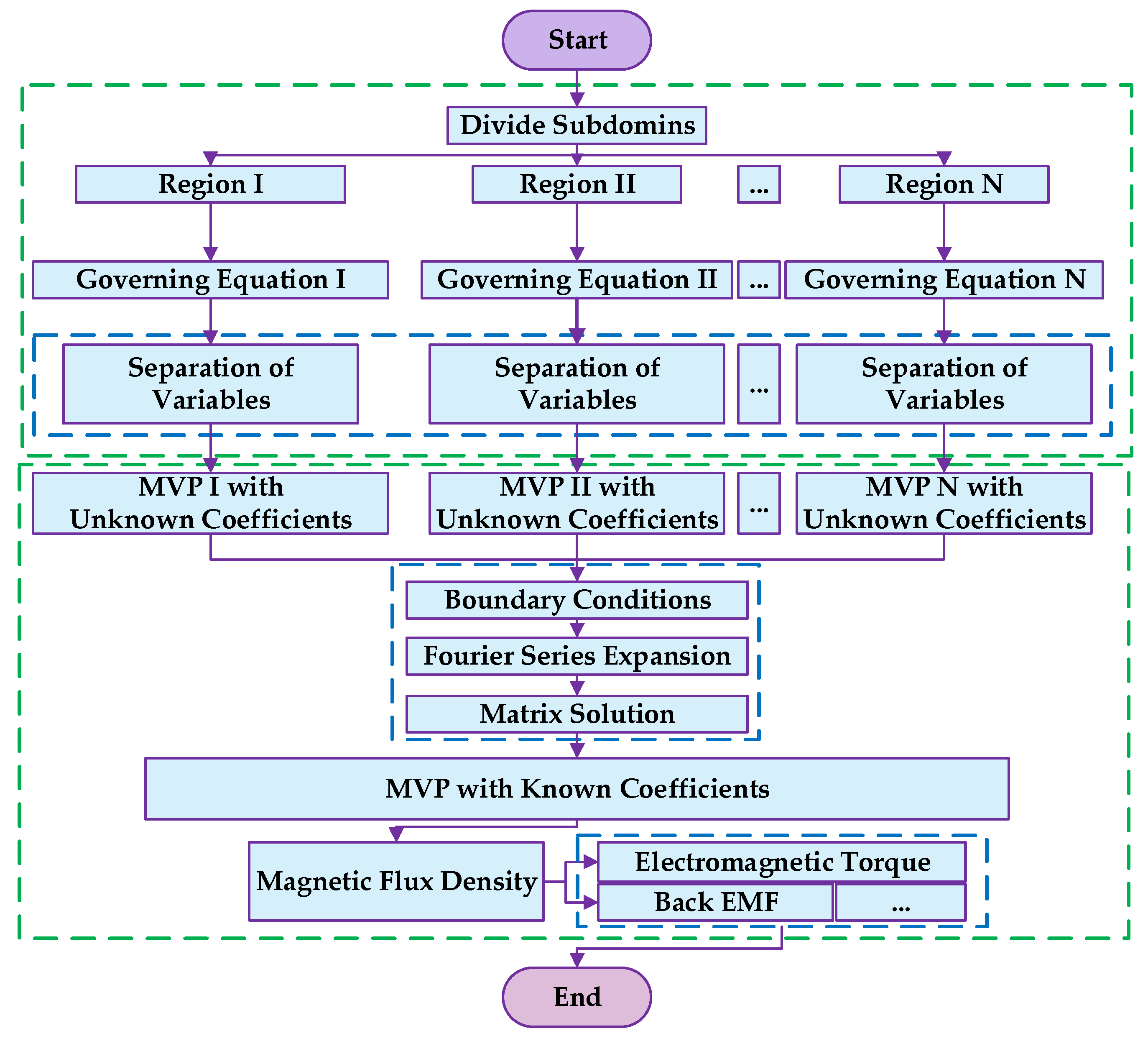
There are three kinds of boundary conditions within the DSSTVM, namely periodic condition, continuous condition, and Neumann condition [18]: In the air gap region, MVP has a period of 2π; at the interfaces between two regions, MVP A Z should be continuous; while the tangential component of the magnetic field intensity H should be continuous. Considering that the permeability of iron cores is regarded as infinite, the tangential component of H should be zero at the interface between the iron core and the region with other materials. With the above continuity rules, the boundary conditions of the DSSTVM will be determined from the innermost region to the outermost one subsequently. The flow chart of the analytical modeling process in this article is as shown in Figure 2.

3.1.1. Region I

First, the three sides surrounding the ith slot within Region I are connected to the iron core, where the tangential component of the magnetic field is zero. These features lead to:
A I , i r r = R 1 = 0 ; θ [ θ i , θ i + α ] A I , i θ θ i = 0 & A I , i θ θ i + α = 0 ;   r [ R 1 , R 2 ]
where A I , i is the MVP of the ith slot in Region I, θ i is the initial angle of the ith slot in Region I, and α is the angle of ith slot within Region I.
The remaining upper side of Region I is connected to both the iron core and Region II. For the arc that corresponds to the iron core, the tangential component of the magnetic field is zero, while for the arc that corresponds to Region II, the tangential component of the magnetic field is continuous between Region I and Region II, so we can obtain the following boundary condition:
A I , i r r = R 2 = A I I , j r r = R 2   θ [ θ j , θ j + β 1 ]   0   e l s e w h e r e     with   i = j
Considering the boundary conditions in (6) and (7), the general solution of the MVP and the corresponding Fourier series coefficient in Region I can be expressed as:
A I , i ( r , θ ) = A 0 i + 1 2 μ 0 J i 0 ( R 1 2 ln r 1 2 r 2 ) + n 1 = 1 A n 1 i α R 2 n 1 π P n 1 π / α ( r , R 1 ) E n 1 π / α ( R 2 , R 1 ) cos n 1 π α ( θ θ i ) + n 1 = 1 2 α n 1 π R 1 2 P n 1 π / α ( r , R 2 ) R 2 2 P n 1 π / α ( r , R 1 ) E n 1 π / α ( R 2 , R 1 ) + r 2 μ 0 J i n n 1 π / α 2 4 cos n 1 π α ( θ θ i )
where
A n 1 i = 2 α θ j θ j + β 1 A I I , j r r = R 2 cos n 1 π α ( θ θ i ) d θ

3.1.2. Region II

Secondly, for the jth slot of Region II, its two lateral sides are connected to the iron core, while the lower and upper sides are connected to the ith slot of Region I and IV, respectively. Thus, the boundary conditions can be deduced as:
A I I , j θ θ j = 0   ;     A I I , j θ θ j + β 1 = 0   with   r [ R 2 , R 4 ]
A I I , j ( R 2 , θ ) = A I , i ( R 2 , θ ) θ [ θ j , θ j + β 1 ] ; A I I , j ( R 4 , θ ) = A I V ( R 4 , θ ) θ [ θ j , θ j + β 1 ]
where A I I , j is the MVP of the jth slot within Region II, θ j is the initial angle of the jth slot within Region II, and β 1 is the angle of jth slot within Region II (slot-opening type 1).
Combining the boundary conditions in (10) and (11), the general solution of MVP and the corresponding Fourier series coefficient in Region II can be given by:
A I I , j ( r , θ ) = A 0 j + B 0 j ln r + n 2 = 1 A n 2 j E n 2 π / β 1 ( r , R 4 ) E n 2 π / β 1 ( R 2 , R 4 ) B n 2 j E n 2 π / β 1 ( r , R 2 ) E n 2 π / β 1 ( R 2 , R 4 ) cos n 2 π β 1 ( θ θ j )
where
A 0 j + B 0 j ln R 2 = 1 β 1 θ i + α β 1 2 θ i + α + β 1 2 A I , i ( R 2 , θ ) d θ
A 0 j + B 0 j ln R 4 = 1 β 1 θ i + α β 1 2 θ i + α + β 1 2 A I V ( R 4 , θ ) d θ
A n 2 j = 2 β 1 θ j θ j + β 1 A I , i ( R 2 , θ ) cos ( n 2 π β 1 ( θ θ j ) ) d θ
B n 2 j = 2 β 1 θ j θ j + β 1 A I V ( R 4 , θ ) cos ( n 2 π β 1 ( θ θ j ) ) d θ

3.1.3. Region III

Next, for the kth slot belonging to Region III, its three sides are connected to the iron core, where the tangential component of the magnetic field should be zero. The remaining upper side is connected to Region IV, so the MVPs of Regions III and IV are continuous at the upper side. Hence, the boundary conditions can be represented as:
A I I I , k θ θ k = 0 A I I I , k θ θ k + β 2 = 0 , r [ R 3 , R 4 ]   ; A I I I , k r r = R 3 = 0 θ [ θ k , θ k + β 2 ]
A I I I , k ( R 4 , θ ) = A I V ( R 4 , θ )   with   θ [ θ k , θ k + β 2 ]
where A I I I , k is the MVP of the kth slot within Region III, θ k is the initial angle of the kth slot within Region III, β 2 is the angle of kth slot within Region III (slot-opening type 2).
Taking into account boundary conditions (17) and (18), the general solution of MVP and the corresponding Fourier series coefficient in Region III can be acquired as:
A I I I , k ( r , θ ) = A 0 k + n 3 = 1 A n 3 k P n 3 π / β 2 ( r , R 4 ) P n 3 π / β 2 ( R 3 , R 4 ) cos n 3 π β 2 ( θ θ k )
where
A n 3 k = 2 β θ k θ k + β 2 A I V ( R 4 , θ ) cos ( n 3 π β 2 ( θ θ k ) ) d θ

3.1.4. Region IV

Then, the boundary conditions for Region IV are more complicated since Region IV is adjacent to Regions II, III, and V and the iron core. We use the continuity of the tangential component of the magnetic field and handle the boundary condition by introducing a piecewise function as follows:
A I V r r = R 4 = f 1 ( θ ) = A I I , j r r = R 4   θ [ θ j , θ j + β 1 ] A I I I , k r r = R 4 θ [ θ k , θ k + β 2 ] 0         e l s e w h e r e
A I V r r = R 5 = f 2 ( θ ) = A V , l r r = R 5 + μ 0 M θ , l θ [ θ l , θ l + γ ]   0             e l s e w h e r e  
where A I V is the MVP within Region IV, M θ , l is the tangential magnetization of the lth PM within Region V, θ l is the initial angle of the lth PM within Region V, and γ is the angle of the lth PM within Region V.
We take the boundary conditions in (21) and (22) into consideration, so the general solution of MVP and the corresponding Fourier series coefficient in Region IV can be written as:
A I V ( r , θ ) = A 0 I V + n 4 = 1 A n 4 I V R 4 n 4 P n 4 ( r , R 5 ) E n 4 ( R 4 , R 5 ) + B n 4 I V R 5 n 4 P n 4 ( r , R 4 ) E n 4 ( R 5 , R 4 ) cos ( n θ ) + n 4 = 1 C n 4 I V R 4 n 4 P n 4 ( r , R 5 ) E n 4 ( R 4 , R 5 ) + D n 4 I V R 5 n 4 P n 4 ( r , R 4 ) E n 4 ( R 5 , R 4 ) sin ( n θ )
where
A n 4 I V = 1 π 0 2 π f 1 ( θ ) cos ( n 4 θ ) d θ   ;     C n 4 I V = 1 π 0 2 π f 1 ( θ ) sin ( n 4 θ ) d θ
B n 4 I V = 1 π 0 2 π f 2 ( θ ) cos ( n 4 θ ) d θ   ;     D n 4 I V = 1 π 0 2 π f 2 ( θ ) sin ( n 4 θ ) d θ

3.1.5. Region V

Subsequently, for the lth slot in Region V, its two lateral sides are adjacent to the iron core, and the lower and upper sides are adjacent to Region IV and Region VI, respectively. Hence, its boundary conditions can be written as follows:
A V , l θ θ = θ l = 0   ;    A V , l θ θ = θ l + γ = 0   with   r [ R 5 , R 6 ]
A V , l ( R 5 , θ ) = A I V ( R 5 , θ ) θ [ θ l , θ l + γ ] ; A V , l ( R 6 , θ ) = A V I ( R 6 , θ ) θ [ θ l , θ l + γ ]
where A V , l is the MVP of the lth PM within Region V and θ l is the initial angle of lth PM within Region V.
Combing the boundary conditions in (26) and (27), the general solution of the MVP and the corresponding Fourier series coefficient in Region V can be obtained as:
A V , l ( r , θ ) = A 0 l + B 0 l ln r μ 0 M θ , l r + n 5 = 1 A n 5 l E n 5 π / γ ( r , R 6 ) E n 5 π / γ ( R 5 , R 6 ) B n 5 l E n 5 π / γ ( r , R 5 ) E n 5 π / γ ( R 5 , R 6 ) cos n 5 π γ ( θ θ l )
where
A 0 l + B 0 l ln R 5 = 1 γ θ l θ l + γ A I V ( R 5 , θ ) d θ
A 0 l + B 0 l ln R 6 = 1 γ θ l θ l + γ A V I ( R 6 , θ ) d θ
A n 5 l = 2 γ θ l θ l + γ A I V ( R 5 , θ ) cos n 5 π γ ( θ θ l ) d θ
B n 5 l = 2 γ θ l θ l + γ A V I ( R 6 , θ ) cos n 5 π γ ( θ θ l ) d θ

3.1.6. Region VI

Similar to the boundary conditions in Region IV, Region VI is adjacent to Region V and VII. We can write the boundary conditions for Region VI using the piecewise function as follows:
A V I r r = R 6 = g 1 ( θ ) = A V , l r r = R 6 + μ 0 M θ , l θ [ θ l , θ l + γ ] 0     e l s e w h e r e
A V I r r = R 7 = g 2 ( θ ) = A V I I , m r r = R 7 θ [ θ m , θ m + δ ] 0     e l s e w h e r e  
where A V I is the MVP within Region VI, A V I I , m is the MVP of the mth slot within Region VII, θ m is the initial angle of mth slot within Region VII and δ is the angle of mth slot within Region VII.
Taking into account the boundary conditions (33) and (34), the general solution of MVP and the corresponding Fourier series coefficient in Region VI can be calculated as:
A V I ( r , θ ) = A 0 V I + n 6 = 1 A n 6 V I R 6 n 6 P n 6 ( r , R 7 ) E n 6 ( R 4 , R 5 ) + B n 6 V I R 7 n 6 P n 6 ( r , R 6 ) E n 6 ( R 7 , R 6 ) cos ( n θ ) + n 6 = 1 C n 6 V I R 6 n 6 P n 6 ( r , R 7 ) E n 6 ( R 4 , R 5 ) + D n 6 V I R 7 n 6 P n 6 ( r , R 6 ) E n 6 ( R 7 , R 6 ) sin ( n θ )
where
A n 6 V I = 1 π 0 2 π g 1 ( θ ) cos ( n 6 θ ) d θ   ;         C n 6 V I = 1 π 0 2 π g 1 ( θ ) sin ( n 6 θ ) d θ  
B n 6 V I = 1 π 0 2 π g 2 ( θ ) cos ( n 6 θ ) d θ   ;      D n 6 V I = 1 π 0 2 π g 2 ( θ ) sin ( n 6 θ ) d θ

3.1.7. Region VII

Finally, the three sides of the mth slot within Region VII are connected to the iron core, and the remaining lower side is adjacent to Region VI. Therefore, the corresponding boundary conditions can be arranged as:
A V I I , m θ θ m = 0 A V I I , m θ θ m + δ = 0 ,   r [ R 7 , R 8 ]   ; A V I I , m r r = R 8 = 0 θ [ θ m , θ m + δ ]
where
A V I I , m ( R 7 , θ ) = A V I ( R 7 , θ )   with   θ [ θ m , θ m + δ ]
Considering the boundary conditions (38) and (39) together, the general solution of MVP and the corresponding Fourier series coefficient in Region VI can be written as:
A V I I , m ( r , θ ) = A 0 m + 1 2 μ 0 J m R 8 2 ln r 1 2 r 2 + n 7 = 1 A n 7 m P n 7 π / δ ( r , R 8 ) P n 7 π / δ ( R 7 , R 8 ) cos n 7 π δ ( θ θ m )
where
A n 7 m = 2 δ θ m θ m + δ A V I ( R 7 , θ ) cos n 7 π δ ( θ θ m ) d θ
The unknown Fourier series coefficients in the MVP expression and the unknown integral functions are deduced in detail in Appendix B and Appendix C, respectively. Ultimately, by combining all the Fourier series coefficient expressions of MVPs within the machine domain, we can obtain a system of linear equations with a unique solution. The Fourier series coefficients can be obtained by solving the system of linear equations in a numerical computing software, for instance, MATLAB R2022b. Subsequently, the magnetic flux density B in all these regions can be acquired according to:
B r = 1 r A z θ   and   B θ = A z r  
where B r and B θ are the radial and tangential components of magnetic flux density, respectively.

3.2. Postprocessing Electromagnetic Parameters Calculation

The output torque on the rotor of DSSTVM T r should be the sum of electromagnetic torques on the inner air gap and outer air gap, namely T i n n e r _ g a p and T o u t e r _ g a p . Then, the electromagnetic torque on the air gap can be calculated by using the Maxwell stress tensor, which can be given as follows:
T i n n e r _ g a p = L R i n 2 μ 0 0 2 π B I V , r ( R i n , θ ) B I V , θ ( R i n , θ ) d θ
T o u t e r _ g a p = L R o u t 2 μ 0 0 2 π B V I , r ( R o u t , θ ) B V I , θ ( R o u t , θ ) d θ
T r = T i n n e r _ g a p + T o u t e r _ g a p
where R i n and R o u t are the radii in the middle of the inner air gap and outer air gap.
As for the flux linkage of each coil, it can be calculated as the area integral of MVP within the slot region. Then, the phase flux can be obtained as the product of the slot-connecting matrix and the flux linkage vector. The back electromotive force (EMF) can be acquired as the derivative of the phase flux with respect to time. The detailed deduction process can be referred to [19].

4. Finite Element Analysis Validation

The DSSTVM simulation model is constructed via FEA to verify the effectiveness of the proposed SDM, and the structural parameters of the DSSTVM model are referred to in Table 1. The DSSTVM’s main performance indicators are average electromagnetic torque, electromagnetic torque ripple rate, efficiency, loss, etc. The above indicators will determine the DSSTVM’s output performance under different operating conditions and application scenarios. In the aspect of magnetic flux density distribution, the analytical model would provide detailed insights into how the magnetic flux density is distributed across the machine. This helps to identify areas of high flux density, potential magnetic flux leakage, and regions where saturation might occur. According to Maxwell stress tensor method in (43) and (44), the magnetic flux density distribution in the airgap is essential for the calculation of electromagnetic torque. Understanding the magnetic flux distribution is crucial for optimizing the design to maximize the efficiency and torque capability of the machine, as well as for reducing torque ripple and ensuring smooth operation. In this article, to evaluate the accuracy of the proposed method, the calculation results based on the proposed method are compared with FEA.
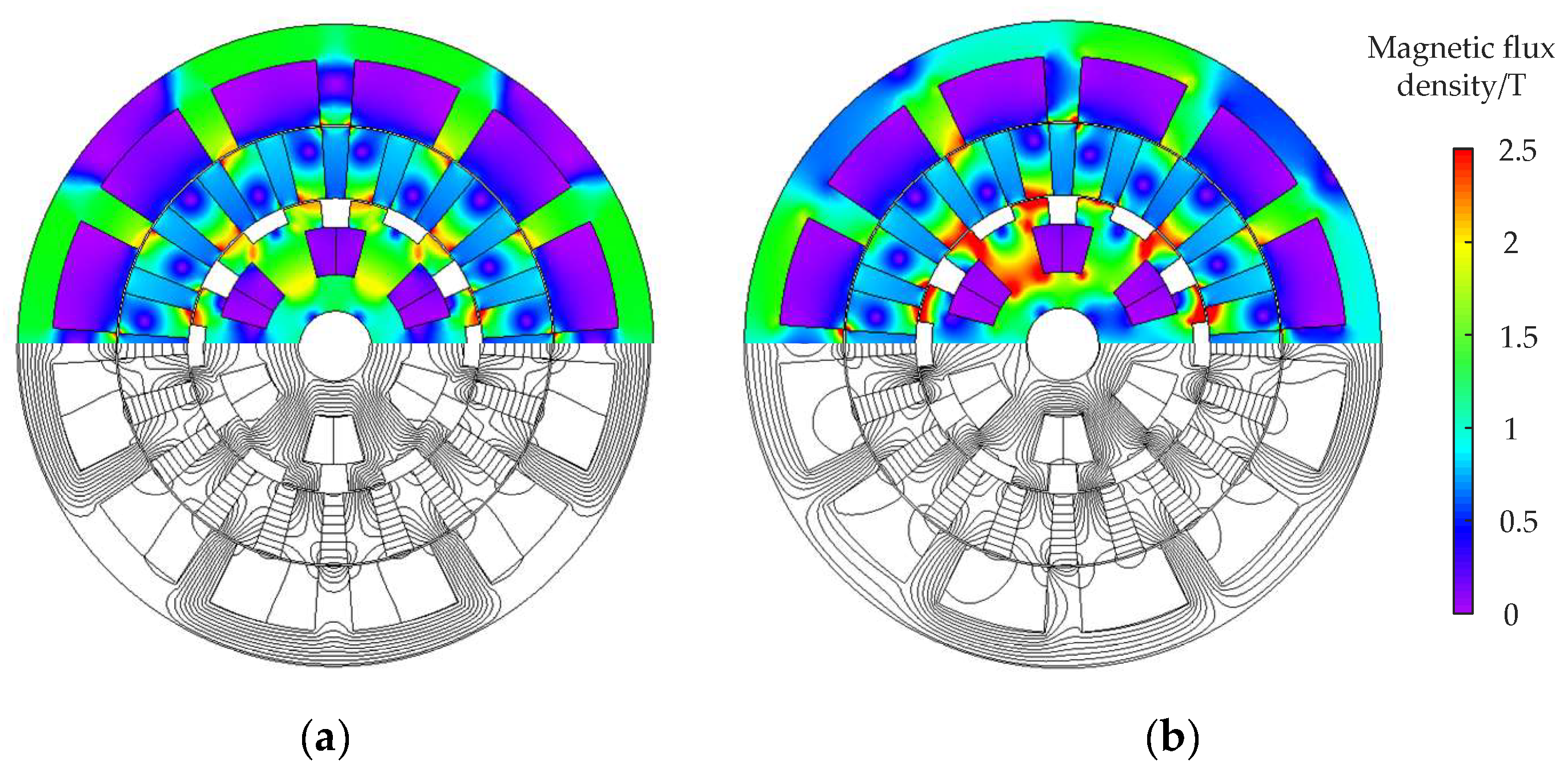
The no-load and on-load magnetic flux density and flux line distributions calculated by FEA are depicted in Figure 3a and Figure 3b, respectively. The no-load magnetic flux density distribution comparison between SDM and FEA in the inner and outer air gaps are illustrated in Figure 4a and Figure 4b, respectively. The harmonic spectrum of the air gap magnetic flux density in the middle of the inner air gap and outer air gap under no-load condition between SDM and FEA are illustrated in Figure 5a and Figure 5b, respectively. The rated load magnetic flux density distribution comparison between SDM and FEA in the inner and outer air gaps are illustrated in Figure 6a and Figure 6b, respectively. The harmonic spectrum of the air gap magnetic flux density in the middle of the inner air gap and outer air gap under rated load condition between SDM and FEA are illustrated in Figure 7a and Figure 7b, respectively. It can be observed that the proposed SDM has good agreement with that of FEA in terms of the magnetic flux densities and harmonic spectrum in inner and outer air gaps.
One prominent advantage of using DSSTVM is the reduction in flux leakage, so the output torque and power factor of the machines can be greatly improved. To minimize the flux leakage of the spoke-type PMs on the rotor, one can determine the optimal shift angle between the inner and outer stators via the parameter-sweeping method, as depicted in Figure 1. This can also be achieved by using the proposed SDM, and Figure 8a illustrates the variation in the output torque and power factor with the variation in shift angle from 0 to 30 degrees, calculated by both SDM and FEA.
No-load back EMF is one essential parameter in motor design, it is influenced by the motor’s topology, the PM arrangement, etc. No-load back EMF can impact the control strategy in motor the operation. Understanding its waveform helps in designing appropriate topologies and control algorithms to achieve optimal performance. In addition, torque is another critical performance indicator for DSSTVM. The analytical model would provide the torque characteristics of the DSSTVM, including the average torque, torque ripple, and the relationship between torque and current. It helps to understand the impact of design parameters on average torque and torque ripple. Therefore, analyzing the output torque helps in optimizing the motor design for desired load conditions and ensuring that the motor generates the necessary performance for its intended application.
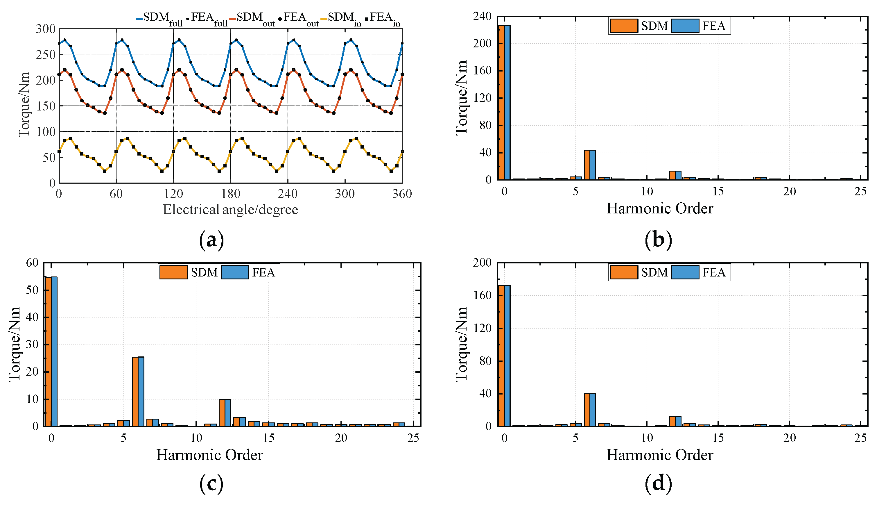
Therefore, the DSSTVM’s no-load back EMF waveforms with different sets of windings operating can be obtained by using FEA and SDM, as can be seen in Figure 8b. The harmonic spectrum of the no-load back EMF waveforms in the inner stator and outer stator between SDM and FEA are illustrated in Figure 9a and Figure 9b, respectively. The DSSTVM’s output torques with different sets of windings operating can be obtained by using FEA and SDM, as can be seen in Figure 10a. The rated load torque harmonic spectrum of the DSSTVM in mode 1 (the inner and outer parts of DSSTVM operate simultaneously to generate the torque), mode 2 (the inner part of DSSTVM operates to generate the torque), and mode 3 (the outer part of DSSTVM operate to generate the torque) between SDM and FEA are illustrated in Figure 10b, Figure 10c and Figure 10d, respectively.
In terms of the amplitude of the radial and tangential magnetic flux density in the middle of the inner air gap and outer air gap, compared with the permanent magnet synchronous motors (PMSMs), DSSTVM has a higher magnetic flux density because of the magnetic field modulation. As a result, according to the Maxwell stress tensor, the higher magnetic flux density in the airgap generates higher electromagnetic torque. Therefore, in terms of the rated load torque, in one aspect, because of the amplitude of the radial and tangential magnetic flux density in the middle of the inner air gap and outer air gap, compared with the PMSMs, DSSTVM has a higher electromagnetic torque. In another aspect, the double-stator characteristic makes the DSSTVM able to generate the electromagnetic torque from the inner and outer airgap simultaneously or separately, which makes the DSSTVM have higher electromagnetic torque density and wider application scenarios.
However, a slight deviation between the two approaches can be observed, where the values of SDM are smaller. This is due to the maximum harmonic limit of the SDM, and the error can be smaller if the calculated maximum harmonic number increases. However, the computation time increases along with the rise in the calculated maximum harmonic number, so we should make a trade-off for different application scenarios. As for the computation time, it takes the SDM 29 s for a single step, while it takes FEA 47 s. Thus, the computation time of SDM is only 62% of that of FEA, proving that the SDM is prior to being applied to the initial design stage to determine the slot-pole combinations and parameters’ ranges to be optimized for DSSTVM as well as other double-stator machines.

5. Conclusions

This paper presents a high-fidelity analytical method, namely the subdomain method, for calculating the magnetic field distribution and the related electromagnetic parameters in DSSTVM. The magnetic flux density distribution, back EMF, and output torque of the DSSTVM are computed by both the SDM and FEA. Compared to FEA, the proposed SDM can save computation time while maintaining accuracy. The deduction process completes the SDM for double-stator machines with various structures as well as slot-pole combinations. This analytical method can be applied for topology investigation and optimization for double-stator machines.

Author Contributions

Conceptualization, X.S.; methodology, X.S.; software, H.Z.; validation, H.Z.; formal analysis, J.Y.; investigation, J.Y.; resources, X.S.; data curation, H.Z.; writing—original draft preparation, X.S.; writing—review and editing, C.L.; visualization, Z.O.; supervision, H.Z.; project administration, H.Z.; funding acquisition, H.Z. All authors have read and agreed to the published version of the manuscript.

Funding

This work was supported in part by the Guangdong Basic and Applied Basic Research Foundation under Project 2022A1515110361 and Guangzhou Science and Technology Bureau under Project SL2022A04J00605 and Project SL2022A03J00086.

Institutional Review Board Statement

Not applicable.

Informed Consent Statement

Not applicable.

Data Availability Statement

Data are contained within the article.

Conflicts of Interest

The authors declare no conflicts of interest.

Abbreviations

R1The inner radius of the inner stator slot
R2Inner radius of opening slot type 1
R3Inner radius of opening slot type 2
R4The outer radius of the inner stator
R5The inner radius of the rotor
R6The outer radius of the rotor
R7The inner radius of the outer stator
R8The inner radius of the outer stator yoke
NTurns number
LStack length
αThe angle of the ith slot within Region I
β1The angle of the jth slot within Region II (slot-opening type 1)
β2The angle of the kth slot in Region III (slot-opening type 2)
γThe angle of the lth PM within Region V
δThe angle of the mth slot within Region VII
PrPole-pair number of rotor’s permanent magnets (PMs)
PwPole-pair numbers of the inner and outer stators’ windings
ZSlot numbers of the inner and outer stators
JzCurrent density
A I , i MVP of the ith slot in Region I
A I I , j MVP of the jth slot within Region II
A I I I , k MVP of the kth slot within Region III
A I V MVP within Region IV
A V , l MVP of the lth slot within Region V
A V I MVP within Region VI
A V I I , m MVP of the mth slot within Region VII
θ i The initial angle of the ith slot in Region I
θ j The initial angle of the jth slot within Region II
θ k The initial angle of the kth slot within Region III
M θ , l Tangential magnetization of the lth PM within Region V
θ l The initial angle of the lth PM within Region V
θ m The initial angle of the mth slot within Region VII

Appendix A

By applying the method of separation of variables, the complementary solution to (2) is deducted as follows. Considering various materials’ properties, the magnetic vector potential (MVP) A z in the polar coordinates is:
A z r 2 + 1 r A z r + 1 r 2 A z θ 2 = μ 0 r ( ( r M θ ) r M r θ ) μ 0 J z
The homogeneous form of (A1) is Laplace’s equation:
A z r 2 + 1 r A z r + 1 r 2 A z θ 2 = 0
After the separation of variables, A z ( r , θ ) can be written as:
A z ( r , θ ) = R ( r ) Θ ( θ )
After bringing (A3) back into (A2):
r R ( r ) ( r d 2 R ( r ) d r 2 + d R ( r ) d r ) = 1 Θ ( θ ) d 2 Θ ( θ ) d θ 2 = λ
According to the ordinary differential equation theory, when λ = 0 , the solution of R ( r ) and Θ ( θ ) in (A4) are as follows:
R ( r ) = A 0 + B 0 ln r ,   Θ ( θ ) = C 0 θ + D 0
When λ = n 2 ( n is the positive integer), the solutions of R ( r ) and Θ ( θ ) in (A4) are as follows:
R ( r ) = A n r n + B n r n ,   Θ ( θ ) = C n cos n θ + D n sin n θ
When λ = n 2 ( n is the positive integer), the solutions of R ( r ) and Θ ( θ ) in (A4) are as follows:
R ( r ) = E n sin ( n ln r ) + F n cos ( n ln r ) ,   Θ ( θ ) = G n e n θ + H n e n θ
Considering λ = 0 , λ = n 2 and λ = n 2 , as well as n with different values, the complementary solution to (A1) can be written as:
A z ( r , θ ) = ( A 0 + B 0 ln r ) ( C 0 θ + D 0 ) + n = 1 A n r n + B n r n C n cos n θ + D n sin n θ + n = 1 [ E n sin ( n ln r ) + F n cos ( n ln r ) ] ( G n e n θ + H n e n θ )
Considering the periodic boundary condition A z ( r , θ ) θ = 0 = A z ( r , θ ) θ = 2 π for r , we obtain C 0 = 0 , G n = 0 and H n = 0 . After merging ( A 0 + B 0 ln r ) D 0 as A 0 + B 0 ln r , (A8) can be simplified as:
A z ( r , θ ) = ( A 0 + B 0 ln r ) + n = 1 A n r n + B n r n C n cos n θ + D n sin n θ
Considering A z ( r , θ ) is finite when r = 0 , we then obtain B 0 = 0 . Therefore, (A9) can be further simplified as:
A z ( r , θ ) = A 0 + n = 1 A n r n + B n r n C n cos n θ + D n sin n θ
Taking Region VI as an example, in Region VI, magnetic vector potential (MVP) is:
A V I ( r , θ ) = A 0 V I + n = 1 ( A n 6 V I r n 6 + B n 6 V I r n 6 ) ( C n 6 V I cos n 6 θ + D n 6 V I sin n 6 θ )
Then we can rewrite the form of A V I ( r , θ ) with the values of A n 6 V I , B n 6 V I , C n 6 V I and D n 6 V I change (as A n 6 V I , B n 6 V I , C n 6 V I and D n 6 V I are the unknown coefficients so they can be redetermined after the expression of A V I ( r , θ ) changes and the value of A V I ( r , θ ) keep unchanged):
A V I ( r , θ ) = A 0 V I + n 6 = 1 A n 6 V I r n 6 + B n 6 V I r n 6 cos ( n 6 θ ) + n 6 = 1 C n 6 V I r n 6 + D n 6 V I r n 6 sin ( n 6 θ )
Alternatively, the following form:
A V I ( r , θ ) = A 0 V I + n 6 = 1 A n 6 V I r R 7 n 6 + B n 6 V I r R 6 n 6 cos ( n 6 θ ) + n 6 = 1 C n 6 V I r R 7 n 6 + D n 6 V I r R 6 n 6 sin ( n 6 θ )
After the mathematical deduction, we obtain the following equations (notice that A n 6 V I , B n 6 V I , C n 6 V I and D n 6 V I change after the deduction; however, they are the unknown coefficients so we can solve them with the proper value while A V I ( r , θ ) keeping unchanged:
A V I ( r , θ ) = A 0 V I + n 6 = 1 A n 6 V I R 6 n 6 1 R 7 n 6 B n 6 V I R 7 n 6 1 R 6 n 6 R 6 R 7 n 6 R 7 R 6 n 6 r n 6 + A n 6 V I R 6 n 6 R 7 1 n 6 B n 6 V I R 7 n 6 R 6 1 n 6 R 6 R 7 n 6 R 7 R 6 n 6 r n 6 cos ( n 6 θ ) + n 6 = 1 C n 6 V I R 6 n 6 1 R 7 n 6 D n 6 V I R 7 n 6 1 R 6 n 6 R 6 R 7 n 6 R 7 R 6 n 6 r n 6 + C n 6 V I R 6 n 6 R 7 1 n 6 D n 6 V I R 7 n 6 R 6 1 n 6 R 6 R 7 n 6 R 7 R 6 n 6 r n 6 sin ( n 6 θ )
Therefore, we get:
A V I ( r , θ ) = A 0 V I + n 6 = 1 A n 6 V I R 6 n 6 1 R 7 n 6 r n 6 R 6 R 7 n 6 R 7 R 6 n 6 B n 6 V I R 7 n 6 1 R 6 n 6 r n 6 R 6 R 7 n 6 R 7 R 6 n 6 + A n 6 V I R 6 n 6 R 7 n 6 r n 6 R 6 R 7 n 6 R 7 R 6 n 6 B n 6 V I R 7 n 6 R 6 n 6 r n 6 R 6 R 7 n 6 R 7 R 6 n 6 cos ( n 6 θ ) + n 6 = 1 C n 6 V I R 6 n 6 1 R 7 n 6 r n 6 R 6 R 7 n 6 R 7 R 6 n 6 D n 6 V I R 7 n 6 1 R 6 n 6 r n 6 R 6 R 7 n 6 R 7 R 6 n 6 + C n 6 V I R 6 n 6 R 7 n 6 r n 6 R 6 R 7 n 6 R 7 R 6 n 6 D n 6 V I R 7 n 6 R 6 n 6 r n 6 R 6 R 7 n 6 R 7 R 6 n 6 sin ( n 6 θ )
Consequently,
A V I ( r , θ ) = A 0 V I + n 6 = 1 A n 6 V I R 6 n 6 r R 7 n 6 R 6 R 7 n 6 R 7 R 6 n 6 + A n 6 V I R 6 n 6 R 7 r n 6 R 6 R 7 n 6 R 7 R 6 n 6 B n 6 V I R 7 n 6 r R 6 n 6 R 6 R 7 n 6 R 7 R 6 n 6 B n 6 V I R 7 n 6 R 6 r n 6 R 6 R 7 n 6 R 7 R 6 n 6 cos ( n 6 θ ) + n 6 = 1 C n 6 V I R 6 n 6 r R 7 n 6 R 6 R 7 n 6 R 7 R 6 n 6 + C n 6 V I R 6 n 6 R 7 r n 6 R 6 R 7 n 6 R 7 R 6 n 6 D n 6 V I R 7 n 6 r R 6 n 6 R 6 R 7 n 6 R 7 R 6 n 6 D n 6 V I R 7 n 6 R 6 r n 6 R 6 R 7 n 6 R 7 R 6 n 6 sin ( n 6 θ )
After a similar terms’ combination, we get:
A V I ( r , θ ) = A 0 V I + n 6 = 1 A n 6 V I R 6 n 6 r R 7 n 6 + R 7 r n 6 R 6 R 7 n 6 R 7 R 6 n 6 + B n 6 V I R 7 n 6 r R 6 n 6 + R 6 r n 6 R 7 R 6 n 6 R 6 R 7 n 6 cos ( n 6 θ ) + n 6 = 1 C n 6 V I R 6 n 6 r R 7 n 6 + R 7 r n 6 R 6 R 7 n 6 R 7 R 6 n 6 + D n 6 V I R 7 n 6 r R 6 n 6 + R 6 r n 6 R 7 R 6 n 6 R 6 R 7 n 6 sin ( n 6 θ )
The relationship between P w u , v and E w u , v is listed for further simplification:
P w u , v = u v w + v u w , E w u , v = u v w v u w
P w u , v u = E w u , v , E w u , v u = P w u , v
Because of the relationship between P w u , v and E w u , v , it is easy to obtain the derivative in complicated expressions when the expression needs the derivative (when utilizing the boundary conditions), therefore, we obtain the form of A V I ( r , θ ) , containing P w u , v and E w u , v for simplification:
A V I ( r , θ ) = A 0 V I + n 6 = 1 A n 6 V I R 6 n 6 P n 6 ( r , R 7 ) E n 6 ( R 6 , R 7 ) + B n 6 V I R 7 n 6 P n 6 ( r , R 6 ) E n 6 ( R 7 , R 6 ) cos ( n 6 θ ) + n 6 = 1 C n 6 V I R 6 n 6 P n 6 ( r , R 7 ) E n 6 ( R 6 , R 7 ) + D n 6 V I R 7 n 6 P n 6 ( r , R 6 ) E n 6 ( R 7 , R 6 ) sin ( n 6 θ )
After utilizing boundary conditions (33) and (34), we get:
A V I r r = R 6 = n 6 = 1 A n 6 V I R 6 n 6 E n 6 ( R 6 , R 7 ) E n 6 ( R 6 , R 7 ) + B n 6 V I R 7 n 6 E n 6 ( R 6 , R 6 ) E n 6 ( R 7 , R 6 ) cos ( n 6 θ ) + n 6 = 1 C n 6 V I R 6 n 6 E n 6 ( R 6 , R 7 ) E n 6 ( R 6 , R 7 ) + D n 6 V I R 7 n 6 E n 6 ( R 6 , R 6 ) E n 6 ( R 7 , R 6 ) sin ( n 6 θ ) = g 1 ( θ )
According to:
P w u , u = u u w + u u w = 2
E w u , u = u u w u u w = 0
E n 6 ( R 6 , R 7 ) E n 6 ( R 6 , R 7 ) = 1 , E n 6 ( R 6 , R 6 ) = 0
Therefore, we get:
A V I r r = R 6 = n 6 = 1 A n 6 V I R 6 n 6 cos ( n 6 θ ) + n 6 = 1 C n 6 V I R 6 n 6 sin ( n 6 θ ) = g 1 ( θ )
Similarly, according to:
E n 6 ( R 7 , R 6 ) E n 6 ( R 7 , R 6 ) = 1 , E n 6 ( R 7 , R 7 ) = 0
Then we get:
A V I r r = R 7 = n 6 = 1 B n 6 V I R 7 n 6 cos ( n 6 θ ) + n 6 = 1 D n 6 V I R 7 n 6 sin ( n 6 θ ) = g 2 ( θ )
According to a generalized Fourier series expansion of (A25) and (A27), we obtain the following equations:
A n 6 V I = 1 π 0 2 π A V I r r = R 6 cos ( n 6 θ ) d θ   ;         C n 6 V I = 1 π 0 2 π A V I r r = R 6 sin ( n 6 θ ) d θ  
B n 6 V I = 1 π 0 2 π A V I r r = R 7 cos ( n 6 θ ) d θ   ;         D n 6 V I = 1 π 0 2 π A V I r r = R 7 sin ( n 6 θ ) d θ
Finally, after simplification, we obtain the following equations:
A n 6 V I = 1 π 0 2 π g 1 ( θ ) cos ( n 6 θ ) d θ   ;   C n 6 V I = 1 π 0 2 π g 1 ( θ ) sin ( n 6 θ ) d θ  
B n 6 V I = 1 π 0 2 π g 2 ( θ ) cos ( n 6 θ ) d θ   ;   D n 6 V I = 1 π 0 2 π g 2 ( θ ) sin ( n 6 θ ) d θ

Appendix B

The unknown Fourier series coefficients in the MVP expression of each subdomain need to be deduced and calculated for consequent Fourier series coefficient matrices solution. The detailed Fourier series coefficients in the MVP expression of each subdomain can be calculated via the Fourier expansion in each subdomain boundary and applying the adjacent subdomain MVP values or derivative information. Therefore, the detailed Fourier series coefficients in each subdomain of DSVMs can be calculated as follows.
First of all, according to the definition of (4) and (5), the relationship between P w u , v and E w u , v is described as follows for later clarity and simplicity in the partial derivation:
P w u , v u = E w u , v
E w u , v u = P w u , v
In Region I, considering the boundary condition of Region I and Region II, after substituting (12) into (9), we get:
A n 1 i = 4 B 0 j n 1 π R 2 sin ( n 1 π β 1 2 α ) cos ( n 1 π 2 ) + n 2 = 1 ( A n 2 j P n 2 π / β 1 ( R 2 , R 4 ) E n 2 π / β 1 ( R 2 , R 4 ) B n 2 j 2 E n 2 π / β 1 ( R 2 , R 4 ) ) 2 n 2 π α β 1 R 2 F ( n 1 , n 2 )
In Region II, considering the boundary condition of Region I and Region II, after substituting (8) into (15), considering the boundary condition of Region II and Region IV, after substituting (23) into (16), we get:
A n 2 j = n 1 = 1 ( A n 1 i 2 α R 2 n 1 π β 1 P n 1 π / α ( R 2 , R 1 ) E n 1 π / α ( R 2 , R 1 ) 2 μ 0 J i n β 1 n 1 π / α 2 4 ( 2 α n 1 π R 1 2 2 R 2 2 P n 1 π / α ( R 2 , R 1 ) E n 1 π / α ( R 2 , R 1 ) + R 2 2 ) F ( n 1 , n 2 )
B n 2 j = n 4 = 1 ( A n 4 I V 2 R 4 n 4 β 1 P n 4 ( R 4 , R 5 ) E n 4 ( R 4 , R 5 ) + B n 4 I V 2 R 5 n 4 β 1 2 E n 4 ( R 5 , R 4 ) ) f a ( n 2 , n 4 , j ) + n 4 = 1 ( C n 4 I V 2 R 4 n 4 β 1 P n 4 ( R 4 , R 5 ) E n 4 ( R 4 , R 5 ) + D n 4 I V 2 R 5 n 4 β 1 2 E n 4 ( R 5 , R 4 ) ) g a ( n 2 , n 4 , j )
In Region III, considering the boundary condition of Region III and Region IV, after substituting (23) into (20), we get:
A n 3 k = n 4 = 1 ( A n 4 I V 2 R 4 n 4 β 1 P n 4 ( R 4 , R 5 ) E n 4 ( R 4 , R 5 ) + B n I V 2 R 5 n 4 β 1 2 E n 4 ( R 5 , R 4 ) ) f t ( n 3 , n 4 , k ) + n 4 = 1 ( A n 4 I V 2 R 4 n 4 β 1 P n 4 ( R 4 , R 5 ) E n 4 ( R 4 , R 5 ) + B n I V 2 R 5 n 4 β 1 2 E n 4 ( R 5 , R 4 ) ) g t ( n 3 , n 4 , k )
In Region IV, considering the boundary condition of Region IV, Region II, and Region III, after substituting (12), (19) and (21) into (24), considering the boundary condition of Region IV and Region V, after substituting (22) and (28) into (25), we get:
A n 4 I V = j = 1 P i B 0 j π R 4 r j ( n 4 , j ) + j = 1 P i n 2 = 1 A n 2 j n 2 β 1 R 4 2 E n 2 π / β 1 ( R 2 , R 4 ) f a ( n 2 , n 4 , j ) j = 1 P i n 2 = 1 B n 2 j n 2 β 1 R 4 P n 2 π / β 1 ( R 4 , R 2 ) E n 2 π / β 1 ( R 2 , R 4 ) f a ( n 2 , n 4 , j ) + k = 1 P i n 3 = 1 A n 3 k n 3 β 2 R 4 E n 3 π / β 2 ( R 4 , R 3 ) P n 3 π / β 2 ( R 3 , R 4 ) f t ( n 3 , n 4 , k )
C n 4 I V = j = 1 P i B 0 j π R 4 s j ( n 4 , j ) + j = 1 P i n 2 = 1 A n 2 j n 2 β 1 R 4 2 E n 2 π / β 1 ( R 2 , R 4 ) g a ( n 2 , n 4 , j ) j = 1 P i n 2 = 1 B n 2 j n 2 β 1 R 4 P n 2 π / β 1 ( R 4 , R 2 ) E n 2 π / β 1 ( R 2 , R 4 ) g a ( n 2 , n 4 , j ) + k = 1 P i n 3 = 1 A n 3 k n 3 β 2 R 4 E n 3 π / β 2 ( R 4 , R 3 ) P n 3 π / β 2 ( R 3 , R 4 ) g t ( n 3 , n 4 , k )
B n 4 I V = l = 1 Q B 0 l π R 5 r f ( n 4 , l ) + l = 1 Q n 5 = 1 A n 5 l n 5 γ R 5 P n 5 π / γ ( R 5 , R 6 ) E n 5 π / γ ( R 5 , R 6 ) f f ( n 5 , n 4 , l ) l = 1 Q n 5 = 1 B n 5 l n 5 γ R 5 2 E n 5 π / γ ( R 5 , R 6 ) f f ( n 5 , n 4 , l )
D n 4 I V = l = 1 Q B 0 l π R 5 s f ( n 4 , l ) + l = 1 Q n 5 = 1 A n 5 l n 5 γ R 5 P n 5 π / γ ( R 5 , R 6 ) E n 5 π / γ ( R 5 , R 6 ) g f ( n 5 , n 4 , l ) l = 1 Q n 5 = 1 B n 5 l n 5 γ R 5 2 E n 5 π / γ ( R 5 , R 6 ) g f ( n 5 , n 4 , l )
In Region V, considering the boundary condition of Region V and Region IV, after substituting (23) into (29) and (31), considering the boundary condition of Region V and Region VI, after substituting (35) into (30) and (32), we get:
A n 5 l = n 4 = 1 ( A n 4 I V 2 R 4 n 4 γ 2 E n 4 ( R 4 , R 5 ) + B n 4 I V 2 R 5 n 4 γ P n 4 ( R 5 , R 4 ) E n 4 ( R 5 , R 4 ) ) f f ( n 5 , n 4 , l ) + n 4 = 1 ( C n 4 I V 2 R 4 n 4 γ 2 E n 4 ( R 4 , R 5 ) + D n 4 I V 2 R 5 n 4 γ P n 4 ( R 5 , R 4 ) E n 4 ( R 5 , R 4 ) ) g f ( n 5 , n 4 , l )
B n 5 l = n 6 = 1 ( A n 6 V I 2 R 6 n 6 γ P n 6 ( R 6 , R 7 ) E n 6 ( R 6 , R 7 ) + B n 6 V I 2 R 7 n 6 γ 2 E n 6 ( R 7 , R 6 ) ) f f ( n 5 , n 6 , l ) + n 6 = 1 ( C n 6 V I 2 R 6 n 6 γ P n 6 ( R 6 , R 7 ) E n 6 ( R 6 , R 7 ) + D n 6 V I 2 R 7 n 6 γ 2 E n 6 ( R 7 , R 6 ) ) g f ( n 5 , n 6 , l )
A 0 l + B 0 l ln R 5 μ 0 M θ , l R 5 = A 0 I V + n 4 = 1 ( A n 4 I V R 4 n 4 γ 2 E n 4 ( R 4 , R 5 ) + B n 4 I V R 5 n 4 γ P n 4 ( R 5 , R 4 ) E n 4 ( R 5 , R 4 ) ) r f ( n 4 , l ) + n 4 = 1 ( C n 4 I V R 4 n 4 γ 2 E n 4 ( R 4 , R 5 ) + D n 4 I V R 5 n 4 γ P n 4 ( R 5 , R 4 ) E n 4 ( R 5 , R 4 ) ) s f ( n 4 , l )
A 0 l + B 0 l ln R 6 μ 0 M θ , l R 6 = A 0 V I + n 6 = 1 ( A n 6 V I R 6 n 6 γ P n 6 ( R 6 , R 7 ) E n 6 ( R 6 , R 7 ) + B n 6 V I R 7 n 6 γ 2 E n 6 ( R 7 , R 6 ) ) r f ( n 6 , l ) + n 6 = 1 ( C n 6 V I R 6 n 6 γ P n 6 ( R 6 , R 7 ) E n 6 ( R 6 , R 7 ) + D n 6 V I R 7 n 6 γ 2 E n 6 ( R 7 , R 6 ) ) s f ( n 6 , l )
In Region VI, considering the boundary condition of Region VI and Region V, after substituting (28) and (33) into (36), considering the boundary condition of Region VI and Region VII, after substituting (34) and (40) into (37), we get:
A n 6 V I = l = 1 Q B 0 l π R 6 r f ( n 6 , l ) + l = 1 Q n 5 = 1 A n 5 l n 5 γ R 6 2 E n 5 π / γ ( R 5 , R 6 ) f f ( n 5 , n 6 , l ) l = 1 Q n 5 = 1 B n 5 l n 5 γ R 6 P n 5 π / γ ( R 6 , R 5 ) E n 5 π / γ ( R 5 , R 6 ) f f ( n 5 , n 6 , l )
C n 6 V I = l = 1 Q B 0 l π R 6 s f ( n 6 , l ) + l = 1 Q n 5 = 1 A n 5 l n 5 γ R 6 2 E n 5 π / γ ( R 5 , R 6 ) g f ( n 5 , n 6 , l ) l = 1 Q n 5 = 1 B n 5 l n 5 γ R 6 P n 5 π / γ ( R 6 , R 5 ) E n 5 π / γ ( R 5 , R 6 ) g f ( n 5 , n 6 , l )
B n 6 V I = m = 1 P o μ 0 J m 2 π ( R 8 2 R 7 R 7 ) r s ( n 6 , m ) + m = 1 P o n 7 = 1 A n 7 m n 7 δ R 7 E n 7 π / δ ( R 7 , R 8 ) P n 7 π / δ ( R 7 , R 8 ) f s ( n 7 , n 6 , m )
D n 6 V I = m = 1 P o μ 0 J m 2 π ( R 8 2 R 7 R 7 ) s s ( n 6 , m ) + m = 1 P o n 7 = 1 A n 7 m n 7 δ R 7 E n 7 π / δ ( R 7 , R 8 ) P n 7 π / δ ( R 7 , R 8 ) g s ( n 7 , n 6 , m )
In Region VII, considering the boundary condition of Region VI and Region VII, after substituting (35) into (41), we get:
A n 7 m = n 6 = 1 ( A n 6 V I 2 R 6 n 6 δ 2 E n ( R 6 , R 7 ) + B n 6 V I 2 R 7 n 6 δ P n ( R 7 , R 6 ) E n ( R 7 , R 6 ) ) f s ( n 7 , n 6 , m ) + n 6 = 1 ( C n 6 V I 2 R 6 n 6 δ 2 E n ( R 6 , R 7 ) + D n 6 V I 2 R 7 n 6 δ P n ( R 7 , R 6 ) E n ( R 7 , R 6 ) ) g s ( n 7 , n 6 , m )

Appendix C

The integral functions f a ( n 2 , n 4 , j ) , g a ( n 2 , n 4 , j ) , f t ( n 3 , n 4 , k ) , g t ( n 3 , n 4 , k ) , f f ( n 5 , n 4 , l ) , g f ( n 5 , n 4 , l ) , f f ( n 5 , n 6 , l ) , g f ( n 5 , n 6 , l ) , f s ( n 7 , n 6 , m ) , g s ( n 7 , n 6 , m ) , r j ( n 4 , j ) , s j ( n 4 , j ) , r f ( n 4 , l ) , s f ( n 4 , l ) , r s ( n 6 , m ) , s s ( n 6 , m ) and F ( n 1 , n 2 ) are expressed as follows for consequent Fourier series coefficients matrices solution:
f a ( n 2 , n 4 , j ) = θ j θ j + β 1 cos ( n 4 θ ) cos n 2 π β 1 ( θ θ j ) d θ
g a ( n 2 , n 4 , j ) = θ j θ j + β 1 sin ( n 4 θ ) cos n 2 π β 1 ( θ θ j ) d θ
f t ( n 3 , n 4 , k ) = θ k θ k + β 2 cos ( n 4 θ ) cos n 3 π β 2 ( θ θ k ) d θ
g t ( n 3 , n 4 , k ) = θ k θ k + β 2 sin ( n 4 θ ) cos n 3 π β 2 ( θ θ k ) d θ
f f ( n 5 , n 4 , l ) = θ l θ l + γ cos ( n 4 θ ) cos n 5 π γ ( θ θ l ) d θ
g f ( n 5 , n 4 , l ) = θ l θ l + γ sin ( n 4 θ ) cos n 5 π γ ( θ θ l ) d θ
f f ( n 5 , n 6 , l ) = θ l θ l + γ cos ( n 6 θ ) cos n 5 π γ ( θ θ l ) d θ
g f ( n 5 , n 6 , l ) = θ l θ l + γ sin ( n 6 θ ) cos n 5 π γ ( θ θ l ) d θ
f s ( n 7 , n 6 , m ) = θ m θ m + δ cos ( n 6 θ ) cos n 7 π δ ( θ θ m ) d θ
g s ( n 7 , n 6 , m ) = θ m θ m + δ sin ( n 6 θ ) cos n 7 π δ ( θ θ m ) d θ
r j ( n 4 , j ) = θ j θ j + β 1 cos ( n 4 θ ) d θ = 1 n sin n 4 ( θ j + β 1 ) sin ( n 4 θ j )
s j ( n 4 , j ) = θ j θ j + β 1 sin ( n 4 θ ) d θ = 1 n cos n 4 ( θ j + β 1 ) + cos ( n 4 θ j )
r f ( n 4 , l ) = θ l θ l + γ cos ( n 4 θ ) d θ = 1 n sin n 4 ( θ l + γ ) sin ( n 4 θ l )
s f ( n 4 , l ) = θ l θ l + γ sin ( n 4 θ ) d θ = 1 n cos n 4 ( θ l + γ ) + cos ( n 4 θ l )
r f ( n 6 , l ) = θ l θ l + γ cos ( n 6 θ ) d θ = 1 n sin n 6 ( θ l + γ ) sin ( n 6 θ l )
s f ( n 6 , l ) = θ l θ l + γ sin ( n 6 θ ) d θ = 1 n cos n 6 ( θ l + γ ) + cos ( n 6 θ l )
r s ( n 6 , m ) = θ m θ m + δ cos ( n 6 θ ) d θ = 1 n sin n 6 ( θ m + δ ) sin ( n 6 θ m )
s s ( n 6 , m ) = θ m θ m + δ sin ( n 6 θ ) d θ = 1 n cos n 6 ( θ m + δ ) + cos ( n 6 θ m )
F ( n 1 , n 2 ) = θ j θ j + β 1 cos n 1 π α θ θ i cos n 2 π β 1 θ θ j d θ
Then, f a ( n 2 , n 4 , j ) , g a ( n 2 , n 4 , j ) , f t ( n 3 , n 4 , k ) , g t ( n 3 , n 4 , k ) , f f ( n 5 , n 4 , l ) , g f ( n 5 , n 4 , l ) , f s ( n 7 , n 6 , m ) and g s ( n 7 , n 6 , m ) can be further simplified as:
f a ( n 2 , n 4 , j ) = n 4 2 β 1 2 sin ( n 4 θ j ) + ( 1 ) n 2 + 1 sin n 4 ( θ j + β 1 ) n 2 2 π 2 n 4 2 β 1 2 ,   n 2 π n 4 β 1 2 n 4 β 1 cos ( n 4 θ j ) sin ( n 4 θ j ) + sin n 4 ( θ j + β 1 ) 4 n 4 ,   n 2 π = n 4 β 1
g a ( n 2 , n 4 , j ) = n 4 2 β 1 2 cos ( n 4 θ j ) + ( 1 ) n 2 cos n 4 ( θ j + β 1 ) n 2 2 π 2 n 4 2 β 1 2 , n 2 π n 4 β 1 2 n 4 β 1 sin ( n 4 θ j ) + cos ( n 4 θ j ) cos n 4 ( θ j + β 1 ) 4 n 4 ,   n 2 π = n 4 β 1
f t ( n 3 , n 4 , k ) = n 4 2 β 1 2 sin ( n 4 θ k ) + ( 1 ) n 3 + 1 sin n 4 ( θ k + β 2 ) n 3 2 π 2 n 4 2 β 1 2 ,   n 3 π n 4 β 2 2 n 4 β 2 cos ( n 4 θ k ) sin ( n 4 θ k ) + sin n 4 ( θ k + β 2 ) 4 n 4 ,   n 3 π = n 4 β 2
g t ( n 3 , n 4 , k ) = n 4 2 β 2 2 cos ( n 4 θ k ) + ( 1 ) n 3 cos n 4 ( θ k + β 2 ) n 3 2 π 2 n 4 2 β 2 2 , n 3 π n 4 β 2 2 n 4 β 2 sin ( n 4 θ k ) + cos ( n 4 θ k ) cos n 4 ( θ k + β 2 ) 4 n 4 ,   n 3 π = n 4 β 2
f f ( n 5 , n 4 , l ) = n 4 2 γ 2 sin ( n 4 θ l ) + ( 1 ) n 5 + 1 sin n 4 ( θ l + γ ) n 5 2 π 2 n 4 2 γ 2 ,   n 5 π n 4 γ 2 n 4 γ cos ( n 4 θ l ) sin ( n 4 θ l ) + sin n 4 ( θ l + γ ) 4 n 4 ,   n 5 π = n 4 γ
g f ( n 5 , n 4 , l ) = n 4 2 γ 2 cos ( n 4 θ l ) + ( 1 ) n 5 cos n 4 ( θ l + γ ) n 5 2 π 2 n 4 2 γ 2 , n 5 π n 4 γ 2 n 4 γ sin ( n 4 θ l ) + cos ( n 4 θ l ) cos n 4 ( θ l + γ ) 4 n 4 ,   n 5 π = n 4 γ
f f ( n 5 , n 6 , l ) = n 6 2 γ 2 sin ( n 6 θ l ) + ( 1 ) n 5 + 1 sin n 6 ( θ l + γ ) n 5 2 π 2 n 6 2 γ 2 ,   n 5 π n 6 γ 2 n 6 γ cos ( n 6 θ l ) sin ( n 6 θ l ) + sin n 6 ( θ l + γ ) 4 n 6 ,   n 5 π = n 6 γ
g f ( n 5 , n 6 , l ) = n 6 2 γ 2 cos ( n 6 θ l ) + ( 1 ) n 5 cos n 6 ( θ l + γ ) n 5 2 π 2 n 6 2 γ 2 , n 5 π n 6 γ 2 n 6 γ sin ( n 6 θ l ) + cos ( n 6 θ l ) cos n 6 ( θ l + γ ) 4 n 6 ,   n 5 π = n 6 γ
f s ( n 7 , n 6 , m ) = n 6 2 δ 2 sin ( n 6 θ m ) + ( 1 ) n 7 + 1 sin n 6 ( θ m + δ ) n 7 2 π 2 n 6 2 δ 2 ,   n 7 π n 6 δ 2 n 6 δ cos ( n 6 θ m ) sin ( n 6 θ m ) + sin n 6 ( θ m + δ ) 4 n 6 ,   n 7 π = n 6 δ
g s ( n 7 , n 6 , m ) = n 6 2 δ 2 cos ( n 6 θ m ) + ( 1 ) n 7 cos n 6 ( θ m + δ ) n 7 2 π 2 n 6 2 δ 2 , n 7 π n 6 δ 2 n 6 δ sin ( n 6 θ m ) + cos ( n 6 θ m ) cos n 6 ( θ m + δ ) 4 n 6 ,   n 7 π = n 6 δ
F ( n 1 , n 2 ) can be further simplified as:
F ( n 1 , n 2 ) = n 1 π α ( 1 ) n 2 sin n 1 π ( α + β 1 ) 2 α sin n 1 π ( α β 1 ) 2 α n 1 π α 2 n 2 π β 1 2 , n 1 π α n 2 π β 1 β 1 2 cos n 2 π 2 β 1 ( β 1 α ) , n 1 π α = n 2 π β 1

References

  1. Niu, S.; Chau, K.T.; Jiang, J.Z.; Liu, C. Design and Control of a New Double-Stator Cup-Rotor Permanent-Magnet Machine for Wind Power Generation. IEEE Trans. Magn. 2007, 43, 2501–2503. [Google Scholar] [CrossRef]
  2. Gul, W.; Gao, Q.; Lenwari, W. Optimal Design of a 5-MW Double-Stator Single-Rotor PMSG for Offshore Direct Drive Wind Turbines. IEEE Trans. Ind. Appl. 2020, 56, 216–225. [Google Scholar] [CrossRef]
  3. Fan, D.; Quan, L.; Zhu, X.; Xiang, Z.; Que, H. Airgap-Harmonic-Based Multilevel Design and Optimization of a Double-Stator Flux-Modulated Permanent-Magnet Motor. IEEE Trans. Ind. Electron. 2021, 68, 10534–10545. [Google Scholar] [CrossRef]
  4. Yu, J.; Liu, C.; Song, Z.; Zhao, H. Permeance and Inductance Modeling of a Double-Stator Hybrid-Excited Flux-Switching Permanent-Magnet Machine. IEEE Trans. Transp. Electrif. 2020, 6, 1134–1145. [Google Scholar] [CrossRef]
  5. Asef, P.; Perpina, R.B.; Moazami, S.; Lapthorn, A.C. Rotor Shape Multi-Level Design Optimization for Double-Stator Permanent Magnet Synchronous Motors. IEEE Trans. Energy Convers. 2019, 34, 1223–1231. [Google Scholar] [CrossRef]
  6. Roth, C.; Milde, F.; Trebbels, D.; Schmidt, J.; Doppelbauer, M. A Stator with Offset Segments and a Double Stator Design for the Reduction of Torque Ripple of a Switched Reluctance Motor. IEEE Trans. Energy Convers. 2022, 37, 1233–1240. [Google Scholar] [CrossRef]
  7. Toba, A.; Lipo, T.A. Generic torque-maximizing design methodology of surface permanent-magnet vernier machine. IEEE Trans. Ind. Appl. 2000, 36, 1539–1546. [Google Scholar] [CrossRef]
  8. Zhao, H.; Liu, C.; Song, Z.; Wang, W. Exact Modeling and Multiobjective Optimization of Vernier Machines. IEEE Trans. Ind. Electron. 2021, 68, 11740–11751. [Google Scholar] [CrossRef]
  9. Li, D.; Qu, R.; Lipo, T.A. High-Power-Factor Vernier Permanent-Magnet Machines. IEEE Trans. Ind. Appl. 2014, 50, 3664–3674. [Google Scholar] [CrossRef]
  10. Boughrara, K.; Ibtiouen, R.; Zarko, D.; Touhami, O.; Rezzoug, A. Magnetic Field Analysis of External Rotor Permanent-Magnet Synchronous Motors Using Conformal Mapping. IEEE Trans. Magn. 2010, 46, 3684–3693. [Google Scholar] [CrossRef]
  11. Hemeida, A.; Lehikoinen, A.; Rasilo, P.; Vansompel, H.; Belahcen, A.; Arkkio, A.; Sergeant, P. A Simple and Efficient Quasi-3D Magnetic Equivalent Circuit for Surface Axial Flux Permanent Magnet Synchronous Machines. IEEE Trans. Ind. Electron. 2019, 66, 8318–8333. [Google Scholar] [CrossRef]
  12. Zhao, H.; Chau, K.T.; Yang, T.; Song, Z.; Liu, C. A Novel Quasi-3D Analytical Model for Axial Flux Motors Considering Magnetic Saturation. IEEE Trans. Energy Convers. 2022, 37, 1358–1368. [Google Scholar] [CrossRef]
  13. Zhao, H.; Liu, C.; Song, Z.; Wang, W. Analytical Modeling of a Double-Rotor Multiwinding Machine for Hybrid Aircraft Propulsion. IEEE Trans. Transp. Electrif. 2020, 6, 1537–1550. [Google Scholar] [CrossRef]
  14. Oner, Y.; Zhu, Z.Q.; Wu, L.J.; Ge, X.; Zhan, H.; Chen, J.T. Analytical On-Load Subdomain Field Model of Permanent-Magnet Vernier Machines. IEEE Trans. Ind. Electron. 2016, 63, 4105–4117. [Google Scholar] [CrossRef]
  15. Wu, L.; Zhu, M.; Wang, D.; Fang, Y. A Subdomain Model for Open-Circuit Field Prediction in Dual-Stator Consequent-Pole Permanent Magnet Machines. IEEE Trans. Magn. 2019, 55, 1–12. [Google Scholar] [CrossRef]
  16. Cheng, M.; Han, P.; Du, Y.; Wen, H. General Airgap Field Modulation Theory for Electrical Machines. IEEE Trans. Ind. Electr. 2017, 64, 6063–6074. [Google Scholar] [CrossRef]
  17. Gysen, B.L.J.; Meessen, K.J.; Paulides, J.J.H.; Lomonova, E.A. General Formulation of the Electromagnetic Field Distribution in Machines and Devices Using Fourier Analysis. IEEE Trans. Magn. 2010, 46, 39–52. [Google Scholar] [CrossRef]
  18. Lubin, T.; Mezani, S.; Rezzoug, A. 2-D Exact Analytical Model for Surface-Mounted Permanent-Magnet Motors with Semi-Closed Slots. IEEE Trans. Magn. 2011, 47, 479–492. [Google Scholar] [CrossRef]
  19. Zhao, H.; Liu, C.; Song, Z.; Liu, S.; Lubin, T. Analytical Model for Magnetic-Geared Double-Rotor Machines and Its d–q-Axis Determination. IET Electric. Power Appl. 2020, 14, 175–183. [Google Scholar] [CrossRef]
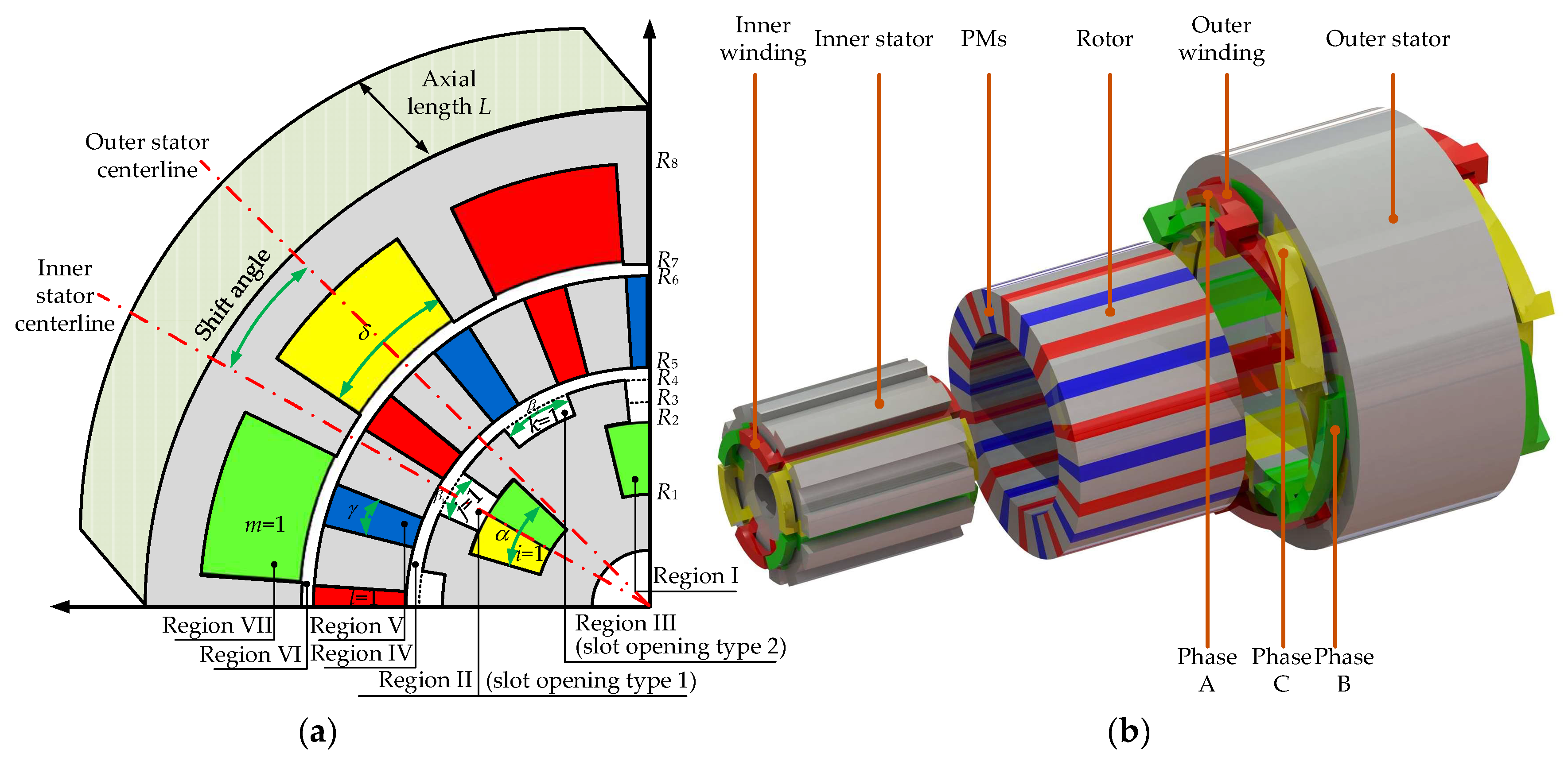
Figure 1. DSSTVM topology. (a) Subdomain division parameters and shift angle definition in the studied DSSTVM; (b) 3D scheme and winding configuration of the studied DSSTVM.
Energies 17 01114 g001
Figure 2. Flow chart of the proposed method.
Energies 17 01114 g002
Figure 3. Magnetic field distribution of the studied DSSTVM calculated by the FEA. (a) No-load condition; (b) On-load condition.
Energies 17 01114 g003
Figure 4. No-load magnetic flux density distribution of the studied DSSTVM. (a) Radial and tangential component in the middle of the inner air gap; (b) Radial and tangential component in the middle of the outer air gap.
Energies 17 01114 g004
Figure 5. No-load magnetic flux density distribution of the studied DSSTVM. (a) Harmonic spectrum of the radial component in the middle of the inner air gap; (b) Harmonic spectrum of the radial component in the middle of the outer air gap.
Energies 17 01114 g005
Figure 6. Rated load magnetic flux density distribution of the studied DSSTVM. (a) Radial and tangential component in the middle of the inner air gap; (b) Radial and tangential component in the middle of the outer air gap.
Energies 17 01114 g006
Figure 7. Rated load magnetic flux density distribution of the studied DSSTVM. (a) Harmonic spectrum of the radial component in the middle of the inner air gap; (b) Harmonic spectrum of the radial component in the middle of the outer air gap.
Energies 17 01114 g007
Figure 8. Torque and power factor optimization of the studied DSSTVM. (a) Torque and power factor change with the variation in shift angle; (b) No-load back EMF waveforms.
Energies 17 01114 g008
Figure 9. Harmonic spectrum of no-load back EMF waveforms of the studied DSSTVM. (a) Inner stator; (b) Outer stator.
Energies 17 01114 g009
Figure 10. Rated load torque and harmonic spectrum of the studied DSSTVM. (a) Torque wave-forms of three different modes (mode 1, mode 2 and model 3); (b) Harmonic spectrum of the torque wave-form of mode 1; (c) Harmonic spectrum of the torque wave-form of mode 2; (d) Harmonic spectrum of the torque wave-form of mode 3.
Energies 17 01114 g010
Table 1. Geometrical Parameters of The Studied DSSTVM.
SymbolValueSymbolValue
R124.8 mmαπ/6 rad
R241 mmβ1π/9 rad
R345.3 mmβ2π/10 rad
R450.3 mmγ37π/900 rad
R550.9 mmδ37π/300 rad
R666 mmPr10
R775.2 mmPw2
N200Z12
L100 mmJz6 A/mm2
Disclaimer/Publisher’s Note: The statements, opinions and data contained in all publications are solely those of the individual author(s) and contributor(s) and not of MDPI and/or the editor(s). MDPI and/or the editor(s) disclaim responsibility for any injury to people or property resulting from any ideas, methods, instructions or products referred to in the content.