Abstract
In this paper, IEC 61511 was used to evaluate the hazards and risks associated with the continuous operation of the hydrolysis reactor system in the copper-chlorine thermochemical hydrogen production cycle, with a specific focus on the application of automated active safety systems and safety integrated systems. The analysis presented herein was performed using a speculative but representative hydrolysis piping and instrumentation diagram (P&ID) for the hydrolysis reaction, which was based on currently published systems as well as experience with experimental hydrolysis reactors. This analysis was then used to inform the design of a set of automated safety systems that provide the redundant operation of critical devices and can bring the hydrolysis to a safe shutdown state if needed.
1. Introduction
In recent years, there has been a significant move by nations around the globe to push to develop the hydrogen economy, not only to provide clean energy for automobiles and other forms of transportation but also to provide the necessary chemical feeds for industries such as petrochemical and fertilizer production. Additionally, hydrogen production has also been proposed as a way to decarbonize industries by using hydrogen as a low-carbon fuel or feedstock, or by generating hydrogen to offset emissions. To fully realize a global hydrogen economy, a vast amount of hydrogen production is needed to produce hydrogen that can be efficiently and economically produced at a large scale. Thermochemical hydrogen production has the potential to provide cheap and abundant hydrogen using thermal energy sources, such as industrial waste heat or nuclear energy [1,2,3,4]. Simulations by Rosen et al. predicted that a copper-chlorine-based thermochemical cycle could achieve efficiencies of 52% when paired with a generation IV super-critical water-cooled reactor (SCWR) [5]. Wu et al. [6] analyzed the copper-chlorine cycle using reaction kinetics and found that the efficiency with internal heat recovery was 47.31%. Economically, Wu found that labor cost was the dominating factor in operating costs [6]. Due to its low operating temperatures and thermal efficiency, the copper-chlorine thermochemical hydrogen production is well suited to operate in a co-generation installation, often with other thermal power systems or refrigeration cycles [3,7,8,9].
1.1. The Copper-Chlorine Thermochemical Hydrogen Production Cycle
The copper-chlorine (Cu-Cl) cycle is a thermochemical hydrogen production cycle that provides some key advantages to help push for large-scale hydrogen production. The Cu-Cl cycle uses a series of thermochemical reactions to drive the splitting of water into hydrogen- and oxygen-carrying molecules, and then releases the hydrogen and oxygen, ending by re-combining the intermediate salt to begin the cycle anew (Figure 1) [10].
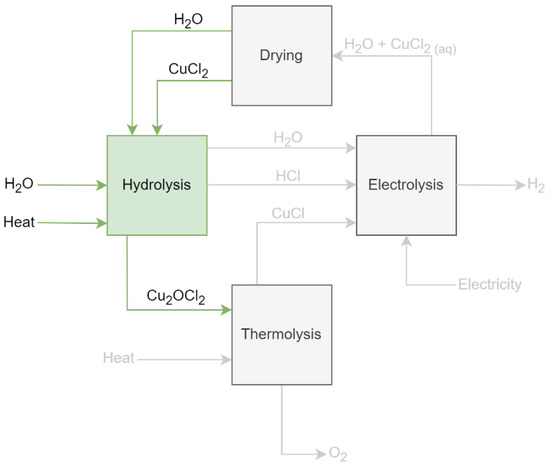
Figure 1.
The copper-chlorine cycle (hydrolysis highlighted).
The Cu-Cl cycle begins at hydrolysis, where a salt of copper and chlorine (CuCl2) reacts with steam at 400 °C in a gas–solid reactor, typically using a fluidized bed configuration. Figure 2 shows the basic components of the hydrolysis reactor, comprising a boiler, steam superheater, reactor, and condenser. The product of this reaction is a solid salt containing oxygen (Cu2OCl2) and hydrogen chloride (HCl). This reaction performs favorably at high concentrations of steam at a steam-to-copper ratio of 18, which is far beyond the stoichiometric ratio for the hydrolysis reaction. The product HCl flows with the excess steam to be condensed and used later in the cycle. The Cu2OCl2 is transported to the thermolysis reactor to be decomposed.
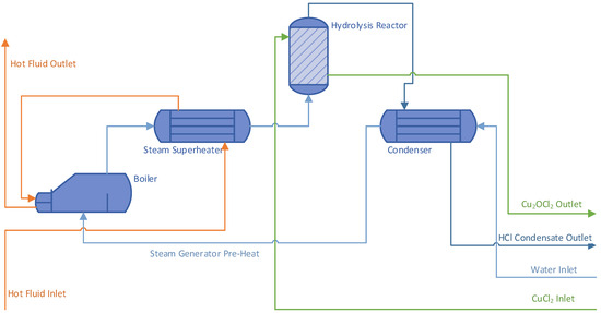
Figure 2.
Hydrolysis system overview.
In the thermolysis reactor, Cu2OCl2 is decomposed at 500 °C to release oxygen and form molten CuCl. The molten CuCl can then be quenched and recombined with HCl in the electrolysis reactor, where an electrochemical cell is used to release hydrogen and recombine the free Cl with CuCl, forming CuCl2, which is then ready to start the cycle again.
The materials involved in the Cu-Cl cycle include corrosive chlorine salts and aqueous HCl. These materials pose unique challenges for the downstream electrolysis step. Many of the reactors and components need to handle high-temperature highly corrosive solids and fluids, and damage to these systems can pose a major hazard to operators and equipment [11,12,13]. The chemicals involved in the Cu-Cl cycle also pose serious chemical hazards, with chronic illness resulting from repeated exposure [14,15,16]. Hydrogen chloride—produced in a gaseous form in the hydrolysis reaction and then condensed into a solution—is highly corrosive and can lead to chemical burns to the skin and eyes, and toxicity when inhaled [12]. Copper (I) chloride and copper (II) chloride are both skin and respiratory irritants and can cause serious eye damage [14,15]. It is therefore critical that systems are designed with inherent safety and multiple redundant safety systems to ensure safe operating conditions for all systems.
Most current safety analyses in the hydrogen industry focus on mitigating risks inherent to hydrogen, namely flammability and explosivity. In their paper, Franco Ferrucci [7] examined a hydrogen production and cooling co-generation installation and investigated the safety of systems that protect the plant operators from fire, explosion, and poisoning from the connected ammonia-based refrigeration cycle. This investigation referenced IEC 60079 explosive atmospheres, which provides standards for the use of equipment in environments with an explosive atmosphere [17]. Another investigation by Hai Tang [18] investigated safety systems for the Cu-Cl cycle installed with a nuclear reactor. Tang’s analysis extensively covered loss-of-coolant accidents, as well as safety instrumented systems to detect and prevent hydrogen leaks [18]. Matthijs van Wingerden et al. [19] recently demonstrated the effective chemical inhibition of explosive hydrogen atmospheres using propane and a fine powder of potassium carbonate and proposed that microspheres of potassium carbonate containing propane might be effective as a chemical inhibitor. These investigations are critical in ensuring that the hydrogen-containing systems of the Cu-Cl cycle are safe, especially with the possibility of flammable or explosive conditions. Considering the unique hazards posed by thermochemical cycles when compared with standard water-based electrolysis, further analysis is required to fully understand the safety of a Cu-Cl cycle thermochemical hydrogen production plant.
The conditions present in the hydrolysis reactor pose further challenges, as high-temperature steam must be generated by boilers and heat exchangers [2,11,20]. Due to the corrosive environment present throughout the Cu-Cl cycle, temperature-resistant materials, such as steel, will need to be coated or substituted for corrosion-resistant metals or glass process piping [11]. The use of high-temperature heat transfer fluid such as superheated steam could further pose a risk for flammability if volatile compounds such as grease, oil, or solvents are spilled near the heat transfer fluid pipes. The Cu-Cl cycle does not require these materials as part of the chemical cycle, but they may be required for operating hydraulic equipment or other such mechanical systems.
1.2. Safety Instrumented Systems
Three types of safety systems can be used in the Cu-Cl Cycle. These safety systems fall into the categories of passive safety design, active safety systems, and procedural safety. In passive safety, the systems and vessels are designed in such a way that they fail safely or are unable to be accidentally operated in an unsafe manner. Passive safety could take the form of physical interlocks that interfere with the operation if specific conditions are not met, and incompatible fittings that prevent accidental connections from being made that could lead to unsafe chemical reactions (e.g., oxidizers and fuels, acids and bases, chemicals, and wastewater). Active safety systems rely on devices that detect the conditions of a system and react in a way to bring the system back to safe operation. Safety instrumented systems (SIS(s)) are an example of an active safety system, constructed of a combination of sensors, logic solvers, and final elements (e.g., valves, actuators) [21]. SIS safety systems may be a combination of multiple safety instrumented functions (SIF(s)), which can be subsets of the overall SIS [21].
IEC Code 61511 outlines the SIS lifecycle, beginning with hazard and risk assessments, followed by allocating safety functions to protection layers [21]. This is followed by establishing the safety requirements of the SIS to be installed and designing the SIS according to these requirements. These steps make up Stage 1 of the SIS lifecycle, beyond which lies installation, validation, operation, modifications, and decommissioning. The scope of this investigation is to present the results of Stage 1 of the SIS lifecycle and focus specifically on the hydrolysis reaction alone.
2. Materials and Methods
2.1. Piping and Instrumentation Diagram
The starting point of this safety analysis was a piping and instrumentation diagram for the hydrolysis system (Figure 3). This diagram was developed based on experience with laboratory-scale hydrolysis reactors to represent the key capabilities and components of the hydrolysis reactor. The key system components are the boiler, the steam superheater, the hydrolysis reactor, and the condenser.
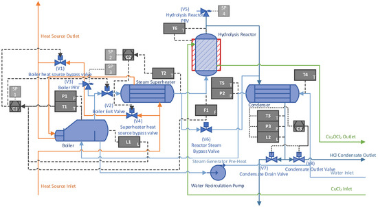
Figure 3.
Complete hydrolysis process and instrumentation diagram.
The boiler is represented here by a kettle reboiler with heat provided by a heat source fluid. Steam generation in the boiler is controlled by a PLC using thermocouples, pressure transmitters, and level sensors to determine the state of the boiler. The PLC can throttle the steam generation rate by engaging a bypass valve which redirects the heat source fluid around the boiler. The exit valve is engaged once the boiler has reached the desired temperature and pressure. A relief valve is supplied which will automatically dump pressure if the boiler reaches unsafe conditions.
The steam superheater is designed to provide a desired outlet temperature within the requirements of hydrolysis, typically around 400 °C. The superheater receives heat from the same heat source fluid stream, with control provided by a PLC which bypasses the heat source fluid around the superheater to control the temperature.
The hydrolysis reactor in this model is a simple design with temperature control provided by heating fluid circulating through the reactor body and additional heat provided by electrical power as needed. A relief valve is supplied to the hydrolysis reactor to ensure it does not reach unsafe pressures.
The condenser system in this model is used to cool and condense the mixture of steam and hydrogen chloride produced by the hydrolysis reaction. The condenser is specified to provide heat recovery by heating the water before it enters the boiler. Additional cooling can be provided by a circulating coolant loop if needed.
2.2. Hazard Analysis and Selected Top Events
With the system defined, it was checked against a list of potential hazards, and the hazards were identified and linked with specific subsystems. Each of the hazards was then ranked by severity and probability to select which hazards represented the highest risk, and these selected hazards were collected to represent top events. This hazard analysis was performed following guidelines for chemical process industry safety [22]. Table 1 shows an extract of the hazard analysis performed on the hydrolysis system, focusing on the highest-risk top events.

Table 1.
Extract of hydrolysis hazard analysis.
The results from the hazard analysis are tabulated in terms of potential hazards, subsystems affected by them, potential cause, result, and probability of the occurrence of the hazard. The final three columns are corrective or preventative measures, broken down into potential passive, active, and procedural measures.
The “Boiler Blast” top event was selected from the hazard analysis for further analysis. This was selected due to the high probability and severity of the consequences. This top event is also representative of the unique challenges presented by the Cu-Cl cycle over conventional hydrogen production methods.
2.3. Fault Tree Analysis and Event Probability
The top events were then organized on a fault tree to determine which combinations of failures could lead to the event occurring. The fault tree (Figure 4) contains events and logical operators, forming a series of paths through the fault tree termed minimal cut sets (MCS). A minimal cut set is a path through the fault tree that describes which combination of basic events must occur for the top event to occur. These events include failures such as computer errors, operator errors, or the failure of valves or sensors. For the case of the valves, since 3 possible failures could lead to the failure of the valve, each type of valve error is combined into a generic valve failure (V). The individual components and their failure rates are listed in Table 2.
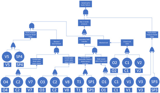
Figure 4.
Fault Tree Analysis for Catastrophic Boiler Failure.

Table 2.
Selected components and failure rates.
To determine the probability of the failure, each minimal cut set is broken into its originating failures, each with a known probability of failure per year, which can be combined to determine the overall probability of the minimal cut set to occur per year. Based on the form of the fault tree, there are a total of 56 unique minimal cut sets.
Figure 5 shows an example of one of the minimal cut sets, in this case, MCS 18. In this case, T1, C1, and V3 must all occur for this MCS to lead to catastrophic boiler failure. The combination of these failures has a probability defined by the product of the basic events,
To determine the probability of the top event, the product of all the MCS probabilities is
This leads to the cumulative probability of the top event, which represents the probability of the top event to occur per year.
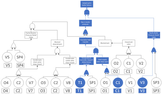
Figure 5.
Example minimal cut set (MCS 18).
2.4. Safety Instrumented System
To lower the risk associated with the system, a safety instrumented system (SIS) can be designed to add a layer of redundancy and reliability to ensure that failures of individual components do not accumulate to lead the system to fail. These additional systems should never be operated under standard process conditions and should be evaluated periodically to ensure that the system is available when needed. Once the probability of the chosen top event is determined, a safety instrumented system will be designed to address the possible paths that lead to a catastrophic boiler failure. This will take the form of independent sensors, controllers, and valves which are never used during normal processes but can render the system safe if needed. When possible, redundancy should be used, with multiple valves capable of rendering the system safe in different ways.
3. Results
3.1. Fault Tree Analysis Results
While the boiler was in line with the requirements for pressure relief devices set out in the ASME overpressure protection code for boilers UG-125, the boiler was found to still be unsafe and not in line with SIL 3 safety requirements [25]. With only basic safeguarding (simple pressure relief valve), the probability for the boiler blast top event was 77.4% per year. This probability can be evaluated as risk,
where R is risk, in CAD, P is Probability, and C is the cost of consequences. To estimate the cost of consequences, Table 3 was created with the costs associated with potential consequences, and the total cost.

Table 3.
Cost of Catastrophic Boiler Failure.
This table uses typical values for occupational safety and health administration compensation for worker injuries and rough estimates for the cost of the incident to come up with a rough total cost of over CAD 5 million. The total risk per year is therefore CAD 2.1 million.
To avoid a catastrophic failure and the long-term environmental damage that may be caused, a suitable safety integrity level (SIL) must be selected. The IEC standard on process industries, IEC 61511, defines SILs as shown in Table 4 [21].

Table 4.
Target Risk [21].
Since each SIL involves the further application of costly safety systems, a careful selection to reach a balance must be performed. Considering the high cost of consequences that may result in the case of a boiler failure, this balance will be selected at an overall target SIL of SIL 3, between 10−4 and 10−3, representing a risk of between CAD 400 and CAD 4000 per year. While this is considered unnecessary for some process industries [27], the Cu-Cl cycle has several risks and hazards to consider. The Cu-Cl cycle is also anticipated to co-locate with the nuclear industry, which necessitates the adoption of very high safety standards.
3.2. Proposed System Design
To bring the Cu-Cl hydrolysis boiler in line with the desired safety integrity level (SIL 3), the safety instrumented system designed above was integrated. Figure 6 shows the components of the SIS as installed, with SIS-specific components in red text.
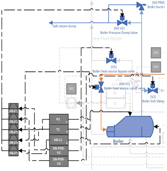
Figure 6.
Piping and Instrumentation Diagram with SIS SIF’s 1–6.
To achieve the desired safety integrity level, a safety instrumented system (SIS) was designed with a selection of safety instrumented functions (SIFs). These functions focus on addressing equipment failures and providing redundant sensors, controllers, and valves to keep the boiler in a safe operating condition. Each of the SIFs (see Table 5) result in a system trip, which commands that the SIS-powered pressure relief valve opens to dump pressure and that the heat supply valve is closed to shut off the flow of heat into the boiler. This provides a level of redundancy as each of these actions will help to bring the system back to a safe state. If the powered pressure relief valve fails to act, an additional safety device can be used as a last resort. This additional safety device is a rupture disc, a type of non-reclosing pressure relief valve that is focused on providing a last-resort failsafe in case all SIFs fail and the system is approaching an unsafe state. As the rupture disc is non-reclosing, the rupture disc would be set to rupture at a high enough pressure to be the last safety device to trip, but still low enough to avoid damage to the system.

Table 5.
Safety Instrumented Functions.
3.3. Safety Instrumented Functions
These five safety instrumented functions would be used to improve the safety of the system. SIFs 1–5 are all systems that use SIS-specific sensors and five independent controllers to control the two SIS valves.
To evaluate these safety instrumented functions, each SIF was broken down into its components, and reliability data were collected for each of the components. Then, a fault tree (Figure 7) was constructed with minimum cut sets to determine the overall probability of failure on demand (per year) for the safety instrumented system and all the component functions.
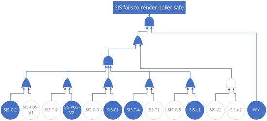
Figure 7.
SIS fault tree showing SIS-MCS20.
Each minimum cut set was considered together to lead to the total probability of failure on demand for the proposed safety system using a fault tree and series of minimal cut sets. This is possible because all these safety systems address essentially the same failure, and all are capable of rendering the boiler safe in the event of an overpressure or out-of-control heat source incident.
3.4. SIS Components
The proposed additional components to be used in the SIS system are as follows.
- SIS-POS-V1 A valve position sensor, which detects the position of the heat supply valve which provides heat transfer fluid to the boiler.
- SIS-POS-V2 A valve position sensor, which detects the position of the steam outlet valve which sends steam to downstream processes.
- SIS-T1 A temperature sensor, separate from process instrumentation, that the SIS system can use to detect an unsafe temperature.
- SIS-P1 A pressure sensor, separate from process instrumentation, that the SIS system can use to detect an unsafe pressure level.
- SIS-L1 A water level sensor, separate from process instrumentation, that the SIS system can use to detect an unsafe water level.
- SIS-V1 A SIS-controlled heat supply valve that can isolate the boiler from heat supply fluid if tripped. Fails CLOSED.
- SIS-V2 A SIS-controlled steam vent valve that can dump steam pressure to a safe tank and condenser if tripped. Fails OPEN.
- PRV A rupture disc, used as a redundant pressure relief valve. When the pressure reaches an unsafe level, the rupture disc breaks and dumps pressure to the safe steam dump. This device does not count as an SIF but is part of the additional safety system designed in this paper.
- SIS-C-(1–5) A set of programmable logic controllers that monitor the sensors and send commands to the valves. Any PLC can command a trip (one of five).
Table 6 shows the components of the designed SIS, which includes five safety instrumented functions and the additional rupture disc PRV. Each SIF shows the PFD of each component, and the PFD of the SIF itself failing is calculated using Equation (1), with the total PFD of the safety system calculated using Equation (2). SIF1 and 2 are specifically aimed at detecting valve action failures using valve position sensors; however, flow sensors may also be used to check for valve action on command. If a failure in Valves 1 and 2 is detected, the system commands a shutdown, with pressure being vented and heat source flow stopped. SIFs 3, 4, and 5 focus on instrumentation failures, with independent pressure, temperature, and level sensors with associated high limits. If the independent sensors detect unsafe conditions, SIFs 3, 4, and 5 will also command a shutdown. Taken together, the additional rupture disc and SIFs 1 through 5 have a total PFD of 1.49 × 10⁻⁴, or a total risk reduction factor (RRF) of 6714, which is in line with the desired safety integrity level.

Table 6.
Safety Instrumented Functions and Reliability.
The system with SIS installed has a probability of failure of 1.15 × 10⁻⁴, which brings the system in line with SIL3, with a risk reduction factor of 6702 (Equation (4)). Comparing a boiler with SIS to one without (Table 7), the SIS would save the plant CAD 2,119,271 per year. For the system to be economical, the cost of the components would have to be less than this amount.

Table 7.
Comparison of the boiler with and without SIS.
3.5. Cost of SIS System
With the additional SIS system presented in this paper, the overall risk of the boiler system for hydrolysis was brought down to an average yearly risk of CAD 597, with nearly 9000 years between failures. This demonstrates that the system with the additional SIS is considerably safe in the context of the selected catastrophic boiler failure top event.
The proposed SIS components listed in Table 8 only total CAD 4460, which, while high, does represent a good value since the system should decrease the frequency of failures to one every 8000+ years, saving the operator over CAD 4 million of risk per year.

Table 8.
Unit cost of SIS devices.
4. Conclusions
In this paper, a methodology was presented to determine the safety of plant systems in a representative copper-chlorine thermochemical hydrogen production cycle. The Cu-Cl cycle poses some unique challenges to operators, due to the chemicals and processes involved. Thus, it is necessary to not only focus on hydrogen safety—preventing unsafe levels of gases from accumulating or mixing and minimizing ignition sources—but also focus on temperature, pressure, and chemical hazards present in non-hydrogen-forming cycle components. The example chosen for this was the hydrolysis reaction in the Cu-Cl cycle, which contains highly corrosive acids and solids, high temperatures, steam generators, and superheaters. A full hazard analysis was performed to identify which hazards are present in the hydrolysis reactor, and what the likely risk of these hazards would be. The highest risk hazard—catastrophic boiler failure—was chosen as the top event for this investigation.
The representative hydrolysis reaction was modeled in detail with a speculative piping and instrumentation diagram based on experimental apparatuses in operation at Ontario Tech’s Clean Energy Research Lab, and data were gathered about the probability of component failure. This was used to construct a fault tree, which was analyzed using minimal cut sets to determine the probability of the top event occurring. This analysis yielded an annual probability of failure of 77.4%, with the failure having a total consequence of over CAD 5 million, resulting in a yearly risk of CAD 4 million.
Using this fault tree, a safety instrumented system (SIS) was designed to address single points of failure and add redundancy to systems. This safety instrumented system includes five functions, which focus on providing redundancy to the process valves, instrumentation, and controllers. These five functions were then analyzed using another fault tree for the SIS alone, which determines the likelihood of the system failing on demand. The SIS was found to have a risk reduction factor of 6714 or a probability of failure on demand of 0.0149%. Applying this system to the 77% probability of failure for the original boiler system, the resulting probability of failure was 0.0115% per year, with a time between failures of 8676 years. This is in line with safety integrity level (SIL) 3.
The system, with SIS installed, has a yearly risk of CAD 597, saving the operator over CAD 4 million per year, while only costing around CAD 4500 to install. Therefore, it can be concluded that the safety system as described in this paper is sufficient to maintain safety for the boiler subsystem in the Cu-Cl cycle.
Author Contributions
Conceptualization, L.F. and K.G.; Methodology, L.F.; Project administration, K.G.; Visualization, K.G.; Supervision, K.G.; Writing—original draft, L.F.; Writing—review and editing, K.G. and L.F. All authors have read and agreed to the published version of the manuscript.
Funding
This research received no external funding.
Data Availability Statement
The raw data supporting the conclusions of this article will be made available by the authors on request.
Acknowledgments
The authors would like to thank the contributions of laboratory assistants Curtis Straughan, Victoria Stinson, Alex Walker, and Amit Narsingh for their technical support in experimental apparatus at CERL which served as the inspiration for the example P&ID used in this investigation.
Conflicts of Interest
The authors declare no conflict of interest.
References
- Ferrandon, M.S.; Lewis, M.A.; Tatterson, D.F.; Nankani, R.V.; Kumar, M.; Wedgewood, L.E.; Nitsche, L.C. The Hybrid Cu-Cl Thermochemical Cycle. I. Conceptual process design and H2A cost analysis. II Limiting the formation of CuCl during hydrolysis. In Proceedings of the American Institute of Chemical Engineers Annual Meeting, Philadelphia, PA, USA, 16–21 November 2008. [Google Scholar]
- Farsi, A.; Dincer, I.; Naterer, G.F. Review and evaluation of clean hydrogen production by the copper-chlorine thermochemical cycle. J. Clean. Prod. 2020, 276, 123833. [Google Scholar] [CrossRef]
- Mokry, S.; Lukomski, A.; Pioro, I.; Gabriel, K.; Naterer, G. Thermalhydraulic analysis and heat transfer correlation for an intermediate heat exchanger linking a SuperCritical Water-cooled Reactor and a Copper-Chlorine cycle for hydrogen co-generation. Int. J. Hydrogen Energy 2012, 37, 16542–16556. [Google Scholar] [CrossRef]
- Miao, L.; Zhe, D.; Bowen, L.; Di, J.; Xiaojin, H. Cogeneration of Multi-Modular High Temperature Gas-Cooled Reactor Based on Cu-Cl Cycle and High Temperature Electrolysis. In Proceedings of the 2020 International Conference on Nuclear Engineering collocated with the ASME 2020 Power Conference, Virtual, 4–5 August 2020. [Google Scholar]
- Rosen, M.; Naterer, G.; Chukwu, C.; Sadhankar, R.; Suppiah, S. Nuclear-based hydrogen production with a thermochemical copper-chlorine cycle and supercritical water reactor: Equipment scale-up and process simulation. Int. J. Energy Res. 2012, 36, 456–465. [Google Scholar] [CrossRef]
- Wu, W.; Chen, H.Y.; Wijayanti, F. Economic evaluation of a kinetic-based copperechlorine (CueCl) thermochemical cycle plant. Int. J. Hydrogen Energy 2016, 41, 16604–16612. [Google Scholar] [CrossRef]
- Ferrucci, F. Design and implementation of the safety system of a solar-driven smart micro-grid comprising hydrogen production for electricity & cooling co-generation. Int. J. Hydrogen Energy 2024, 51, 1096–1119. [Google Scholar] [CrossRef]
- Onder, G.; Yilmaz, F.; Ozturk, M. Thermodynamic performance analysis of a copper–chlorine thermochemical cycle and biomass based combined plant for multigeneration. Int. J. Energy Res. 2020, 44, 7548–7567. [Google Scholar] [CrossRef]
- El-Emam, R.S.; Zamfirescu, C.; Gabriel, K.S. Analysis of copper chlorine electrolysis for large-scale hydrogen production. Int. J. Hydrogen Energy 2023, 48, 22720–22733. [Google Scholar] [CrossRef]
- Farsi, A.; Zamfirescu, C.; Dincer, I.; Naterer, G.F. Thermodynamic assessment of a lab-scale experimental copper-chlorine cycle for sustainable hydrogen production. Int. J. Hydrogen Energy 2019, 44, 17595–17610. [Google Scholar] [CrossRef]
- Stinson, V.; Owais, M. H2 Production via the Thermochemical Copper-Chlorine Cycle in a 40 Feet Long High-Cube Shipping Container—System Manual (Unpublished); Ontario Tech: Oshawa, ON, Canada, 2022. [Google Scholar]
- Linde Canada. Safety Data Sheet Hydrogen Chloride. 2015. Available online: https://www.lindecanada.ca/-/media/corporate/praxair-canada/documents-en/safety-data-sheet-linde-canada/e-4606-hydrogen-chloride-safety-data-sheet-sds.pdf (accessed on 1 February 2024).
- Thomas, D.; Kumar, G.; Ghuge, N.S.; Singh, K.K.; Mukhopadhyay, S.; Shenoy, K.T. Heat transfer characteristics and design aspects of thermolysis reactor in copper-chlorine thermochemical water splitting cycle. Int. J. Hydrogen Energy 2023, 48, 34286–34298. [Google Scholar] [CrossRef]
- ThermoFisher Scientific. SAFETY DATA SHEET Copper(II) Chloride Anhydrous. 2021. Available online: https://www.fishersci.com/store/msds?partNumber=AC206532500&countryCode=US&language=en (accessed on 1 February 2024).
- ThermoFisher Scientific. SAFETY DATA SHEET Copper(I) Chloride. 2010. Available online: https://www.fishersci.com/store/msds?partNumber=AC212421000&countryCode=US&language=en (accessed on 1 February 2024).
- Ghandehariun, S.; Wang, Z.; Rosen, M.A.; Naterer, G.F. Reduction of hazards from copper(I) chloride in a Cu–Cl thermochemical hydrogen production plant. J. Hazard. Mater. 2012, 229–230, 48–56. [Google Scholar] [CrossRef] [PubMed]
- IEC 60079. International Electrotechnical Commission: 2023. Available online: https://standards.iteh.ai/catalog/standards/iec/de6376a2-39e9-4b55-8dbd-7c91b4e8af70/iec-60079-11-2023 (accessed on 1 February 2024).
- Tang, H. Development of a PSA-Based Safety Assessment and Management Framework for a Nuclear-Based Hydrogen Generation System; University of Ontario Institute of Technology: Oshawa, ON, Canada, 2014. [Google Scholar]
- van Wingerden, M.; Skjold, T.; Roosendans, D.; Dutertre, A.; Pekalski, A. Chemical inhibition of hydrogen-air explosions: Literature review, simulations and experiments. Process Saf. Environ. Prot. 2023, 176, 1120–1129. [Google Scholar] [CrossRef]
- Wang, Z.; Daggupati, V.N.; Marin, G.; Pope, K.; Xiong, Y.; Secnik, E.; Naterer, G.F.; Gabriel, K.S. Towards integration of hydrolysis, decomposition and electrolysis processes of the Cu-Cl thermochemical water splitting cycle. Int. J. Hydrogen Energy 2012, 37, 16557–16569. [Google Scholar] [CrossRef]
- IEC 61511-1:2016. International Electrotechnical Commission: 2016. Available online: https://cdn.standards.iteh.ai/samples/20175/f68c8f8865b14e3c8f453f4e8bc8070d/IEC-61511-1-2016.pdf (accessed on 1 February 2024).
- Center for Chemical Process Safety. Guidelines for Engineering Design for Process Safety; John Wiley & Sons, Inc.: Hoboken, NJ, USA, 2012. [Google Scholar] [CrossRef]
- Chalupa, R. Failure Modes, Effects, and Diagnostic Analysis: 644 4-20mA/HART Temperature Transmitter; Rosemount Inc.: Shakopee, MN, USA, 2017. [Google Scholar]
- Smith, D.J. Reliability, Maintainability, and Risk: Practical Methods for Engineers Including Reliability Centred Maintenance and Safety-Related; Elsevier: Amsterdam, The Netherlands, 2005. [Google Scholar]
- Overpressure Protection. In ASME Boiler and Pressure Vessel Code; ASME International: New York, NY, USA, 2019; pp. 91–109.
- Estimated Costs of Occupational Injuries and Illnesses and Estimated Impact on a Company’s Profitability Worksheet; US Dept. of Labor: Washington, DC, USA. Available online: https://www.osha.gov/safetypays/estimator (accessed on 19 February 2024).
- King, A.G. Do You Really Need SIL 3? Chemical Processing. 2010. Available online: https://www.chemicalprocessing.com/automation/safety-instrumented-systems/article/11373539/do-you-really-need-sil-3 (accessed on 3 January 2023).
- Handbook of Reliability Prediction Procedures for Mechanical Equipment; United States Department of the Navy: West Bethesda, MD, USA, 2011.
Disclaimer/Publisher’s Note: The statements, opinions and data contained in all publications are solely those of the individual author(s) and contributor(s) and not of MDPI and/or the editor(s). MDPI and/or the editor(s) disclaim responsibility for any injury to people or property resulting from any ideas, methods, instructions or products referred to in the content. |
© 2024 by the authors. Licensee MDPI, Basel, Switzerland. This article is an open access article distributed under the terms and conditions of the Creative Commons Attribution (CC BY) license (https://creativecommons.org/licenses/by/4.0/).