Article

Enhanced Volts-per-Hertz Sensorless Starting of Permanent Magnet Motor with Heavy Loads in Long-Cable Subsea Applications †

Department of Electrical and Computer Engineering, University of Houston, Houston, TX 77204, USA
*
Author to whom correspondence should be addressed.
This paper is an extended version of our paper published in 2023 IEEE International Electric Machines & Drives Conference (IEMDC), San Francisco, CA, USA, 15–18 May 2023.
Energies 2024, 17(4), 957; https://doi.org/10.3390/en17040957
Submission received: 5 January 2024 / Revised: 3 February 2024 / Accepted: 14 February 2024 / Published: 19 February 2024
(This article belongs to the Section F3: Power Electronics)

Abstract

:
Permanent magnet (PM) motors are gaining prominence in subsea applications such as drilling, pumping, and boosting for oil and natural gas extraction. These motors are gradually replacing traditional induction motors. However, starting and operating PM motors at low speeds under heavy loads poses significant challenges. This is because of unknown initial rotor positions and resistive voltage drops due to the presence of a sinewave filter, transformer, and long cable. An unknown rotor position may result in temporary reverse speed, which may cause a loss of synchronism; therefore, initial rotor position estimation is preferable. Additionally, addressing the voltage drop issue requires careful voltage compensation to avoid transformer core saturation. In this paper, an enhanced V / H z starting of a PM motor is proposed with initial position detection (IPD) and voltage compensation to start the motor reliably with a heavy load. The proposed control method is verified with controller hardware in the loop (C-HIL) real-time simulation using a Typhoon HIL-604 emulator and a Texas Instruments TMS320F28335 digital signal processor (DSP) control card.

1. Introduction

Subsea motors are often located several kilometers away from variable speed drive (VSD) units, connected via a sinewave filter, transformer, and long cable. Induction motors (IMs) have been the primary workhorses in these applications for several decades, operated using simple control techniques to achieve smooth motor startups [1]. However, in order to enhance efficiency and achieve energy savings in motor drive systems, permanent magnet (PM) motors are gradually replacing IMs. Commercial PM motors designed for electric submersible pumps (ESPs) have demonstrated the potential to reduce power consumption costs by an average of 23% and energy consumption by at least 10–26% when compared to traditional IMs [2,3,4]. Despite the increased efficiency of PM motors, their control in these complex subsea systems presents many control challenges [5].
Several techniques have been developed to overcome the challenges associated with sensorless control strategies for permanent magnet motors (PMMs), particularly to start the motor from zero speed [6,7,8,9,10,11]. As most sensorless control strategies rely on back-EMF or flux linkage estimation, it can be challenging to estimate the motor’s position precisely when the motor is at standstill or low speed [12]. Therefore, specific starting strategies are essential in sensorless drive systems. In practical subsea applications, PM motors are typically controlled using volts-per-hertz ( V / H z ) control methods along with stability control and efficiency optimization or by a hybrid vector control method [13,14,15,16,17]. In hybrid control schemes, the PM motor starts using open-loop V / H z or open speed loop current ( I f ) control, and then the control method switches to sensorless vector control once the motor reaches a safe operating speed [18,19]. These sensorless control techniques generally provide satisfactory performance within the mid-to-high-speed range [20,21]. However, challenges arise during low-speed operation, particularly during PM motor startup under heavy loads. These challenges are primarily from transformer core saturation and resistive voltage drops within the system due to the presence of sinewave filters, transformers, and long cables. Also, when the rotor’s initial position is unknown at a standstill, the motor may experience temporary reverse rotation and result in decreased starting torque [22,23,24,25,26,27]. Moreover, if the initial rotor position has significant deviation and the rotor is not aligned with the applied frequency, the motor may lose synchronism [24,25]. Therefore, initial rotor position estimation at zero speed before starting can improve the starting performance of a motor with V / H z control.
The starting of a conventional permanent magnet (PM) motor using V / H z control is discussed in [28,29,30], where motor terminals are directly connected to the inverter’s output terminal. However, the primary control issue encountered when operating with long subsea cables under significant load is voltage drop across the cable, especially in lower-speed regions. Compensating for this voltage drop can help to achieve a smooth startup under load. Additionally, starting the PM motor at a slower electrical cycle is crucial to ensure that the rotor’s position is synchronized with the applied frequency [31,32]. In addition, the starting frequency must be selected at approximately 3 to 5% of the motor’s rated frequency together with an appropriate voltage magnitude to avoid transformer core saturation. Thus, choosing an optimal starting frequency is essential, considering the possible compromise between maintaining rotor synchronization and transformer core saturation [33].
Generally, a voltage boost or compensation is applied to the PM motor when starting it with a heavy load using V / H z control. However, if the compensation voltage is too high at startup, it can lead to an excessive current passing through the variable speed drive (VSD), which may result in system failure [34]. The appropriate compensation voltage must be carefully calculated to ensure a safe and reliable startup. Therefore, proper compensation voltage must be calculated for starting a PM motor under a heavy load to ensure safe and reliable operation as presented in [1]. In [34], the open speed loop current regulated control ( I f ) method is proposed for permanent magnet motor startup; however, in [35], the transition from open-loop to closed-loop vector control is proposed for long cable subsea applications. This paper proposes an enhanced V / H z control method for starting PM motors under heavy loads using both initial position detection (IPD) and voltage compensation. The IPD technique used is based on the injection of six pulses for accurate rotor position detection, and the voltage is actively compensated based on the active power current component to counteract the voltage drop in the system, thus resulting in a stable startup. The validity and effectiveness of the proposed control method are tested using a controller hardware-in-the-loop simulation using Typhoon (HIL-604) and Texas Instruments digital control card TMS320F28335.

2. Overview and Electrical Modeling of Subsea Drive Systems

In the offshore oil and gas industries, subsea motors are typically located at or under the seabed and connected to a VSD unit through a sinewave filter, transformer, and long cable [36,37,38]. Figure 1 represents the equivalent electrical model of a typical PM motor-based subsea drive system. Various low-voltage VSDs are available, with input voltages ranging from 230 V to 690 V and output powers ranging from a few kVA to MVA [39,40,41,42,43,44,45,46,47,48,49,50,51,52,53,54,55].
The sinewave filter, consisting of a filter resistor (Rf), filter inductor (Lf), and filter capacitor (Cf), is used for refining the pulse width modulated output voltage waveform from the inverter, for mitigating high-frequency harmonics, which can lead to voltage overshoot, and for suppressing electromagnetic interference (EMI). Sinewave filters are usually integrated into VSD units, and capacitor banks are typically connected in delta configuration to reduce size. It is recommended that the cut-off frequency of the sinewave filter be lower than the switching frequency of the inverter, but higher than the fundamental frequency of the motor to ensure efficient filtering [56]. As a result, the sinewave filter reduces the higher-order harmonics produced by the inverter while preserving the fundamental frequency of the output.
The three-phase step-up transformer in the system is essential for voltage transformation, which enables the control of medium-voltage subsea motors using low-voltage drives. It also ensures electrical isolation between the drive and motor, which enhances safety and reliability. Furthermore, the Δ-Y configuration of transformer connection is one of the most commonly used configurations to run a medium-voltage motor with low-voltage drive, as shown in Figure 1. The delta-star configuration offers the advantage of filtering out triplen harmonics to improve power quality and maintains consistent voltage despite unbalanced loads. Also, the transformers used in these applications generally have multiple taps on the secondary side [57] to allow for flexible voltage selection.
The long cable is modeled as Pi (π) circuits, which consist of resistance (Rc), inductance (Lc), and capacitance (Cc). This is because a long cable can be thought of as a distributed parameter network where resistance, inductance, and capacitance are spread along its length. The π circuit is a simplified approximation that captures the essential electrical characteristics of the cable over a certain frequency range, including charging currents due to cable capacitance and voltage drops due to the cable’s resistance and inductance.

3. Control and Challenges of Motor Drives for Subsea Applications

The standard industry practice for controlling PM motors in long cable subsea applications is to use a VSD with reliable control methods, such as a V / H z control with efficiency optimization or a hybrid vector control. However, a software damping control is employed to maintain the PM motor’s stability and keep it in synchronization throughout the speed range [30]. The control block diagram presented in Figure 2 describes the two-step process for starting the motor. (1) Initial position detection (IPD): The motor startup process begins with detecting the motor’s initial rotor position. IPD is a crucial first step to avoid reverse speed and enhance the reliability of motor control. (2) Starting with open-loop V / H z control: Once the initial position is known, the next step is to apply V / H z control to the motor.
As shown in Figure 2, the reference frequency is applied to the rate limiter which is responsible for limiting the acceleration and deceleration. The resulting output is denoted as f c o m m a n d . Subsequently, voltage V c o m m a n d is applied in proportion to the commanded frequency, except at very low speeds. At very low motor speeds, specifically below 0.04 PU, a boost voltage is applied to compensate for resistive voltage drops. The total voltage magnitude   V m is determined as the sum of commanded voltage V c o m m a n d and voltage compensation V c o m p . Meanwhile, the synchronous voltage angle θ c o m m a n d is calculated from the command frequency f c o m m a n d of applied voltage. However, the initial rotor position θ ^ r _ int is detected using the initial position detection (IPD) technique prior to starting the motor. During the IPD process, six switching space vector pulses are applied sequentially with specific time delays. Once IPD is performed successfully and identifies the rotor position, then the detected θ ^ r _ int is assigned to set the starting initial rotor position for applied voltage vector in the V / H z control strategy. However, there are several challenges that were considered for controller design. These challenges involve ensuring the accuracy of rotor position detection, the limitations of the voltage compensation mechanism, transformer core saturation, and the stability of the control system.

3.1. Voltage Drops in Subsea System Components

Motor drives for subsea applications are complex systems involving many electrical components such as a filter, transformer, and long cable. This complexity makes sensorless control of PM motors more challenging at low speeds, especially when started with a heavy load. The main reason for this is the saturation of the transformer core and the voltage drop in the subsea system components. The mathematical representation of voltage drops can be simplified by ignoring the shunt branches of system components. The per-phase equivalent resistive voltage drop referred to the primary side v R s y s is given by Equation (1) and the per-phase equivalent inductive voltage drop referred to the primary side v L s y s is given in Equation (2).
v R s y s = R f i i n v a + R t 1 i m a + n ( R t 2 + R c + R s ) i m a
v L s y s = ω r ( L f i i n v a + L t 1 i m a + n ( L t 2 + L c + L s ) i m a )
where R f ,   R t 1 ,   R t 2 , a n d   R s are the per-phase resistances of the sinewave filter, transformer primary winding, transformer secondary winding, and motor stator winding, respectively. Similarly, L f ,   L t 1 ,   L t 2 ,   a n d   L s are the per-phase inductances of the sinewave filter, transformer primary winding, transformer secondary winding, and motor stator winding, respectively. The notation n represents the transformer’s primary-to-secondary-turns ratio.
The total approximate voltage drop in subsea system components is approximately 10 to 15% of the motor terminal voltage. This voltage drop varies from system to system depending on various factors such as cable length, voltage rating, power rating, system components, etc. The voltage drops in the sinewave filter (~2 to 5%) [58,59,60,61], transformer (~1 to 3%) [62,63,64,65,66,67], cable (length-dependent, ~10%), and PM motor stator resistance. Additionally, on the input side of the drive, DC link voltage (vdc) fluctuation also introduces distortion to the motor and affects performance, which can be compensated for through software control. This DC link voltage drop may vary up to ~5–6% depending upon the size of the DC link capacitor (Cdc) [40,41,42,43,44,45,46,47,48,49,50,51,52,53,54]. Therefore, it is important to consider voltage drops in subsea system components for a smooth start of the motor.

3.2. Starting of Motor and Associated Challenges

When open-loop V / H z control is used to start PM motors in subsea applications, a voltage boost/compensation is generally added to compensate for the resistive voltage drop. However, the added voltage boost/compensation increases the V/Hz ratio, which may cause transformer core saturation and can withdraw huge inrush current from the variable speed drive and may cause system/component failure. Generally, the transformers used in these applications are designed to handle about 25% extra V/Hz ratio [42]. However, if the V/Hz ratio exceeds the maximum design limitation, the transformer core may become saturated.
For examining resemblances, the motor is started with and without consideration of transformer core saturation at 0.9 PU load torque, as shown in Figure 3. Figure 3a shows the smooth start of a motor without having back-and-forth rotation, i.e., in the case of an ideal core transformer. However, in the case of a practical transformer, there is a sustained high V / H z ratio during the voltage boost period, causing transformer core saturation. Because of core saturation, the transformer draws high magnetizing current, which is reflected in the primary current, as shown in Figure 3b. This phenomenon is evidenced by the substantial increase in magnetizing current, which is evident from the primary current’s waveform. As a result, rotor speed has large back-and-forth oscillations with a creepy sound and may damage the rotor shaft or cause a loss of synchronism. Also, once the transformer core becomes saturated, up to an hour may be required to demagnetize the core due to the unavailability of a dedicated test setup for demagnetization at the subsea field location. The issue of transformer core saturation also poses challenges in terms of system design, mandating considerations in the control strategy to prevent such occurrences and ensure the longevity and reliability of the motor drive system. Therefore, transformer core saturation must be considered while designing controllers.
The transformer was meticulously modeled as a high-fidelity subsea component in HIL-604. This model included the non-linearity and saturation of the transformer core to replicate the practical problems encountered in the subsea industry. If a non-linear transformer model is selected in HIL, core saturation is precisely modeled through a non-linear magnetizing flux with respect to the no-load current on the primary side of the transformer. A hysteresis upper curve is defined by the hysteresis flux values for the positive current and positive flux quadrant in Typhoon HIL. The magnetization curve of the transformer core model is depicted in Figure 4. This provides a non-linear equivalent model of transformer’s flux behavior under various loading conditions.

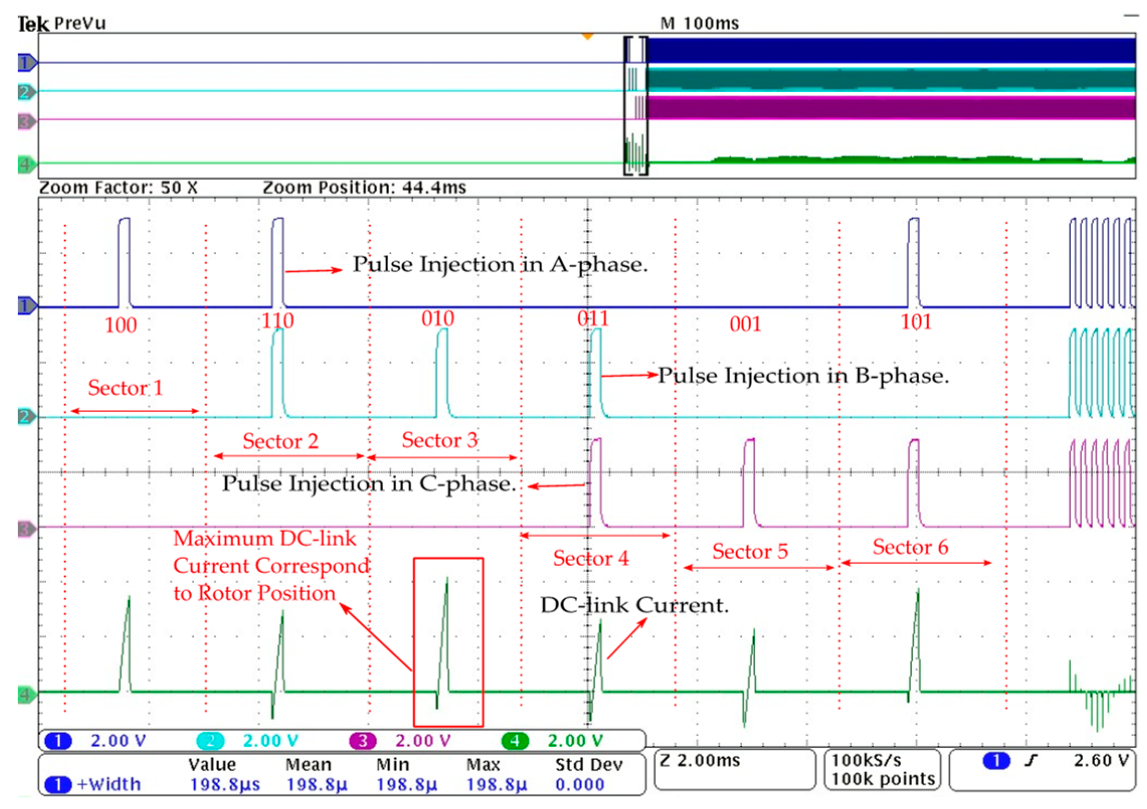
3.3. Proposed Starting Method with Initial Position Detection

In this paper, an enhanced V / H z starting of permanent magnet motor with a heavy load for a subsea motor drive system is proposed with an estimated initial rotor position, as shown in Figure 2. The accurate knowledge of the initial rotor position is crucial for effective motor startup and synchronization of the rotor with applied frequency without having to temporarily reverse speed [22]. Therefore, the rotor position estimation technique is required to detect the rotor position at zero speed before starting. In this regard, the six-pulsed signal injection-based estimation method is used for initial rotor position estimation, which leverages the anisotropic behavior of salient pole motors. Moreover, the inductance variation with rotor position and magnetic saturation is essential in detecting the rotor position. The detailed characteristics of magnetic flux and inductance variations based on the rotor position are explained in [23,24,25].
There are three major initial position detection methods based on DC-link current or terminal voltage measurement used to identify the rotor position [23,24,25,26,27]. These methods include the rise time measurement of DC-link current, terminal voltage pulse width detection, and peak current measurement of DC-link current. In the first method, a threshold value for the DC-link current is established, and the first of the six current pulses to reach this threshold indicates the rotor’s north pole position. The second method follows a similar approach, but instead measures the duration of terminal voltage pulses; the pulse with the shortest duration signifies the rotor’s north pole corresponding to that voltage vector [25,26]. Unlike the previous two methods, which depend solely on rise time, the third IPD method, based on peak current detection, considers the measurement of the DC-link current’s peak. Here, the duration of the voltage vector must be long enough to allow the current pulses to both rise and fall, with the highest DC-link current pulse out of the six determining the rotor’s position.
Figure 5a shows the controlled space voltage vectors with corresponding sectors and rotor positions; when the rotor position changes, then the amplitude of stator current changes due to the anisotropy behavior of the motor according to rotor position. This causes a variation in the peak value of the DC-link capacitor current, as shown in Figure 5b. To detect the initial rotor position, six pulses of space vector pulse width modulation (SVPWM) are applied sequentially by selecting the proper duration of pulses. The rise time of the DC-link current is decided by the applied pulse duration, and the minimum duration can be selected as the equivalent time constant of the system [22].
Initial rotor position detection employs short pulse injection based on space vector modulation, utilizing DC-link current measurements. However, the pulse duration is constrained by the sinewave filter’s cut-off frequency of 920 Hz (1087 µs) and transformer core saturation. The minimum duration of the injected pulses must be longer than the filter’s time constant (1087 µs), while the maximum duration is bound by the transformer’s limitations. After multiple iterations, an optimal injection pulse period is selected as 2800 µs (357 Hz) for HIL validation, with an on-time pulse duration of 200 µs (5 kHz) and an off-time of 2600 µs (385 Hz). The off-time duration ensures that the DC-link currents decrease to zero before the commencement of the subsequent pulse.
The initial rotor position can be identified by detecting the maximum DC-link capacitor current and corresponding sector, which gives the rotor position with ± 30 °   electrical resolution. The maximum DC-link current I d c _ m a x is the result of the maximum peak value of the current in six pulses of currents during the initial position detection. There are six space voltage vectors (V(100), V(110), V(010), V(001), V(011) and V(101)), which are applied during IPD to give six pulses of I d c . In the controller, a search algorithm is used to find the maximum value of the current among the six pulses of I d c currents, which is assigned as the value of I d c _ m a x . For instance, if the north pole of the rotor lies within sector 2, this implies that the corresponding DC-link current should have maximum peak value among all six current pulses during initial position detection (IPD), as illustrated in Figure 5.
The flowchart of the implementation stage of initial position detection can be seen in Figure 6. This stage is required for a stable and safe start by minimizing temporary reverse speed. After detecting the rotor position, the applied voltage vector is initialized from the known rotor position. The IPD process is initiated by setting the maximum DC-link current I d c _ m a x = 0 and sector number s = 1. Following this, voltage vectors are applied, and the peak DC-link current is measured for each vector. The goal is to identify the maximum peak current across all six currents. Also, a sufficient time delay must be applied between two voltage vectors to ensure the current reaches zero before initiating the next vector. This procedure is repeated for each of the six vectors.
Once all six sectors have been tested, it is determined that the rotor position is within the sector Smax corresponding to the highest recorded I d c _ m a x . The system then waits for the DC-link current to drop to zero. This is a crucial step to ensure that any residual current has dissipated before proceeding. This IPD stage ensures the accurate detection of the rotor’s initial position, without rotor movement. This stage is required for a stable and safe start by minimizing temporary reverse speed. After detecting the rotor position, the applied voltage vector is initialized from the known rotor position.

3.4. Control Performance and Boundary Conditions

Several boundary conditions must be considered for the stable operation of the motor with V / H z control as open-loop V / H z is very prone to instability and oscillations. An active power perturbation-based software damping has been incorporated in controls to prevent the motor from instability and rotor oscillations [30]. Rotor speed is extracted from active power and added to the reference speed with negative polarity to damp out the rotor oscillations. Also, a rate limiter is used to ramp up the reference speed, which helps the rotor to synchronize with the applied frequency, as shown in the flowchart in Figure 7.
The first step is to estimate the rotor position before starting, and the second step is to start the motor with V / H z from the estimated rotor position. Next, the starting frequency f s t a r t is obtained from the user and the condition in Equation (3) is checked.
f s t a r t _ min f c o m m a n d f s t a r t _ max
The starting frequency should be selected to prevent transformer core saturation, while the rotor should remain synchronized with the applied frequency. The minimum starting frequency is given in Equation (4).
f s t a r t _ min = f t r a n s _ r a t e d V m V t r a n s _ max
In this context, V t r a n s _ m a x represents the maximum permissible phase voltage of the transformer and f t r a n s _ r a t e d is the transformer’s rated frequency. For given values of V t r a n s _ m a x at 1.6 PU (which is 125% of the rated primary voltage) and a f t r a n s _ r a t e d of 60 Hz for a transformer, with the worst-case boost voltage being applied at 0.08 PU, the minimum starting frequency can be calculated as 0.025 PU. The base voltage and frequency are selected as 375 V and 120 Hz, respectively. Similarly, the maximum starting frequency can be selected based on the equation presented in [34], which is given as Equation (5).
f s t a r t _ max = 1 π p o l e _ p a i r s ( τ max τ l o a d ) J
τ max and τ l o a d are the maximum starting torque and load torque, whereas J denotes the inertia of the motor. Note that Equation (5) is derived assuming the rotor is locked. If the condition in Equation (3) is satisfied, then proceed to the next step. Otherwise, adjust the starting frequency till it satisfies the condition. Generally, the recommended minimum starting frequency f s t a r t _ m i n is selected at ~3–5%, and the maximum starting frequency f s t a r t _ m a x is ~10% of the rated motor frequency for a reliable start. Once the motor starts, we obtain its commanded frequency ( f c o m m a n d ), which passes through the rate limiter acceleration block. After that, the magnitude of the controlled voltage can be calculated, which is given in Equation (6).
V m = V c o m m a n d + V c o m p
where
V c o m m a n d = n ( V / H z ) s l o p e f c o m m a n d
( V / H z ) s l o p e = V r a t e d f r a t e d
Here, the term f r a t e d is the rated electrical frequency of the motor. Voltage magnitude ( V m ) must not exceed the motor’s rated voltage ( V r a t e d ). Therefore, ( V / H z ) s l o p e is limited at 80% from the drive to ensure the drive’s output voltage does not exceed its rated value under any load, as shown in Equations (7) and (8). The objective is to allow V c o m p to accommodate an additional 20% voltage compensation at full load. To prevent transformer core saturation under any load condition, the following requirement must be met, as indicated in Equation (9):
( V m / f c o m m a n d ) ( V t r a n s _ max / f t r a n s _ r a t e d )
In Equation (10), the total compensation voltage ( V c o m p ) is the sum of the voltage drop in the DC-link voltage ( V c o m p _ d c ) and the voltage drop in system resistance V c o m p _ R .
V c o m p = V c o m p _ d c + V c o m p _ R
Voltage compensation V c o m p _ d c can compensate for the voltage drop in the inverter caused by input voltage sag and DC bus ripples. Resistive voltage drops V c o m p _ R at no load are minimal due to the reduced active current component ( i m c o s ), thereby reducing resistive voltage drop. Additionally, maximizing the power transferred to the motor occurs when current ( I m ) and voltage V m are in the same phase, as shown in Figure A1 of Appendix A. The per-phase resistive voltage drop in the phase with the active power component is given in Equation (11):
V c o m p _ R = R s y s i m cos φ
where R s y s _ e q is the system equivalent resistance referred to the primary side of the transformer.
The voltage added for resistive voltage drop compensation is a function of the power factor. Adjusting the power factor in line with the load aids in avoiding transformer core saturation during heavy load operations. This adaptive approach to voltage compensation optimizes motor performance during startup. The reference voltages for the two-axis stationary reference frame (Alpha–Beta frame) are described in Equations (12) and (13):
V α _ r e f = V m cos θ c o m m a n d
V β _ r e f = V m sin θ c o m m a n d
where V α _ r e f and V β _ r e f are used to generate the space vector pulsed width modulation (SVPWM) for the inverter switching control.

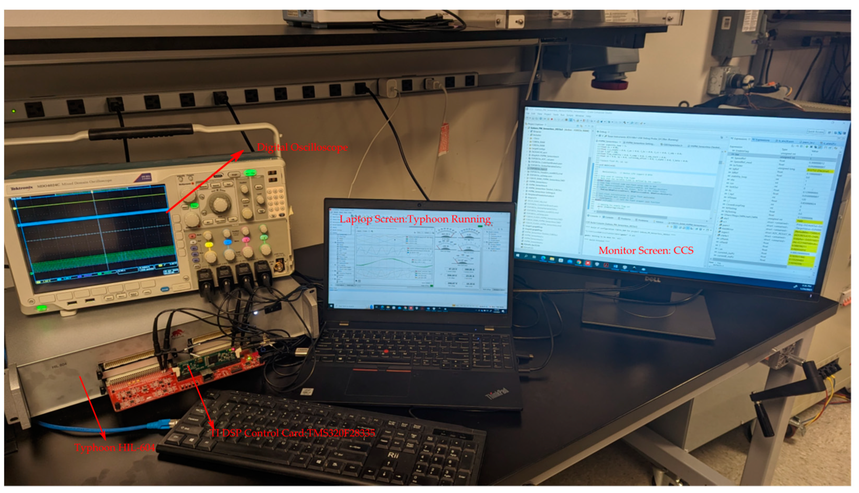
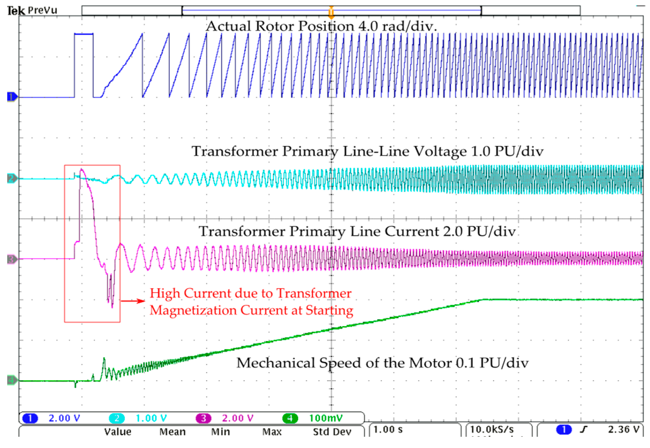
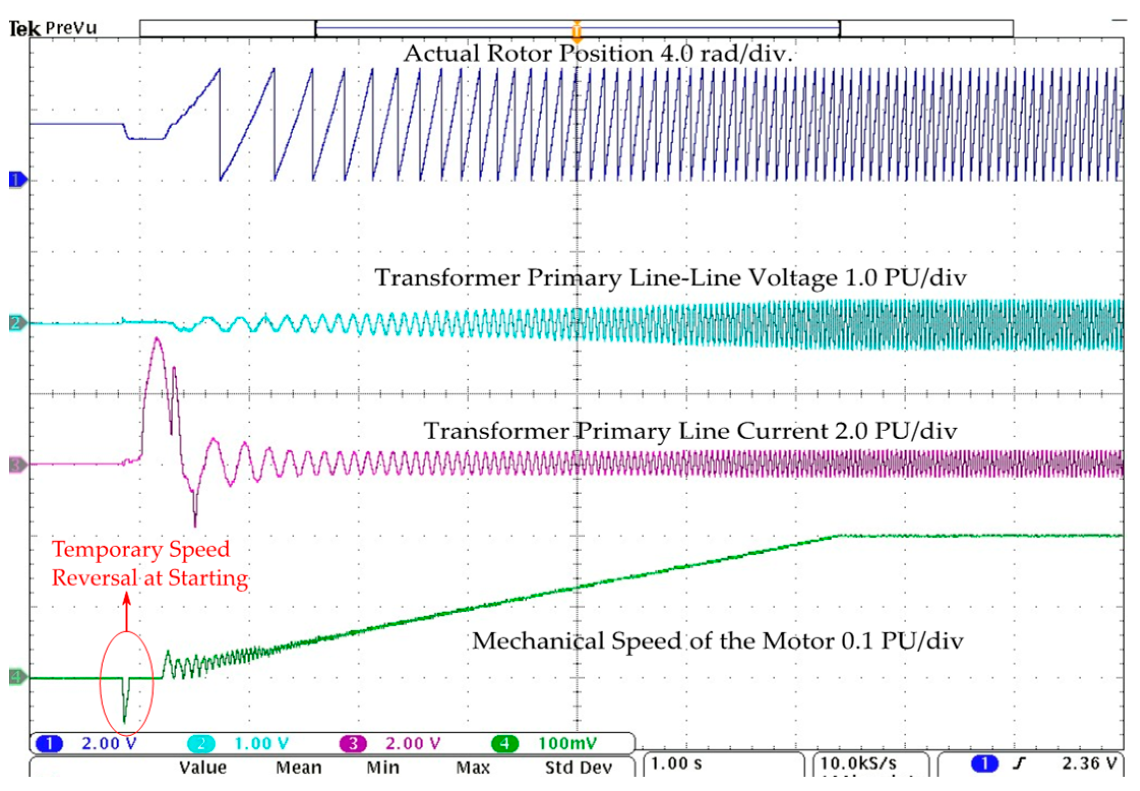
4. Validation with C-HIL

The proposed starting method is validated with controller hardware in the loop (C-HIL). The experimental setup, as illustrated in Figure 8, comprises the Typhoon HIL-604 and a Texas Instruments TMS320F28335 digital signal processor (DSP). The power circuit components, including the drive, sinewave filter, transformer, cable, and PM motor, are emulated in the Typhoon HIL-604, while the control circuit resides in the DSP. Certain assumptions were made in HIL modeling: the model does not account for the effects of temperature and pressure, and cable parameters are treated as lumped in practical applications. Measured analog signals, like voltages and currents, are converted into digital signals using ADC channels via the Typhoon interface board HIL DSP 180. Additionally, digitally controlled PWM pulses are delivered through this same interface board to control the emulated motor drive. The proposed control scheme is validated for an interior PMSM motor with the following specifications: rated power 90 kW, voltage 3.2 kV, and frequency 120 Hz. The parameters used for validation in this paper are listed in Table A1, Table A2, Table A3 and Table A4 of Appendix B.
This HIL model does not account for the effects of temperature and pressure. Also, the cable parameters are considered lumped, but in practical applications, they will be distributed in nature. But the parameters are selected in the operating conditions so that they have minimal effect on the control. As such, these HIL models are most effectively employed for controller testing before actual implementation in real-world applications, helping to preemptively mitigate any potential damage.
The cut-off frequency was chosen as 950 Hz, which is appropriate for a 5 kHz switching frequency and 120 Hz fundamental frequency. The motor was started with a minimum starting frequency f s t a r t _ m i n of 0.04 per unit (PU), applied voltage boost of 0.08 PU, load torque of 0.3 PU, and a command frequency of 0.2 PU. The waveforms of the rotor position, transformer primary line-to-line voltage v m a b , transformer primary line current i m a , and motor mechanical speed obtained through ADC channels of the HIL-604 device at the starting of the motor are shown in Figure 9.
The overshoot of the transformer current on the primary side is primarily due to the inrush current at startup, although it may also have been caused by core saturation. If the current overshoot lasts for longer, it could prevent the motor from starting properly. Figure 9 and Figure 10 present the waveforms of V / H z with voltage compensation based on the active power current component for the initial rotor position set at 0 ° and 180 ° electrical angle, respectively, at 0.30 PU load torque. It is observed that the rotor has a temporary reverse movement, which causes sustained back-and-forth oscillations in rotor speed and may lead to the loss of synchronism. Also, the large deviation of the initial rotor position causes a higher magnitude of speed in the reverse direction. Therefore, initial position detection is needed to avoid temporary reverse rotor speed and start the motor seamlessly.
Six consecutive pulses were applied at zero speed to detect the rotor position, as depicted in Figure 11 and Figure 12. As discussed earlier, the maximum value of the DC-link current decided the rotor position. Two random positions ( 180 ° and 210 ° ( e l e c t r i c a l ) were set in HIL to identify the rotor’s initial positions. The corresponding waveforms of injected signals and DC-link currents are shown in Figure 11 and Figure 12, respectively. It can be observed that the maximum values of DC-link current for 120 °   and 210 °   are in sector 3 and sector 4, respectively. Once the rotor position was known, then V/Hz control was activated with the estimated initial rotor position. The results for the modified proposed V / H z with voltage compensation and IPD are shown in Figure 13 and Figure 14 for the initial rotor position set at 0 ° and 180 ° , respectively. It can be observed in Figure 14 that the magnitude of reverse speed had minimized even in the case of 180 ° phase shift. Similar results are shown in Figure 15, Figure 16, Figure 17 and Figure 18, which illustrate the starting of the PM motor from different initial rotor positions of 60 ° , 120 ° , 210 ° , and 270 ° , respectively. The initial rotor positions can be determined by observing the waveforms before starting the motor, with each waveform providing unique insights. Additionally, the transformer’s primary current may exhibit different starting behaviors. Across all these scenarios, the motor starts reliably, confirming the effectiveness of the starting method. Therefore, the modified V/Hz with IPD and voltage compensation can improve the starting performance. In the waveforms, the actual rotor speed shown is measured from the HIL device for comparison purposes only, but in real subsea applications, the rotor position/speed is unknown.

5. Conclusions

In this paper, a modified V / H z control for starting PM motors with IPD and active power current component-based voltage compensation is proposed. An improvement in motor starting with heavy loads is achieved without saturating the transformer core or losing synchronism. Also, the temporary reversal of speed is avoided by detecting the initial rotor position. The results are presented for the V / H z starting of a PM motor with voltage compensation considering the effects of the sinewave filter, transformer, and long cable. The transformer magnetization curve and related challenges are also highlighted. Additionally, the results are also presented for different initial rotor positions with and without IPD. The proposed control method is verified with controller hardware in the loop (C-HIL) simulation using Typhoon HIL-604 and a TMS320F28335 digital signal processor control card.

Author Contributions

Conceptualization, validation, and writing—original draft preparation V.S. and G.S.; writing—review and editing, K.R. and G.S.; supervision, K.R. All authors have read and agreed to the published version of the manuscript.

Funding

This research received no external funding.

Data Availability Statement

Dataset available on request from the authors.

Conflicts of Interest

The authors declare no conflict of interest.

Appendix A

Figure A1. Phasor diagram of voltage and currents.
Energies 17 00957 g0a1
The instantaneous active power current component i m c o s φ in terms of the measured line currents on the primary side of the transformer, i m a and i m b , is calculated as
i m cos φ = 2 3 [ i m a cos θ c o m m a n d + i m b cos ( θ c o m m a n d 2 π 3 ) ( i m a + i m b ) cos ( θ c o m m a n d + 2 π 3 ) ]
where θ c o m m a n d is the position of the applied voltage vector of speed ω c o m m a n d in the stationary reference frame. The phasor diagram is shown in Figure A1, showing voltages and currents with their respective angles. In this scenario, the actual rotor position, denoted as θ r , lags the commanded angle, θ c o m m a n d . The amplitude of the applied voltage vector is in the phase with the current vector magnitude I m . The symbol δ represents the load angle, which varies according to the applied load and can be adjusted by the active power current components.

Appendix B

Table A1. ESP-PM motor parameters.
Motor power90 k W (3ph)
Motor rated voltage3200 V L L
Motor rated current17 A
Base/Nominal frequency120 H z
Motor resistance3.5 Ω
Motor (Q-axis) inductance L q 55.2 m H
Motor (D-axis) inductance L d 43.4 m H
Back EMF2900 V L L
No. of poles4
Moment of inertia J0.0275 K g . m 2
Viscous friction coefficient 0.05 N m s
Table A2. Transformer parameters (210 kVA).
Primary Voltage Side (V)Secondary Voltage Side (V)No Load Loss
(W)
Load Loss (W)% Impedance
480220065032003.8
260031103.95
300030003.85
340029053.92
370029003.75
390029003.72
Table A3. Long cable parameters (pi-model).
Conductor size#4 AWG
Inductance 0.14 ( m H / 1000 f t )
Capacitance 80 ( n F / 1000 f t )
Resistance 0.3 ( Ω / 1000 f t )
Length of cable 10000 ( f t )
Table A4. Sine filter parameters (delta configuration).
ConfigurationDelta-connection
Inductance 40 ( u H )
Capacitance250 ( u F )
Resistance 0.02 ( Ω )
Cut-off frequency 950 ( H z )

References

  1. Singh, V.; Selvaraj, G.; Rajashekara, K. Enhanced Volts-per-Hertz Starting of Permanent Magnet Motor with Heavy Loads in Long Cable Subsea Applications. In Proceedings of the 2023 IEEE International Electric Machines and Drives Conference (IEMDC), San Francisco, CA, USA, 15–18 May 2023; pp. 1–7. [Google Scholar] [CrossRef]
  2. Permanent Magnet Motors for REDA ESP Pumps—Schlumberger. Available online: https://www.slb.com/-/media/files/al/product-sheet/permanent-magnet-motor-ps.ashx (accessed on 1 January 2022).
  3. PMM-PCP System—Borets. Available online: https://borets.com/wp-content/uploads/2021/01/BORETS-PMM-PCP-System.pdf (accessed on 28 July 2015).
  4. Baker Hughes. Magnefficient Permanent Magnet Motor. Available online: https://www.bakerhughes.com/production/artificial-lift/electrical-submersible-pump-systems/magnefficient-permanent-magnet-motor (accessed on 24 June 2020).
  5. Jahns, T.M.; Kliman, G.B.; Neumann, T.W. Interior permanent magnet synchronous motors for adjustable-speed drives. IEEE Trans. Ind. Appl. 1986, IA-22, 738–747. [Google Scholar] [CrossRef]
  6. Ogasawara, S.; Akagi, H. An approach to position sensorless drive for brushless DC motors. IEEE Trans. Ind. Appl. 1991, 27, 928–933. [Google Scholar] [CrossRef]
  7. Lee, W.-J.; Sul, S.-K. A new starting method of BLDC motors without position sensor. IEEE Trans. Ind. Appl. 2006, 42, 1532–1538. [Google Scholar] [CrossRef]
  8. Jang, G.H.; Park, J.H.; Chang, J.H. Position detection and start-up algorithm of a rotor in a sensorless BLDC motor utilizing inductance variation. IEEE Proc.-Electr. Power Appl. 2002, 149, 137–142. [Google Scholar] [CrossRef]
  9. Miki, I.; Inagaki, Y.; Nakashima, S. Sensorless initial rotor position estimation of surface permanent-magnet synchronous motor. IEEE Trans. Ind. Appl. 2000, 36, 1598–1603. [Google Scholar] [CrossRef]
  10. Tanaka, K.; Yuzawa, T.; Moriyama, R.; Miki, I. Initial rotor position estimation for surface permanent magnet synchronous motor. IEEE IAC 2001, 4, 2592–2597. [Google Scholar]
  11. Lai, Y.-S.; Shyu, F.-S.; Tseng, S.-S. New initial position detection technique for three-phase brushless DC motor without position and current sensors. IEEE Trans. Ind. Appl. 2003, 39, 485–491. [Google Scholar]
  12. Sugawara, J.; Kaimori, T.; Nishikata, S. A novel and simple initial rotor position detecting method for PMSMs. In Proceedings of the IEEE PEDS, Kuala Lumpur, Malaysia, 28 November–1 December 2005; pp. 612–617. [Google Scholar]
  13. Siemens. Medium Voltage Converters. 2016. Available online: http://www.industry.siemens.com/drives/global/en/converter/mv-drives/pages/default.aspx (accessed on 1 January 2021).
  14. TMEIC Corp. Medium Voltage AC Drives. 2013. Available online: https://www.tmeic.com/North%20America/259-Products%20MediumVoltageACDrives-116 (accessed on 1 January 2013).
  15. AMTECH. Medium Voltage Drives. 2013. Available online: http://www.amtechelectronics.com/product.aspx?sid=3 (accessed on 1 January 2013).
  16. Schneider Electric. Medium Voltage Variable Speed Drive. 2016. Available online: http://www.schneider-electric.com/en/productrange/61394-altivar-1200 (accessed on 1 January 2016).
  17. Toshiba. Medium Voltage Drives. 2016. Available online: https://www.toshiba.com/tic/industrial-systems/adjustable-speeddrives/mediumvoltage-drives/ (accessed on 1 January 2016).
  18. Ingeteam. Frequency Converters. Available online: http://www.ingeteam.com/Portals/0/Catalogo/Sector/Documento/SSE_258_Archivo_sbp15-catalogo-ingedrive.pdf (accessed on 14 October 2023).
  19. Yaskawa. Medium Voltage Drives. 2016. Available online: https://www.yaskawa.com/pycprd/products/mv-drives (accessed on 22 March 2016).
  20. Aijun, C.; Xinhai, J. A stable V/HZ control method for permanent magnet synchronous motor drives. In Proceedings of the IEEE Transportation Electrification Conference and Expo, Asia-Pacific (ITEC Asia-Pacific), Harbin, China, 7–10 August 2017; pp. 1–5. [Google Scholar]
  21. Wang, Z.; Lu, K.; Blaabjerg, F. A Simple Startup Strategy Based on Current Regulation for Back-EMF-Based Sensorless Control of PMSM. IEEE Trans. Power Electron. 2012, 27, 3817–3825. [Google Scholar] [CrossRef]
  22. Soni, U.K.; Tripathi, R.K. Sensorless control of high-speed BLDC motor using equal area criterion based precise commutation scheme with Fuzzy based phase delay compensation. Int. Trans. Electr. Energy Syst. 2021, 31, e13001. [Google Scholar] [CrossRef]
  23. Chen, Y.; Yang, T.; Fan, L.; Bozhko, S. Sensorless Control Design of High-Speed Electric Drives in Discrete-Time Domain for Mild-Hybrid Turboprop Aircraft Applications. IEEE Trans. Transp. Electrification 2022, 9, 3601–3619. [Google Scholar] [CrossRef]
  24. Cheng, K.-Y. Initial Rotor Position Detection for Permanent Magnet Synchronous Motors. U.S. Patent Application 12/689,411, 22 July 2010. [Google Scholar]
  25. Tursini, M.; Petrella, R.; Parasiliti, F. Initial rotor position estimation method for PM motors. IEEE Trans. Ind. Appl. 2003, 39, 1630–1640. [Google Scholar] [CrossRef]
  26. Bist, V.; Wekhande, S. Accurate Startup Techniques in a Sensorless Field-Oriented Control BLDC (Sinusoidal) Motor; Allergo Microsystems: Manchester, NH, USA, 2022. [Google Scholar]
  27. Chang, Y.-C.; Tzou, Y.-Y. A New Sensorless Starting Method for Brushless DC Motors without Reversing Rotation. In Proceedings of the 2007 IEEE Power Electronics Specialists Conference, Orlando, FL, USA, 17–21 June 2007; pp. 619–624. [Google Scholar] [CrossRef]
  28. Acarnley, P.; Watson, J. Review of position-sensorless operation of brushless permanent-magnet machines. IEEE Trans. Ind. Electron. 2006, 53, 352–362. [Google Scholar] [CrossRef]
  29. Janislav, S.E.G.A. Low to High Speed Operation of a Sensorless Brushless DC Motor. U.S. Patent 11,264,930, 1 March 2022. [Google Scholar]
  30. Perera, P.D.C.; Blaabjerg, F.; Pedersen, J.K.; Thogersen, P. A sensorless, stable V/f control method for permanent-magnet synchronous motor drives. IEEE Trans. Ind. Appl. 2003, 39, 783–791. [Google Scholar] [CrossRef]
  31. Ancuti, R.; Boldea, I.; Andreescu, G.-D. Sensorless V/f control of high-speed surface permanent magnet synchronous motor drives with two novel stabilising loops for fast dynamics and robustness. IET Electr. Power Appl. 2010, 4, 149–157. [Google Scholar] [CrossRef]
  32. Consoli, A.; Scelba, G.; Scarcella, G.; Cacciato, M. An effective energy-saving scalar control for industrial IPMSM drives. IEEE Trans. Ind. Electron. 2013, 60, 3658–3669. [Google Scholar] [CrossRef]
  33. Nair, S.V.; Hatua, K.; Prasad, N.V.P.R.D.; Reddy, D.K. A quick I-f starting of PMSM drive with pole slipping prevention and reduced speed oscillations. IEEE Trans. Ind. Electron. 2021, 68, 6650–6661. [Google Scholar] [CrossRef]
  34. Liu, J.; Dai, J.; Royak, S.; Schmidt, P.B.; Al-Nabi, E.; Nondahl, T.A. Design and Implementation of Position Sensorless Starting Control in Industrial Drives with Output Filter and Transformer for Oil/Pump Applications. IEEE Trans. Ind. Appl. 2019, 55, 471–479. [Google Scholar] [CrossRef]
  35. Liu, J.; Nondahl, T.A.; Dai, J.; Royak, S.; Schmidt, P.B. A Seamless Transition Scheme of Position Sensorless Control in Industrial Permanent Magnet Motor Drives with Output Filter and Transformer for Oil Pump Applications. IEEE Trans. Ind. Appl. 2020, 56, 2180–2189. [Google Scholar] [CrossRef]
  36. Selvaraj, G.; Duan, Y.; Liu, Y.; Rayner, M. Voltage Optimization Technique for a Permanent Magnet Motor used in an Electric Submersible Pump. U.S. Patent US 20200321824A1, 3 April 2020. [Google Scholar]
  37. Stellas, D.; Hansen, M.T.; Thiringer, T.; Stromsvik, T.; Ulvestad, H.B. Position-sensorless control of a submersible PMSM fed over a long cable and two transformers. In Proceedings of the European Conference on Power Electronics and Applications, Lappeenranta, Finland, 26–28 August 2014; pp. 1–10. [Google Scholar]
  38. Wilson, D.; Robinson, P.; Conrad, D.; Heideck, K. Deployment of MV drives in electrical submersible pumps in steam assist gravity drainage applications. In Proceedings of the Petroleum and Chemical Industry Technical Conference (PCIC), Calgary, AB, Canada, 18–20 September 2017; pp. 397–404. [Google Scholar]
  39. Singh, V.; Majumder, M.G.; Rajashekara, K.; Reddy, S.R.P. Parameter estimation for sensorless position control of PMSM drives with long cables in subsea applications. IEEJ J. Ind. Appl. 2023, 12, 303–311. [Google Scholar] [CrossRef]
  40. ABB. Low Voltage Drives. Available online: https://cdn2.hubspot.net/hubfs/1792768/PDF/abb-low-voltage-drives-product-guide.pdf (accessed on 1 January 2015).
  41. Siemens. Low Voltage Drives. Available online: https://assets.new.siemens.com/siemens/assets/api/uuid:01b48121-ad1a-4059-ade1-75c5fac219eb/SINAMICS-LV-Drives-Family-Brochure.pdf (accessed on 1 January 2020).
  42. TMEIC Corp. Low Voltage AC Drives. Available online: https://www.tmeic.com/products/tmdrive-10e2-dp (accessed on 6 January 2021).
  43. AMTECH. Low Voltage Drives. Available online: https://www.amtechdrives.com/product_pdf/axperteazyplus_brochure.pdf (accessed on 21 December 2022).
  44. ALSTOM. Low Voltage Drives: Intelligent Drive Technology. Available online: http://alsintec.com/documents/alstom/drives/Alspa%20MV1000.pdf (accessed on 4 March 2010).
  45. Schneider Electric. Low Voltage Variable Speed Drive. Available online: https://www.se.com/us/en/product-range/64501-altivar-process-680-afe-low-harmonic-drive/?parent-subcategory-id=86129#documents (accessed on 17 October 2023).
  46. Fuji Electric Europe. Low Voltage Variable Speed Drive. Available online: https://www.fujielectric.com/products/ac_drives_lv/north-america/ (accessed on 1 September 2017).
  47. Delta Electronics. Low Voltage Drive. Available online: https://filecenter.deltaww.com/Products/download/06/060101/Manual/DELTA_IA-MDS_CFP2000_UM_EN_20210325.pdf (accessed on 31 March 2020).
  48. Eaton. Low Voltage Adjustable Frequency Drives. Available online: https://www.eaton.com/content/dam/eaton/products/industrialcontrols-drives-automation-sensors/en-globalprime/eaton-drives-ecodesign-drives-mz040046-en-us.pdf (accessed on 1 March 2022).
  49. Toshiba. Low Voltage Drives. Available online: https://www.toshiba.com/tic/motors-drives/low-voltage-adjustable-speed-drives/lv-industrial-drives/as3 (accessed on 1 April 2022).
  50. WEG Group. Low Voltage Variable Speed Drive. Available online: https://www.weg.net/catalog/weg/US/en/Drives/Variable-Speed-Drives/System-Drives/CFW11-Pump-Genius/DRIVE-CFW110370T4SZ-PGM/p/14396171 (accessed on 3 November 2023).
  51. Hitachi. Medium Voltage Drives. Available online: https://www.hitachi-hirel.com/products/drives/low-voltage-drives/wj200-series-low-voltage-drive (accessed on 1 January 2023).
  52. Ingeteam. Low Voltage Frequency Converters. Available online: https://www.ingeteam.com/en-us/power-electronics/power-converters/pc28_6_488/ingedrive-lv800.aspx (accessed on 4 March 2010).
  53. Rockwell Automation. Low Voltage AC Drives. Available online: https://configurator.rockwellautomation.com/configurator/3C11204E8B2A4F2D8BBFFF57479C4B21/summary (accessed on 1 September 2020).
  54. Yaskawa. Low Voltage Drives. Available online: https://www.yaskawa.com/delegate/getAttachment?documentId=SIEPC71061737&cmd=documents&openNewTab=true&documentName=SIEPC71061737.pdf (accessed on 1 December 2022).
  55. Singh, V.; Majumder, M.G.; Rajashekara, K.; Siddavatam, R.P.R. Parameter estimation for sensorless position control of PMSM drives with long cable in subsea applications. In Proceedings of the International Power Electronics Conference (IPEC-Himeji 2022- ECCE Asia), Himeji, Japan, 15–19 May 2022; pp. 384–388. [Google Scholar]
  56. ABB Low Voltage Industrial Drive “All-Compatible ACS880 Single Drives”. Available online: https://new.abb.com/drives/low-voltage-ac/industrial-drives/acs880-single-drives (accessed on 22 March 2023).
  57. GE Power Conversion LV8 Platform “High Performance for Modular Drive for Industrial Applications”. Available online: https://www.gepowerconversion.com/sites/default/files/2022-01/GEA34852_LV8Platform_FS_High%20performance%20modular%20drive_EN_20220126_Rev2.pdf (accessed on 1 January 2022).
  58. Schaffner. LC Sine Wave Filter for Motor Drives. 2022. Available online: https://docs.rs-online.com/3b90/0900766b81539b2f.pdf (accessed on 4 March 2010).
  59. MSD, “Sine Wave Filter”. Available online: https://vfds.com/content/manuals/tci/MSD-Brochure.pdf (accessed on 1 January 2019).
  60. MTE Corporation. “Sinewave Filter Series A 200-600 VAC”, User Manual. Available online: https://www.mtecorp.com/wp-content/uploads/INSTR-020.pdf (accessed on 9 March 2009).
  61. TDK. EMC Filter 3-Line Filters Sine-Wave Output Filters 300/520 V AC, 4 A … 390 A, 40 °C. Available online: https://www.tdk-electronics.tdk.com/inf/30/db/emc_2014/B84143V_R_S229.pdf (accessed on 1 January 2021).
  62. Eaton. “Three-Phase Pad-Mounted Compartmental Type Transformer”. July 2015. Available online: https://www.eaton.com/content/dam/eaton/products/utility-and-grid-solutions/transformer/pad-mounted-transformer/Eaton-Pad-mounted-Transformer-Brochure-EN-US.pdf (accessed on 12 July 2015).
  63. Jefferson. Available online: https://jeffersonelectric.com/wp-content/uploads/LIT901_0117-Jefferson-Full-Catalog.pdf (accessed on 6 July 2023).
  64. Siemens. “Low Voltage Transformers with DOE 2016 Updates”, Series H and Series J Addendums. Available online: https://assets.new.siemens.com/siemens/assets/api/uuid:54e8601e-d006-4493-90dc-c0a918de491d/sie-ca-transformer-speedfax-supplement.pdf (accessed on 1 January 2016).
  65. Schnider. Medium Voltage Transformers Specification Guide. Available online: https://stevenengineering.com/wp-content/uploads/2019/02/45TMEDVOLT.pdf (accessed on 1 January 2019).
  66. REX POWER MAGNETICS, “DRY Type Transformer”. Available online: https://www.pccweb.com/wp-content/uploads/2021/01/Rex-Power-Magnetics-Catalog.pdf (accessed on 14 October 2020).
  67. ABB. Low Voltage Dry Type Transformers 600V Class Large Power. Available online: https://electrification.us.abb.com/catalog/buylog/10A_BuyLog_LVDryTypeTransformers.pdf (accessed on 1 January 2023).
Figure 1. Electrical circuit model of a subsea system with a filter, transformer, and long cable.
Energies 17 00957 g001
Figure 2. Block diagram of modified V/Hz control starting with voltage compensation and initial position detection.
Energies 17 00957 g002
Figure 3. Results on starting the motor with 90% of rated load torque (a) without transformer core saturation considered and (b) with transformer core saturation considered.
Energies 17 00957 g003
Figure 4. Magnetization curve of transformer in positive half cycle.
Energies 17 00957 g004
Figure 5. (a) Sector identification of rotor position in terms of the applied voltage vectors, and (b) DC-link current variations with respect to applied switching vectors of on time 200 µs and off time 2600 µs.
Energies 17 00957 g005
Figure 6. Flowchart of motor with initial position detection stage.
Energies 17 00957 g006
Figure 7. Flowchart of PM motor startup steps with open-loop V/Hz control.
Energies 17 00957 g007
Figure 8. Experimental C-HIL testbed setup with Typhoon HIL-604 and TMS320F28335 DSP control card.
Energies 17 00957 g008
Figure 9. Starting of motor from 0 initial rotor position without IPD.
Energies 17 00957 g009
Figure 10. Starting of motor from 180 ° initial rotor position without IPD.
Energies 17 00957 g010
Figure 11. DC-link current pulses corresponding to initial position at 120 ° .
Energies 17 00957 g011
Figure 12. DC-link current pulses corresponding to initial position at 210 ° .
Energies 17 00957 g012
Figure 13. Starting of motor from 0 initial rotor position with IPD.
Energies 17 00957 g013
Figure 14. Starting of motor from 180 ° initial rotor position with IPD.
Energies 17 00957 g014
Figure 15. Starting of motor from 60 ° initial rotor position with IPD.
Energies 17 00957 g015
Figure 16. Starting of motor from 120 ° initial rotor position with IPD.
Energies 17 00957 g016
Figure 17. Starting of motor from 210 ° initial rotor position with IPD.
Energies 17 00957 g017
Figure 18. Starting of motor from 270 ° initial rotor position with IPD.
Energies 17 00957 g018
Disclaimer/Publisher’s Note: The statements, opinions and data contained in all publications are solely those of the individual author(s) and contributor(s) and not of MDPI and/or the editor(s). MDPI and/or the editor(s) disclaim responsibility for any injury to people or property resulting from any ideas, methods, instructions or products referred to in the content.

