Article

Installation Cost and Heat Extraction Performance Analysis of H-Shaped PC Pile Ground Heat Exchangers for Small Buildings

1
Faculty of Engineering, Hokkaido University, Sapporo 060-8628, Japan
2
Ambiente Innovation Co., Ltd., 1-12-4 Ginza, Chuo-ku, Tokyo 104-0061, Japan
3
INOAC Housing & Construction Materials Co., Ltd., 4-9-27 Taihou, Atsuta-ku, Nagoya 456-0062, Japan
*
Author to whom correspondence should be addressed.
Energies 2024, 17(4), 891; https://doi.org/10.3390/en17040891
Submission received: 1 December 2023 / Revised: 4 January 2024 / Accepted: 7 January 2024 / Published: 14 February 2024
(This article belongs to the Section J: Thermal Management)

Abstract

:
Ground source heat pump systems are one of the renewable energy heat utilization technologies that can reduce the energy for HVAC and hot water supplies and consequently mitigate the progression of global warming. On the other hand, the development of ground heat exchangers that can be installed in small buildings with low installation costs is an important challenge for increasing the installation number of ground source heat pump systems in Japan. This study proposes H-shaped PC pile ground heat exchangers to reduce installation costs. The installation test and installation cost estimation of H-shaped PC pile ground heat exchangers showed that installation costs could be reduced to less than half compared to the conventional borehole double U-tube ground heat exchanger. The coefficient of heat extraction/injection of H-shaped PC pile ground heat exchangers was evaluated as 2.2–2.4 W/(m K) from the results of actual measurements during the heating and cooling operation of the GSHP system, and this was slightly high compared to the borehole single U-tube ground heat exchanger. In addition, the GSHP system with an 8 by 8 m long H-shaped PC pile ground heat exchanger could supply adequate heating output for the heating load of the residential house and operate with an SCOP of more than 3.0. Finally, the authors have confirmed that the GSHP system with H-shaped PC pile ground heat exchangers can reduce installation costs by 40% or more while maintaining the same running cost compared to conventional GSHP systems.

1. Introduction

Ground source heat pump (GSHP) systems are one of the renewable energy heat utilization technologies that can reduce the energy used for HVAC and hot water supplies. Because of their high energy conservation performance, especially in heating and hot water supplies compared to cooling, more than 2 million units have already been installed in cold regions in North America and Europe [1]. Also, in Japan, about half of all GSHP systems installed are in cold regions. However, most GSHP systems in the cold climate regions of Japan are installed in medium- to large-scale buildings. On the other hand, the installation of GSHP systems in small buildings, such as residential houses, has been somewhat sluggish, despite the fact that the market is comparable to that of medium- to large-scale buildings.
One of the reasons why the installation of GSHP systems in small buildings has been sluggish is that the installation cost of ground heat exchangers (GHEs) is relatively high compared to that of medium and large buildings. Borehole GHEs with lengths (depths) ranging from tens to hundreds of meters are most commonly used in GSHP systems, requiring large drilling machines to drill boreholes. In small buildings, the number of boreholes is lower, and drilling costs are lower, but the cost of transporting and installing the drilling machine is the same as for medium to large buildings; this makes installation costs more expensive. In addition, small-scale buildings may not be able to secure a site for a large drilling machine. Therefore, there is a need to develop GHEs that can be installed with a relatively small drilling machine.
Research works on GHEs that can be installed with small drilling machines can be found in areas where a relatively small number of GSHP systems with borehole GHEs have been installed. Zarrella et al. excavated a 5 m borehole, installed a 40 m long helical pipe in the borehole and conducted heat extraction tests [2]. Zarrella et al. also developed a model to predict the performance of the GHE and compared the temperature variation calculated by the model with that obtained in the test [2]. They also developed simulation models for GSHP systems with short helical borehole GHEs and predicted the performance [3]. Kim and Nam et al. proposed a modular GHE and developed a performance prediction model [4]. They also installed modular GHEs and evaluated their heat extraction and injection performance [5]. In addition, they evaluated installation costs [6].
Research on GHEs that can be used in small buildings has been carried out in Japan. The authors have proposed the use of steel pipe foundation piles with a small diameter as GHEs for residential houses and have conducted field tests of GSHP systems with the GHEs for heating [7]. The authors also carried out field tests of GHEs using helical pipes installed in short boreholes, which were drilled using a vehicle for installing electric poles [8]. Other examples include Fujii et al.’s horizontal GHEs [9,10] and Miyara et al.’s short-length borehole GHEs [11]. However, the use of steel pipe foundation piles as GHEs is difficult for ordinary housebuilders because of the difficulty in connecting GHEs to heat pumps. In addition, drilling with a vehicle for installing electric poles is not commonly used for residential homes, and it is relatively expensive. Furthermore, the horizontal type requires a limited site, and the drilling machine for the short-length ground heat exchanger is not very small. For these reasons, none of the GSHP systems with GHEs were able to contribute to a drastic increase in installation.
In order to expand the installation of GSHP systems in small buildings, this study proposes a new H-shaped PC pile GHE. Figure 1 shows the appearance of the vertical and horizontal sections of an H-shaped PC pile GHE. H-shaped PC piles are widely used as foundation piles for residential houses, and 30 to 40 piles are used per residential house. The length L (m) bshown in Figure 1 ranges from 4 to 15 m, with 6 to 8 m being the most commonly used. As will be introduced later, all H-shaped PC piles can be buried within one day using a dedicated pile-driving machine, making the installation’s cost inexpensive. Holes were made in these H-shaped PC piles, and high-density polyethylene U-tubes were penetrated through the holes and used as H-shaped PC pile GHEs. The H-shaped PC pile GHEs’ U-tubes are made using high-density polyethylene pipes, which are also used for U-tubes, general water piping, and electrofusion elbows. The H-shaped PC pile GHE developed in this study is used exclusively for GHE and not as a foundation pile for buildings.
The H-shaped PC pile GHE has the following advantages:
-
The installation process of H-shaped PC pile GHEs is the same as that of ordinary H-shaped PC piles after the installation of U-tubes, and installation can be carried out quickly.
-
The H-shaped PC pile method is a cost-effective method that is suitable for general housing. In addition, by installing H-shaped PC piles as foundation piles and, at the same time, installing H-shaped PC pile GHEs with U-tubes attached, transporting machines to install heat exchangers is not necessary. As a result, installation costs can be reduced.
-
Since the U-pipe penetrates into the H-shaped PC pile, the U-pipe can be protected by the lower part of the H-shaped PC pile.
-
As shown in Figure 1, the distance between the U-tubes is more than 100 mm. Furthermore, the thermal conductivity of the PC pile is low at 0.6 W/(m-K), which suppresses the thermal interference of U-tubes. Therefore, substantial heat extraction can be expected compared to conventional borehole GHEs.
In this paper, the installation test of H-shaped PC pile GHEs is carried out at a small office building site in Sapporo, Japan, and the installation’s cost is evaluated. In addition, actual measurements during the heating and cooling operations of the GSHP system with H-shaped PC pile GHEs are conducted. Then, the performances of heat extraction and the injection of GHEs; heating output; and the energy consumption of the GSHP system were analyzed.

2. Method

2.1. Installation Test and Installation Cost Estimation of H-Shaped PC Pile Ground Heat Exchangers

The installation test of 36 8 m long H-shaped PC pile GHEs with U-tubes was conducted at the site of an existing small office building in Sapporo, Japan. The minimum and maximum temperatures in Sapporo in 2021 were −12.8 °C and 35.1 °C, respectively [12]. With respect to average outdoor temperatures, the lowest average was −4.4 °C, occurring in January, and the average was the highest in July (at 23.9 °C 12). If the indoor temperature is set at 22 °C in winter and 26 °C in summer, the heat loss per floor area of the building is set at 0.8 W/(m2 K), the floor area is 120 m2, and the average heating load in January is approximately 2.5 kW. Figure 2 shows the site plan of the existing office building and the layout of GHEs. The installation procedure for the H-shaped PC pile GHEs is as follows:
A.
Preparation of PC piles with holes, penetration of pipes into the holes, and installation of U-tubes via the electrofusion of elbows;
B.
Drilling and installation of H-shaped PC pile GHEs.
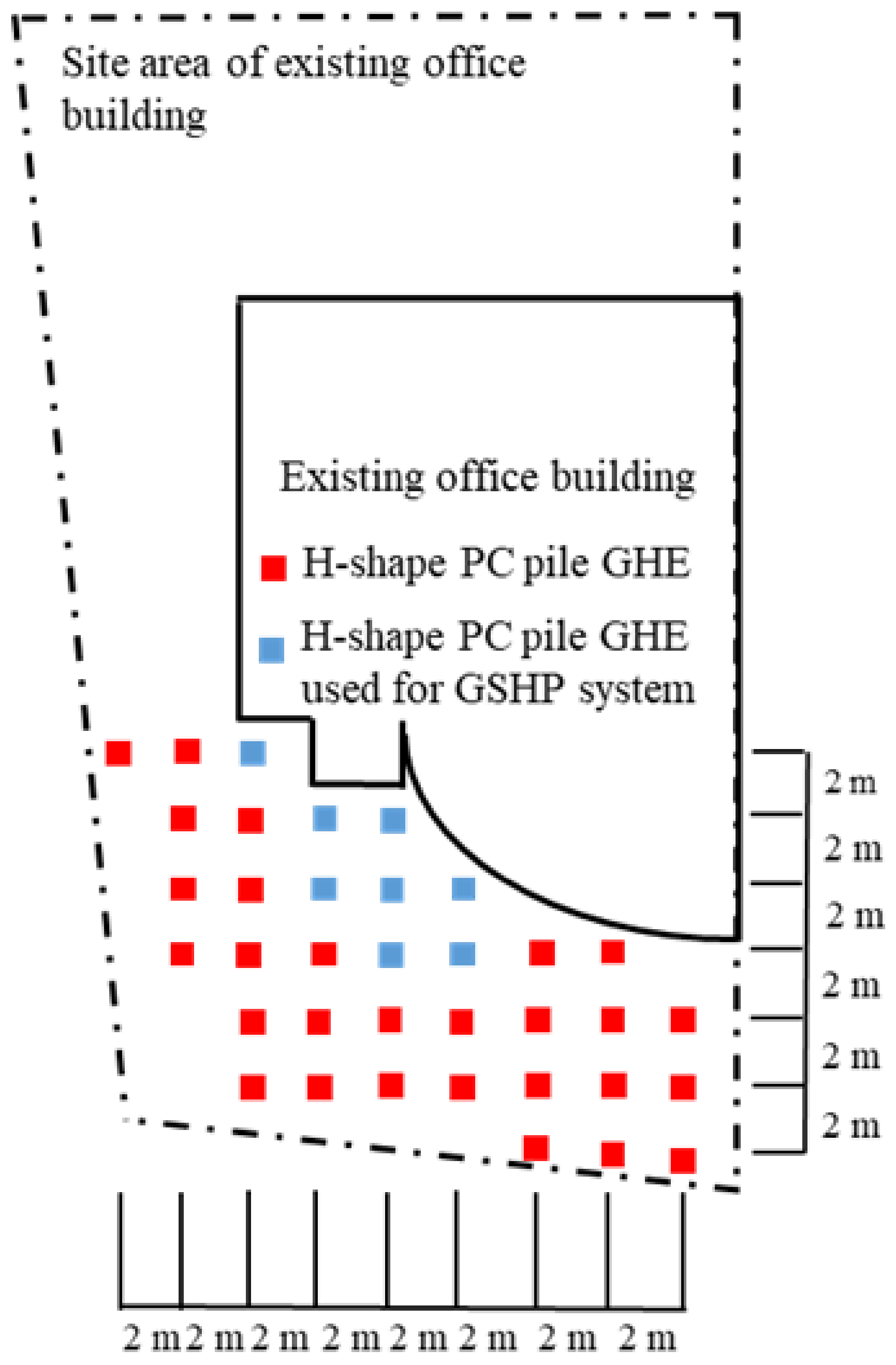
Figure 2. A site plan of the existing office building and the layout of GHEs.
Energies 17 00891 g002
The installation cost of H-shaped PC pile GHEs was estimated from the results. Furthermore, the installation cost of the H-shaped PC pile GHEs was compared with that of the conventional borehole GHE.

2.2. Evaluation of Ground Heat Exchanger Performance and Ground Source Heat Pump System via Actual Measurements

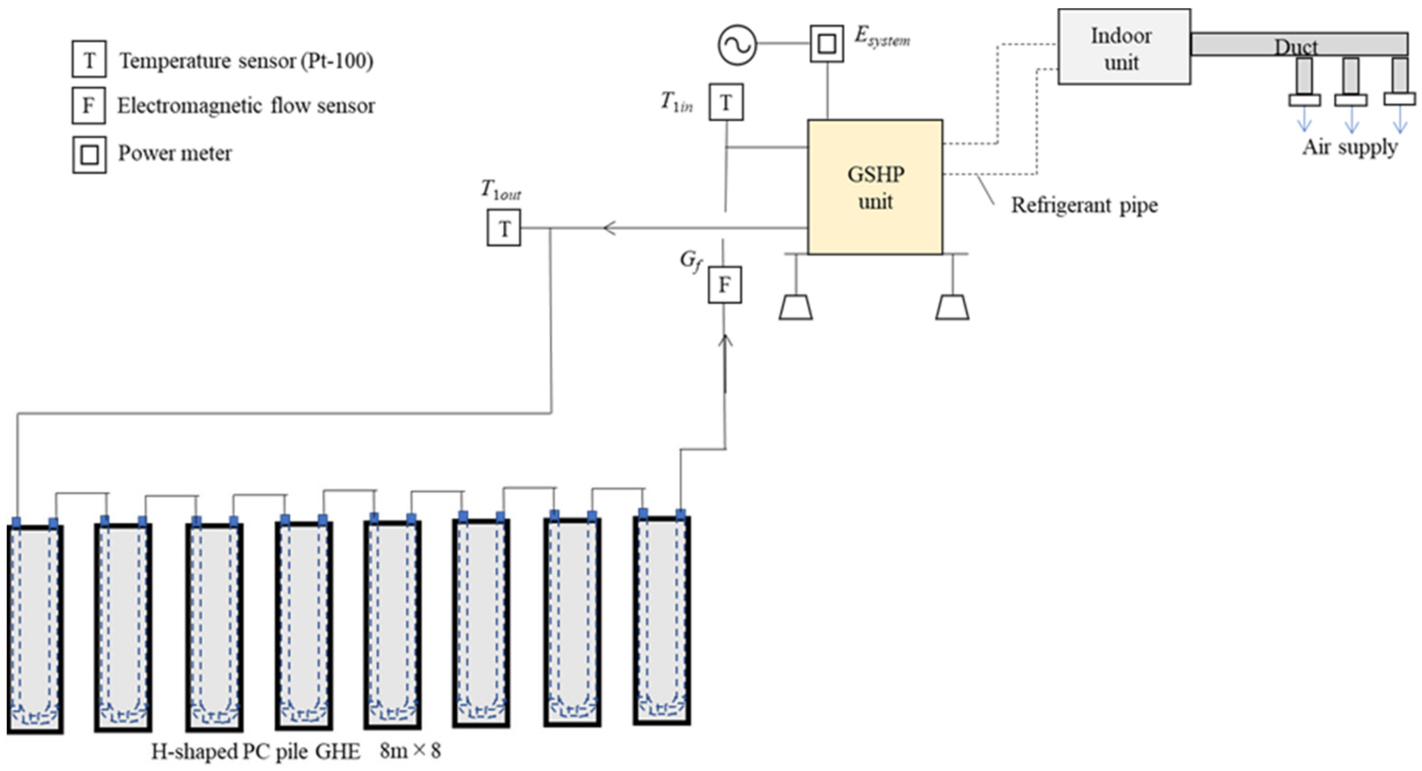
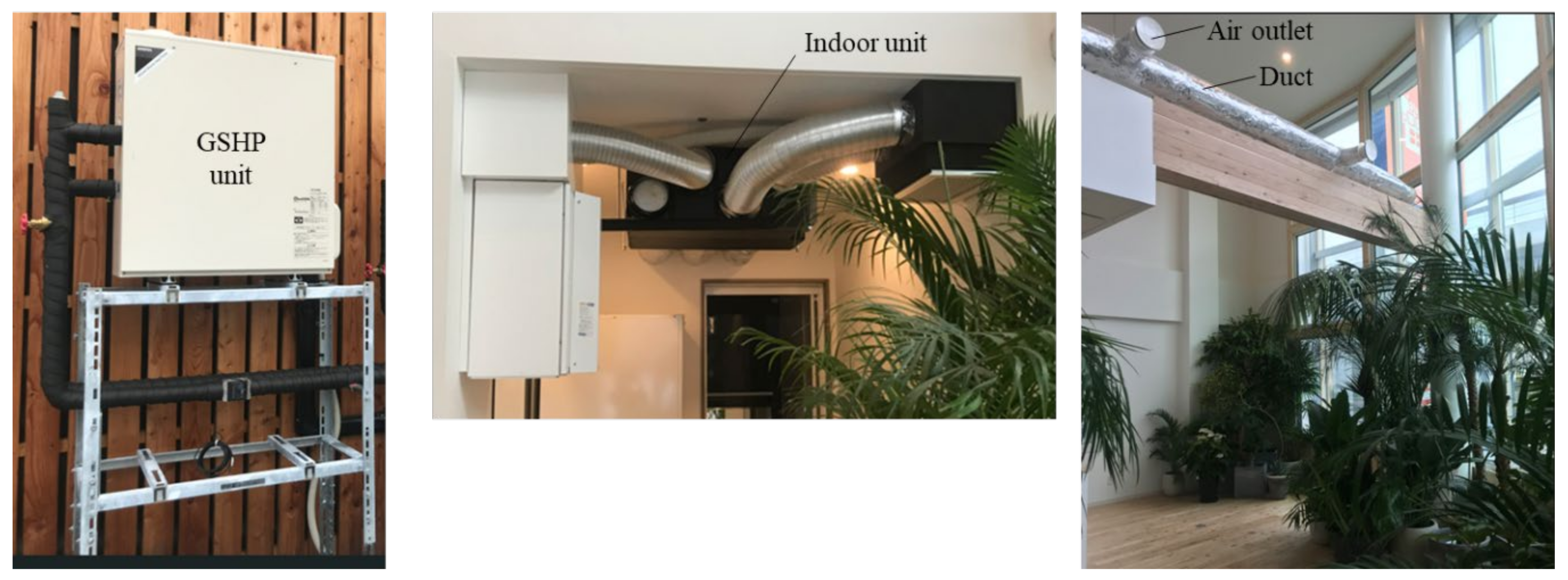
Figure 3 shows a diagram of the GSHP system with H-shaped PC-pile GHEs and the measurement points for the performance evaluation. In total, 8 of 36 H-shaped PC-pile GHEs installed in the existing office building were connected in series to each other and connected to the GSHP unit. Then, the GSHP system with GHEs and the GSHP unit was used for the heating and cooling of the 2nd floor of the existing office building. As shown in Figure 3, the temperature sensors were installed at the GHE’s inlet/outlet, and the electromagnetic flow sensor was installed. The power consumption of the GSHP unit with the built-in circulation pump and the indoor unit was also measured using a power meter. Table 1 indicates the experimentally measured parameters and their uncertainties. The performance of the GHEs and the GSHP unit was evaluated by measuring the temperature at the GHE’s inlet/outlet, the flow rate, and the power consumption during the GSHP system’s operation. Table 2 indicates the specifications of the GHE, GSHP unit, and circulation pump on the primary side, and Figure 4 shows the appearance of the GSHP unit, indoor unit, and the space to be air-conditioned. A GSHP unit air-conditioning system, which is relatively inexpensive and used as the central air-conditioning system in the residential house, is installed.
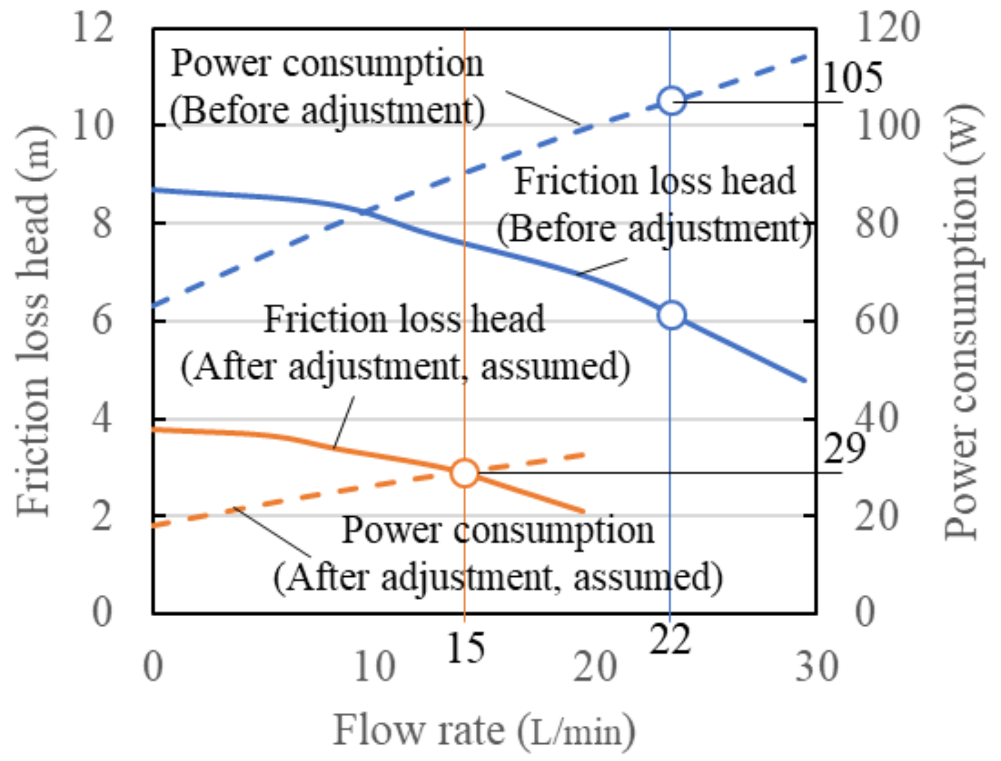
Figure 5 shows the conceptual diagram of a reduction in friction head loss and power consumption due to an adjustment in flow rate. The curves for friction head loss and power consumption before adjustments are values obtained from tests carried out at the factory and before shipment. The circulation flow rate and circulation pump power consumption were 22 L/min and 105 W, respectively, when the GSHP, circulation pump, and GHEs were connected in the field and the circulation pump was operated before the circulation pump was adjusted. These values were found to be consistent with the curves shown in Figure 5.
The built-in circulation pump can set flow rates with the controller and automatically adjust its speed to match the set flow rate. When the flow rate was set at 15 L/min, the power consumption of the pump was approximately 29 W. As the flow rate of the pump is proportional to the revolution speed, the friction head loss is proportional to the square of the revolution speed, and power consumption is proportional to the cube of the revolution speed. It is assumed that the curve of the friction head loss and power consumption changes as a result of the adjustment of the revolution speed. As a result, it can be assumed that power consumption has been reduced by adjusting the circulation pump.

3. Results

3.1. Installation Test and Installation Cost Estimation of H-Shaped PC Pile Ground Heat Exchangers

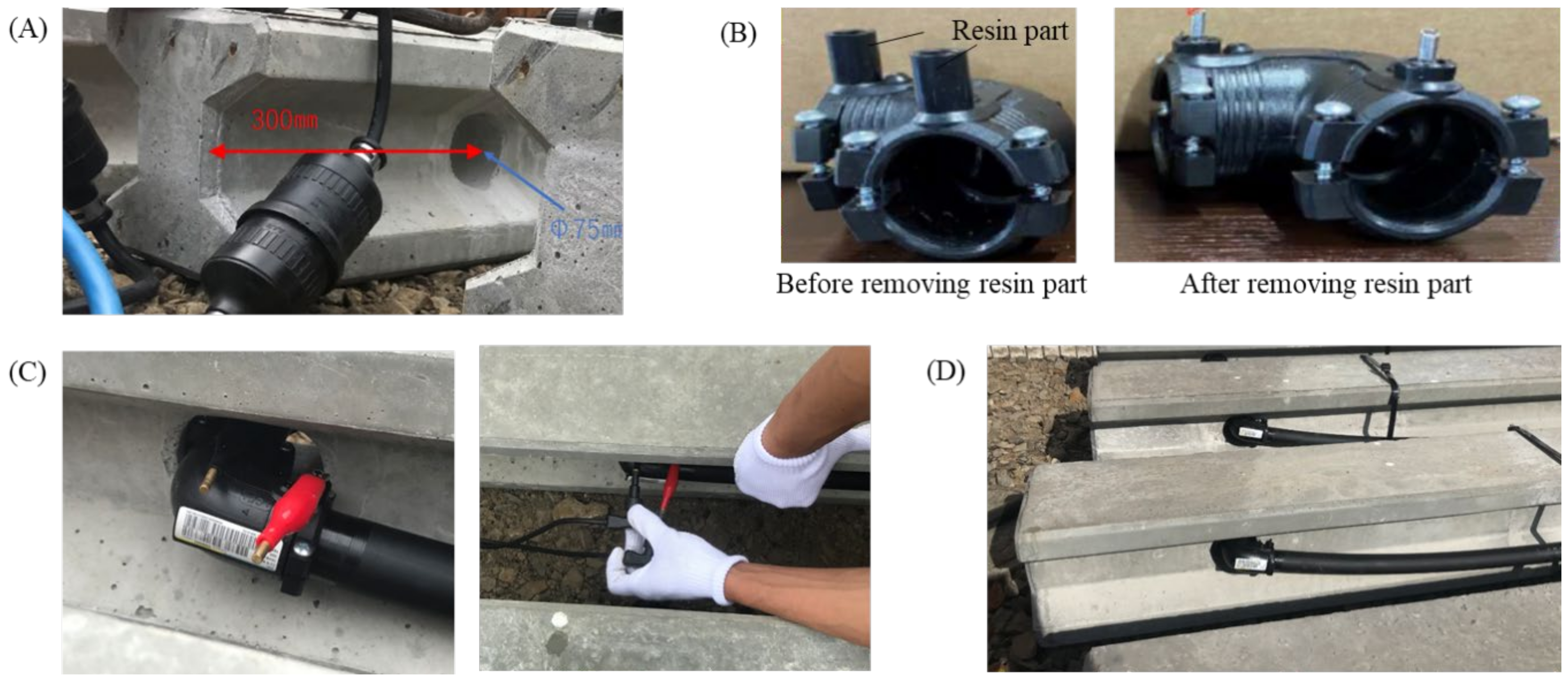
The H-shaped PC pile with a penetrating hole is shown in Figure 6A, and the procedure for installing U-tubes in the H-shaped PC pile is shown in Figure 6. The drilling of H-shaped PC piles for GHEs is carried out at the H-shaped PC pile factory. On the other hand, electrofusion work for installing the U-tube is carried out on-site. As shown in Figure 7, the pipe was passed through a hole in the H-shaped PC pile, and then the elbows were electrofused to form a U shape. If the terminal of the electrofusion was outside the through hole, the elbow part of the U-tubes would be outside the H-shaped PC pile, and the elbow part might be damaged when the H-shaped PC pile GHE was buried. Therefore, the diameter of the hole to be penetrated into the H-shaped PC pile was set to Φ75 mm, and as shown in Figure 6B, the resin part of the elbow’s current-carrying terminal was removed. As a result, the fusion splicer could be connected from the side of the current-carrying terminal of the elbow in the hole, as shown in Figure 6C. It was confirmed that this allowed the elbow portion of the GHE to be placed inside the H-shaped PC pile, as shown in Figure 6D. The installation of the U-tube in 36 H-shaped PC piles at the existing office took about 6 h, including the cutting of the piping and the processing of energized terminals. The H-shaped PC pile GHE was then installed (buried) at the existing office site, as shown in Figure 7. In this installation test, the gap between the H-shaped PC pile GHE and the borehole (annulus section) was backfilled with the residual soil generated during pre-boring. The time required for the pre-boring and installation of one H-shaped PC pile GHE was approximately 6 min, and it was confirmed that all 36 H-shaped PC pile GHEs could be installed within one day, including the delivery of the equipment. Although the time required may vary slightly depending on the ground conditions of the site, it was confirmed that the installation of GHE could be completed in less than half a day for one house (requiring 10 to 15 GHE piles).
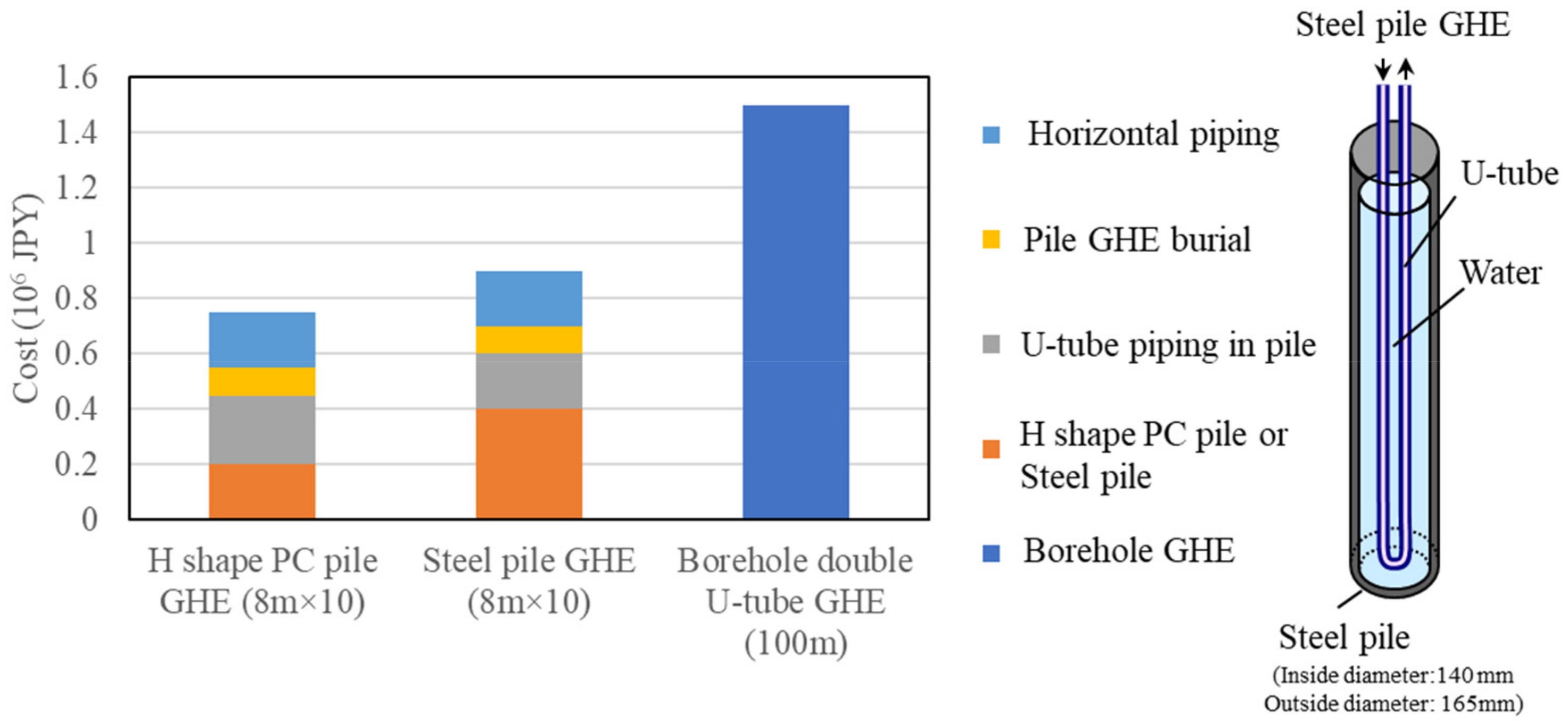
The results of the installation test are summarized, and the installation cost was estimated. Figure 8 shows the estimated cost of installing 8 m × 10 m H-shaped PC pile GHEs. The installation cost of conventional steel pile GHEs with a length and number of 8 m × 10 and a borehole GHE with a double U-tube and a length of 100 m is also shown in Figure 8 m. For H-shaped PC pile GHEs, the costs of burying H-shaped PC pile GHEs, connecting horizontal pipes, and installing U-tubes in H-shaped PC piles and H-shaped PC pile costs are included. By including all these costs, the GHE installation cost could be reduced to less than half compared to the conventional 100 m × 1 m borehole double U-tube type GHE. In comparison with steel pile GHEs, the cost of installing U-tubes is higher for H-shaped PC pile GHEs due to the need for on-site electrofusion. However, the overall cost of H-shaped PC pile GHEs is lower due to the lower cost of manufacturing the H-shaped PC piles.

3.2. Evaluation of Ground Heat Exchanger Performance and the Ground Source Heat Pump System via Actual Measurements

The GSHP system with H-shaped PC pile GHEs was operated from January 2021 to March 2022. The heat extraction and injection of GHE Q G H E (W) were calculated using the following equation based on the measured values of the GSHP inlet/outlet temperature and the flow rate.
Q G H E = c p f ρ f G f T 1 i n T 1 o u t
Here, we have the following definitions:
  • c p f : Specific heat capacity of fluid (kJ/(kg K));
  • ρ f : Density of fluid (kg/m3);
  • G f : Flow rate (m3/s);
  • T 1 i n ,   T 1 o u t : GSHP inlet and outlet temperature (K).
The heat extraction and injection of the GHE is equal to the heat extraction and injection of the GSHP’s primary side ( Q G H E   =   Q 1 ). The heating/cooling output Q 2 (W) from the GSHP is calculated from heat extraction and injection on the primary side Q 1 (W) and the power consumption of GSHP unit E h p (W) via the following equation.
Q 2 = Q 1 + E h p
Here, E h p = E s y s t e m E f a n E p u m p . E s y s t e m (W) is the power consumption of the GSHP unit with the built-in circulation pump and the indoor unit, and it is measured by a power meter. E f a n (W) is the power consumption of the fan of the indoor unit, and it is 240 W during operations. E p u m p (W) is the power consumption of the circulation pump, and it is 29 W during operations. During cooling operations, Q G H E and Q 2 become negative values.
The COP of the GSHP unit and the system COP (SCOP), including the circulation pump, are obtained via the following equation.
C O P = Q 2 / E h p
S C O P = Q 2 / ( E h p + E p u m p )
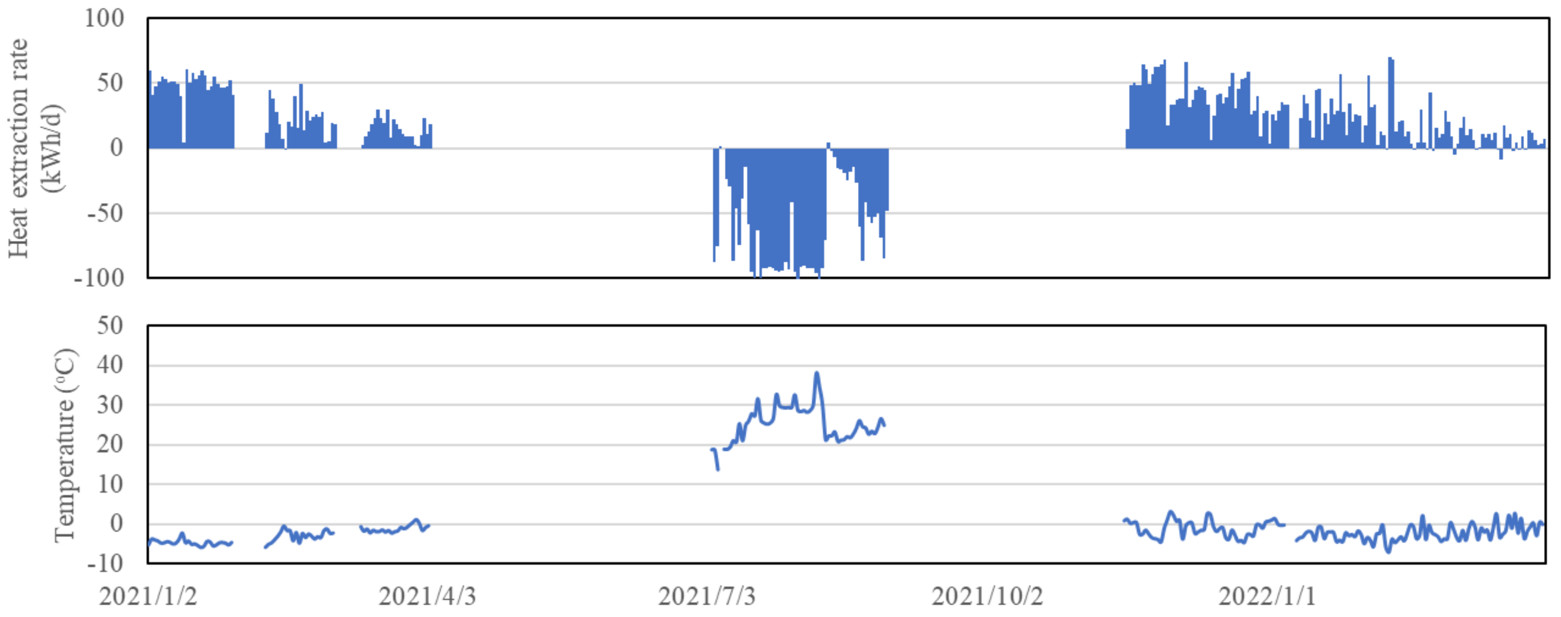
Figure 9 shows the daily changes in the heat extraction of GHEs and the average temperature of the heat carrier fluid: T f = T 1 i n + T 1 o u t / 2 . Here, the circulation flow rate of the GHE was almost constant at approximately 15 L/min throughout the period. The temperature of the heat carrier fluid remained between 0 °C and −5 °C in the winter, but in February 2022, there were two days of 70 kWh/d heat extraction, which caused medium heat temperatures to drop to approximately −7 °C. On the other hand, during the summer season, heat extraction continued to be around −90 kWh/d, and the temperature of the heat carrier fluid increased up to about 38 °C.
Figure 10 shows a plot of the relationship between the change in the temperature of heat carrier fluid T f from the undisturbed ground temperature T s 0 and the heat extraction per length of GHE ( q G H E (W/m)= Q G H E /(L × GHE Number), L × GHE Number = 8 m × 8 m = 64 m), assuming the undisturbed ground temperature as T s 0 = 11 °C. When the maximum and minimum temperature change points and the origin are connected, they are almost straight lines, confirming that there is no difference in the heat extraction and injection performance of GHE during the heating and cooling periods. In addition, the coefficients of heat extraction and injection q G H E (W/(m K)) are calculated using the following equation [13].
q G H E = q G H E / ( T s 0 T f )
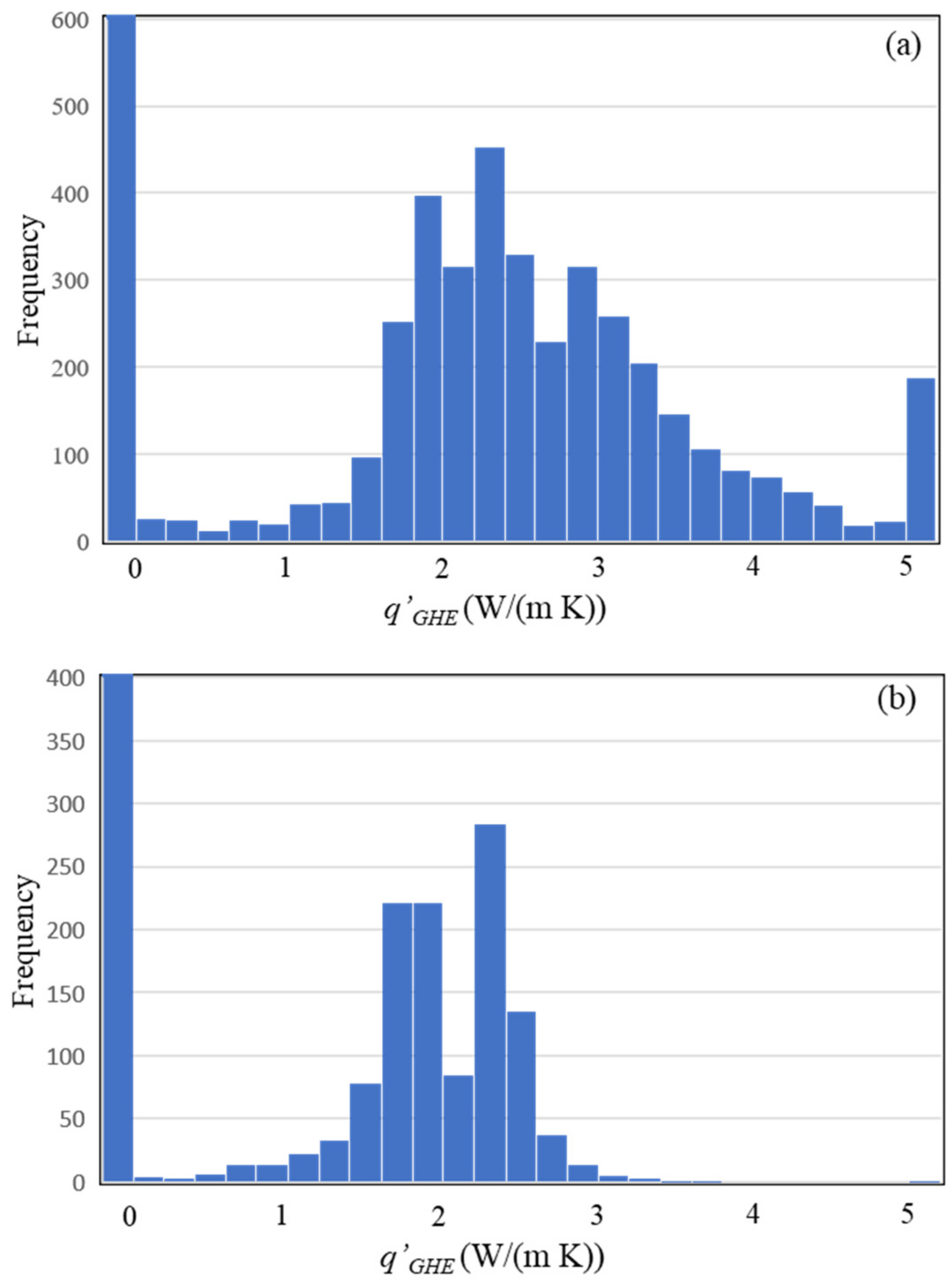
Based on the histograms of the calculated coefficient of heat extraction/injection for each hour, as shown in Figure 11a, frequency analyses revealed that the most frequently occurring approximate representation was within the range of 2.2–2.4 W/(m K). The value was slightly higher than that of the borehole single U-tube type GHE shown in the previous report [11]. This is thought to be a result of the following: The U-tubes in the H-shaped PC pile GHE are spaced more than 100 mm apart, as explained in the features section; furthermore, the thermal conductivity of the PC pile is low at 0.6 W/(m K), which suppresses the thermal interference of the U-tubes. In addition, if T s 0 T f is set to 15 °C, the heat extraction rate per the GHE’s length can be estimated as 33–36 W/m. Since the heat load is approximately 2.5 kW in midwinter and in a residential home with high thermal insulation specifications, as shown in [14], the required heat extraction is approximately 1.9 kW if the COP of the GSHP is set to 4. The required GHE length can be estimated as 58 m by dividing the required heat extraction by the heat extraction rate per the GHE’s length; thus, 8 m × 8 m GHEs are sufficient to provide the required heat extraction. In addition, Figure 11b shows the histogram of the coefficient of heat extraction/injection for January to April 2021, and Figure 11c shows the histogram of the coefficient of heat extraction/injection for November 2021 to March 2022. In Figure 11b, a frequency of 1.6 to 2.6 is high at about 800, and in Figure 11c, the frequency between 1.8 and 3.2 is high at about 1400. From these results, the range of high frequencies does not decrease from Figure 11b to Figure 11c, which suggests that there is no decrease in the coefficient of heat extraction/injection caused by a decrease in the ground temperature around the GHEs. In a previous report [7], a heating test using a GSHP system with 8 m × 25 m GHEs was conducted, but the heating load was assumed to be higher during lower insulation performances at that time, and the interference of the heat extraction of GHEs caused a long-term decrease in the ground temperature around GHEs.
However, under the present thermal load condition and GHE condition, no long-term ground temperatures occurred, and the results confirm that a GSHP system with 8 m × 8 m GHEs is sufficient for heating a residential house in the cold region if it has higher insulation performance.
The relationship between hourly heating outputs from the GSHP unit and SCOP is plotted in Figure 12. First, it can be observed that the SCOP for the heating output from the GSHP unit is relatively high, ranging from 3 to 6 when the heating output is 3 kW or lower, but when the heating output is 4 kW or higher, the SCOP is concentrated at values of 3 or lower. This indicates that this heat pump can achieve a high SCOP if it can be operated at a heating output of 3 kW or less. Table 3 summarizes the electric energy, heat extraction, heating output, and average SCOP during the heating period. The heating output in the heating period was approximately 5000 kWh, which is equivalent to the annual heating load of one residential house with high thermal insulation specifications [14]. This result confirms that this GSHP system is capable of continuous heating operations. The average SCOP during the heating period was 3.13, but since the heating operation in this building was intermittent, it was confirmed that an SCOP of 3.5 or higher could be expected if the system can be operated continuously and at a heating output of 3 kW or less. The energy consumption of circulation pumps in the winter season was 54 kWh. If the flow rate of the circulation pump is kept at 22 L/min before adjustments, energy consumption in the winter season is assumed to increase to approximately 190 kWh. As about three-quarters of the heating output of the GSHP is below 4 kW, the increase in the COP of the GSHP is expected to be small even if the circulation’s flow rate is increased. Regarding the SCOP and assuming a flow rate of 2.93 before adjustments, since an SCOP improvement of approximately 7% can be achieved, it can be said that the flow rate should be adjusted to 15 L/min when the GSHP system with H-shaped PC pile GHEs is installed in residential buildings.

4. Discussion

4.1. Comparison with Traditional Ground Source Heat Pump System

The GSHP system using H-shaped PC pile GHEs and the GSHP system using the conventional borehole GHE were first compared in terms of installation costs. As explained in Section 2.1, H-shaped PC pile GHEs can reduce the costs of GHE installation by half or more compared to the conventional 100 m × 1 m borehole double U-tube GHE. Furthermore, the GSHP air-conditioning system has less expensive secondary-side equipment than the conventional GSHP hot-water heating system, and installation costs can be reduced by more than 40% with respect to heat source equipment and secondary-side equipment.
Next, regarding the efficiency of the GSHP system, the SCOP of a conventional GSHP system in cold regions is about 3.5. As mentioned above, the SCOP of a GSHP system using H-shaped PC pile GHEs and a GSHP unit air-conditioning system is expected to be 3.5 or higher under continuous operation conditions.
Based on the above, if the ground conditions are such that H-shaped PC pile GHEs can be installed, there is a possibility of providing a GSHP system that can reduce the initial cost by 40% or more while maintaining the same efficiency compared to the conventional GSHP system.

4.2. Shortcomings of the Study

From the results of the installation test presented in this paper, it was confirmed that the process of installing H-shaped PC pile GHEs with U-tubes is the same as the process of normal H-shaped PC piles, and a significant initial cost reduction can be achieved compared to conventional borehole GHEs. On the other hand, the ground conditions at different sites are different, so it is necessary to determine whether or not H-shaped PC piles can be installed. Therefore, the following steps are necessary: verify the feasibility of the installation of H-shaped PC piles by interviewing H-shaped PC pile contractors to understand the ground conditions of each region from the ground information database, etc.; and indicate whether or not H-shaped PC pile GHEs can be installed at each location. The number of H-shaped PC pile GHEs required varies depending on the heat load conditions of the building, so it is important to indicate the number of H-shaped PC pile GHEs required for buildings with different areas, insulation specifications, and construction areas. Therefore, it is important to develop a design method and a design tool that can indicate whether or not H-shaped PC pile GHEs can be installed and the required number of H-shaped PC pile GHEs for each location.

5. Conclusions

In this paper, an H-shaped PC pile GHE that can be installed in small buildings and cold regions was developed, tested for installation, and evaluated in terms of costs. In addition, actual measurements during the heating and cooling operations of the GSHP system were conducted and evaluated, and the following findings were obtained:
  • The time required to install 36 H-shaped PC pile GHEs was one day. In addition, the cost required to install 10 m × 8 m piles per house was calculated and compared to the conventional 100 m × 1 m borehole double U-tube GHE, and it was confirmed that GHE installation costs could be reduced to less than half.
  • Based on the histograms of the calculated coefficient of heat extraction/injection for each hour, frequency analyses revealed that there was no increase in the coefficient of heat extraction/injection caused by a decrease in the ground temperature due to heat extraction.
  • The output for the heating period was approximately 5000 kWh, which is equivalent to the annual heating load of one residential house with high thermal insulation specifications. From these results, it was confirmed that this GSHP system is capable of continuous heating operations.
  • A GSHP system using H-shaped PC pile GHEs can reduce the total installation cost by 40% or more, including the GSHP unit and secondary-side equipment.

Author Contributions

Conceptualization, T.K. and K.S.; methodology, T.K., K.S. and M.O.; data curation, T.K., K.S. and M.O.; writing—original draft preparation, T.K.; writing—review and editing, T.K.; supervision, K.N.; funding acquisition, T.K., K.S. and M.O. All authors have read and agreed to the published version of the manuscript.

Funding

This research was funded by NEDO grant number P19006.

Data Availability Statement

The data presented in this study are available upon request from the corresponding author. The data are not publicly available because the original data volume is too large and complex, making it difficult to understand.

Acknowledgments

This study is based on results obtained from the project “Renewable energy heat utilization technology development for cost reduction,” commissioned by the Japan National agency New Energy and Industrial Technology Development Organization (NEDO). Also, the authors would like to express appreciation to AIZAWA Concrete Corporation, Motohiro Maeda, Kohei Nimura, and Chen Daoxuan for supporting this research work.

Conflicts of Interest

Author Katsuya Saito was employed by the company Ambiente Innovation Co., Ltd.; and author Motoaki Oe was employed by the company INOAC Housing & Construction Materials Co., Ltd. The remaining authors declare no conflict of interest. The funders had no role in the design of the study; in the collection, analyses, or interpretation of data; in the writing of the manuscript; or in the decision to publish the results.

Nomenclature

Symbols
cspecific heat capacity, J/(kg∙K)
Eelectric power consumption, W
Gflow rate, m3/s
Llength/depth, m
Qheating/cooling output, heat extraction/injection, W
qheat extraction/injection per length, W/m
q’coefficient of heat extraction/injection,
W/(m∙K)
Ttemperature, ℃
ρdensity, kg/m3
Subscripts
1primary side
2secondary side
fcirculating fluid
fanfan
GHEground heat exchanger
hpheat pump
ininlet
outoutlet
pumpcirculation pump
s0undisturbed soil
systemsystem
Abbreviations
COPcoefficient of performance
GHEground heat exchanger
GSHPground source heat pump
HVACheating, ventilation, and air conditioning
SCOPsystem coefficient of performance

References

  1. Lund, J.W.; Toth, A.N. Direct utilization of geothermal energy 2020 worldwide review. Geothermics 2021, 90, 101915. [Google Scholar] [CrossRef]
  2. Zarrella, A.; Capozza, A.; Carli, M.D. Analysis of short helical and double U-tube borehole heat exchangers: A simulation-based comparison. Appl. Energy 2013, 112, 358–370. [Google Scholar] [CrossRef]
  3. Zarrella, A.; Emmi, G.; Carli, M.D. Analysis of operating modes of a ground source heat pump with short helical heat exchangers. Energy Convers. Manag. 2015, 97, 351–361. [Google Scholar] [CrossRef]
  4. Kim, J.; Nam, Y. Development of the Performance Prediction Equation for a Modular Ground Heat Exchanger. Energies 2020, 13, 605. [Google Scholar] [CrossRef]
  5. Kim, K.; Kim, J.; Nam, Y.; Lee, E.; Kang, E.; Entchev, E. Analysis of Heat Exchanger Rate for Low-Depth Modular Ground Heat Exchanger through Real-Scale Experiment. Energies 2021, 14, 1893. [Google Scholar] [CrossRef]
  6. Kim, K.; Bae, S.; Nam, Y.; Lee, E.; Kang, E.; Entchev, E. Development of a Low-Depth Modular GHX through a Real-Scale Experiment. Energies 2022, 15, 698. [Google Scholar] [CrossRef]
  7. Katsura, T.; Nagano, K.; Narita, S.; Takeda, S.; Nakamura, Y.; Okamoto, A. Calculation Algorithm of the Temperatures for Pipe Arrangement of Multiple Ground Heat Exchangers. Appl. Therm. Eng. 2009, 28, 906–919. [Google Scholar] [CrossRef]
  8. Katsura, T.; Higashitani, T.; Fang, Y.; Sakata, Y.; Nagano, K.; Akai, H.; Oe, M. A New Simulation Model for Vertical Spiral Ground Heat Exchangers Combining Cylindrical Source Model and Capacity Resistance Model. Energies 2020, 13, 1339. [Google Scholar] [CrossRef]
  9. Fujii, H.; Nighi, K.; Komaniwa, Y.; Chou, N. Numerical modeling of slinky-coil horizontal ground heat exchangers. Geothermics 2012, 41, 55–62. [Google Scholar] [CrossRef]
  10. Fujii, H.; Yamasaki, Y.; Maehara, T.; Ishikami, T.; Chou, N. Numerical simulation and sensitivity study of double-layer Slinky-coil horizontal ground heat exchangers. Geothermics 2013, 47, 61–68. [Google Scholar] [CrossRef]
  11. Jalaluddin; Miyara, A. Thermal performance investigation of several types of vertical ground heat exchangers with different operation mode. Appl. Therm. Eng. 2012, 33–34, 167–174. [Google Scholar] [CrossRef]
  12. Japan Meteorological Agency. Weather Data in Sapporo in 2021. Available online: https://www.data.jma.go.jp/stats/etrn/view/monthly_s1.php?prec_no=14&block_no=47412&year=2021&month=&day=&view= (accessed on 4 January 2024). (In Japanese).
  13. Yang, K.; Katsura, T.; Nagasaka, S.; Nagano, K. Analyzing the Performance of Double Spiral Tube Ground Heat Exchangers in a Zero-Energy Building Using Measurement Data. Energies 2023, 13, 1339. [Google Scholar] [CrossRef]
  14. Katsura, T.; Ohara, T.; Kamada, T.; Nagano, K.; Memon, S. Analysis of indoor environment and insulation performance of residential house with double envelope vacuum insulation panels. Int. J. Solar Therm. Vacuum Eng. 2021, 3, 1–14. [Google Scholar] [CrossRef]
Figure 1. Appearance of H-shaped PC pile GHEs (a): vertical section (b); horizontal section (c).
Energies 17 00891 g001
Figure 3. A diagram of the GSHP system with H-shaped PC-pile GHEs and the measurement points.
Energies 17 00891 g003
Figure 4. Appearance of the GSHP unit, indoor unit, and the space to be air-conditioned.
Energies 17 00891 g004
Figure 5. Conceptual diagram of a reduction in friction head loss and power consumption via adjustments to the flow rate.
Energies 17 00891 g005
Figure 6. Proceedings of the installation of the U-tube in the H-shaped PC pile. (A) H-shaped PC pile with penetrating hole. (B) Removing the resin part from the elbow’s current-carrying terminal. (C) Connecting the fusion splicer to the current-carrying terminal of the elbow. (D) H-shaped PC pile GHE with U-tube.
Energies 17 00891 g006
Figure 7. Pre-boring (left) and installing the H-shaped PC pile GHE into the ground (right).
Energies 17 00891 g007
Figure 8. Comparison of the installation cost of the H-shaped PC pile GHE, the conventional steel pile GHE, and the conventional borehole double U-tube GHE.
Energies 17 00891 g008
Figure 9. Variations in the heat extraction of GHEs and the average temperature of heat carrier fluid.
Energies 17 00891 g009
Figure 10. A relationship between the change in the temperature of heat carrier fluid from the undisturbed ground temperature and the heat extraction per length of GHE.
Energies 17 00891 g010
Figure 11. Histograms of the calculated coefficient of heat extraction/injection for each hour. (a) Whole period; (b) from January 2021 to April 2021; (c) from November 2021 to March 2022.
Energies 17 00891 g011aEnergies 17 00891 g011b
Figure 12. A relationship between the hourly heating output of the GSHP unit and SCOP.
Energies 17 00891 g012
Table 1. Experimental uncertainty.
ParameterValueUncertainty
T1out°C ( 0.30 + 0.005 T )
T1in°C ( 0.30 + 0.005 T )
GfL/min0.005Gf
EsystemkWh0.012Esystem
Table 2. Specification of the GHE, GSHP, circulation pump, and antifreeze solution.
GHETypeH-shaped PC pile GHE
Borehole length × number8 m × 8 m
Borehole diameter0.3 m
Pipe outside diameter0.032 m
Pipe inside diameter0.026 m
GSHP unitTypeGSHP air-conditioning system
Rated heating/cooling output6.0 kW/6.3 kW
Rated electric power for heating/cooling1.72 kW/1.43 kW
Circulation pump in the primary sideFlow rate (before adjustment/after adjustment)22/15 L/min
Electric power (before adjustment/after adjustment)0.105/0.029 kW
Antifreeze solution (on the primary side)Ethylene glycol 40%
Table 3. Electric energy, heat extraction, heating output, and average SCOP during the heating period.
PeriodΣ Ehp
(kWh)
Σ Epump
(kWh)
Heat Extraction (kWh)Heating Output (kWh)Average SCOP
November 2021~April 2022156154345350203.13
Disclaimer/Publisher’s Note: The statements, opinions and data contained in all publications are solely those of the individual author(s) and contributor(s) and not of MDPI and/or the editor(s). MDPI and/or the editor(s) disclaim responsibility for any injury to people or property resulting from any ideas, methods, instructions or products referred to in the content.