Abstract
Parity-time (PT) symmetry has made encouraging progress in wireless power transmission (WPT), exhibiting significant advantages in terms of system robustness and transmission efficiency. However, there are still challenges that need to be addressed, particularly when classical schemes operate at a fixed frequency in the weak coupling region, where even minor changes in coupling strength can result in excessive current surges. This paper introduced a novel PT-symmetric WPT system featuring negative resistance constructed on the receiver side. We first established a theoretical framework for the classical two-coil PT-symmetric magnetically coupled resonant WPT system and subsequently extended it to incorporate the PT-symmetric WPT system with negative resistance on the receiver. This topological coil configuration facilitated stable power delivery over a broader range, with the capability of self-tuning frequency without requiring additional frequency modulation. This adaptability enabled the system to cater to diverse scenarios and opens up a novel avenue for practical applications of PT symmetry in WPT. Finally, we designed a 10 W prototype to demonstrate the effectiveness of our topology, and the experimental results aligned with our theoretical calculations, validating the feasibility and potential of our PT-symmetric WPT system.
1. Introduction
Wireless power transmission (WPT) is a technology that enables the transmission of electrical power through space without the need for physical connections. It boasts portability, flexibility, intelligence, and many other characteristics and is widely applied in various scenarios, such as electric vehicles, mobile terminals, and implantable medical devices [1,2]. Recently, non-Hermitian systems in condensed matter physics [3,4,5], particularly those exhibiting parity-time (PT) symmetry with real eigenvalues, have made theoretical breakthroughs to magnetically coupled resonant WPT [6,7,8,9].
Scholars such as Assawaworrarit from Stanford University proposed a PT-symmetric WPT working mode [10,11]. They constructed gain through the nonlinear saturation characteristics of operational amplifiers to meet loss [12]. The experimental results showed that this PT-based WPT system can achieve constant output power and extremely high and stable transfer efficiency within the transmission distance of 20–70 cm. In subsequent research, they proposed introducing a bridge inverter circuit into the negative resistance design [13], which enhanced the overall system efficiency, avoided the loss of the operational amplifier itself, and also increased the output power. When the PT-symmetric conditions were satisfied, previous studies showed that the transfer efficiency remained near unity over a distance variation in approximately one meter, without the need for any tuning [10,14]. On the other hand, due to the variable gain provided by the inverter, the system can still track the loss changes in the broken phase, which still provides high transfer efficiency for the system. This achievement has garnered widespread attention; to further enhance the output power and expand the range of PT symmetry region, some scholars have taken additional measures such as increasing additional components, altering the shape or placement of coils to achieve an increase in the range of strong coupling region [15,16,17,18]. By introducing multi-coil topologies into the load end, they have managed to elevate the system’s output power [9,19,20]. Furthermore, through the calculation of higher-order PT symmetric dynamic equations, various operational modes have been proposed [21,22,23].
However, there remains the issue of excessively high current in the system when the coils are weakly coupled. Short-range changes in the coupling coefficient may result in significant power surges [24], which are not conducive to stable energy supply. The instantaneous change in current may cause the equipment to overload, resulting in equipment burnout, circuit board damage, or other component damage, seriously affecting the service life of the equipment [25]. To address these issues, based on the experience and methods of constructing PT-symmetric WPT working modes, this paper proposed a method of extracting current phase at the receiver to provide gain. Compared with the classical PT-symmetric WPT, our method can solve the problem.
The main aim of this paper was to extend the mathematical model of classical PT-symmetric WPT to a scheme based on receiver current providing gain. This method avoids excessive current surges while maintaining high transfer efficiency. It retains the advantages of the PT-symmetric WPT model, such as the ability to self adjust frequency, stable power supply, and fewer additional control components. In Section 2, the proposed WPT system model was established based on the analysis of conventional schemes. Characteristics including operating frequency, output power, and transmission efficiency were analyzed. In Section 3, a 10 W prototype was implemented and tested to validate the effectiveness of the theoretical analysis presented in Section 2. This model reduced the primary current of traditional models by nearly 50% when the coupling coefficient k = 0.102, avoiding the impact of high currents on the circuit. Finally, the conclusions were drawn in Section 4.
2. Modeling of PT-Symmetric WPT System
2.1. PT-Symmetric WPT Model
Generally, the time evolution of the amplitude in the resonant cavity of the transmitter and receiver in a standard PT-symmetric dimer can be presented as follows [10]:
where and are the resonant frequencies of the transmitter and receiver; and denote gain and loss; is the coupling rate between the resonators. The energy modes and are designated in such a way that the energy contained within the transmitter and receiver resonators corresponds to and , respectively.
According to Assawaworrarit et al. [10], when conditions , and are met, the characteristic equation is solved to yield the following PT-symmetric solutions:
- 1.
- When ,
- 2.
- When ,
Figure 1 introduces the classical series–series topology PT-symmetric WPT, where the gain design is realized in the form of an inverter implementing a negative resistance, as shown in Figure 2a. When the PT-symmetric conditions are satisfied, the relationship between voltage and current in the transmitter circuit is depicted in Figure 2b, while the output voltage of the inverter can be expressed by Equation (4).
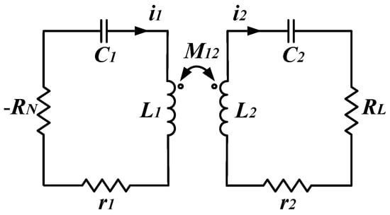
Figure 1.
Equivalent circuit diagram of a PT-symmetric MC-WPT system employing a series–series topology incorporating nonlinear negative resistance.
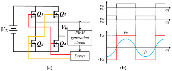
Figure 2.
(a) Schematic of nonlinear negative resistor. (b) The voltage of in the steady state.
Applying Kirchhoff’s voltage law in classical electric circuit theory (ETC), we obtain the following:
where and , is the operating frequency, and . For simplicity, we can assume and in the given circuit. Based on the experience of calculating the characteristic frequencies in PT-symmetric WPT, we compared Equation (5) with Equation (1) and directly calculated the determinant value of Equation (5). By separating the real and imaginary parts of the determinant value in Equation (5), we can obtain the following:
To meet real eigenvalues, the system must adhere to either or . The three solutions of Equation (6) are as follows:
- 1.
- When
- 2.
- When
When , the equivalent input impedance as shown in Figure 1 is
If the system always satisfies Equation (9), then the system achieves ZPA [26]. Substitute and divide Equation (8) by to obtain a quadratic equation about
In this case, the operating points for efficient transmission of the system are located at the solutions of the quadratic function. It can be deduced that , considering is predesigned, the existence of two different solutions is ensured as long as . In addition, the critical coupling coefficient is obtained by setting . Therefore, three modes could exist, with eigenfrequencies the can be read as follows:
Hence, we obtained the same results as ECT through straightforward calculations, while avoiding the two simplifications previously made in deriving the CMT model from ECT: neglecting the influence of higher-order frequencies and the impact of the coupling coefficient in the weak coupling region [27].
Based on Equation (8), we can obtain the square ratio of the current at the transmitter and receiver. Furthermore, the transfer efficiency has been analyzed comprehensively in both areas:
where and are, respectively, the effective values of the currents in the transmitting coil and the receiving coil. It can be seen that the relationship between the transmission efficiency of the system and the coil coupling coefficient varies between different coupling regions, where . Similarly, using Equation (9), the output power of the system is calculated as follows:
From Equations (13) and (14), when , both the power delivered to the load () and the transmission efficiency () are independent of the coupling coefficient (k). Consequently, the output power () and the transmission efficiency () remain constant. In contrast, when , the power and transmission efficiency are consistently influenced by variations in the coupling coefficient.
2.2. The Receiver-Based PT-Symmetric WPT Model
The classic nonlinear PT symmetric model drives the full bridge circuit through the phase information of the primary current, so it can autonomously adjust the frequency. Obtaining phase information at the load end still has this characteristic.
Considering the impact of PT symmetry at the receiver on the system, this paper constructed a PT-symmetric WPT model based on the load end, as shown in Figure 3. From the Equation (5), there is always a phase difference between and , which leads to Equation (15) for . By substituting for in Equation (5) and subsequently computing the determinant, we can derive the relationship pertaining to as follows:
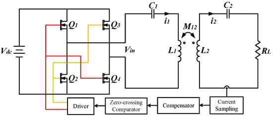
Figure 3.
Receiver-based PT-symmetric WPT system.
Taking to be real, the strength of corresponds to a steady-state solution. As can be seen from Figure 4, the gain can be obtained by changing the magnitude of the current. When , , , and , Equation (16) can be transformed into a quadratic equation with respect to the normalized eigenfrequencies as follows:
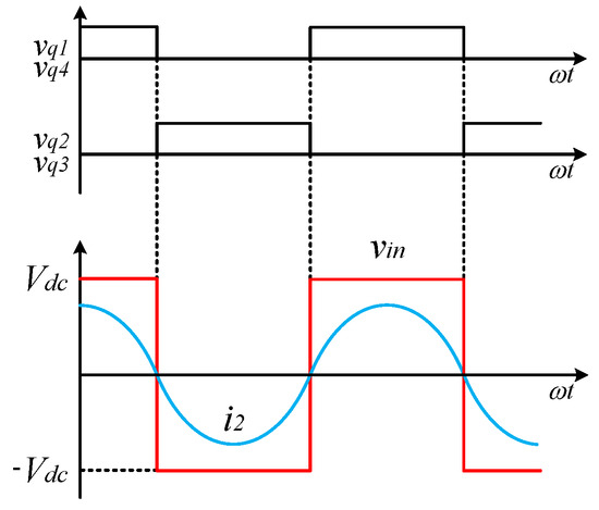
Figure 4.
The voltage of in the steady state.
In Equation (18), it is always true that . Consequently, in quadratic functions, we can conclude that . Compared to the classical PT-symmetric WPT, the operating frequency of this topology does not directly contact but rather approaches the exceptional point (EP). According to Equation (16), the square ratio of the current can be expressed as follows:
Let us define the loss as , and represents the steady angular frequency. Within the steady-state frequency variation range, the loss variable exhibits small deviation from its fixed counterpart , maintaining a consistently low value. Consequently, in the context of (13), the power transfer efficiency can be accurately characterized as follows:
Similarly, the output power is estimated by the following:
Here, it can be inferred that the output power is solely proportional to the coupling coefficient, and the decline rate is not rapid.
3. Experimental Verification
The proposed PT-symmetric wireless power transmission device was constructed experimentally. In order to merely verify the effectiveness of this scheme, this device does not have an additional DC/DC converter to provide a stable voltage and current for the load. Figure 5a and Table 1 present all components and their respective electrical parameters. In the experimental prototype, the full bridge inverter is constructed based on DRV8701E. The use of TPH1R403NL transistors can operate at high frequencies with low power consumption and switching losses, further improving the overall system efficiency.
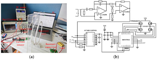
Figure 5.
(a) Experimental prototype of the WPT. (b) Control circuitry in the experimental prototype.

Table 1.
Experimental circuit parameters.
Throughout the entire control process depicted in Figure 5b, once the current phase sensor detects a zero-crossing point, it outputs a square wave phase signal. This signal then passes through an SN74HC125 buffer, which drives the DRV8701E chip to generate driving signals that control the H-bridge. Ultimately, the full-bridge circuit regulates the power supply voltage and outputs it to the resonant tank. The experiment uses the same acrylic board and coil to move parallel to the edge of the ruler while avoiding sudden changes in coupling coefficient and equivalent resistance [28,29] as much as possible.
Before the experiment, we measured the induced electromotive force at different distances to obtain the mutual inductance M between the two coils and then calculated the coil mutual inductance coefficient using formula . Figure 6 shows the variation in coupling coefficient as a function of the center-to-center distance between the coils.
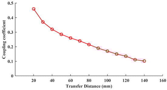
Figure 6.
Measured results of coupling coefficient versus center-to-center distance between coils.
In the data calculation of this experiment, considering ideal conditions, including coils being parallel and center to center, there may be some errors in the calculation results. Even if the experiment uses parallel acrylic sheets and coils that are as similar as possible to move parallel to the edge of the ruler, the displacement of the coils can cause sudden changes in coupling coefficients, equivalent resistance changes, and other experimental effects. In the scheme proposed in this article, we have chosen the part with lower operating frequency. Comparing these two topologies within a measurement transmission distance of 20–140 mm corresponds to the constant power transmission capability of the proposed system. According to Figure 6, considering the experimental results obtained, it can be concluded that the strong coupling region of the system is approximately within the range of 20–70 mm, while it operates in the weak coupling region within the range of 70–140 mm.
In the strong coupling region, as the transfer distance decreases, the operational frequency of our topology approaches closely to the classic PT-symmetric WPT depicted in Figure 7a. As the system nears the exceptional point where PT symmetry is broken, the operating frequency gradually approaches the natural operational frequency of the system. Throughout the entire range of the transfer distance, there is no need for active frequency modulation, and the experimental results for the operational frequency align with theoretical calculations. Figure 7b,c depict the current in primary coil and the output power of the loads in two topological systems. Within the weakly coupled regime of the conventional PT-symmetric WPT, the load power exhibited a surge, which was not only detrimental to efficient power supply but also poses a risk of electrical surge damage to the circuitry itself. However, our improved scheme exhibited a more gradual variation in power and effectively enlarged the range of stable load power compared to the traditional PT-symmetric strong coupling region. Compared to traditional solutions, in the platform we built, at the weak coupling operating point k = 0.102, the primary current decreased by nearly 50%. The analysis of experimental results showed that compared with traditional schemes, the transmission efficiency has decreased by 2–8% with the variation in transmission distance after calculation.
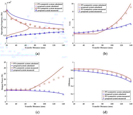
Figure 7.
(a) Comparison of operating frequencies using coupling coefficient as a function. (b) Comparison of primary coil current. (c) Comparison of output power based on . (d) Comparison of the efficiency of stable working states between two topological systems.
4. Conclusions
The PT-symmetric WPT based on receiver-side gain design proposed in this paper boasted nearly efficient transmission efficiency compared to traditional schemes, while eliminating the need for active tuning. It effectively mitigated excessive power fluctuations in the weakly coupled region, thereby extending the range of stable power output. Furthermore, we constructed experimental prototypes for two distinct PT-symmetric WPT system topologies using identical parameters, and the experimental results validated the effectiveness of the proposed method. In practical applications, the use of receiver-based PT-symmetric WPT resulted in a lower output power in the weakly coupled region compared to traditional methods, reducing the risk of overvoltage and overcurrent in the equipment. Although tracking the current phase on the receiver was not inherently advantageous for wireless power transfer, our work retained significant importance for electronic devices that necessitate continuous wireless information transmission between the receiver and transmitter.
Author Contributions
Conceptualization, X.Y.; Data curation, X.Y. and W.Y.; Methodology, X.Y.; Writing—original draft, X.Y. and W.Y.; Writing—review and editing, X.Y. and W.Y. All authors have read and agreed to the published version of the manuscript.
Funding
This research received no external funding.
Data Availability Statement
The original contributions presented in the study are included in the article, further inquiries can be directed to the corresponding author.
Conflicts of Interest
The authors declare no conflicts of interest.
References
- Lan, Y.; Jiang, J.; Yang, F.; Song, K.; Fan, F.; Sun, C.; Yang, G.; Zhang, B.; Lan, H. Research on Impedance Boundary and Tolerance Zone for Improving Wireless Charging Interoperability Evaluation of Electric Vehicles. IEEE Trans. Power Electron. 2024, 39, 12035–12040. [Google Scholar] [CrossRef]
- Pahlavan, S.; Shooshtari, M.; Jafarabadi Ashtiani, S. Star-Shaped Coils in the Transmitter Array for Receiver Rotation Tolerance in Free-Moving Wireless Power Transfer Applications. Energies 2022, 15, 8643. [Google Scholar] [CrossRef]
- Rüter, C.E.; Makris, K.G.; El-Ganainy, R.; Christodoulides, D.N.; Segev, M.; Kip, D. Observation of Parity–Time Symmetry in Optics. Nat. Phys. 2010, 6, 192–195. [Google Scholar] [CrossRef]
- Bender, C.M.; Boettcher, S. Real Spectra in Non-Hermitian Hamiltonians Having PT Symmetry. Phys. Rev. Lett. 1998, 80, 5243–5246. [Google Scholar] [CrossRef]
- El-Ganainy, R.; Makris, K.G.; Khajavikhan, M.; Musslimani, Z.H.; Rotter, S.; Christodoulides, D.N. Non-Hermitian Physics and PT Symmetry. Nat. Phys. 2018, 14, 11–19. [Google Scholar] [CrossRef]
- Krasnok, A.; Baranov, D.G.; Generalov, A.; Li, S.; Alù, A. Coherently Enhanced Wireless Power Transfer. Phys. Rev. Lett. 2018, 120, 143901. [Google Scholar] [CrossRef]
- Zhang, H.; Zhu, K.; Guo, Z.; Chen, Y.; Sun, Y.; Jiang, J.; Li, Y.; Yu, Z.; Chen, H. Robustness of Wireless Power Transfer Systems with Parity-Time Symmetry and Asymmetry. Energies 2023, 16, 4605. [Google Scholar] [CrossRef]
- Xie, Y.; Zhang, Z.; Lin, Y.; Feng, T.; Xu, Y. Magnetic Quasi-Bound State in the Continuum for Wireless Power Transfer. Phys. Rev. Appl. 2021, 15, 044024. [Google Scholar] [CrossRef]
- Zeng, C.; Guo, Z.; Zhu, K.; Fan, C.; Li, G.; Jiang, J.; Li, Y.; Jiang, H.; Yang, Y.; Sun, Y.; et al. Efficient and Stable Wireless Power Transfer Based on the Non-Hermitian Physics. Chin. Phys. B 2022, 31, 010307. [Google Scholar] [CrossRef]
- Assawaworrarit, S.; Yu, X.; Fan, S. Robust Wireless Power Transfer Using a Nonlinear Parity–Time-Symmetric Circuit. Nature 2017, 546, 387–390. [Google Scholar] [CrossRef]
- Ra’Di, Y.; Chowkwale, B.; Valagiannopoulos, C.; Liu, F.; Alu, A.; Simovski, C.R.; Tretyakov, S.A. On-Site Wireless Power Generation. IEEE Trans. Antennas Propag. 2018, 66, 4260–4268. [Google Scholar] [CrossRef]
- Schindler, J.; Lin, Z.; Lee, J.M.; Ramezani, H.; Ellis, F.M.; Kottos, T. PT-Symmetric Electronics. J. Phys. A Math. Theor. 2012, 45, 444029. [Google Scholar] [CrossRef]
- Zhou, J.; Zhang, B.; Xiao, W.; Qiu, D.; Chen, Y. Nonlinear Parity-Time-Symmetric Model for Constant Efficiency Wireless Power Transfer: Application to a Drone-in-Flight Wireless Charging Platform. IEEE Trans. Ind. Electron. 2019, 66, 4097–4107. [Google Scholar] [CrossRef]
- Assawaworrarit, S.; Fan, S. Robust and Efficient Wireless Power Transfer Using a Switch-Mode Implementation of a Nonlinear Parity–Time Symmetric Circuit. Nat. Electron. 2020, 3, 273–279. [Google Scholar] [CrossRef]
- Wei, Z.; Zhang, B. Transmission Range Extension of PT-Symmetry-Based Wireless Power Transfer System. IEEE Trans. Power Electron. 2021, 36, 11135–11147. [Google Scholar] [CrossRef]
- Zheng, W.; Xie, F.; Xiao, W.; Qiu, D.; Zhang, B. Plane-Omnidirectional Wireless Power Transfer System Based on Vector-Controlled Flux Linkage. IEEE Access 2021, 9, 105651–105666. [Google Scholar] [CrossRef]
- Gu, Y.; Chen, J.; Chang, S.; Zhang, Z. Constant Power Control Against M/R With Expanded PT-Symmetric Range for Wireless in-Flight Charging of Drones. IEEE Trans. Magn. 2023, 59, 1–6. [Google Scholar] [CrossRef]
- Qu, Y.; Zhang, B.; Gu, W.; Li, J.; Shu, X. Distance Extension of S-PS Wireless Power Transfer System Based on Parity-Time Symmetry. IEEE Trans. Circuits Syst. II 2023, 70, 2954–2958. [Google Scholar] [CrossRef]
- Zeng, C.; Sun, Y.; Li, G.; Li, Y.; Jiang, H.; Yang, Y.; Chen, H. High-Order Parity-Time Symmetric Model for Stable Three-Coil Wireless Power Transfer. Phys. Rev. Appl. 2020, 13, 034054. [Google Scholar] [CrossRef]
- Luo, C.; Qiu, D.; Lin, M.; Zhang, B. Circuit Model and Analysis of Multi-Load Wireless Power Transfer System Based on Parity-Time Symmetry. Energies 2020, 13, 3260. [Google Scholar] [CrossRef]
- Qu, Y.; Zhang, B.; Gu, W.; Shu, X. Wireless Power Transfer System With High-Order Compensation Network Based on Parity-Time-Symmetric Principle and Relay Coil. IEEE Trans. Power Electron. 2023, 38, 1314–1323. [Google Scholar] [CrossRef]
- Guo, Z.; Yang, F.; Zhang, H.; Wu, X.; Wu, Q.; Zhu, K.; Jiang, J.; Jiang, H.; Yang, Y.; Li, Y.; et al. Level Pinning of Anti-PT-Symmetric Circuits for Efficient Wireless Power Transfer. Natl. Sci. Rev. 2023, 11, nwad172. [Google Scholar] [CrossRef] [PubMed]
- Hao, X.; Yin, K.; Zou, J.; Wang, R.; Huang, Y.; Ma, X.; Dong, T. Frequency-Stable Robust Wireless Power Transfer Based on High-Order Pseudo-Hermitian Physics. Phys. Rev. Lett. 2023, 130, 077202. [Google Scholar] [CrossRef] [PubMed]
- Paul, D. Low-Voltage Power System Surge Overvoltage Protection. IEEE Trans. Ind. Appl. 2001, 37, 223–229. [Google Scholar] [CrossRef]
- Samaras, K.; Sandberg, C.; Saimas, C.; Koulaxouzidis, A. Electrical Surge Protection Devices for Industrial Facilities—A Tutorial Review. In Proceedings of the Record of Conference Papers Industry Applications Society 52nd Annual Petroleum and Chemical Industry Conference, Denver, CO, USA, 12–14 September 2005; pp. 165–175. [Google Scholar]
- Wang, C.S.; Covic, G.; Stielau, O. Power Transfer Capability and Bifurcation Phenomena of Loosely Coupled Inductive Power Transfer Systems. IEEE Trans. Ind. Electron. 2004, 51, 148–157. [Google Scholar] [CrossRef]
- Wu, J.; Li, K.; Zeng, J.; Hui, S.Y.R. On the Limitations of the Coupled Mode Theory and Parity-Time Symmetry for Near-Field Wireless Power Transfer Research. IEEE Trans. Power Electron. 2024, 39, 6433–6441. [Google Scholar] [CrossRef]
- Vu, V.-B.; Ramezani, A.; Triviño, A.; González-González, J.M.; Kadandani, N.B.; Dahidah, M.; Pickert, V.; Narimani, M.; Aguado, J. Operation of Inductive Charging Systems Under Misalignment Conditions: A Review for Electric Vehicles. IEEE Trans. Transp. Electrif. 2023, 9, 1857–1887. [Google Scholar] [CrossRef]
- Song, K.; Lan, Y.; Zhang, X.; Jiang, J.; Sun, C.; Yang, G.; Yang, F.; Lan, H. A Review on Interoperability of Wireless Charging Systems for Electric Vehicles. Energies 2023, 16, 1653. [Google Scholar] [CrossRef]
Disclaimer/Publisher’s Note: The statements, opinions and data contained in all publications are solely those of the individual author(s) and contributor(s) and not of MDPI and/or the editor(s). MDPI and/or the editor(s) disclaim responsibility for any injury to people or property resulting from any ideas, methods, instructions or products referred to in the content. |
© 2024 by the authors. Licensee MDPI, Basel, Switzerland. This article is an open access article distributed under the terms and conditions of the Creative Commons Attribution (CC BY) license (https://creativecommons.org/licenses/by/4.0/).