Article

Application of Back-to-Back Hybrid Filter to a Hot Strip Mill with Cycloconverters

by
Rafael Cabral Knaip Krause
*,† and
Hélio Marcos André Antunes
Department of Electrical Engineering, Federal University of Espírito Santo (UFES), Av. Fernando Ferrari 514, Vitória 29075-910, ES, Brazil
*
Author to whom correspondence should be addressed.
These authors contributed equally to this work.
Energies 2024, 17(23), 6019; https://doi.org/10.3390/en17236019
Submission received: 8 October 2024 / Revised: 16 November 2024 / Accepted: 21 November 2024 / Published: 29 November 2024
(This article belongs to the Section K: State-of-the-Art Energy Related Technologies)

Abstract

:
In steel mills that employ the hot strip mill process, cycloconverters with nominal power ratings in the megawatt range are commonly used to drive synchronous motors. However, these cycloconverters draw highly distorted currents from the power grid, causing significant voltage distortion at the point of common coupling (PCC) and leading to numerous power quality (PQ) issues. Multi-stage passive filters are widely used to mitigate harmonics in this context. However, this approach can lead to harmonic resonance, exacerbating distortion and overloading the passive filtering system. This study presents a novel integration of a back-to-back hybrid filter, designed specifically for hot strip mills with cycloconverters at a steel mill located in the Metropolitan Area of Vitória, ES, Brazil. The proposed method combines active and passive filtering, where the active filter works in tandem with existing passive elements to compensate for harmonic components while damping resonances across a broad frequency range. Simulations are conducted to evaluate the hybrid filter’s efficacy in harmonic compensation and resonance damping, particularly during load expansion scenarios for the hot strip mill. Results indicate that the back-to-back hybrid filter significantly improves PQ by reducing harmonic overloads on pre-existing passive filter branches, thereby enhancing the reliability of the entire power system. This improvement is achieved with active filters of relatively low-rated capacity compared to the hot strip mill load, making it a cost-effective and scalable solution.

1. Introduction

For years, industries have been using nonlinear electrical loads of various ratings in their diverse production processes. However, when using these types of loads, the Power Quality (PQ) of the system can be compromised due to harmonic currents. If not mitigated, these currents can cause issues such as voltage rise, current harmonic distortion, higher reactive demand by the system, and voltage fluctuations. This compromises PQ, increasing losses in the electrical system, causing unwanted heating in rotating machines, and interferences that lead to the malfunctioning of control loops [1].
Among the various industries that use nonlinear loads, steel mills are a notable example, particularly hot strip mills that face several unique challenges, especially related to their complex operational environment, high-power demands, and the need for precise control [2]. Some key issues can be highlighted:
  • High Power and Variable Load Demand: Hot strip mills require substantial power to maintain the high temperatures and forces needed to process metal. This power demand is highly variable, depending on the type, thickness, and desired qualities of the strip being produced, which can create irregular load profiles that complicate PQ management [3].
  • Electromagnetic Interference and Harmonics: Equipment in hot strip mills, particularly cycloconverters, can produce significant electromagnetic interference (EMI) and harmonic distortions. These harmonics interfere with sensitive equipment, reduce the efficiency of power distribution, and can cause overheating, requiring specialized filter solutions [1].
  • Cycloconverter-Induced PQ Issues: Hot strip mills are driven by cycloconverters with high nominal power, in the megawatt range, to drive synchronous motors [4,5,6,7,8,9]. However, cycloconverters draw distorted currents from the power grid, introducing harmonic, subharmonic, and interharmonic currents into the electrical system [10,11]. This can lead to voltage instability and waveform distortions, negatively impacting both equipment longevity and process control.
  • Heat and Harsh Operating Environments: High temperatures and challenging conditions require robust systems that can maintain reliable performance without frequent maintenance. Power filters and control systems must be designed to withstand these extremes while still providing effective harmonic mitigation [12].
  • Precision and Stability Requirements: Hot strip mills must maintain precise control over speed, temperature, and thickness to meet stringent quality standards. Power fluctuations and harmonic issues can alter this precision, leading to defects in the final product, increased waste, and higher costs [13].
Focusing on PQ, to mitigate the effects of harmonic currents in the power grid generated by the use of cycloconverters, it is common to use a passive filter with multi-stages for harmonic filtering and reactive compensation [14]. However, other alternatives can be adopted to mitigate these undesirable effects. The filters available for this purpose can be divided into three subgroups: passive filters, active filters, and hybrid filters. Each of these options has its advantages and disadvantages and should be evaluated according to the specific needs of each case [15].
Passive filters generally comprise band-pass and high-pass filters, connected in parallel with the load, providing a low-impedance path for the harmonic currents of nonlinear loads. However, passive filters have some limitations, such as fixed compensation and the potential for harmonic resonance with the power grid. To overcome these limitations, active filters can be used [16]. Active filters were developed to overcome the limitations of passive filters, offering better performance in correcting harmonic distortions. However, they are more expensive in high-power applications, with high construction and operational costs [17].
Hybrid filters are currently considered to be the most viable option for improving PQ, as they offer a favorable cost/benefit ratio and high efficiency in filtering nonlinear loads [18]. A common hybrid topology in industrial plants consists of a series connection of an active filter and a passive filter, referred to as a series hybrid filter. This combination addresses the issues of passive filtering systems while leveraging the advantages of both systems, as most of the fundamental voltage is applied to the passive filtering system, reducing the nominal power requirement of the active filter compared to a pure active filter [19].
An alternative hybrid topology, proposed in [20], involves the parallel connection between an active filter and a passive filter, referred to as a parallel hybrid filter. In this configuration, the passive filter compensates for fundamental reactive power and fixed-frequency harmonics, while the active filter handles variable-frequency components, allowing for a reduction in the nominal capacity of the active filter.
In the literature, the application of hybrid filters for harmonic compensation in electrical systems with cycloconverters has been studied since the 1980s. The author of [21], was one of the pioneers in this field, proposing a parallel hybrid filter implementation with cycloconverters in electrical systems. The main objective of this filter is to dampen harmonic resonance and enhance the compensation of interharmonic components generated by nonlinear loads. Various control techniques for the active filter were explored through simulations; however, the nominal power of the active filter for this specific application was not quantified.
Since then, studies on hybrid filters have been refined and have gained prominence in research worldwide. In [22], a parallel hybrid filter was applied to a real power distribution system, specifically within a rolling mill in a steel mill, and it was investigated under current operational conditions and in a system expansion scenario. The rolling mill was modeled, considering the cycloconverter as a current source, which injects real currents into the model. The results revealed that using an active filter was capable of performing harmonic compensation in the electrical system, resulting in a better PQ and reduced levels of harmonic distortion.
In [12], two hybrid filter topologies were applied to an electrical system with hot strip mills equipped with cycloconverters, aiming to evaluate harmonic compensation and harmonic resonance damping. The results obtained through digital simulation demonstrate that a series hybrid filter provides efficient harmonic damping and enhances the characteristics related to harmonic compensation within passive filtering systems, using an active filter with a lower rated capacity than a parallel hybrid filter. However, the series hybrid filter does not exhibit good filtering characteristics in the high-frequency range, which a parallel hybrid filter can achieve with higher nominal power.
In [23], a system using a three-phase AC-AC converter is presented, and the authors propose a parallel hybrid filter to mitigate the undesirable effects of harmonics and compensate for reactive power. The parallel hybrid filter consists of a low-capacity active filter and an LC passive filter tuned to the 5th-, 7th-, and 11th-order harmonics. Additionally, a control diagram for this parallel hybrid filter employs instantaneous power theory, incorporating three feedback loops to eliminate the 5th-, 7th-, and 11th-order harmonics. The simulation results showed a significant reduction in harmonic distortions and an improvement in reactive power compensation.
In [24], the implementation of a hybrid filter using a control system based on artificial neural networks (ANNs) was proposed, focusing on subharmonic, interharmonic, and odd harmonic distortions generated by a three-phase cycloconverter. Additionally, a double-tuned passive filter reduces both even and odd harmonics. The simulation results obtained in Matlab/Simulink® demonstrated that the levels of total harmonic voltage distortion (THDv) and total harmonic current distortion (THDi) were reduced. Therefore, the ANN control system improves the PQ of the power grid, ensuring that the current and voltage harmonics comply with established electrical standards.
The author of [25] presented an application involving the series connection of a capacitor and a low-capacity active filter, applied to an electrical system with a cycloconverter. The active filter was implemented using a voltage source inverter with PWM modulation, connected to the capacitor terminals through a coupling transformer. The work included a practical implementation and demonstrated that a simple capacitor can be used for harmonic and interharmonic compensation in electrical systems with cycloconverters.
In [26], the application of a series hybrid filter, consisting of a passive filter with multiple filtering stages, coupled via a transformer to a voltage source inverter, was proposed. The system was implemented through simulation, and it was found that the compensation was not adequate for low frequencies and certain high-order interharmonics, requiring an inverter with a high nominal power.
In [27] an application involving the series connection of a capacitor and a low-capacity active filter (2% to 3% of the load) was applied to the harmonic compensation of nonlinear loads with power ratings of up to 50 MVA, such as cycloconverters. The control of the active filter is based on the concept of producing multiple active inductances generated at specific harmonic frequencies through the synchronous reference frame (SRF), thus allowing for the emulation of multiple band-pass filters. The significant advantage of this system lies in the fact that, with a capacitor bank, it is possible to create a passive filter with multiple filtering stages at a low cost, thereby creating a low-impedance path for harmonic currents. The results were validated through simulations.
Another common topology applied in power systems for harmonic compensation is the Unified Power Quality Conditioner (UPQC) [28]. The UPQC consists of two power converters connected in series and parallel with the electrical grid in a back-to-back configuration [4]. A back-to-back hybrid filtering configuration, with the series active filter connected to the terminals of the passive filter and the parallel active filter connected to the grid, can further provide an optimized reduction in harmonic components from a cycloconverter, as well as damping harmonic resonance in the electrical system.
This paper builds upon previous studies on the back-to-back hybrid filter. The initial version of this research, presented in [29], shared our preliminary findings and initial hypotheses about the hybrid back-to-back filter. Since then, the study has progressed considerably, leading to substantial changes in both scope and depth. Although the initial paper focused on a single harmonic detection technique (specifically, technique 4 as described in this paper), the current manuscript offers a comprehensive evaluation of 16 distinct harmonic detection techniques for application in the back-to-back hybrid filter, greatly broadening both the range and significance of the study. The remainder of this paper is organized as follows: Section 2 discusses hybrid filter topologies, Section 3 describes the hot strip mill electrical system, Section 4 details the proposed back-to-back hybrid filter, Section 5 describes the main harmonic compensation techniques, Section 6 details the simulation model, Section 7 presents the simulation results, and Section 8 provides the conclusion.

2. Hybrid Filter Topologies

Hybrid filters have emerged as an alternative to reducing the power processed by the active filter and are used to address the high costs associated with this type of filter. These filters are formed by combining one or more passive filters with an active filter but with reduced power so that the active part acts only on the components not corrected by the passive filter. This combination takes advantage of the benefits of passive filters while leveraging the adaptability of active filters, making them an attractive solution for harmonic compensation in high-power industrial systems [30].
Operational changes over time are common in an industrial electrical plant, such as expansions or modifications to its operating conditions, resulting in adjustments to the existing filtering system. To preserve the installation and operational characteristics of the plant in the face of such changes, hybrid filter systems can be a viable solution, especially in cases where only a readjustment of the installation is required [30,31].
Hybrid filters are the optimal choice when looking for an effective and cost-efficient harmonic mitigation solution. They bridge the gap between affordable passive filters and the high performance of active filters, making them a preferred choice for industrial applications, such as hot strip mills where load variability and PQ are critical concerns. Table 1 presents a critical comparison of different harmonic mitigation techniques, with hybrid filters standing out in terms of effectiveness and cost.
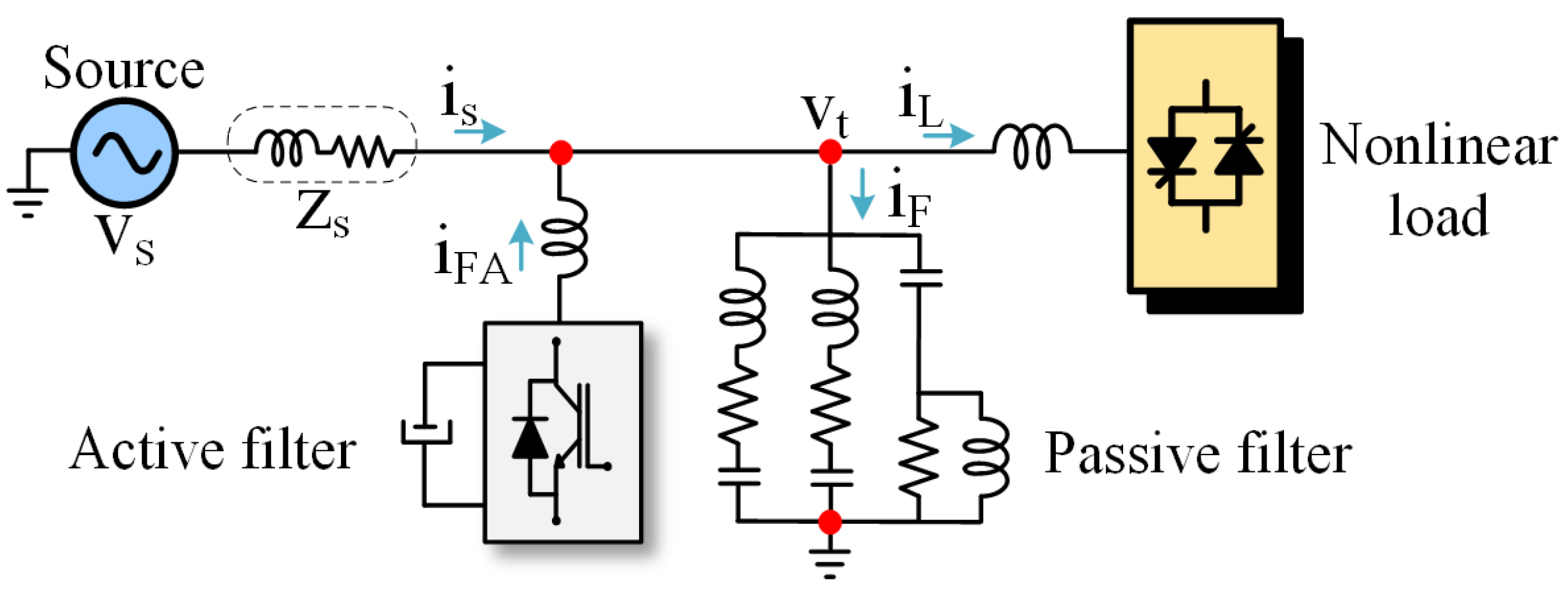
There are two basic structures for a hybrid filter: series and parallel. Figure 1 illustrates the structure of a series hybrid filter, where the active filter is connected in series with the passive filter, and the combination is parallel to the nonlinear load and the electrical grid. In this topology, the active filter improves the harmonic filtering quality of the passive filtering system and is capable of eliminating harmonic resonance. Since most of the voltage is applied to the passive filter, the active filter has low nominal power, making this topology attractive for high-power applications [30,38,39,40].
In a parallel hybrid filter, both the active filter and the passive filter are connected in parallel to the nonlinear load and the electrical grid, as illustrated in Figure 2. In this topology, the passive filter provides a low-impedance path for the harmonic currents of the load, in addition to acting as a reactive power compensator at the fundamental frequency. Meanwhile, the active filter operates by injecting currents that are equal in magnitude but out of phase with the harmonic currents of the nonlinear load, thereby partially or fully canceling out the harmonics. This topology allows the filtering structures to operate independently or in cooperation, allowing for a reduction in the nominal power of the active filter [1,31,41].
A commonly used topology for harmonic compensation is the UPQC, as shown in Figure 3. The UPQC consists of a conditioner made up of two power converters interconnected in series and parallel to the electrical grid. The series-connected converter generates controlled voltages to provide the load with balanced regulated voltages with low harmonic distortion. In turn, the parallel-connected converter produces controlled currents, ensuring that the system currents have low harmonic content, are balanced, and are in phase with the fundamental component [42].

3. Hot Strip Mill Electrical System

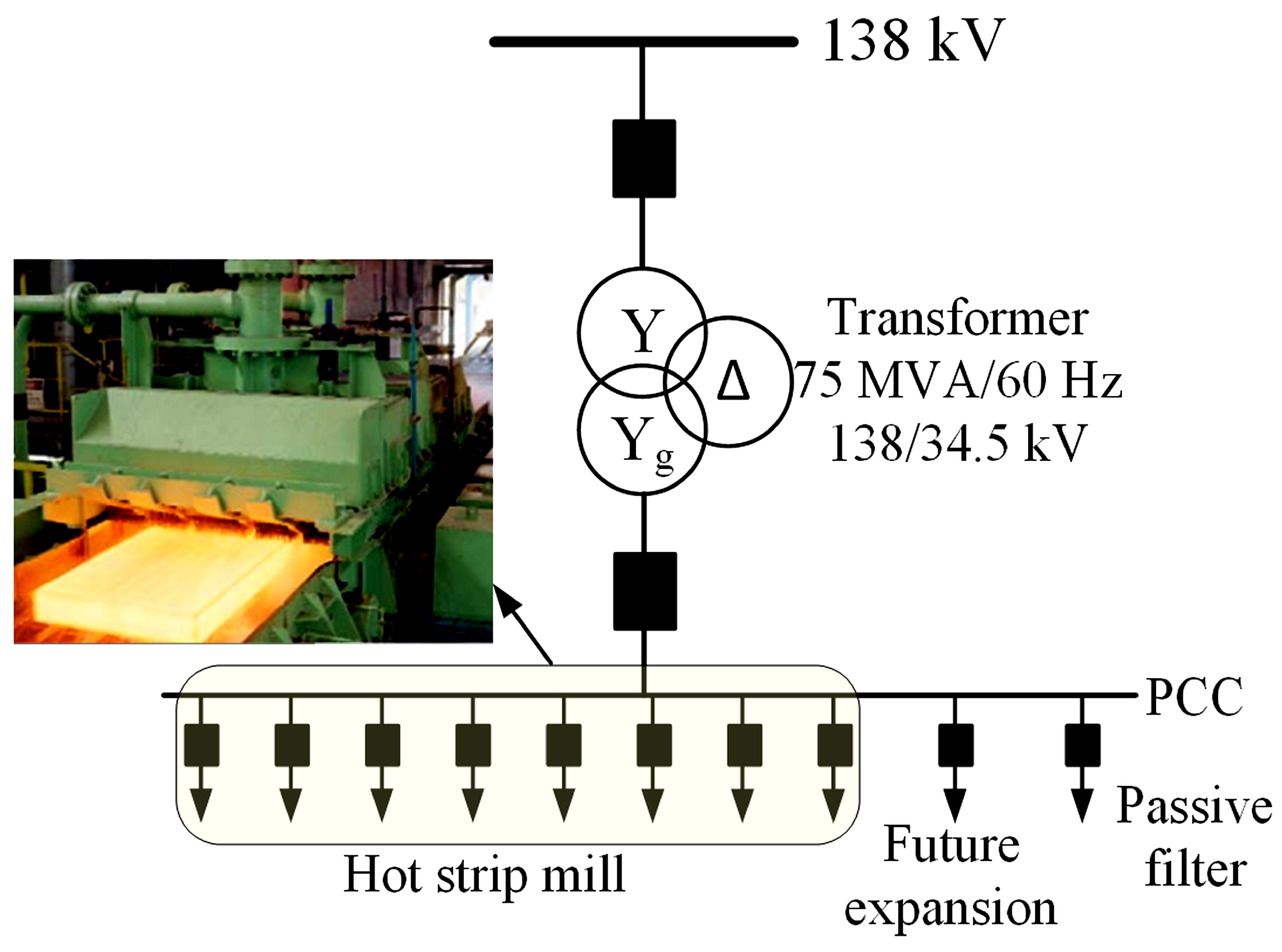
The electrical system of the analyzed steel mill is a three-phase, three-wire system. Its main load is the hot strip mill, powered by synchronous motors and cycloconverters. A bank of passive filters is used for harmonic and reactive power compensation of the load. Figure 4 presents the single-line diagram of the steel mill.
Figure 4 shows that the supply voltage of the system is 138 kV. A step-down transformer supplies the PCC (point of common coupling) at 34.5 kV, where nonlinear loads are connected. The rolling mill includes two synchronous motor units powered by 7.5 MVA cycloconverters in the roughing mill and six 8 MVA units in the finishing mill (rolling stands). The harmonic filtering system is connected to the PCC. Table 2 presents the main nominal power of the hot strip mill’s electrical system [30,31].
For the Matlab/Simulink® model of the electrical system, the transformer is represented from the secondary side as a voltage source that generates only the positive-sequence component. The impedance of the power line and passive filters is determined by technical manuals. The cycloconverter is modeled as a controlled current source, injecting the current measured at the hot strip mill bus into the system. This modeling choice closely approximates the mathematical model to reality, enabling the verification of the system’s behavior in the case of an expansion.
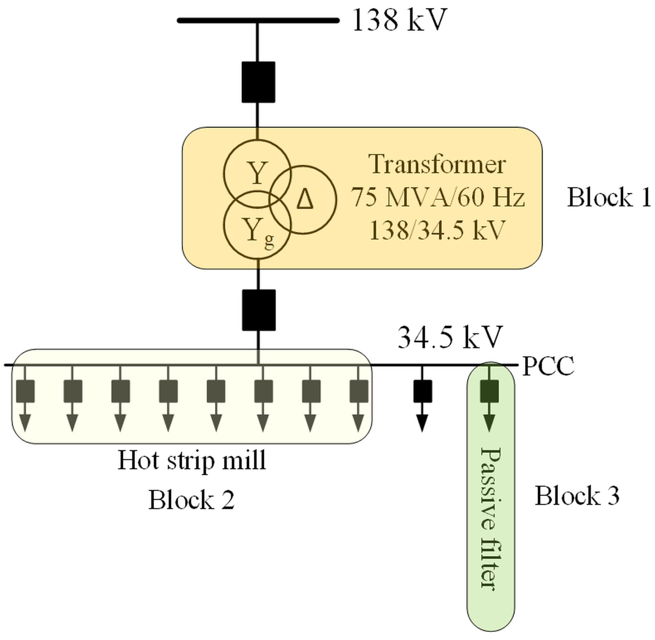
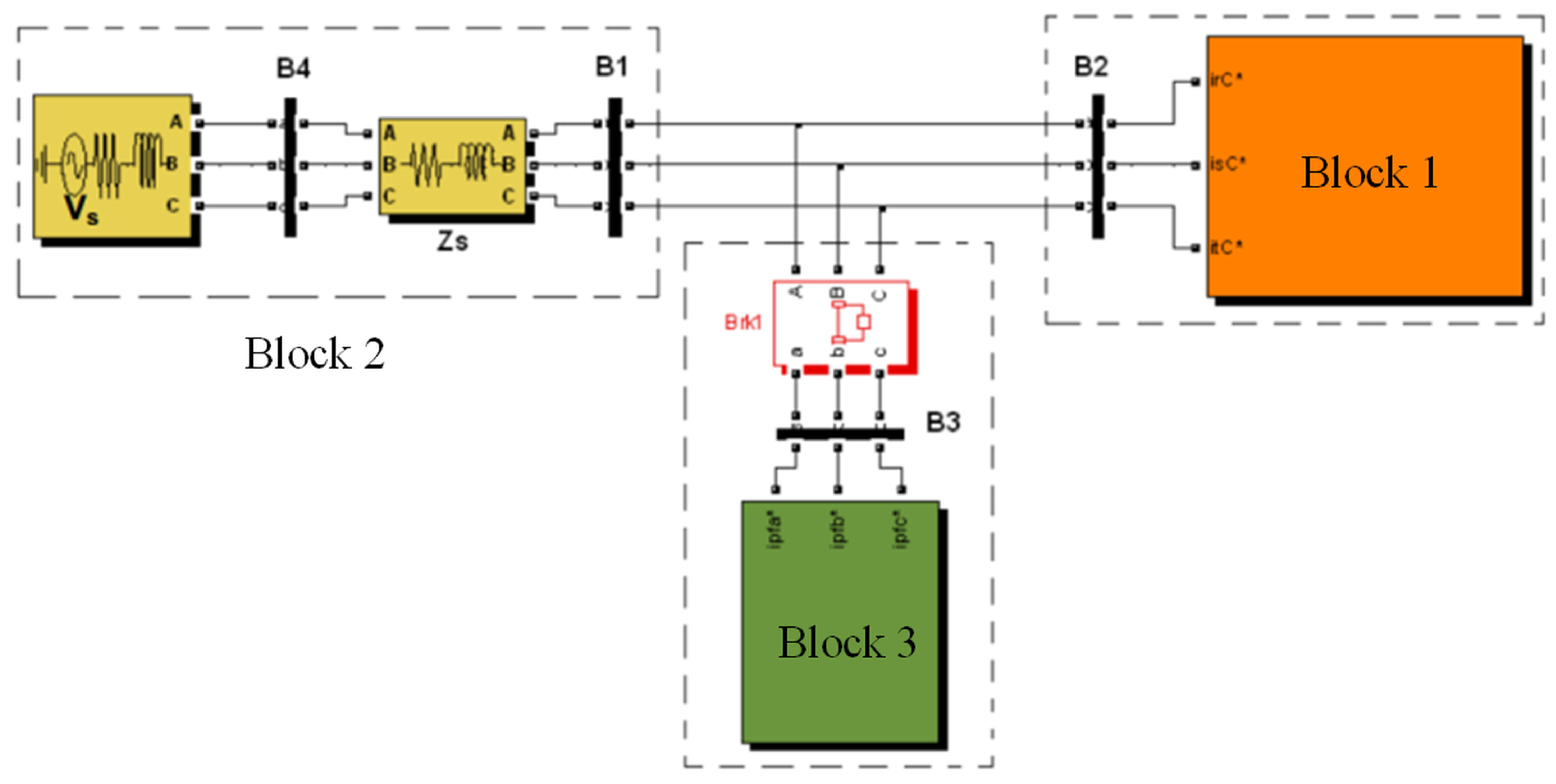
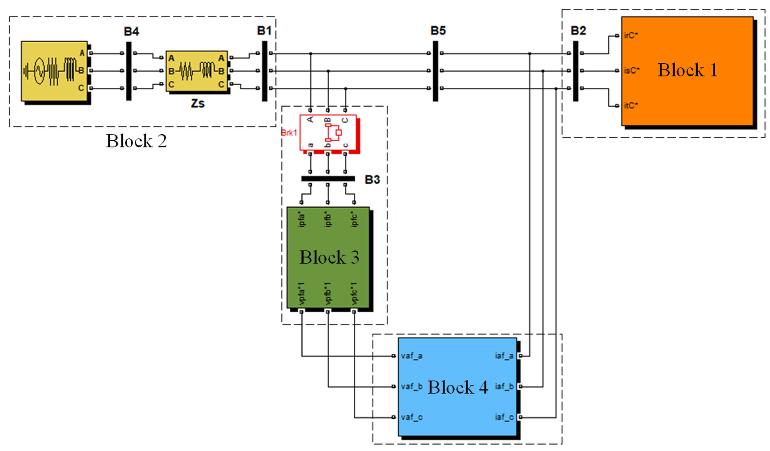
The electrical system model of the hot strip mill, as presented in [30], has a high level of representativeness compared to the real system. In this context, a brief explanation of the development of this model on the Matlab/Simulink® platform is provided to improve the understanding of the results presented. The power system is described using a single-line diagram, as illustrated in Figure 5, and its subdivision into blocks resulted in the system modeled on the Matlab/Simulink® platform, as shown in Figure 6.
The blocks shown in Figure 6 are modeled with the following considerations for representation in Matlab/Simulink®:
  • Block 1 represents a controlled current source representing the set of cycloconverters, injecting the measured currents (50 μs) into the power bus of the electrical system model. This controlled current injection ensures proper system operation.
  • Block 2 represents the system transformer, having a nominal power of 75 MVA and a 138/34.5 kV transformation ratio. This transformer is modeled from the secondary side as a voltage source that generates only the 60 Hz positive-sequence component along with its corresponding impedance. Cables connecting the transformer to the rolling mill substation are also modeled as an impedance. This modeling is appropriate due to the short distance between the transformer and the substation, allowing it to be modeled as a short transmission line.
  • Block 3 represents the passive filtering system, modeled with specific parameters, including resistors, inductors, and capacitors. These parameters were obtained from technical manuals of the hot strip mill, ensuring accurate modeling of the passive filter system.

4. Proposed Back-to-Back Hybrid Filter

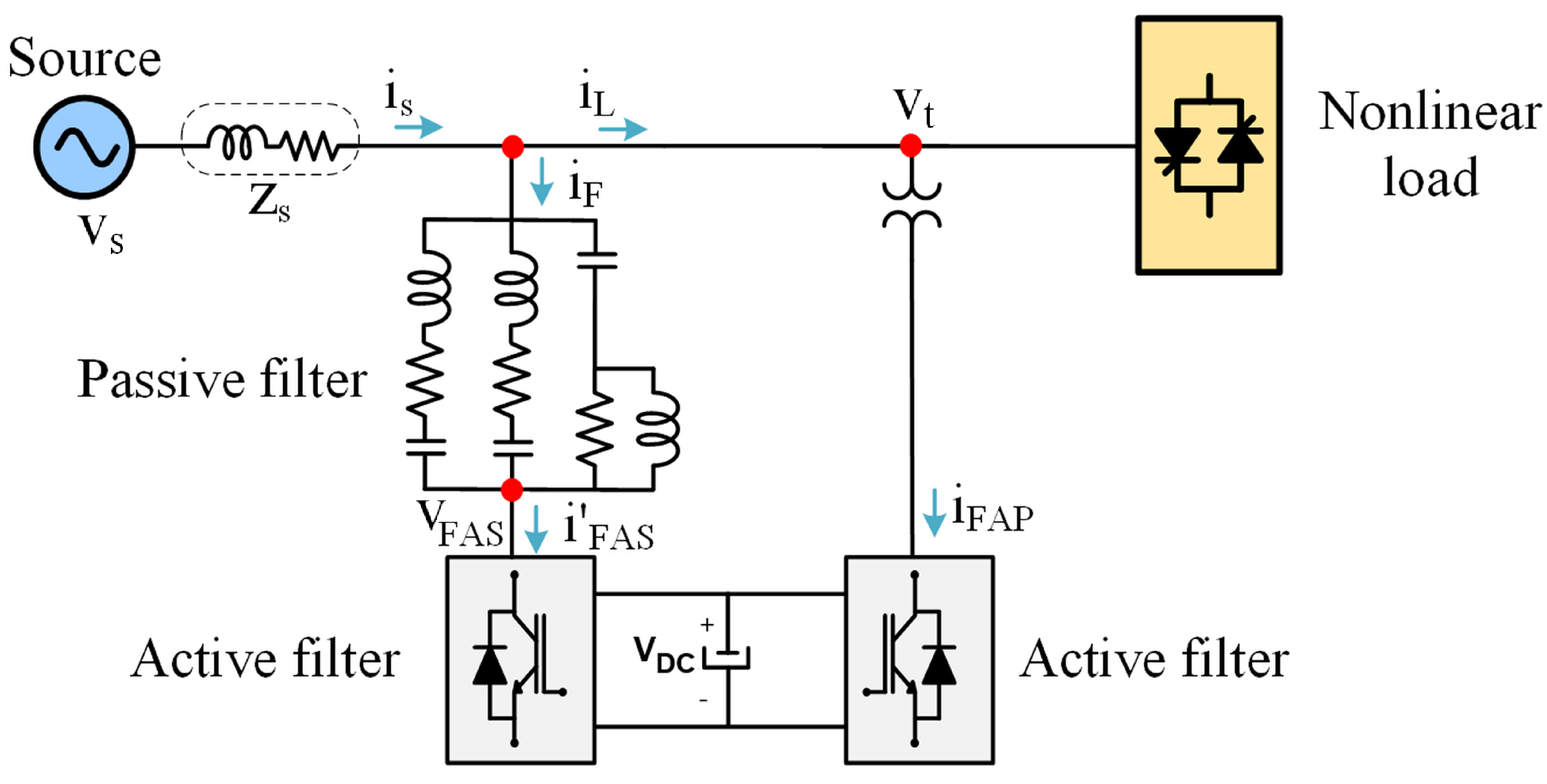
The back-to-back hybrid filter combines the filters mentioned above to enhance their beneficial characteristics and thus optimize the reduction in harmonic components in the electrical network. Figure 7 illustrates the back-to-back hybrid filter analyzed in this project. It is important to note that, unlike the UPQC, the series active filter is directly connected to the passive filter terminals, eliminating the need for a current transformer. The parallel hybrid filter, however, is connected to the grid through a transformer, similar to the UPQC.

4.1. Back-to-Back Hybrid Filter Control

The control algorithms for the back-to-back hybrid filter are based on techniques already implemented in the UPQC, as described in [4]. Furthermore, these algorithms are further refined with additional voltage and current control information described in [43]. Figure 8 illustrates, through a block diagram, the connection between the control modules that make up the series active filter.
Below is a list of the symbols and what they denote:
  • V t —Input voltage vector [ V r e f A V r e f B V r e f C ].
  • i—Input current vector [ i r e f A i r e f B i r e f C ].
  • V h —Voltage vector for harmonic compensation [ V h A V h B V h C ].
  • V P W M —PWM controlled voltage vector [ V P W M A V P W M B V P W M C ].
  • g—Control signals for series hybrid filter.
Figure 9 presents, through a block diagram, the connection between the control modules that make up the parallel active filter.
Below is a list of the symbols and what they denote:
  • V D C —DC link voltage of the inverter;
  • i C C —Current vector for DC bus control [ i C C A i C C B i C C C ];
  • i h —Current vector for harmonic compensation [ i h A i h B i h C ];
  • i r e f —Vector for signal summation ( i C C + i h ).
When analyzing Figure 7 and Figure 8, clear similarities are observed in the control strategies for the series and parallel active filters. However, a fundamental difference lies in the fact that the series active filter operates as a controlled voltage source, while the parallel active filter functions as a controlled current source. The inclusion of a PLL in the control diagrams ensures that the system can synchronize the output frequency of the inverters with the grid frequency. This synchronization is essential to ensure stable operation in compliance with grid standards.
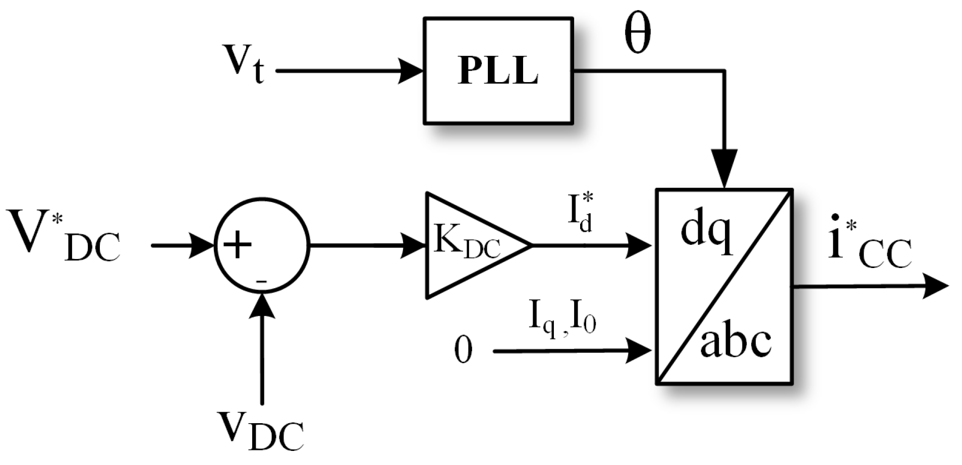
Voltage control in the DC bus is crucial for maintaining appropriate voltage levels, thereby ensuring a stable supply for the inverters. This is especially important in inverter systems, as the quality of the DC bus voltage directly impacts the performance and efficiency of the inverter. One way to draw active power and keep the DC link voltage stable is by injecting a current at the fundamental frequency, in phase with the grid voltage. In this way, active power is absorbed by the inverter, allowing the capacitor voltage to remain constant.
Figure 10 shows a DC bus voltage control scheme for the back-to-back hybrid filter. In the back-to-back configuration, the DC link voltage is regulated using the active filter connected in parallel with the grid. In dq coordinates, an error is generated by comparing the reference voltage with the capacitor voltage, which is subsequently multiplied by a proportional gain, thereby generating a direct-axis current component. Afterward, the inverse synchronous transformation is applied, producing a reference current in the abc coordinates [44].
The voltage and current control loops applied to the series and parallel active filters can be implemented in different reference frames. In [43], an application of repetitive control for the current and voltage loops is presented, achieving harmonic tracking of voltage or current with zero steady-state error and good transient response. Other controllers are presented in [45].

4.2. Harmonic Detection Method

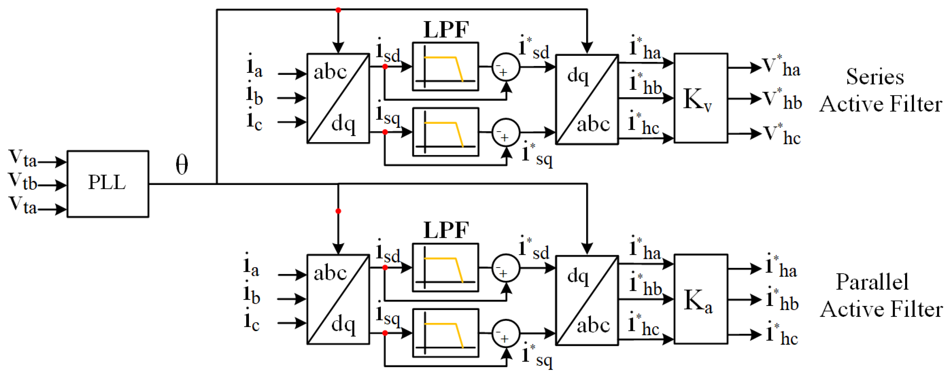
The harmonic detection method is one of the key requirements for efficient harmonic compensation in a hybrid filter. Several algorithms are available to obtain the reference current to be compensated in the nonlinear load. Among these methods, the chosen one was the synchronous reference frame (SRF) method, as shown in Figure 11 [46]. The reference currents for both the series and parallel active filters, in abc coordinates, are sampled by current sensors and transformed into dq coordinates in the synchronous reference frame using the Park transformation. A Phase-Locked Loop (PLL) is used to obtain the grid’s angular frequency and the position of the synchronous axis ( θ ). The dq transformation to the synchronous reference frame is presented in Equation (1). In addition, the low-pass filter (LPF) used is a second-order low-pass filter with a cut-off frequency of 30 Hz, which effectively attenuates higher frequency components.
i d e i q e = 2 3 cos θ 1 cos ( θ 1 2 π 3 ) cos ( θ 1 + 2 π 3 ) sin θ 1 sin ( θ 1 2 π 3 ) sin ( θ 1 + 2 π 3 ) i a i b i c
Below are the symbols and what they represent:
  • i d e and i q e are the direct and quadrature currents in the synchronous reference;
  • i a , i b and i c are the currents of phases a, b, and c in the time domain.

4.3. Harmonic Compensation Principle

In the back-to-back hybrid filter, the control system is divided into two distinct parts that operate concurrently: series and parallel. In the series configuration, the active filter functions as a voltage source controlled by current. On the other hand, in the parallel configuration, the active filter operates as a current source that is also regulated by current.
For the harmonic compensation principle of the back-to-back hybrid filter, two approaches are employed for positioning the active filters. In the first configuration, the series active filter is positioned close to the voltage source, whereas, in the second configuration, the parallel active filter is installed near the grid source, as illustrated in Figure 12.
Below is a list of the symbols above and what they denote:
  • V s —Source voltage;
  • Z s —Source impedance;
  • i s —Source current;
  • Z F P —Impedance of the passive filter;
  • V F A S h —Compensation voltage of the series active filter;
  • i F A S h —Current of the series active filter/passive filter;
  • i F A P h —Compensation current of the parallel active filter;
  • i L —Load current.
Considering that the network voltage is sinusoidal, by applying the Superposition Theorem, it is possible to represent the system as shown in Figure 13, where the load acts as the sole generator of harmonic currents. According to the analysis presented in [31], this approach is used to evaluate the parallel resonance phenomenon within the electrical system.
By analyzing Figure 13 and applying Kirchhoff’s Voltage and Current Laws, Equation (2) is derived, describing both circuits. This shows that there is no difference in the positioning of the active filters within this topology.
i s h . Z s = Z F . i L h Z F . i s h Z F . i F A P h V F A S h
The harmonic compensation principle for the back-to-back hybrid filter relies on Equation (2). These techniques involve the possibility of evaluating four currents in the circuit, as illustrated in Figure 13:
  • i s h —Source current;
  • i L h —Intermediate load current;
  • i L h —Load current;
  • i F h —Passive filter current.
Using this approach, sixteen (16) distinct compensation techniques are identified, derived from a combinatorial analysis of all potential combinations of two of these currents. This article focuses specifically on identifying and highlighting the most effective compensation technique for the back-to-back hybrid filter.

5. Comparison of Harmonic Compensation Techniques

The 16 compensation techniques are sequentially organized from 1 to 16. After a thorough evaluation, it was determined that the fourth technique on the list is the most effective for the back-to-back hybrid filter.

5.1. Technique 4

In this technique, the series active filter produces a voltage at the common termination of the passive filter, controlled by the harmonic components of the source current according to the following relationship:
V F A S h = K v . i s h ( t )
The constant K v in Equation (3) represents the gain of the series active filter and is expressed in units of Ohms ( Ω ). The parallel active filter generates a current, controlled by the harmonic components of the load current, as described by the relationship
i F A P h = K a . i L h ( t )
The constant K a in Equation (4) represents the gain of the parallel active filter and is dimensionless. Substituting Equations (3) and (4) into Equation (2), yields the following relationships:
i s h i L h = Z F ( 1 K a ) Z S + Z F + K v
i F h i L h = Z s ( K a 1 ) + K v ( K a 1 ) Z S + Z F + K v
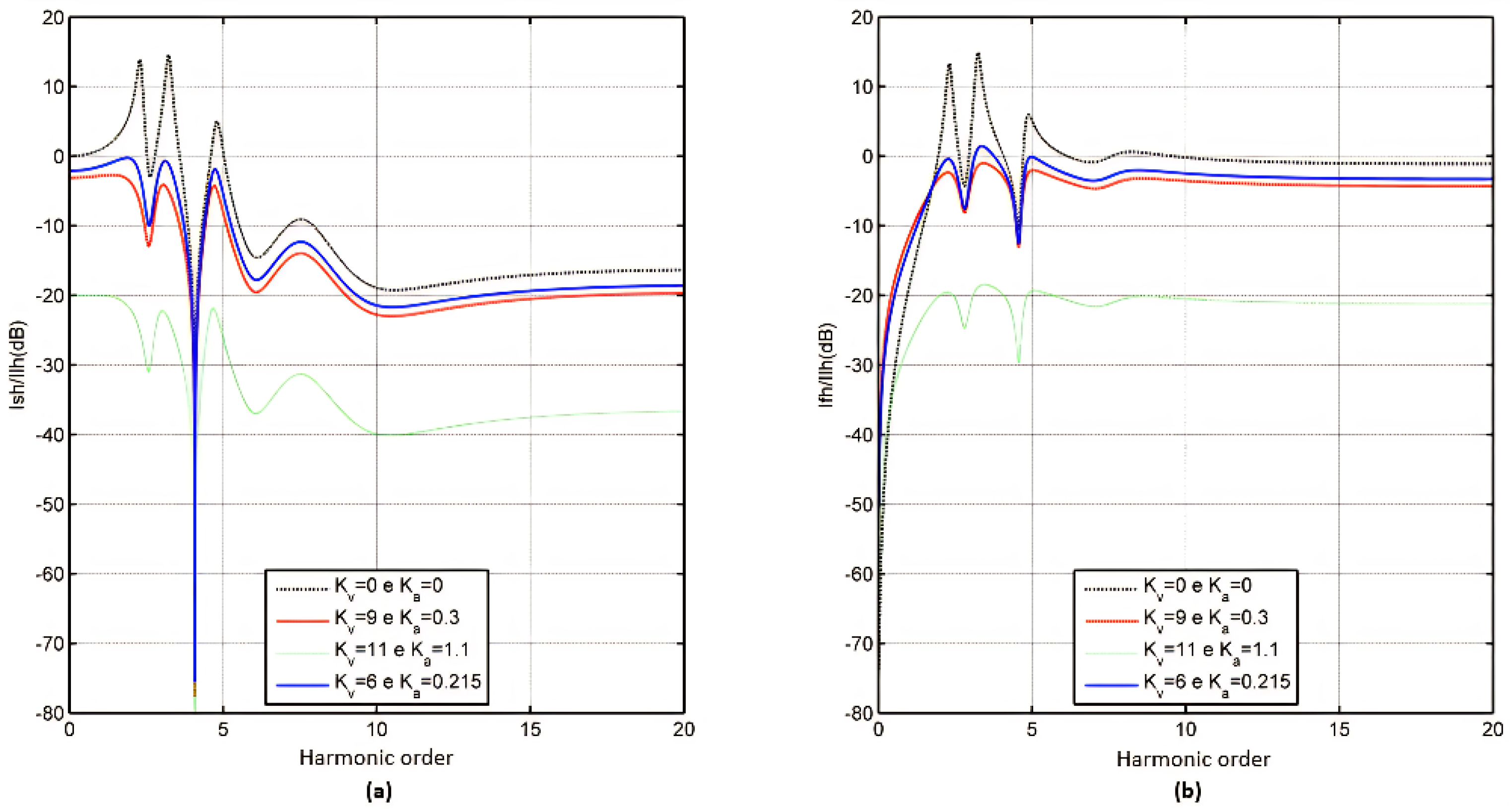
Figure 14 illustrates the transfer function corresponding to technique 4, with values of K v and K a .
Based on the analysis in Figure 14, it is possible to significantly reduce the parallel harmonic amplification of the system using values of K v = 6 and K a = 0.215 . In this configuration, the parallel active filter injects currents in opposition to the harmonic currents, sufficient for the passive filter to absorb the remaining harmonic components generated by the load, resulting in a source current with minimal harmonics or no harmonics. Consequently, technique 4 is demonstrated to be an effective method for the back-to-back hybrid filter topology.

5.2. Overview of the Techniques Applied to the Back-to-Back Hybrid Filter

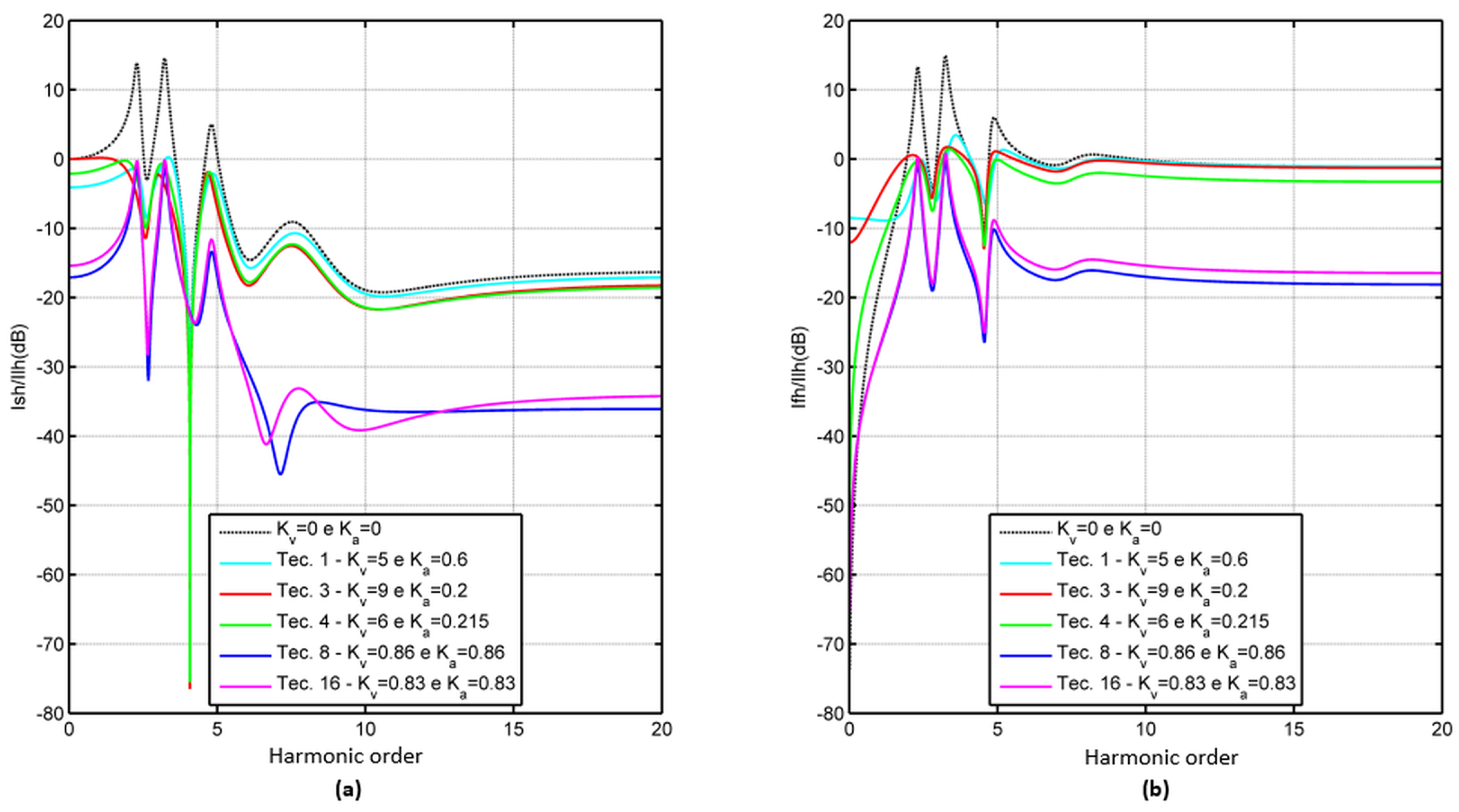
When evaluating and inferring all the techniques applicable to the back-to-back hybrid filter, it is important to note that not all of them are suitable for this topology. However, a few techniques were identified as capable of reducing harmonic amplification in the power grid, thus meeting the condition of maintaining the amplification spectrum of the i s h / i l h transfer function below 0 dB. These techniques prove to be effective only when the appropriate values of K v and K a are used. Table 3 summarizes the techniques that were successfully applied to the back-to-back hybrid filter.
Figure 15 shows, in a single graph, the transfer functions of the techniques that were considered suitable for the back-to-back hybrid filter. Each of these techniques exhibits distinct characteristics. In particular, techniques 3 and 4 share similar characteristics in their response, while techniques 8 and 16 stand out by achieving a more significant reduction in harmonics at high frequencies.

6. Simulation Model of the Back-to-Back Hybrid Filter

One way to evaluate the performance of the back-to-back hybrid filter to damp parallel resonance and compensate for harmonics in the electrical system of the hot strip mill is to use a specific model for simulation. In this context, it is possible to adopt the model proposed in [30], which was implemented using the Matlab/Simulink® platform. It is important to note that the developed model uses the parallel active filter as a controlled current source and the series active filter as a controlled voltage source, both operating based on a reference current, without any losses.
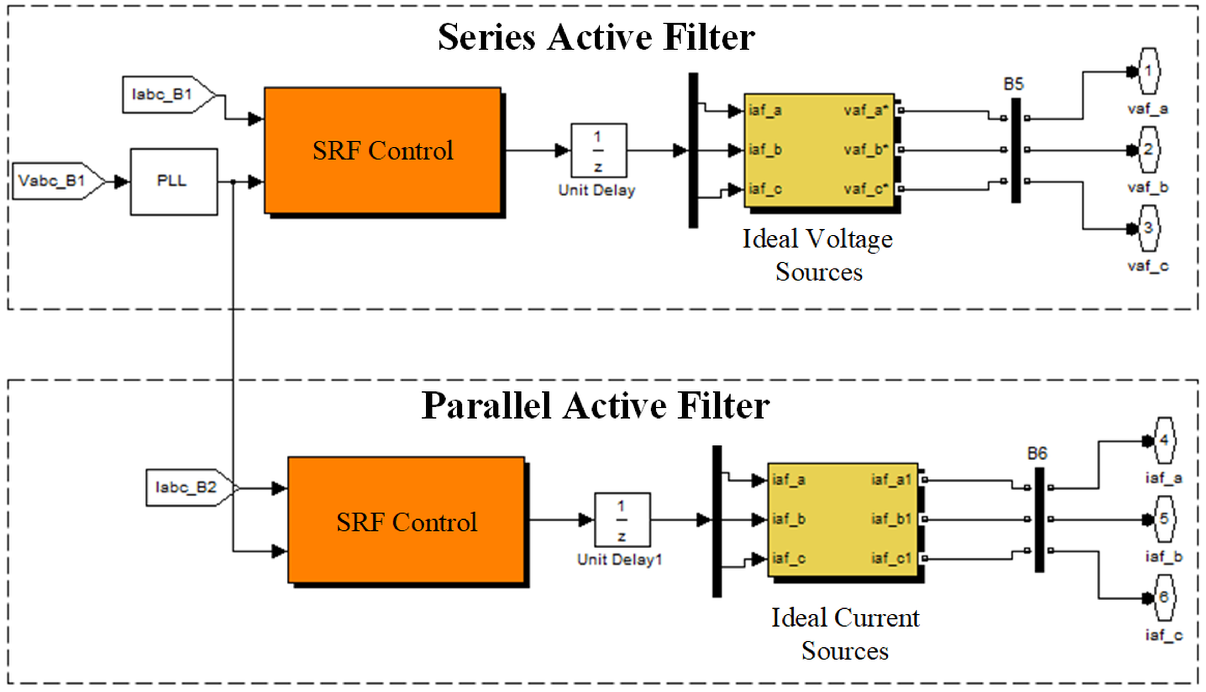
The entire electrical system model of the hot strip mill is fully developed in Matlab/Simulink® software (version 2007b), utilizing the Simscape library with an integration step of 50 µs. Figure 16 illustrates the back-to-back hybrid filter implementation within the Matlab/Simulink® environment. It is also important to note that Blocks 1, 2, and 3 have already been described earlier in this paper. Figure 17 shows the composition of the back-to-back hybrid filter, highlighting the following elements:
  • PLL;
  • Harmonic detection method using an SRF-type control algorithm;
  • Ideal controlled current and voltage sources.
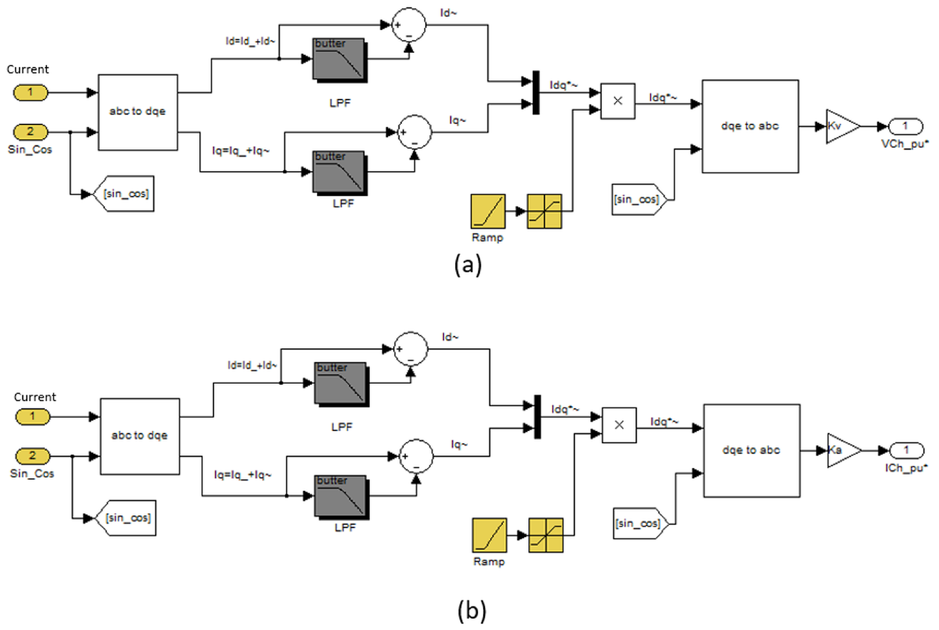
Figure 18 illustrates the SRF control details, which are utilized in both the series active filter and the parallel active filter. The information shown in Figure 18a corresponds to the series active filter, while the information in Figure 18b pertains to the parallel active filter. The only difference between the controls is that the currents generated by the harmonic detection method for the series active filter are multiplied by a gain K v . However, those for the parallel active filter are multiplied by a gain K a .

7. Simulation Results of the Back-to-Back Hybrid Filter

In this section, the most relevant waveforms for the back-to-back hybrid filter applied to the hot strip mill’s electrical system are evaluated. This analysis includes an examination of the waveforms before and after the activation of the active filter at 0.3 s. Furthermore, we analyzed the frequency spectrum associated with each relevant electrical quantity. A 30% load expansion for the cycloconverters was considered, and the results are presented below.

7.1. Simulation Results—Technique 4

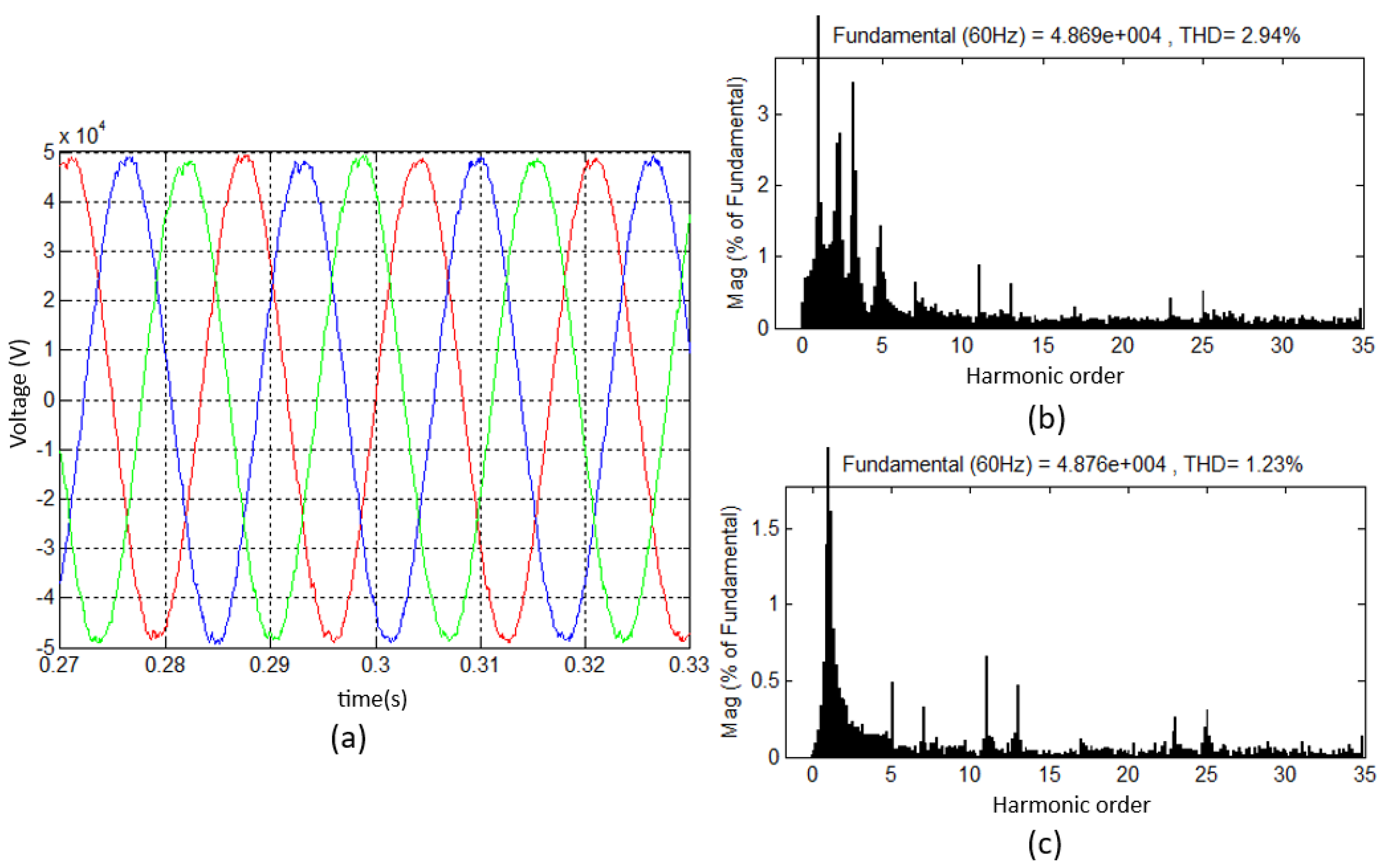
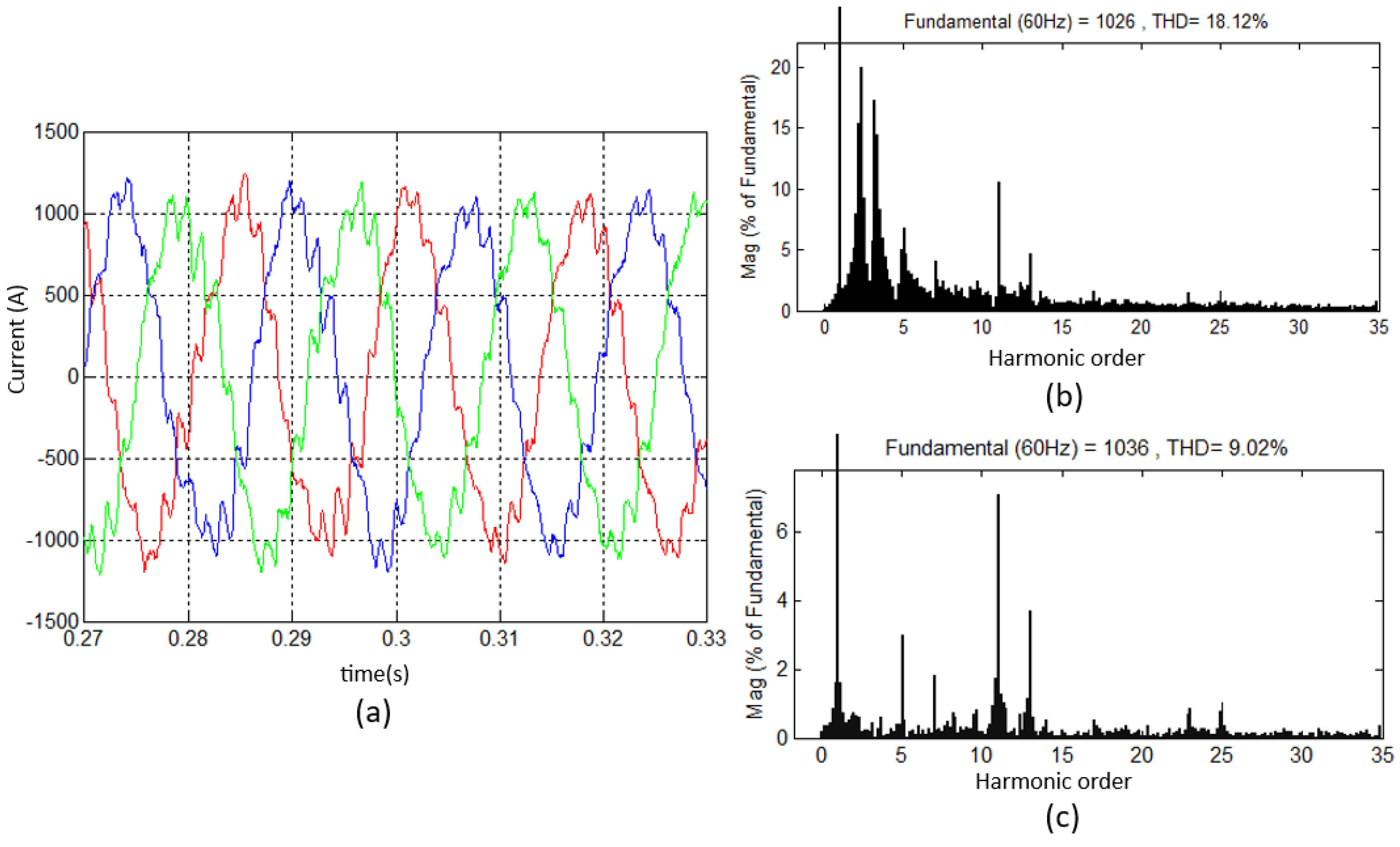
By controlling the output voltage of the series active filter based on the harmonic portions of the source current and the output current of the parallel active filter, which is controlled by the load current, the values obtained are K v = 6 and K a = 0.215 , as derived from Equations (5) and (6). Figure 19, Figure 20 and Figure 21 illustrate the current and voltage waveforms at the PCC and the current in the hot strip mill’s passive filter bank for technique 4.
By analyzing the harmonic spectrum of the current and voltage at the PCC before and after connecting the back-to-back hybrid filter, it is evident that harmonic amplification between the fundamental frequency and the harmonics up to the fifth order is significantly reduced. Higher-order harmonic components also exhibit a reduction in amplitude, though to a lesser extent. This underscores the effective performance of the back-to-back hybrid filter in mitigating harmonic distortion at higher frequencies.
After applying technique 4 to connect the back-to-back hybrid filter, a significant reduction in voltage harmonic distortion of 58.16% and current harmonic distortion of 40.86% at the point of common coupling was observed. In addition, the harmonic distortion of the current in the passive filter was reduced by 50.22%. These results demonstrate the effectiveness of technique 4 in mitigating harmonic distortion in the electrical system.
To determine the rating of a series and parallel active filter, it is necessary to use Equation (7), which was developed in [35]:
| S F A | = 3 × V C C 2 × I F A 2
Below is a list of the symbols above and what they denote:
  • P F A : Nominal active power;
  • V C C : Voltage on the DC link;
  • I F A : Current in the active filter.
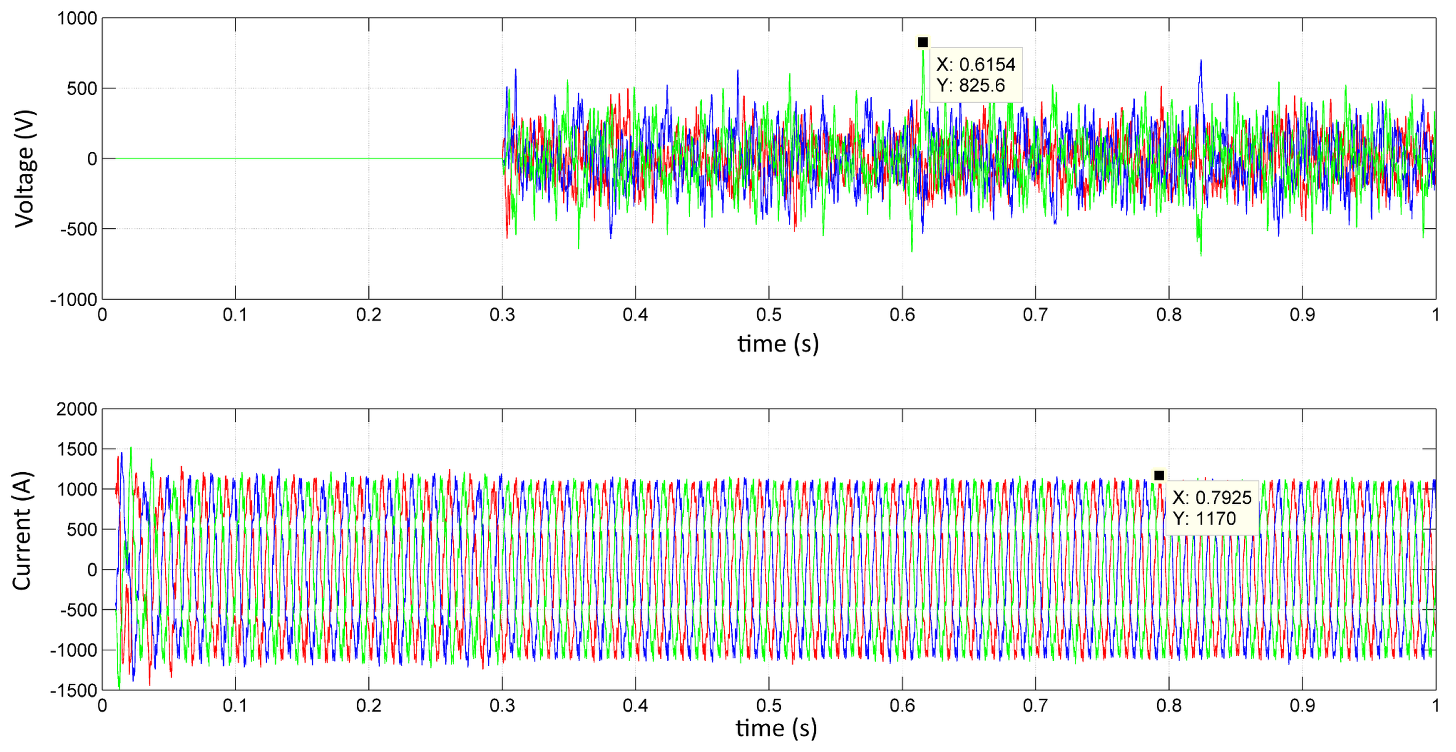
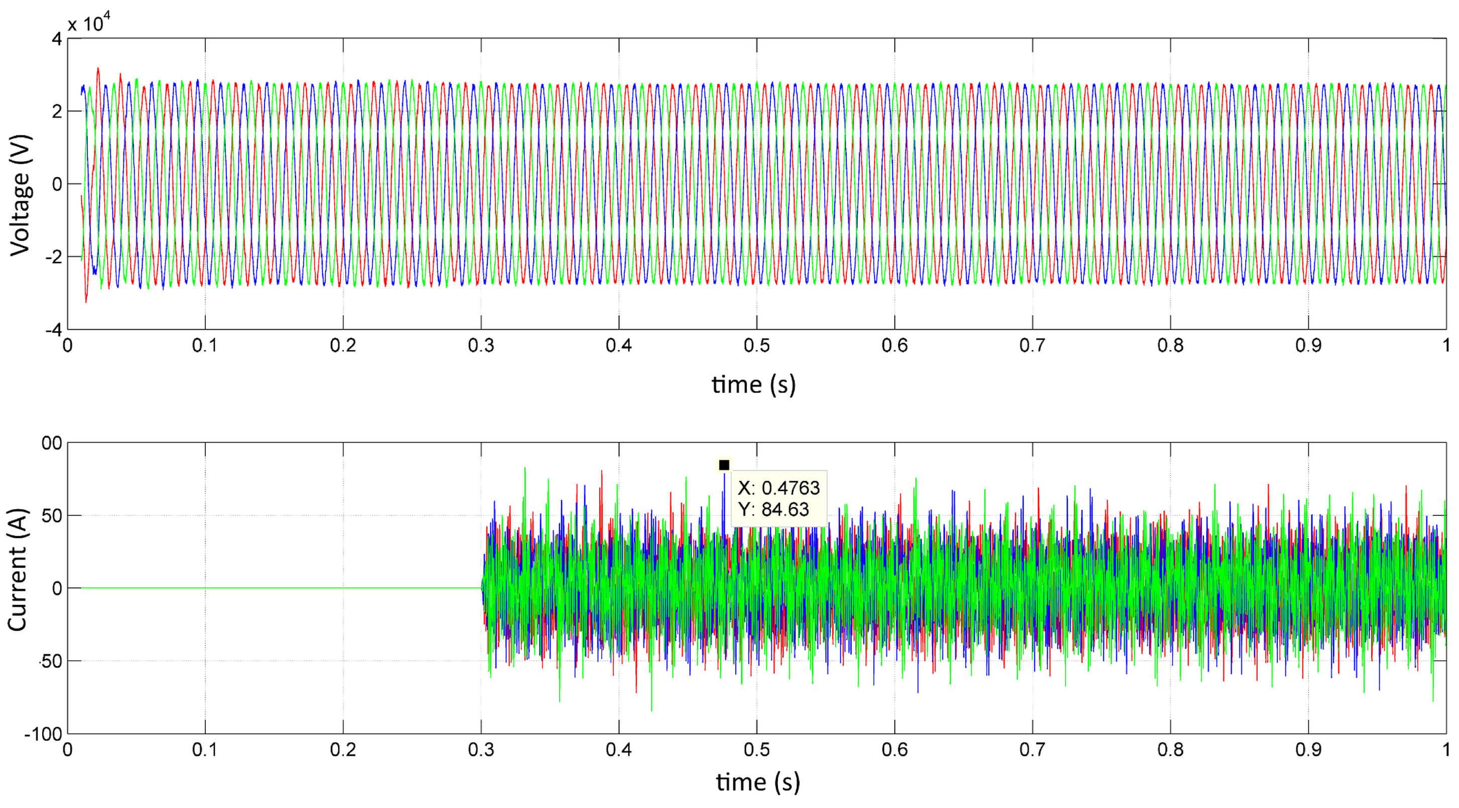
Using a three-phase inverter with two-level PWM modulation and a hysteresis-based current regulator, the voltage on the capacitor must be greater than the maximum peak voltage across the phases at the inverter terminals. Figure 22 and Figure 23 show the voltages and currents synthesized by the series and parallel active filters, respectively.
In this case, for the series active filter, we have the following expression:
| S S A F | = 3 × ( 2 × 825.6 ) 2 × 1170 2 = 1.67 M V A
The expression for the parallel active filter is as follows:
| S P A F | = 3 × 34.5 k V × 84.63 2 = 3.57 M V A
To demonstrate the effectiveness of the back-to-back hybrid filter with technique 4, Table 4 presents the effective current values in the branches of the passive filtering system currently deployed in the hot strip mill.
An examination of Table 4 reveals that applying technique 4 effectively eliminates all overloads in the passive filter branches. Therefore, technique 4 demonstrates its efficiency in reducing voltage and current harmonics at the PCC, while successfully resolving the overload issue in all passive filter branches.

7.2. Overview of Back-to-Back Hybrid Filter Simulation Results

Table 5 compares the current values in the passive filter branches in relation to the techniques applied to the back-to-back hybrid filter. From Table 5, blue color indicates current values below the nominal value, representing satisfactory operation without overload. In contrast, red color indicates current overload, highlighting values exceeding nominal capacity, which suggests potential issues in the passive filter branches.
The analysis of Table 5 reveals that technique 1 failed to eliminate the overload in the passive filter branches, despite achieving positive results in reducing the harmonic components of voltage and current at the PCC. On the other hand, techniques 8 and 16 succeeded in reducing the voltage and current harmonic components at the PCC and eliminating the overload in the passive filter branches. However, this was achieved at a very high cost due to the high power rating required for the parallel hybrid filter, making their use impractical compared to the two most effective techniques, i.e., techniques 3 and 4. Table 6 presents a comparison of the voltage and current THD values for the techniques applied to the back-to-back hybrid filter.
When analyzing Table 6, it can be seen that techniques 3 and 4 showed similar results in reducing the harmonic components of voltage and current at the PCC and in the branch currents of the passive filter, effectively eliminating all existing overloads with the expansion in 30% of the hot strip mill. However, technique 4 demonstrated superior performance due to the lower added power of the active filters. Therefore, it can be concluded that technique 4 is the best option for the back-to-back hybrid filter topology.
Table 7 presents the comparison of THD reduction for voltage and current at the PCC, as well as passive filter current, relative to the passive filter solution. Although technique 16 achieved the best results for THD reduction, it required an active filter with a higher nominal rating compared to technique 4. Based on this criterion, technique 4 was selected as the optimal approach.

7.3. Performance Analysis of the Back-to-Back Hybrid Filter Against Other Solutions

The authors of [31] conducted a detailed study of the same hot strip mill analyzed in this paper, providing additional information about the implementation of a series hybrid filter and a parallel hybrid filter, as well as using the existing installations. This study contributed relevant information to the topic explored, expanding the possibilities of solutions to harmonics problems in the electrical system. Therefore, comparing the topologies studied in [39] with the topology presented in this paper is possible.
Table 8 compares the current values in the branches of the passive filters using the back-to-back hybrid filter with technique 4, alongside the series and parallel hybrid filters analyzed in [39].
By analyzing Table 8, it is clear that using the series hybrid filter alone is not enough to eliminate the overload in the passive filter branches with the expansion in 30%. However, with the parallel hybrid filter, it is possible to eliminate all the overload but with a very high power requirement for the active filter, making its use economically unfeasible. Table 9 compares the voltage and current THD values at the PCC and current in the passive filter.
Table 9 shows that the back-to-back hybrid filter, as well as the hybrid filters studied in [39], significantly reduce the harmonic distortions of both voltage and current at the PCC, as well as in the current of the passive filter. Upon analyzing the results of the parallel hybrid filter, it can be observed that the THDs are low; however, this reduction is achieved through the use of an active filter with a high nominal capacity, as indicated in Table 8. Compared to the parallel hybrid filter, where the overload on the passive filter branches has been eliminated, the back-to-back filter represents a more practical and cost-effective option.
However, as presented above, the back-to-back hybrid filter proves to be a viable option, as it effectively eliminates overload in passive filtering branches requiring less power from active filters compared to the other topologies analyzed. Therefore, it is crucial to emphasize the superior effectiveness of the back-to-back hybrid filter over the other topologies, making it a promising solution to mitigate overload in the passive filter branches, even with a load expansion of 30% in the hot strip mill.

8. Conclusions

This paper presents a case study conducted in a steel mill located in the Grande Vitória region that employs the hot strip rolling process. The study included an analysis of the harmonic components in the low-speed drives of the synchronous motors in the rolling mills, which are controlled by high-power cycloconverters.
The results indicate that cycloconverters represent an electrical load with a low power factor and significantly distorted current, exhibiting a wide harmonic spectrum. Given these characteristics, the implementation of passive filters with multiple filtering stages is essential to improve PQ in the rolling mill electrical system. These filters effectively reduce unwanted harmonics and contribute to improving the overall efficiency of the electrical system during the hot strip rolling process.
After analyzing the measurements taken at the rolling mill substation, it was found that voltage and current distortions at the PCC were found to comply with the standards established by IEEE 519 and PRODIST Module 8. However, it was observed that the electrical system is susceptible to harmonic resonance, resulting from the interaction between the impedance of the power grid and the passive filtering system. This phenomenon leads to harmonic amplification in the mains current and the passive filtering system over a wide frequency range. Consequently, the voltage and current harmonic distortion levels at the PCC are high, which results in an overload of the passive filtering system.
To carry out a more in-depth study of the hot strip mill’s electrical system to identify suitable solutions for resonance damping and harmonic compensation, a model was developed in the Matlab/Simulink® environment. This model accurately represents the real electrical system of the mill, providing a high level of fidelity. By using the parameters of the electrical system, it was possible to see significant amplification in the main current and in the passive filtering system, which was primarily due to parallel resonance. Therefore, by modeling the transformer secondary as a voltage source with positive sequence, a realistic analysis of harmonic amplification could be obtained.
After conducting an extensive literature search on filters to minimize the effects of harmonic amplification in the typical electrical system of the hot strip mill under study, hybrid filters were identified as a promising option. Previous studies have shown that these filters perform better in high-power applications. Moreover, there are well-established studies that highlight the effectiveness of series and parallel hybrid filters in industries utilizing hot strip mills. However, it is important to note that the specific topology of the back-to-back hybrid filter proposed in this paper is novel and had not been reported in the literature at the time of writing.
The adoption of a back-to-back hybrid filter in the passive filtering system led to significant improvements in the PQ of the hot strip mill’s electrical system. By eliminating harmonic resonance, the filter reduces voltage and current harmonic distortion levels in the electrical system. Moreover, the overloading of the passive filter system was also eliminated. It is important to note that the back-to-back hybrid filter achieved all these PQ improvements while using only two active filters of relatively low nominal capacity, compared to the requirements of the parallel hybrid filter.
This study has demonstrated that a hybrid filter configuration, comprising an active filter in series and an active filter in parallel, in conjunction with an existing passive filter, is suitable for implementation in a steel mill that utilizes a hot strip mill in its system.
For future research on this topic, it is recommended to explore variations in hot strip mill load or to integrate alternative hybrid filter topologies to further improve PQ.

Author Contributions

Conceptualization, R.C.K.K. and H.M.A.A.; methodology, R.C.K.K. and H.M.A.A.; software, R.C.K.K.; validation, R.C.K.K.; formal analysis, R.C.K.K.; investigation, R.C.K.K.; resources, R.C.K.K. and H.M.A.A.; data curation, R.C.K.K.; writing—original draft preparation, R.C.K.K. and H.M.A.A.; writing—review and editing, R.C.K.K. and H.M.A.A.; visualization, R.C.K.K. and H.M.A.A.; supervision, R.C.K.K. and H.M.A.A.; project administration, R.C.K.K. and H.M.A.A.; funding acquisition, R.C.K.K. and H.M.A.A. All authors have read and agreed to the published version of the manuscript.

Funding

This study was financed in part by the Coordenação de Aperfeiçoamento de Pessoal de Nível Superior—Brasil (CAPES)—Finance Code 001.

Data Availability Statement

Data are contained within the article.

Acknowledgments

The authors thank the Graduate Program in Electrical Engineering of the Federal University of Espirito Santo for supporting this research, and the government agencies CAPES and CNPQ for their financial support.

Conflicts of Interest

The authors declare no conflicts of interest.

References

  1. Chen, C.; Lee, Y.; Hsu, C.; Ting, D.; Shen, C. Power quality assessment of a hot strip mill with cycloconverter drive systems. In Proceedings of the 2007 IEEE Industry Applications Annual Meeting, New Orleans, LA, USA, 23–27 September 2007; pp. 9–16. [Google Scholar]
  2. Pittner, J.; Simaan, M.A. Main Drives and Motors. In Tandem Hot Metal Rolling Mill Control: Using Practical Advanced Methods; Springer International Publishing: Cham, Switzerland, 2024; pp. 169–188. [Google Scholar] [CrossRef]
  3. Orcajo, G.A.; Rodríguez, D.J.; Cano, J.M.; Norniella, J.G.; Ardura, G.P.; Llera, T.R.; Diego Cifrián, R. Dynamic estimation of electrical demand in hot rolling mills. In Proceedings of the 2015 IEEE Industry Applications Society Annual Meeting, Addison, TX, USA, 18–22 October 2015; pp. 1–9. [Google Scholar] [CrossRef]
  4. Khadkikar, V. Enhancing electric power quality using UPQC: A comprehensive overview. IEEE Trans. Power Electron. 2011, 27, 2284–2297. [Google Scholar] [CrossRef]
  5. Park, B.; Lee, J.; Yoo, H.; Jang, G. Harmonic mitigation using passive harmonic filters: Case study in a steel mill power system. Energies 2021, 14, 2278. [Google Scholar] [CrossRef]
  6. Orcajo, G.A.; Rodríguez, J.; Cano, J.M.; Norniella, J.G.; Ardura, P.; Llera, R.; Cifrián, D. Retrofit of a hot rolling mill plant with three-level active front end drives. IEEE Trans. Ind. Appl. 2018, 54, 2964–2974. [Google Scholar] [CrossRef]
  7. Hulshorst, W.T.; Keet, A.L.; Enslin, J.H. Harmonic Analyses and Mitigation in Large Industrial Steel Plants A Case Study. Electr. Power Qual. Util. Mag. 2006, 2, 1–7. [Google Scholar]
  8. Orcajo, G.A.A.; Diez, J.R.; Cano, J.M.; Norniella, J.G.; González, J.F.P.; Rojas, C.H.; Ardura, P.; Cifrián, D. Enhancement of power quality in an actual hot rolling mill plant through a STATCOM. IEEE Trans. Ind. Appl. 2020, 56, 3238–3249. [Google Scholar] [CrossRef]
  9. Karandaev, A.; Kornilov, G.; Khramshin, V.; Khramshin, T. Improving electric power quality within the power supply system of wide-strip hot-rolling mill stand. Procedia Eng. 2015, 129, 2–8. [Google Scholar] [CrossRef]
  10. Liu, Y.; Heydt, G.T.; Chu, R.F. The power quality impact of cycloconverter control strategies. IEEE Trans. Power Deliv. 2005, 20, 1711–1718. [Google Scholar] [CrossRef]
  11. Aravena, P.; Morán, L.; Dixon, J.; Espinoza, J.; Godoy, O. A new hybrid filter topology for sub and inter-harmonic attenuation in cycloconverter-fed drives applications. In Proceedings of the 2009 IEEE Industry Applications Society Annual Meeting, Houston, TX, USA, 4–8 October 2009; pp. 1–7. [Google Scholar]
  12. Antunes, H.M.; Pires, I.A.; Silva, S.M. Evaluation of series and parallel hybrid filters applied to hot strip mills with cycloconverters. IEEE Trans. Ind. Appl. 2019, 55, 6643–6651. [Google Scholar] [CrossRef]
  13. Ardura, P.; Alonso, G.; Cano, J.M.; Norniella, J.G.; Pedrayes, F.; Briz, F.; Cabanas, M.F.; Melero, M.G.; Rojas, C.; Suárez, J.R.G.; et al. Power quality analysis and improvements in a hot rolling mill using a STATCOM. Renew. Energy Power Qual. J. 2014, 1, 582–587. [Google Scholar]
  14. Hörger, I. Aspects for filter design in case of cycloconverter load. Power Qual. 1997, 97, 10–12. [Google Scholar]
  15. Basic, D.; Ramsden, V.; Muttik, P. Harmonic and reactive power compensation of high power cycloconverter induction motor drives by using decoupled inverters. In Proceedings of the 1998 International Conference on Power Electronic Drives and Energy Systems for Industrial Growth, Perth, WA, Australia, 1–3 December 1998; Volume 1, pp. 44–49. [Google Scholar]
  16. Yousif, S.; Wanik, M.; Mohamed, A. Implementation of different passive filter designs for harmonic mitigation. In Proceedings of the PECon 2004. Proceedings. National Power and Energy Conference, Kuala Lumpur, Malaysia, 29–30 November 2004; pp. 229–234. [Google Scholar]
  17. Zhai, X.; Zhuo, F.; Duan, R.; Lei, W.; Zhang, P.; Wang, Z. Development of a parallel hybrid power filter with respective harmonic compensation method. In Proceedings of the Twenty-First Annual IEEE Applied Power Electronics Conference and Exposition, Dallas, TX, USA, 19–23 March 2006; p. 5. [Google Scholar]
  18. Singh, B.; Verma, V.; Chandra, A.; Al-Haddad, K. Hybrid filters for power quality improvement. IEE Proc.-Gener. Transm. Distrib. 2005, 152, 365–378. [Google Scholar] [CrossRef]
  19. Na, H.; Jian, W.; Dianguo, X. A novel shunt hybrid power filter for suppressing harmonics. In Proceedings of the 2006 IEEE International Symposium on Industrial Electronics, Montreal, QC, Canada, 9–13 July 2006; Volume 2, pp. 1155–1160. [Google Scholar]
  20. Seifossadat, S.G.; Kianinezhad, R.; Ghasemi, A.; Monadi, M. Quality improvement of shunt active power filter, using optimized tuned harmonic passive filters. In Proceedings of the 2008 International Symposium on Power Electronics, Electrical Drives, Automation and Motion, Ischia, Italy, 11–13 June 2008; pp. 1388–1393. [Google Scholar]
  21. Shimamura, T.; Kurosawa, R.; Hirano, M.; Uchino, H. Parallel operation of active and passive filters for variable speed cycloconverter drive systems. In Proceedings of the 15th Annual Conference of IEEE Industrial Electronics Society, Philadelphia, PA, USA, 6–10 November 1989; pp. 186–191. [Google Scholar]
  22. Ferreira, C.; Simonetti, D.; Sousa, G. Analysis of an Active Filter in Parallel with Cycloconverters and Passive Filters in a System of Metallurgical Lamination. In Proceedings of the Annals of the XVII Brazilian Congress of Automatic, Santos, Brazil, 2007. [Google Scholar]
  23. Bessadet, I.; Tedjini, H. The performances of hybrid filter in elimination of AC-AC converters harmonics pollution. In Proceedings of the 2018 6th International Renewable and Sustainable Energy Conference (IRSEC), Rabat, Morocco, 5–8 December 2018; pp. 1–6. [Google Scholar]
  24. Obando, J.A.; Serrano, V. Implementation of a Hybrid ANN-Based Filter for the Reduction of Harmonic Currents. Eur. J. Electr. Eng. Int. De Génie Electr. 2021, 23. [Google Scholar] [CrossRef]
  25. Basic, D.; Ramsden, V.; Muttik, P. Selective compensation of cycloconverter harmonics and interharmonics by using a hybrid power filter system. In Proceedings of the 2000 IEEE 31st Annual Power Electronics Specialists Conference. Conference Proceedings (Cat. No. 00CH37018), Galway, Ireland, 23–23 June 2000; Volume 3, pp. 1137–1142. [Google Scholar]
  26. Basic, D.; Ramsden, V.; Muttik, P. Performance of combined power filters in harmonic compensation of high-power cycloconverter drives. In Proceedings of the 1998 Seventh International Conference on Power Electronics and Variable Speed Drives (IEE Conf. Publ. No. 456), London, UK, 21–23 September 1998; pp. 674–679. [Google Scholar]
  27. Bhattacharya, S.; Cheng, P.T.; Divan, D.M. Hybrid solutions for improving passive filter performance in high power applications. IEEE Trans. Ind. Appl. 1997, 33, 732–747. [Google Scholar] [CrossRef]
  28. Liu, S.; Liang, Y.; Wang, J.; Liu, Y.; Tu, L.; Xiao, J.; Wang, Y.; Mao, C. A novel control strategy for UPQC applied to large scale industrial enterprises. In Advances in Power and Energy Engineering. In Proceedings of the 8th Asia-Pacific Power and Energy Engineering Conference, Suzhou, China, 15–17 April 2016; CRC Press: Boca Raton, FL, USA, 2016; p. 327. [Google Scholar]
  29. Krause, R.C.; Antunes, H.M.; Silva, S.M. Study of Back-to-Back Hybrid Filter Applied to a Hot Strip Mill with Cycloconverters. In Proceedings of the 2022 14th Seminar on Power Electronics and Control (SEPOC), Santa Maria, Brazil, 12–15 November 2022; pp. 1–6. [Google Scholar]
  30. Ferreira, C.G. Análise de um Filtro Ativo em Paralelo a Cicloconversores e Filtro Passivo. Master’s Thesis, Universidade Federal do Espírito Santo, Espírito Santo, Brazil, 2008. [Google Scholar]
  31. Antunes, H.M.A.; Pires, I.A.; Silva, S.M. Evaluation of Series and Parallel Hybrid Filters Applied to Hot Strip Mills with Cycloconverters. In Proceedings of the 2018 IEEE Industry Applications Society Annual Meeting (IAS), Portland, OR, USA, 23–27 September 2018; pp. 1–6. [Google Scholar] [CrossRef]
  32. Acha, E. Power Electronic Control in Electrical Systems; Newnes: London, UK, 2002. [Google Scholar]
  33. Das, J. Passive filters-potentialities and limitations. IEEE Trans. Ind. Appl. 2004, 40, 232–241. [Google Scholar] [CrossRef]
  34. Singh, B.; Chandra, A.; Al-Haddad, K. Power Quality: Problems and Mitigation Techniques; John Wiley & Sons: Hoboken, NJ, USA, 2015. [Google Scholar]
  35. Akagi, H. Active Harmonic Filter. Proc. IEEE 2005, 93, 2128–2138. [Google Scholar] [CrossRef]
  36. Buła, D.; Zygmanowski, M. Control Strategies Applied to Active Power Filters. Energies 2022, 15, 2408. [Google Scholar] [CrossRef]
  37. Fuchs, E.F.; Masoum, M.A. Power Quality in Power Systems and Electrical Machines; Academic Press: Cambridge, MA, USA, 2008. [Google Scholar]
  38. Lin, B.R.; Yang, B.R.; Tsai, H.J. The operation of hybrid active filter for harmonic elimination. In Proceedings of the 4th IEEE International Conference on Power Electronics and Drive Systems. IEEE PEDS 2001-Indonesia. Proceedings (Cat. No. 01TH8594), Denpasar, Indonesia, 25 October 2001; Volume 1, pp. 72–76. [Google Scholar]
  39. Antunes, H.M.A.; Silva, S.M.; Brandao, D.I.; Machado, A.A.P.; Filho, B.d.J.C. Harmonic compensation using a series hybrid filter in a centralized AC microgrid. J. Control. Autom. Electr. Syst. 2018, 29, 219–229. [Google Scholar] [CrossRef]
  40. Fujita, H.; Akagi, H. A practical approach to harmonic compensation in power systems-series connection of passive and active filters. IEEE Trans. Ind. Appl. 1991, 27, 1020–1025. [Google Scholar] [CrossRef]
  41. Chen, Z.; Blaabjerg, F.; Pedersen, J.K. A study of parallel operations of active and passive filters. In Proceedings of the 2002 IEEE 33rd Annual IEEE Power Electronics Specialists Conference. Proceedings (Cat. No. 02CH37289), Cairns, QLD, Australia, 23–27 June 2002; Volume 2, pp. 1021–1026. [Google Scholar]
  42. Monteiro, L.F.C. Contribuições Para Otimização do Desempenho do Condicionador UPQC (Unified Power Quality Conditioner). PhD Thesis, Universidade Federal do Rio de Janeiro, Rio de Janeiro, Brazil, 2008. [Google Scholar]
  43. Antunes, H.M.A.; Silva, S.M.; Brandao, D.I.; Machado, A.A.P.; de Jesus Cardoso Filho, B. A new multifunctional converter based on a series compensator applied to AC microgrids. Int. J. Electr. Power Energy Syst. 2018, 102, 160–170. [Google Scholar] [CrossRef]
  44. Rashid, M.H. Power Electronics Handbook; Butterworth-Heinemann: Oxford, UK, 2017. [Google Scholar]
  45. Miveh, M.R.; Rahmat, M.F.; Ghadimi, A.A.; Mustafa, M.W. Power quality improvement in autonomous microgrids using multi-functional voltage source inverters: A comprehensive review. J. Power Electron. 2015, 15, 1054–1065. [Google Scholar] [CrossRef]
  46. Asiminoael, L.; Blaabjerg, F.; Hansen, S. Detection is key-Harmonic detection methods for active power filter applications. IEEE Ind. Appl. Mag. 2007, 13, 22–33. [Google Scholar] [CrossRef]
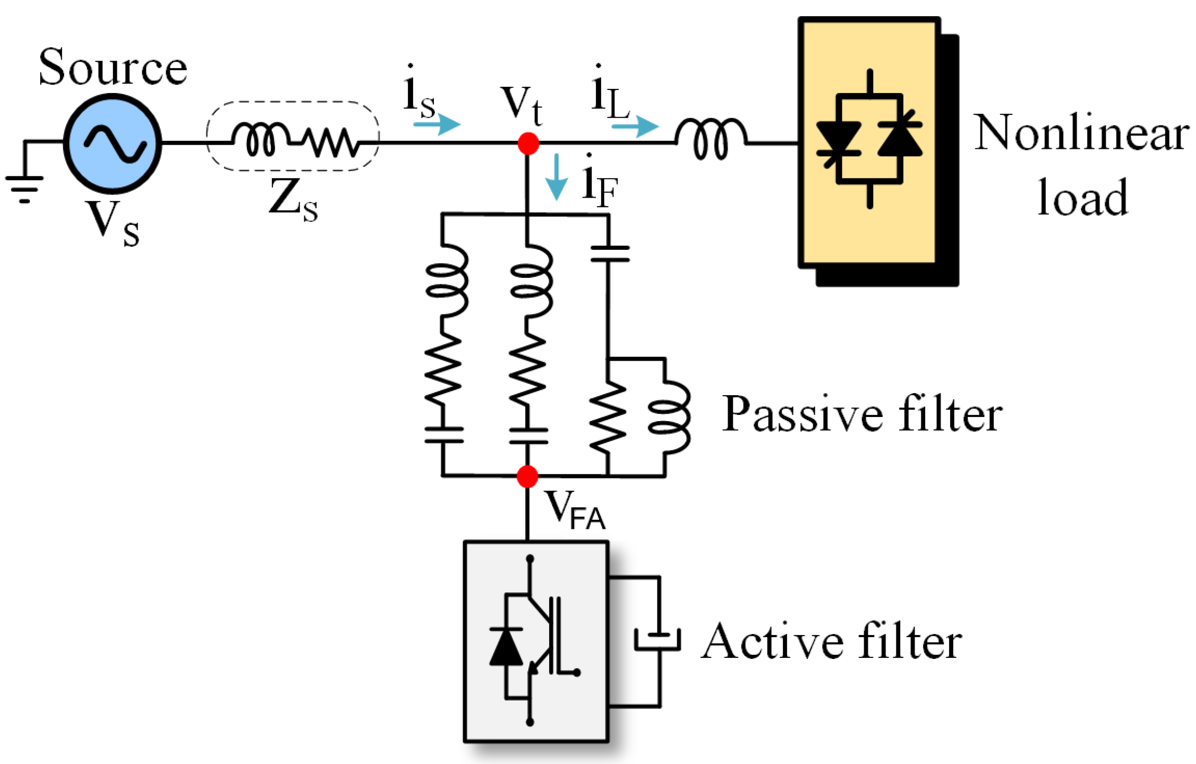
Figure 1. Series hybrid filter.
Energies 17 06019 g001
Figure 2. Parallel hybrid filter.
Energies 17 06019 g002
Figure 3. Unified Power Quality Conditioner (UPQC).
Energies 17 06019 g003
Figure 4. Single-line diagram of the power system under study.
Energies 17 06019 g004
Figure 5. Single-line diagram of the hot strip mill’s electrical system divided in blocks.
Energies 17 06019 g005
Figure 6. Electrical system of hot strip mill in Matlab/Simulink®.
Energies 17 06019 g006
Figure 7. Back-to-back hybrid filter.
Energies 17 06019 g007
Figure 8. Control diagram of the series hybrid filter.
Energies 17 06019 g008
Figure 9. Control diagram of the parallel hybrid filter.
Energies 17 06019 g009
Figure 10. DC bus voltage control.
Energies 17 06019 g010
Figure 11. Block diagram of the harmonic detection method.
Energies 17 06019 g011
Figure 12. (a) Configuration 1: Series active filter near the source. (b) Configuration 2: Parallel active filter near the source.
Energies 17 06019 g012
Figure 13. (a) Configuration 1: Series active filter located close to the source. (b) Configuration 2: Parallel active filter near the source.
Energies 17 06019 g013
Figure 14. Transfer function of the equations found by technique 4: (a) ish/iLh; (b) iFh/iLh.
Energies 17 06019 g014
Figure 15. Transfer functions of appropriate techniques: (a) ish/iLh; (b) iFh/iLh.
Energies 17 06019 g015
Figure 16. Back-to-back hybrid filter model implemented in Simulink®.
Energies 17 06019 g016
Figure 17. Composition of the back-to-back hybrid filter implemented in Simulink®.
Energies 17 06019 g017
Figure 18. SRF control: (a) series active filter; and (b) parallel active filter.
Energies 17 06019 g018
Figure 19. Line voltage at PCC: (a) Voltage waveform. (b) Harmonic spectrum without filter. (c) Harmonic spectrum with back-to-back hybrid filter.
Energies 17 06019 g019
Figure 20. Line current at PCC: (a) Current waveform. (b) Harmonic spectrum without filter. (c) Harmonic spectrum with back-to-back hybrid filter.
Energies 17 06019 g020
Figure 21. Line current in passive filter: (a) Voltage waveform. (b) Harmonic spectrum without filter. (c) Harmonic spectrum with back-to-back hybrid filter.
Energies 17 06019 g021
Figure 22. Voltage and current of the series active filter for technique 4.
Energies 17 06019 g022
Figure 23. Voltage and current of the parallel active filter—technique 4.
Energies 17 06019 g023
Table 1. Comparison of harmonic mitigation techniques.
TechniquePerformanceAdvantagesDisadvantagesCost
Passive Filters [32,33,34]Moderate
  • Simple construction and low maintenance
  • Cost-effective for known harmonics
  • Limited to specific harmonics, potential for resonance issues
  • Less effective for variable harmonic profiles
Low
Active Filters [35,36,37]High
  • Mitigates a wide range of harmonics
  • Adapts to load changes, addresses interharmonics
  • High initial and operational cost
  • Consumes more power and uses complex control systems
High
Hybrid Filters [12,18]High
  • Combines strengths of passive and active filters
  • Cost-effective with broad harmonic mitigation
  • More complex design and installation
  • Requires initial investment and expertise
Moderate
Table 2. The electrical system’s main nominal power.
CharacteristicsCapacity
Power source—34.5 kV75 MVA
Rolling mils (cycloconverters)63 MVA
High-pass filter (2.6 HP)—156 Hz10 Mvar
Band-pass filter (4.08 BP)—244.8 Hz10.8 Mvar
High-pass filter (6 HP)—360 Hz12.5 Mvar
High-pass filter (10 HP)—600 Hz12.3 Mvar
Table 3. Overview of the results of the techniques applied to the back-to-back hybrid filter.
TechniqueSeries ( K v )Parallel ( K a )Appropriate
1 i s h i s h YES
2 i s h i F NO
3 i s h i L h YES
4 i s h i L h YES
5 i F i s h NO
6 i F i F NO
7 i F i L h NO
8 i F i L h YES
9 i L h i s h NO
10 i L h i F NO
11 i L h i L h NO
12 i L h i L h NO
13 i L h i s h NO
14 i L h i F NO
15 i L h i L h NO
16 i L h i L h YES
Table 4. Current in the branches of the passive filter bank using the back-to-back hybrid filter, specifically by applying technique 4.
Filtering SystemNominal Value (A)Current (A)
Passive filter-734.67
 High-pass filter —156 Hz (2.6 HP)167160.76
 Band-pass filter—244.8 Hz (4.08 BP)181174.27
 High-pass filter—360 Hz (6 HP)209203.58
 High-pass filter—600 Hz (10 HP)206205.91
Table 5. Current values in the passive filter branches according to the techniques applied.
Filtering SystemNominal
(A)
Tec. 1
(A)
Tec. 3
(A)
Tec. 4
(A)
Tec. 8
(A)
Tec. 16
(A)
Passive filter736.54734.07734.67732.28731.85
High-pass filter—156 Hz167160.74160.67160.76160.90160.72
Band-pass filter—244.8 Hz181174.97173.98174.27173.58173.63
High-pass filter—360 Hz209205.71203.00203.58200.69201.10
High-pass filter—600 Hz206210.29205.76205.91198.10198.79
Power active filter series (MVA)1.412.451.670.2580.619
Power parallel active filter (MVA)3.383.383.5714.3013.80
Total: ( | S F A S | + | S F A P | ) (MVA)4.835.835.2414.5614.42
Table 6. Comparative analysis of voltage and current THD between the techniques applicable to the back-to-back hybrid filter.
TopologyPCC Voltage
[%]
PCC Current
[%]
Passive Filter Current
[%]
Passive Filter2.943.0118.12
Tec. 11.532.2111.70
Tec. 31.281.589.88
Tec. 41.231.789.02
Tec. 80.700.702.99
Tec. 160.720.622.93
Table 7. Comparison of THD reduction for voltage and current at the PCC, and passive filter current compared to the passive filter solution.
TechniquePCC Voltage Reduction [%]PCC Current Reduction [%]Passive Filter Current Reduction [%]
Tec. 147.9626.5835.42
Tec. 356.4647.5145.48
Tec. 458.1640.8650.23
Tec. 876.1976.0883.49
Tec. 1675.5179.4083.83
Table 8. Current values in the passive filter branches and nominal capacity of the active filters in the hybrid topologies: back-to-back, series, and parallel.
CurrentNominal
[A]
Back-to-Back
[A]
Series
[A]
Parallel
[A]
Passive filter-734.67731.88732.04
High-pass filter—156 Hz167160.76159.87160.81
Band-pass filter—244.8 Hz181174.27173.27173.56
High-pass filter—360 Hz209203.58202.88200.73
High-pass filter—600 Hz206205.91209.37198.20
Power active filter series [MVA]1.672.7-
Power parallel active filter [MVA]3.57-12.68
Table 9. Comparative analysis of voltage and current THD between hybrid topologies: back-to-back (tec. 4), series, and parallel.
TopologyPCC Voltage
[%]
PCC Current
[%]
Passive Filter Current
[%]
Without hybrid filter2.943.0118.12
Series hybrid filter1.391.6811.86
Parallel hybrid filter0.310.502.32
Back-to-back hybrid filter1.231.789.02
Disclaimer/Publisher’s Note: The statements, opinions and data contained in all publications are solely those of the individual author(s) and contributor(s) and not of MDPI and/or the editor(s). MDPI and/or the editor(s) disclaim responsibility for any injury to people or property resulting from any ideas, methods, instructions or products referred to in the content.