1. Introduction
Electrodynamic forces often occur in high-current circuits during the flow of short-circuit current. Accurately determining the electrodynamic load for current paths in residual current circuit breakers (RCCBs) is a complex task for scientists. Analytical results are often approximate due to the need for simplifications in calculations. The calculations for individual current paths depend on understanding the allowable bending stresses of the materials used in the circuit sections. To determine the moments and electrodynamic forces on the current paths, scientists use the Biot–Savart, Lorentz, and Maxwell equations. Maxwell’s equations help calculate electrodynamic forces in systems where the inductance can be expressed analytically. In contrast, the Lorentz and Biot–Savart equations are generally used for calculating the electrodynamic moments and forces on the straight segments of current paths. In designing current paths for RCCBs, it is crucial to focus on the necessary calculations related to the following:
Stresses arising in the primary current path of the RCCB during short-circuit currents should be considered, which will allow for the selection of suitable circuit cross-sections, span lengths, and the correct fastening of current paths.
Moments affecting moving parts, such as the moving contacts of RCCBs, both in the closed position and during the occurrence of short-circuit currents upon switching, are crucial to consider.
Considering the reaction forces exerted on fastening elements and other brackets securing the current paths enables the selection of suitable insulators with the necessary strength and the determination of the quantity of these elements required (
Figure 1).
Forces acting on the electric arc should also be considered.
Conducting these calculations presents considerable challenges, and errors can easily result in inaccurate outcomes. In analytical calculations, various parameters need to be established, including the following:
The distribution of electrodynamic stress along the current path;
The resultant force acting on the specific current path;
The moment generated by the resultant force;
The point of the resultant force application.
Traditional analytical methods lack the precision needed to calculate the primary current path of RCCBs accurately. Instead, current calculation practices rely on finite element analysis (FEA) techniques, utilizing 3D structural models for the precise mapping and calculation of electrodynamic forces within every element of the RCCB structure. This study focuses on validating numerical FEA using COMSOL 6.1 Multiphysics software to accurately determine the electrodynamic forces in the main current path of the RCCB. The present research is structured as follows:
Section 1—short-circuit tests of RCCBs were performed to record real short-circuit current waveforms in the short-circuit laboratory.
Section 2—simulation part, which, with the use of advanced numerical analyses, allowed for the analysis of electrodynamic forces in the primary current paths of the residual current circuit breaker.
2. The State of the Art
The literature includes research on the interactions of electrodynamic forces in various devices and current path systems. The covariant formulation of Maxwell’s equations according to [
1] summarizes the fundamentals of electricity and magnetism. This book explains the basics of special relativity and then applies the covariant formulation to analyze and understand electrodynamic phenomena.
In [
2,
3,
4], the authors describe the use of QuickField software to develop numerical models for analyzing low- or medium-voltage three-phase rectangular busbar systems under steady-state and short-circuit conditions. This study employs a magnetic harmonic model combined with a steady-state thermal model to determine the thermal field distribution for the rated current. Additionally, by integrating the steady-state thermal model for the rated current with a magnetic model for short-circuit current and a transient thermal model, the authors have the possibility to predict the time-dependent temperature distribution during short-circuit events. This study also uses a transient magnetic model to calculate electrodynamic forces. Different configurations of busbar systems are examined, including arrangements with one or more conductors per phase.
In [
5], the authors explore the impact of electrodynamic forces on tulip contact systems used in high-voltage circuit breakers. These circuit breakers typically feature two tulip contact systems. One system functions as the arcing contact, constructed from tungsten-coated elements which minimize the effect of arc erosion. The other system consists of one or two crown contacts. The arcing contact system is a single, massive component designed to maximize the contact surface area. In contrast, the crown contact system is made up of multiple smaller contacts to enhance the contact area and reduce transition resistance. Validating electrodynamic forces through dynamic measurements poses a significant challenge due to the unique operational conditions of circuit breakers. To overcome this, the authors propose using the finite element method (FEM) for a detailed 3D-coupled simulation to calculate the electrodynamic forces acting on the contact system. The simulation results offer important insights into how these contact systems perform under short-circuit conditions.
In [
6], the authors utilize a 3D finite element model to examine the contact system of a circuit breaker equipped with an oil dashpot. Specifically, they focus on analyzing two electrodynamic repulsion forces: the Holm force between contacts and the Lorentz force between conductor arms. By studying the current density distribution, magnetic intensity distribution, and forces acting on the contact and its arm, they obtain valuable insights. Comparing the obtained results with theoretical values, the authors demonstrate the feasibility of using this method to accurately calculate electrodynamic repulsion forces. They proceeded to analyze the main factors affecting the Holm force, analyzing its variations with different surface contact coefficients, contact pressures, and material hardness. Moreover, the authors optimize the structure of the contact system using ANSYS software. This optimization enhances the electrodynamic repulsion force, particularly in short-circuit conditions, thereby aiding the circuit breaker equipped with an oil dashpot in effectively breaking the circuit.
In [
7], the authors investigated the impact of electrodynamic forces on current paths within industrial distribution switchgear. The study comprised experimental and simulation sections. In the experimental segment, short-circuit tests were conducted, showcasing the visible interactions of electrodynamic forces. The emergence of these forces in the current circuits of power distribution systems was attributed predominantly to the flow of high currents, particularly during short-circuit events. This paper elucidated the parameters involved in these tests to underscore the significance of these phenomena. Transitioning to the simulation section, the authors employed a detailed real-scale model of switchgear and current paths to capture the physical phenomenon of electrodynamic forces. To achieve this, they advocated for the utilization of the FEM to derive the values of electrodynamic forces through meticulous 3D-coupled simulations. The ensuing analysis of the simulation results and their consequential effects yields interesting insights into the operation of such power distribution configurations, especially under critical short-circuit conditions.
The authors in [
8] address the issue of high electromagnetic forces induced in the current paths of low-voltage electromagnetic relays due to fault currents in electrical installations. These forces can trigger an electromagnetic bounce, leading to electric arc ignition between contacts and potentially resulting in contact welding. To ensure the reliable operation of relays, it is crucial to determine the threshold value of the maximum current and, consequently, the electrodynamic force. This paper presented the results of calculations and experiments on electromagnetic forces, encompassing these influencing factors. Both a static closing force acting on the contacts and the fault current were measured. Consequently, the values of the force and current threshold were derived, providing insights into when an electrodynamic bounce may occur. These findings can be instrumental in designing contact rivets and relay current paths, as well as in selecting appropriate fault protection devices, to ensure optimal relay performance and prevent potential damage.
In [
9], the authors emphasize the significance of the short-time withstand current (Icw) as a critical parameter for air circuit breakers (ACBs), particularly in terms of selective protection. To comprehensively analyze the short-circuit dynamic stability of a three-phase ACB, the authors take into account factors such as the skin effect, interphase effect, and nonlinear B-H characteristics of ferromagnets. To achieve this, the authors adopt a 3D transient finite element method. The analysis involves calculating transient current, repulsion torque, tilting torque, and sliding torque on each movable conductor at both the initial and periodic stages of Icw. It is observed that electromagnetic torque causes the outer movable conductors to tilt and slide towards the middle of each phase. Notably, the conductors of phase B exhibit the poorest dynamic stability. In addition to simulation, experiments were conducted to further investigate dynamic stability. These experiments involve observing the position, size, and sliding trace of erosion marks on contact tips. Based on the proposed calculation model, it is determined that installing ferromagnet plates on both sides of movable conductor groups can effectively enhance dynamic stability. This insight offers valuable guidance for optimizing the design and performance of ACBs, ensuring reliable operation under short-circuit conditions.
The authors of [
10] explore the innovative modeling technology known as the digital twin in the context of simulating physical phenomena. This paper presents, validates, and discusses a digital twin model focused on electrodynamic forces in a three-phase high-voltage disconnector. Laboratory work and the measurements of electrodynamic forces highlight the significant challenges: the research process is often arduous and costly, and obtaining accurate measurements of electrodynamic forces in real-world conditions is nearly impossible, even with modern computing machines. Consequently, the use of advanced field models reduced to a simpler reduced-order model (ROM) through digital twin technology gave the authors a promising solution, enabling significant advancements in this research area. The proposed modeling approach by the authors facilitates the extraction of results from complex models, including those needed for long-term thermal tests. The outcomes of the digital twin model are compared and validated against data from short-circuit tests conducted in the laboratory.
In [
11], the authors emphasized the critical role and unique position of generator circuit breakers (GCBs) in electric power systems. GCBs must be designed and manufactured to endure extremely high short-circuit currents multiple times throughout their lifetime. Therefore, an accurate and efficient method for conducting coupled electromagnetic–mechanical simulations of a GCB in its full geometric complexity as the authors proposed is essential for design processes. This paper detailed a novel method for integrating electromagnetic and dynamic mechanical analyses for GCBs. The proposed method in this research was fast, accurate, efficient, robust, and well suited for handling highly complex 3D geometries.
In [
12], the authors demonstrated that the interrupting characteristics of low-voltage current-limiting circuit breakers are directly influenced by the magnitude and distribution of the magnetic field generated by the contact system and splitter plates. To assess the impact of the contact system configuration on current limiting characteristics, a 3D magnetic field analysis of the arc chamber (including the contact system, arc, and splitter plates) was performed. Additionally, the electromagnetic repulsion force acting on the movable contact was calculated. The findings can be used to enhance the design of the arc quenching chamber. The authors also analyzed the interaction between the operating mechanism and the electromagnetic repulsion force.
In [
13], the authors highlighted that the short-time withstand current (Icw) is a crucial parameter for air circuit breakers (ACBs) and can easily lead to electrodynamic stability issues. This paper investigated the effects of the closing phase angle and frequency on the electrodynamic stability of ACBs. By considering the skin effect, interphase effect, and the nonlinear B-H characteristics of ferromagnetic materials, a calculation model of a three-phase ACB was developed using the 3D transient finite element method. This study found that movable conductors exhibit the poorest electrodynamic stability when the closing phase angle (ψ) is equal to φ − π/2, φ + π/6, and φ + 5π/6, where φ represents the phase angle difference between the voltage and the current. As the frequency increases, the peak currents and repulsion forces in selected phases shift to a slope-shaped distribution. Additionally, the peak lateral forces on the movable conductors adjacent to other phases significantly increase with rising frequency.
In [
14], the authors combined experimental studies on three-terminal silicon carbide (SiC) NEMSs with a theoretical investigation to elucidate the origin of the electrostatic double-layer force (EDF) and the Casimir effect, which led to stiction, and to develop a stiction mitigation design. The authors indicated that finite element modeling and analytical calculations demonstrate that the EDF becomes dominant over the elastic restoring force in such SiC NEMSs when the switching gap shrinks to a few nanometers, resulting in irreversible stiction at contact.
One of the most significant challenges [
15] is the repulsive force between contact members caused by both the current path shrinking near the actual contact area and the so-called pinch effect. This issue is particularly problematic for power switch applications, leading to either contact floating or bouncing, which are associated with electric arcs following contact welding. In this paper, the authors presented an approach to determining the electrodynamic force value for different shapes (rectangular, square, circle, and arch) of copper plates used in a compensator using ANSYS for a current value of 40 kA RMS. Curve-fitting was performed based on the calculation results, and the optimization of the compensation unit design was derived from these results.
In [
16], the authors highlight that electrical contacts are an essential part of many electrical appliances, among which are circuit breakers or electromagnetic relays. For their long-term usage, heat distribution, during normal operation, is a key factor. The heat generated is relative to both the current value and electrical contact resistance. A numerical simulation conducted in this research using a specialized scientific program was used to observe heat distribution in electrical contacts. This simulation was conducted based on real electrical contact data used in electromagnetic relays.
The authors of [
17] examine an electrodynamic compensator for high-current contacts, wherein the free end of the inactive contact, integrated into the compensator’s design with contact pads, is bent 180 degrees towards the axis of rotation of the inactive contact. This design modification reduces the shoulder on which the electrodynamic repulsion force of the contacts acts. Consequently, the repulsion moment of the contacts is also decreased, thus simplifying the fulfillment of the condition for their full compensation. This paper provides formulas for calculating the additional electrodynamic force of the compensator under consideration and its contour coefficient. Calculations of the additional electrodynamic effort of the breaker compensator are conducted for a rated current of 630 A with a short-time withstand current of 40 kA.
The authors of [
18] introduce two methodologies, namely, an analytical and a numerical approach, designed to assess electrodynamic forces in switching devices featuring intricate circuit configurations. The analytical method serves as a preliminary design tool, enabling the swift evaluation of electrodynamic forces acting on current-carrying conductors. Conversely, the numerical tool functions as a validation model, assessing forces generated by currents and flux densities using a 3D finite element method. These methodologies are applied herein to comprehensively analyze an earthing switch tailored for railway applications. The numerical findings are presented to substantiate the efficacy of the proposed methodologies.
The findings presented in [
19] likely demonstrate the efficacy of utilizing 3D FEA to evaluate and potentially optimize the design of contact systems in low-voltage AC switching devices. This advancement could lead to the improved performance, efficiency, and reliability of such devices in practical applications.
In [
20], the authors introduce a dynamic analysis method for determining the repulsion forces exerted on current-carrying contacts. This method involves computing the dynamic repulsion forces by integrating the 3D finite element method (FEM) with magnetic field analysis, current distribution analysis, and the motion analysis of contacts. The efficacy of this method was demonstrated through a dynamic analysis of the repulsion forces on contacts.
In [
21], the authors present a 3D transient finite element method (FEM) for analyzing the short-time withstand current of an air circuit breaker (ACB). They utilized a cylindrical contact bridge to model the current constriction between movable and fixed contacts. The analysis took into account the influence of eddy currents, variations in resistivity and thermal conductivity with temperature, and the coupled calculation of the electromagnetic and thermal fields. To verify the accuracy of their calculation method and results, the authors conducted relevant experiments. They measured the temperature at two points on the contacts using thermocouples. The experimental results confirmed that the proposed method is effective. The authors demonstrated that their method can be used to optimize the design of ACBs, ensuring improved performance and reliability.
In [
22], the authors develop a finite element model of a stationary contact pair incorporating a contact bridge for electromagnetic-coupled field analysis. Through simulation, they investigate how the shape and size parameters of a single-contact bridge affect the electrodynamic force. Additionally, they compare and analyze the impact of the number and distribution positions of multiple-contact bridges on the electrodynamic force. This study reveals that in the single-bridge case, the repulsion force is highly dependent on the perimeter of the contact a-spot. In the case of multiple-contact bridges, the total electrodynamic force is significantly influenced by the spots distributed in the outermost ring. This detailed analysis helps in understanding the relationship between contact geometry and electrodynamic forces, which can inform the optimization of contact bridge designs for better performance.
In [
23], the authors explore dimension reduction to enhance energy efficiency for onboard applications. They validate the capability of an earthing switch, as an electromechanical device, to withstand electrodynamic forces. Two approaches are applied and compared using a simplified three-dimensional (3D) model of the earthing switch. The first approach is analytical: electrodynamic forces are calculated under the assumption that currents flow in concentrated lines, and the maximum static stress is compared to the yield point of the earthing knife material. The second approach uses the finite element method in the time domain to analyze these forces. The results indicate that a rectangular cross-section can endure the electrodynamic forces generated by the specified currents. Additionally, a simple cost analysis demonstrates the material savings achieved by redesigning the standard earthing knives from a C channel profile to a rectangular profile. These savings make this study particularly relevant for marine switchgear applications, highlighting both the technical feasibility and economic benefits of the new design.
In [
24], the authors present a coupled electric–magnetic thermal–mechanical analysis of busbar systems under short-circuit currents. This comprehensive analysis is conducted using the finite element method, which allows for a detailed modeling of the interactions among various physical phenomena. The authors discover that the type of busbar support significantly influences the displacement of the conductors during short-circuit currents. Although the temperature rise resulting from short-circuit current flows is analyzed, it is found to have only a slight impact on the displacement of the busbar conductors. This study highlights the importance of support structures in the design of busbar systems to ensure stability and performance under fault conditions.
The theoretical analysis of insulating contact systems presented by the authors in [
25] aims to assess the diversity of electric fields in contact gaps. The primary objective is to identify areas within the switch that exhibit the highest sensitivity to breakdown. This involves determining the specific features that are particularly crucial for ensuring electric strength. By understanding these critical areas and features, this study seeks to enhance the reliability and performance of insulating contact systems in switching devices.
In [
26], the authors perform analytical calculations on an asymmetric three-phase busbar system. They calculate key parameters such as the maximum value of electrodynamic forces, mechanical strength, and the natural frequency of the busbar. These calculations are validated using an ANSYS model of a parallel asymmetric busbar system, which confirmed the results obtained from the analytical calculations. This study demonstrates that a finite element model is highly useful in selecting and optimizing unusually shaped busbars for various electrotechnical applications, including switchgear.
In [
27], the authors develop a model to determine the peak current required to weld closed contacts. The model takes into account several factors:
- -
Total Contact Resistance: This includes both the expected constriction resistance and the resistance due to the high temperature at the contact spot.
- -
Blow-off Force: The force generated by the passage of current through the contact spot, which can influence the contact dynamics.
- -
Reduction in Hardness: The decrease in the hardness of the contact metal caused by the high temperature at the contact spot.
The model’s predictions generally align with experimental values within the uncertainty range of the material data provided in the data tables of standard contact materials. This suggests that the model is reliable and can be used to estimate the peak current needed for welding closed contacts accurately.
The authors of [
28] introduce a modern computer modeling method for analyzing low-voltage extinguishing chambers used in modular apparatuses. The focus is on demonstrating the phenomenon of increasing the blow-out effect by using ferromagnetic plates to divide the electric arc within the electrical apparatus. The authors present an advanced tool for analyzing physical phenomena inside the extinguishing chamber. This tool enables the examination of how changes in the geometry and materials of the components affect the process of switching off the current. This approach can be applied to analyze physical phenomena in devices handling both alternating current (AC) and direct current (DC). This versatility makes this method valuable for improving the design and functionality of various electrical apparatuses.
In [
29], the authors present a 3D finite element method approach to simulating the transient thermal behavior of substation connectors. The proposed multiphysics method includes both the connector and the reference power conductors in its simulations. This method is validated against experimental data, showing that the transient and steady-state temperature profiles of both the conductors and connectors predicted by the finite element method are accurate. Experimental validation is performed using short-circuit tests in two high-current laboratories. The results demonstrate that the finite element method is both suitable and precise for modeling the thermal behavior of substation connectors. This simulation tool is particularly useful during the design and optimization phases of substation connectors, as it can predict the outcomes of mandatory laboratory tests, thereby streamlining the design process and improving efficiency.
It is evident from the research presented that dealing with three-phase short-circuit currents as two-phase currents from an analytical perspective, particularly in electrodynamic standards, can lead to challenges. These challenges include the need for time-consuming and labor-intensive tests in short-circuit laboratories, as well as discrepancies between prototype and final product performance. One significant aspect highlighted is the scarcity of dedicated test systems for assessing electrodynamic forces in design or accredited laboratories. In response to these challenges, the authors of this publication focused on analyzing physical phenomena related to the flow of short-circuit currents, specifically targeting electrodynamic forces.
By using real waveforms obtained from short-circuit laboratory tests, the authors conducted advanced simulations, considering the prototype of the residual current circuit breakers, electrical contacts, and the primary current path during short-circuit tests. This approach likely provides valuable insights into the behavior of these systems under realistic conditions, aiding in the design and optimization process while mitigating the limitations associated with experimental tests.
3. Simulation Section
To conduct the simulation work for this manuscript, a coupled finite element analysis was performed. This technique enables the study of interactions among various physical phenomena, including structural, mechanical, and electromagnetic effects. The analysis involves linking different nodes within a numerical program to meet specific conditions and simulate physical phenomena digitally, providing a preview of the outcomes before the actual experiment is completed. The coupled analysis relies on transforming coupled partial differential equations into a set of independent ordinary differential equations using the modal decomposition technique. This process allows the system to be expressed as a linear combination of its modes, which represent the characteristic patterns of vibration or oscillation within each domain. Modal decomposition offers a direct solution for addressing complex numerical challenges. The modal coefficients derived from this method can then be applied to simulate each domain individually. Coupled analysis provides several benefits over other FEM-based approaches to solving coupled problems. These benefits include handling nonlinearities and variable material properties; accounting for mechanical interactions, energy dissipation, and inter-domain energy transfer; understanding the physical mechanisms and dominant modes of the system; and reducing computational costs and memory requirements.
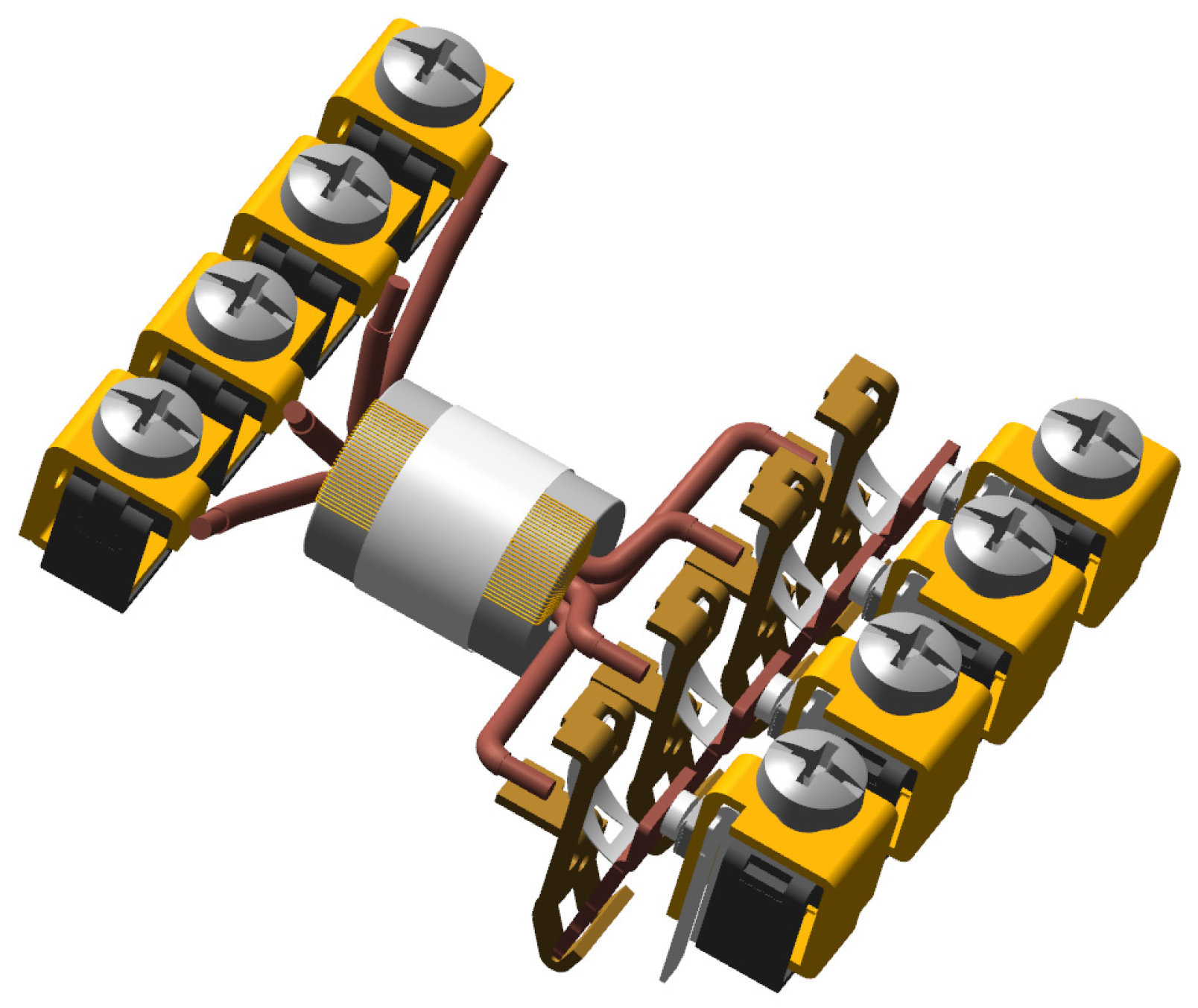
After conducting short-circuit tests at the ICEM Laboratory in Maribor, Slovenia, simulation analyses were performed to compare with the experimental results obtained. To carry out these numerical analyses, a detailed 3D model of the tested RCCB was created. The model was developed using Creo 10.0 software, accurately replicating all components of the RCCB’s structure, with some simplifications for parts such as housings, supports, insulators, the current paths, the Ferranti transformer, and others, as depicted in
Figure 2 below.
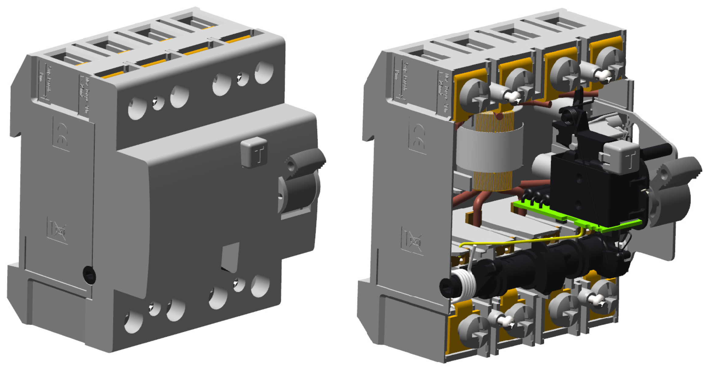
This model was prepared to align with the short-circuit tests of the RCCB’s primary current paths. The geometries created in this way were imported into the COMSOL Multiphysics environment, as shown in
Figure 3 below.
After importing the 3D models into the COMSOL Multiphysics software, the electrical load profile was imported, which outlines the current conditions under various operational scenarios, and integrated into COMSOL Multiphysics. This load profile was essential for simulating the electrodynamic forces generated within the RCCB, as it provides the necessary data to replicate real operating conditions.
A careful selection of material properties, with particular emphasis on relative permeability, was then undertaken to accurately represent the magnetic behavior of the RCCB components. These material properties play a significant role in influencing the simulation of magnetic fields and forces within the model (
Table 1).
Following this, the relevant physical phenomena, specifically the magnetic fields, were defined within the simulation environment. This involved setting up the magnetic field equations and boundary conditions to capture the interactions between the electrodynamic forces and the RCCB components effectively. The fundamental equations that COMSOL Multiphysics solvers use during calculations are presented below.
Gauss law for electricity:
Gauss law for magnetism:
where
—electric induction [C/m
2];
—magnetic induction [T];
—electric field intensity [V/m];
—magnetic field intensity [A/m];
—current density [A/m
2]; ρ—electric charge density [C/m
3]; ∇—divergence operator [1/m]; ∇x—rotation operator [1/m].
The deformations of the primary current paths of the residual current circuit breaker during the performed simulations were described by Lorentz as a force that can be expressed by the following equation:
The next step was to discretize the geometry into finite elements through a process known as meshing. Special attention was given to regions where magnetic forces are the most critical, employing a fine mesh to ensure high accuracy in capturing the magnetic field distribution. The data for the prepared mesh are summarized in the table below (
Table 2).
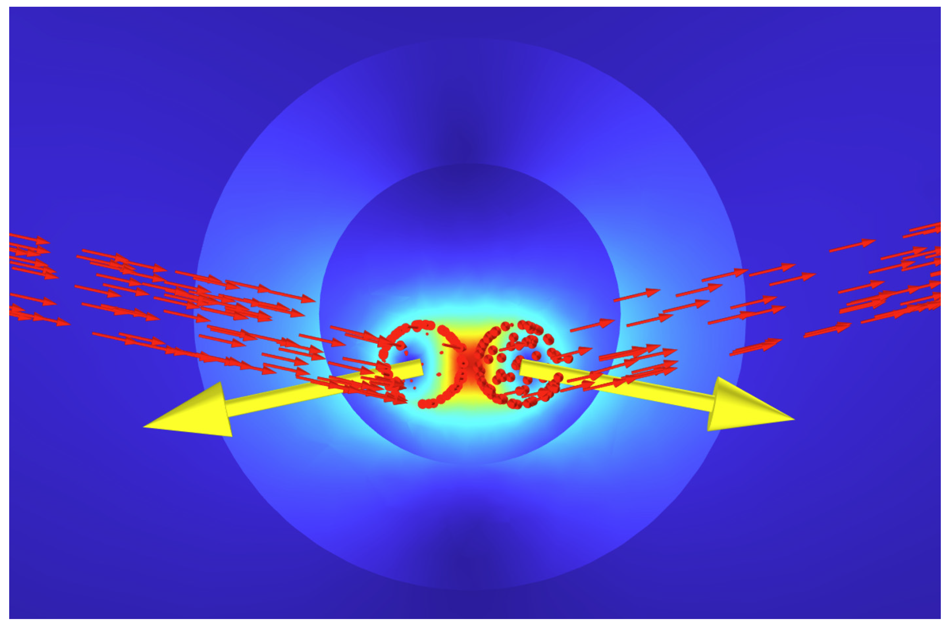
Once the model was fully configured, the simulation was performed to solve the magnetic field equations under the specified load conditions. This computational process provides detailed insights into the distribution and magnitude of the electrodynamic forces acting on the RCCB components, as shown in
Figure 4 below.
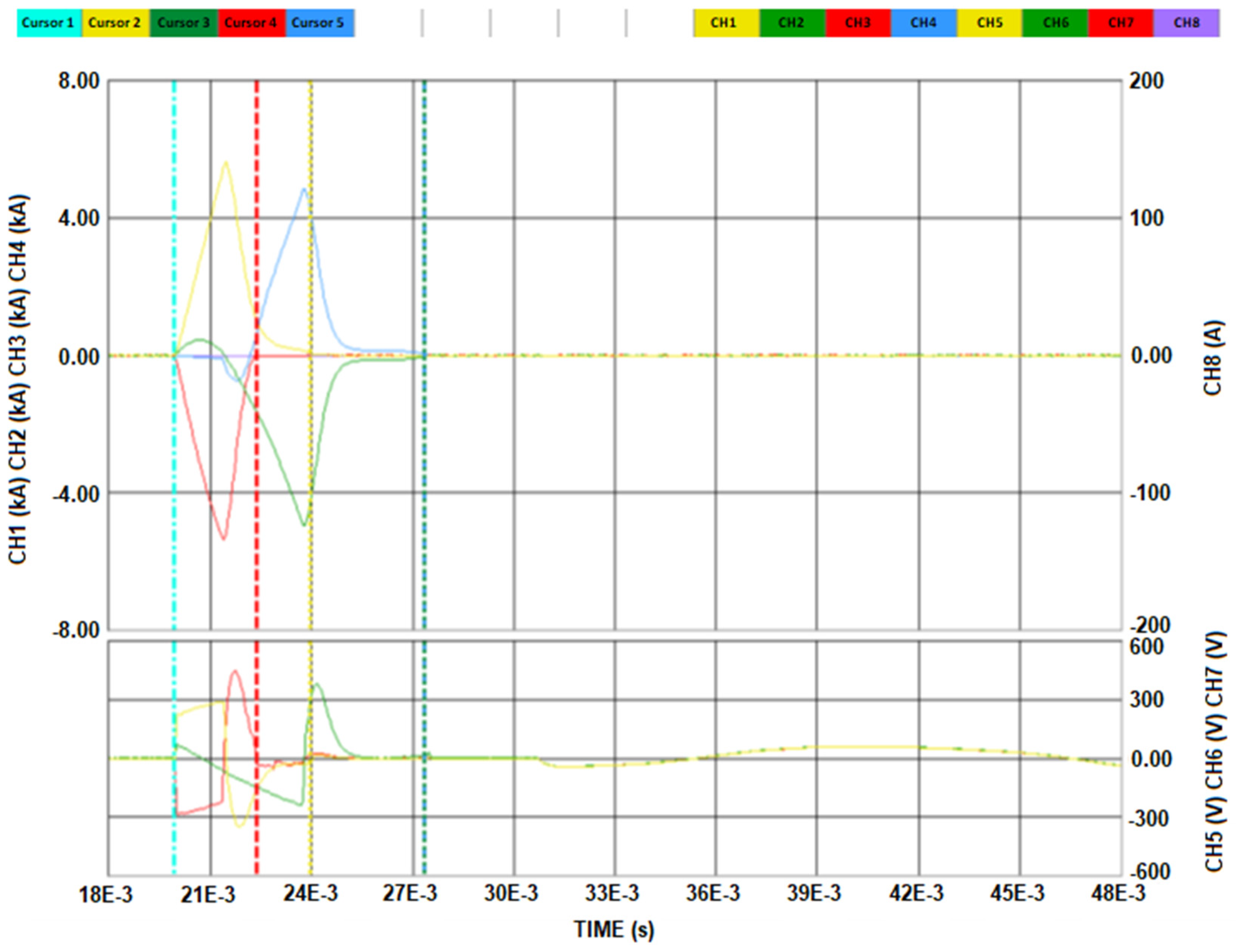
The short-circuit current values for each phase, prepared in this analysis, were then assigned to the corresponding RCCB current paths, mirroring the conditions of the actual short-circuit tests. The imported short-circuit currents for phase L1 and the N terminal are depicted in the waveform plotted from the software, as shown in
Figure 5 below.
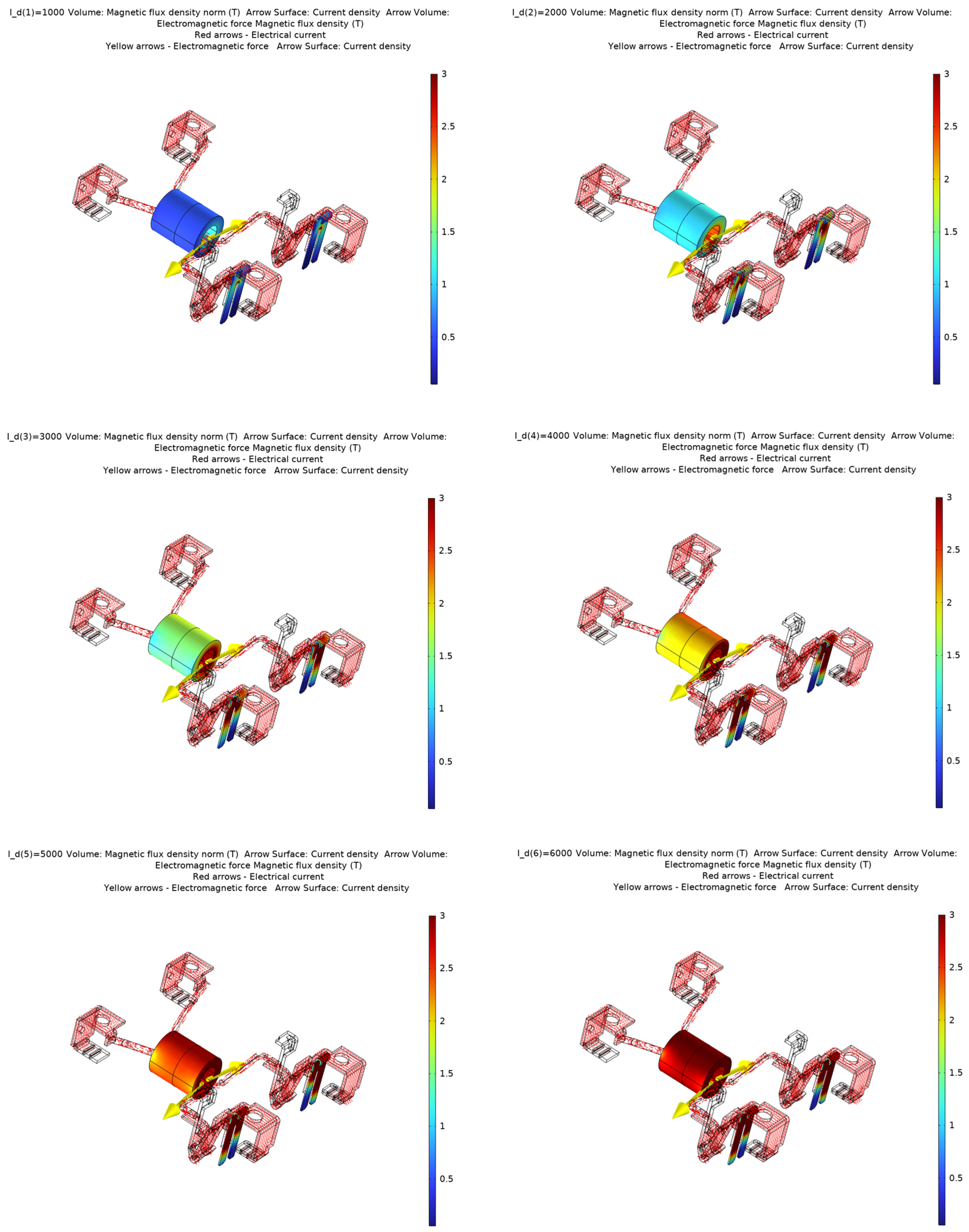
The values of magnetic flux density in the core and between phase L1 and the N terminal were dependent on the value of the current, which was plotted by software, as shown in
Figure 6 below.
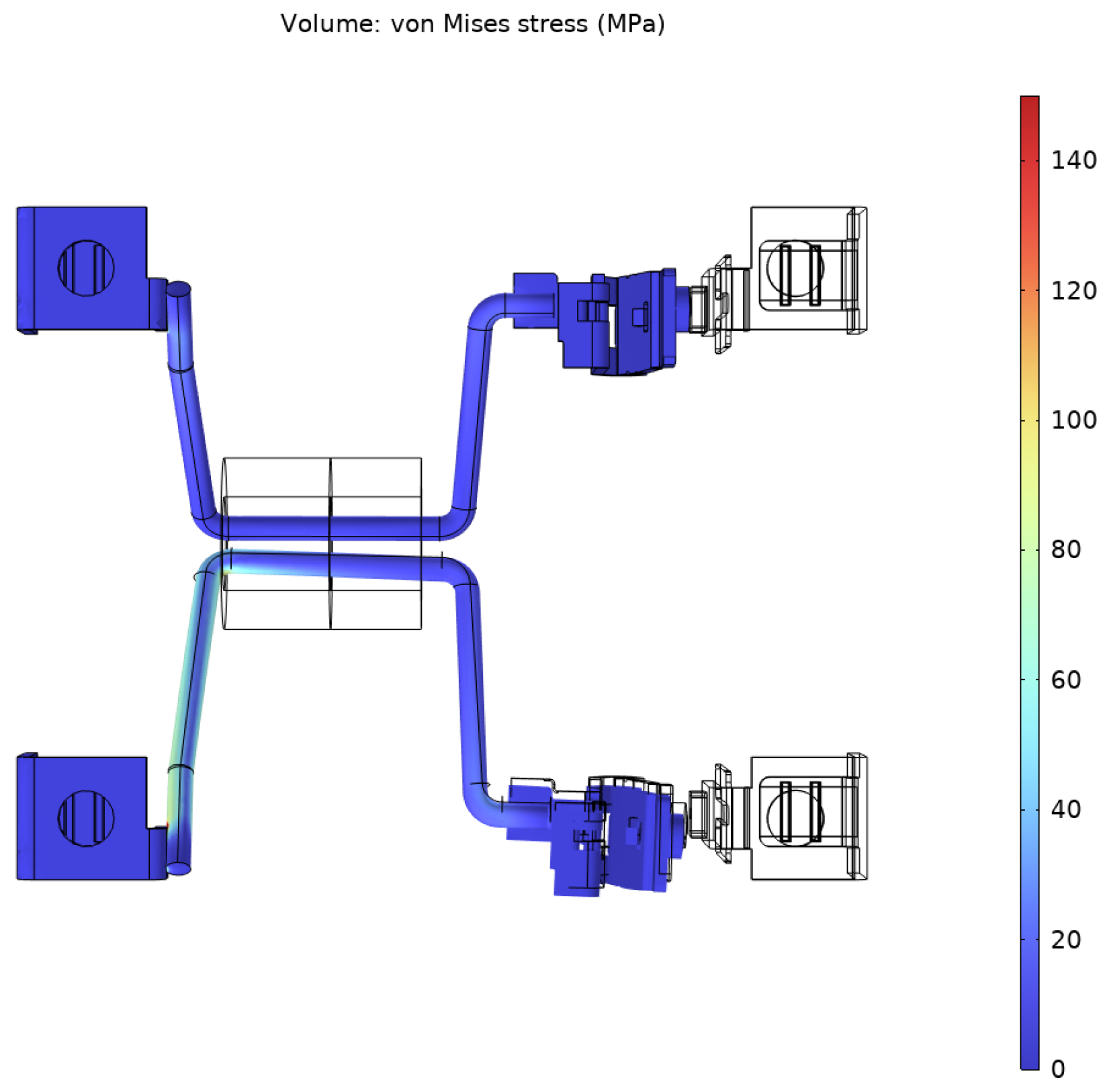
The simulation results were analyzed to assess the magnitude and distribution of these electrodynamic forces in the RCCB. This analysis was essential for identifying areas that may be prone to mechanical stress or displacement due to the forces generated. The results allowed for the analysis of stresses and strains in the tested current path of the residual current circuit breaker between the L1 and N poles. For this purpose, “von Mises stress” was generated for the most stressed locations in the current path. The highest stress values were generated at the current path attachment points, i.e., near the welding points to the top terminals of the circuit breaker and the movable contact supports. An example of a selected time point is shown in
Figure 7 below.
Another factor confirming the high level of correlation between the simulation and experimental results was the deformation of the tested current path of the residual current circuit breaker between the L1 and N poles. This correlation is illustrated in
Figure 8 below.
Finally, the numerical model was prepared for validation. This involved setting up comparable experimental tests aimed at correlating the simulation results with real data. The goal was to confirm the accuracy and reliability of the model, ensuring its applicability for future analyses and design optimizations.


