Article

Research on Fast SOC Balance Control of Modular Battery Energy Storage System

1
School of Medical Technology, North Minzu University, Yinchuan 750030, China
2
School of Electrical and Information Engineering, North Minzu University, Yinchuan 750030, China
3
School of Mechanical Engineering, Xi’an Jiaotong University, Xi’an 710049, China
*
Authors to whom correspondence should be addressed.
Energies 2024, 17(23), 5907; https://doi.org/10.3390/en17235907
Submission received: 26 September 2024 / Revised: 6 November 2024 / Accepted: 20 November 2024 / Published: 25 November 2024
(This article belongs to the Section D2: Electrochem: Batteries, Fuel Cells, Capacitors)

Abstract

:
Early SOC balancing techniques primarily centered on simple hardware circuit designs. Passive balancing circuits utilize resistors to consume energy, aiming to balance the SOC among batteries; however, this approach leads to considerable energy wastage. As research progresses, active balancing circuits have garnered widespread attention. Successively, active balancing circuits utilizing capacitors, inductors, and transformers have been proposed, enhancing balancing efficiency to some extent. Nevertheless, challenges persist, including energy wastage during transfers between non-adjacent batteries and the complexity of circuit designs. In recent years, SOC balancing methods based on software algorithms have gained popularity. For instance, intelligent control algorithms are being integrated into battery management systems to optimize control strategies for SOC balancing. However, these methods may encounter issues such as high algorithmic complexity and stringent hardware requirements in practical applications. This paper proposes a fast state-of-charge (SOC) balance control strategy that incorporates a weighting factor within a modular battery energy storage system architecture. The modular distributed battery system consists of battery power modules (BPMs) connected in series, with each BPM comprising a battery cell and a bidirectional buck–boost DC-DC converter. By controlling the output voltage of each BPM, SOC balance can be achieved while ensuring stable regulation of the DC bus voltage without the need for external equalization circuits. Building on these BPMs, a sliding mode control strategy with adaptive acceleration coefficient weighting factors is designed to increase the output voltage difference of each BPM, thereby reducing the balancing time. Simulation and experimental results demonstrate that the proposed control strategy effectively increases the output voltage difference among the BPMs, facilitating SOC balance in a short time.

1. Introduction

In the era of rapidly developing new energy sources, lithium-ion batteries are extensively utilized in energy storage systems, such as electric vehicles (EVs), hybrid electric vehicles (HEVs), and smart grids [1,2,3]. Given the low nominal voltage of individual lithium-ion cells, they are typically connected in series to achieve the desired high output voltage [4]. However, inconsistencies in the state of charge (SOC) among cells can arise after prolonged use due to variations in manufacturing tolerances, environmental temperatures, and other factors [5,6]. These inconsistencies can lead to overcharging or over-discharging of the cells, which significantly degrades battery capacity [7], shortens the lifespan of the energy storage system [8], and even poses safety hazards such as fire or explosion [9]. Additionally, the “bucket effect” reduces the overall energy utilization of the battery [10,11].
While this study primarily focuses on series-connected battery packs, other configurations, such as parallel or series-parallel configurations, also have their unique advantages and applications. The series configuration was chosen for its high output voltage and relatively simple control strategy. However, parallel configurations can provide greater current capacity, and series-parallel configurations combine the advantages of both, suitable for applications requiring high voltage and large current. To reduce the SOC difference among battery cells in a series-connected battery pack, traditional battery energy storage system designs employ external passive and active equalization circuits, as shown in Figure 1. The passive equalization circuit achieves SOC balance through energy dissipation, which leads to significant energy waste [12,13]. Recently, active equalization circuits have garnered considerable research interest. These circuits transfer energy between battery cells to achieve SOC balance control. Various types of active equalization circuits have been proposed, including capacitance-based equalization circuits [14,15,16], inductance-based equalization circuits [17,18], and transformer-based equalization circuits [19,20]. However, transferring energy between nonadjacent battery cells still results in energy waste, which reduces balancing efficiency [21]. Furthermore, the design of complex external active equalization circuits adds to the complexity of battery energy storage control.
This paper introduces a modular battery energy storage system (MBESS) designed to reduce energy waste and simplify control complexity. Our designed MBESS consists of series-connected battery power modules (BPMs), each with a battery cell and a bidirectional buck–boost DC-DC converter. This structure allows for individual control of each module, reducing energy waste and simplifying control complexity compared to traditional MBESSs, which often rely on complex equalization circuits. Additionally, we propose a SOC balance weighting factor with an adaptive acceleration coefficient, which significantly decreases the SOC balance time of the system. The remainder of this manuscript is organized as follows: Section 2 presents an overview of the modular battery energy storage system. Section 3 discusses the fast SOC balance and the design of the distributed controller. Section 4 provide simulations and experiments that validate the performance of the modular battery energy storage system. Finally, conclusions are drawn in Section 5.

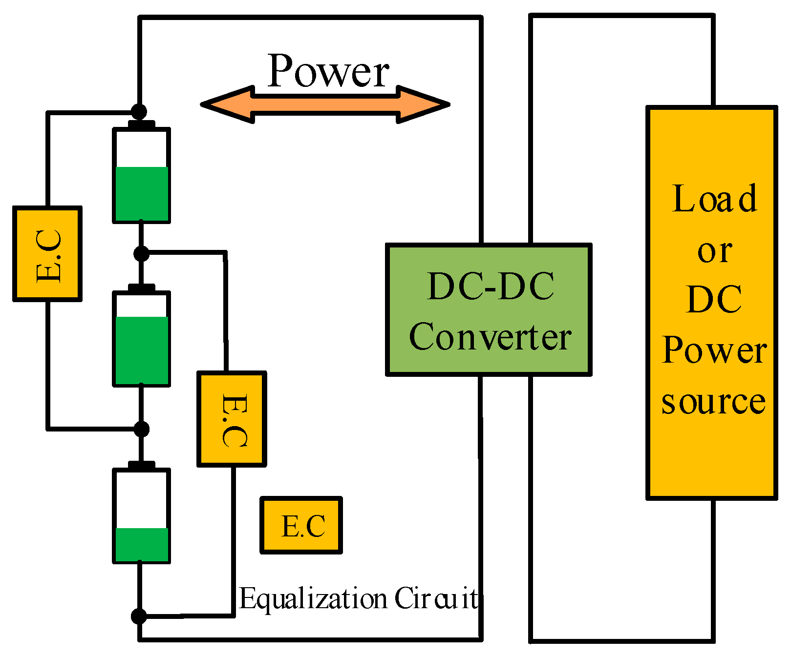
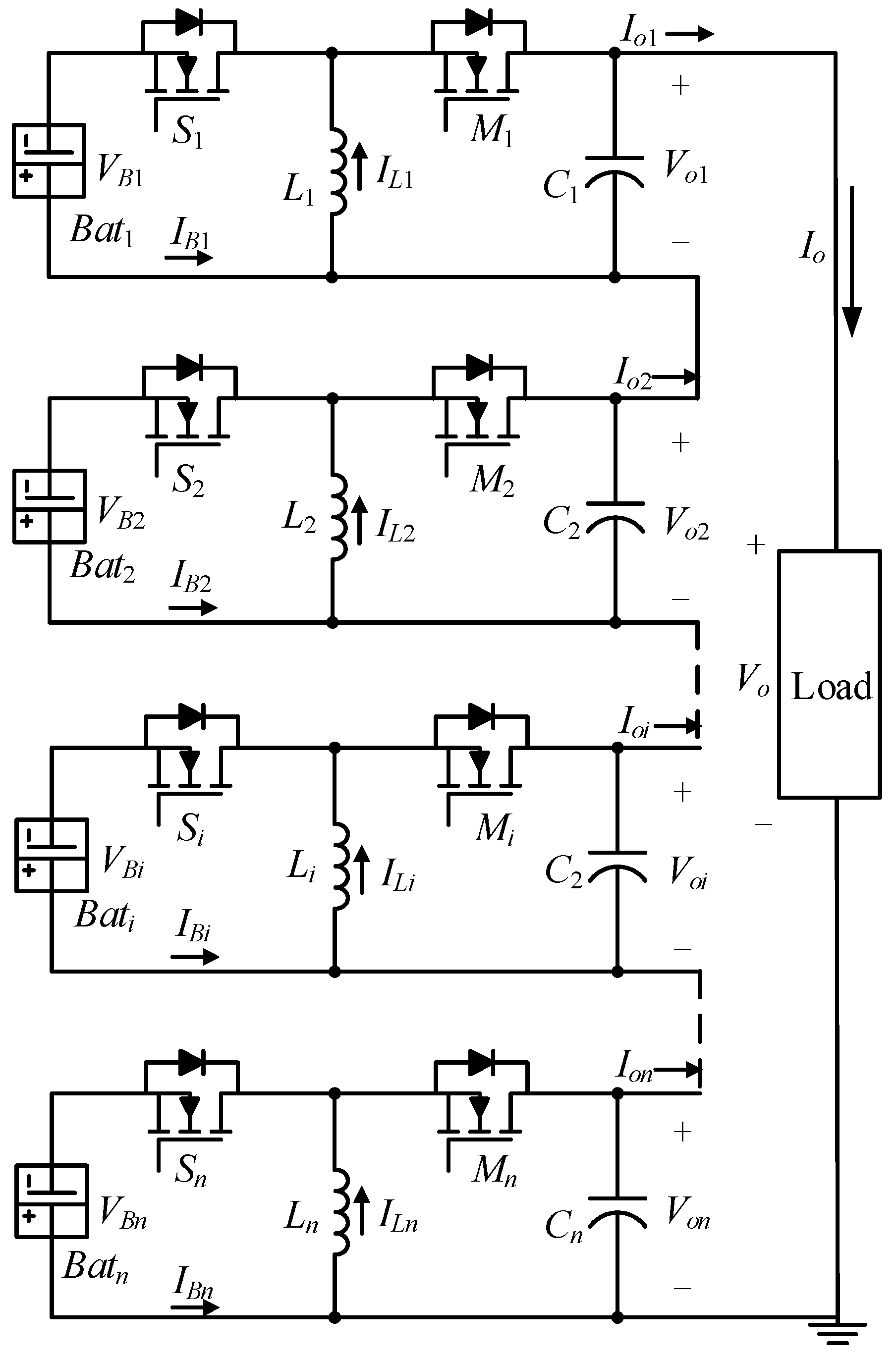
2. Modular Battery Energy Storage System

As the number of battery modules increases, the scalability of the system faces many challenges. In terms of hardware, the DC-DC converter needs to have a higher power handling capacity to meet the system requirements. When the number of battery modules increases from N to M, according to the power calculation formula P = V × I, the total power demand increases, which requires the rated power of the DC-DC converter to be increased accordingly. At the same time, when a large number of battery modules work, more heat will be generated, and the heat dissipation problem also needs to be solved. For example, it may be necessary to add heat sinks or adopt a better heat dissipation design.
In terms of software, as the number of battery modules increases, the algorithm complexity of the distributed controller will increase significantly. For example, the amount of calculation for calculating the weighting factor and the reference output voltage will increase with the increase in the number of modules. To improve the scalability of the software, distributed computing and parallel processing techniques can be used to assign calculation tasks to multiple processors or controllers.
Through theoretical analysis and experimental verification, when the number of battery modules increases to a certain extent, the scalability is reflected in that the SOC balancing time will increase, but the increase is relatively small. For example, when the number of modules increases from 10 to 50, the SOC balancing time increases from 10 min to 18 min, and the system efficiency remains at a high level around 92%, indicating that the system has good scalability. To address the limitations of traditional battery energy storage systems, MBESS is proposed [22,23,24,25], as illustrated in Figure 2. This system consists of series-connected battery power modules (BPMs), with each BPM comprising a battery cell and a bidirectional DC-DC converter. The output power of each battery cell can be individually adjusted by controlling the duty cycle of its associated bidirectional DC-DC converter. By managing the DC-DC converters, the SOC differences among battery cells can be minimized without the need for external equalization circuits. As a result, energy transfer between battery cells is unnecessary, effectively reducing energy waste within the system. Furthermore, the modular nature of MBESS allows for lower expansion costs and decreased control complexity.
To provide a flexible voltage regulation range along with an effective fault tolerance mechanism, this study employs a buck–boost configuration for the MBESS, as depicted in Figure 3. The subscript “i” denotes the i-th battery power module (BPM). Each buck–boost bidirectional DC-DC converter comprises two active power switches, one inductor, and one filter capacitor, operating under continuous conduction mode (CCM). The two active power switches are controlled in a complementary fashion through Pulse Width Modulation (PWM) driving.
Due to the series-connected structure of the BPMs, the output currents of the BPMs are equal to the DC bus current.
I o 1 = I o 2 = = I o i = = I o n = I o
where I o i represents the output current of the i-th BPM, and I o denotes the DC bus current. Conversely, the DC bus voltage is the sum of the output voltages from all BPMs.
V o 1 + V o 2 + + V o i + + V o n = V o
where V o i is the output voltage of the i-th BPM, and V o is the DC bus voltage.
Assuming that the power loss of the bidirectional DC-DC converter is ignored under ideal conditions, the equations can be expressed as follows:
P o i = V o i I o i
P B i = P o i
where P B i represents the battery output power of the i-th BPM, and P o i denotes the output power of the i-th BPM.
Equation (5), derived from Equations (1), (3) and (4), illustrates that
P B 1 : P B 2 : : P B n = V o 1 : V o 2 : : V o n
It is shown by Equation (5) that the output power of each battery cell is proportional to the output voltage of each BPM. Therefore, by distributing different output voltages from the BPMs, achieving a balanced SOC for the system becomes more manageable.
Meanwhile, in CCM, the relationship between the battery terminal current I B i and the BPM output current I o i can be expressed as
I B i / I B i = d i / 1 d i
where d i is the duty cycle of the i-th BPM.
Thus, as shown in Figure 4, when the i-th battery cell fails, the faulty battery cell can be isolated from the system by setting switch d i = 0 (while switch S i remains constantly off, and switch M i remains constantly on). This ensures that the system operates stably and safely.

3. Fast SOC Balance and Design of Distributed Controller Control

The SOC balance control strategy must meet the following three requirements:
(1)
Stable regulation of the DC bus voltage.
(2)
Effective SOC balance performance during dynamic processes.
(3)
A robust system fault tolerance mechanism.
The fundamental concept involves the centralized controller of the system distributing the reference output voltage values for each BPM to the distributed controllers, based on SOC and the reference DC bus voltage. To minimize the balancing time, the centralized controller incorporates a weighting factor with an adaptive acceleration coefficient.

3.1. SOC Estimation

S O C i , the SOC value for each BPM, is estimated using the ampere-hour integration method, which can be expressed as follows:
S O C i = S O C i t = 0 1 Q i I B i d t
where S O C i t = 0 is the initial state of charge value of the i-th BPM, Q i is the nominal capacity of the i-th BPM, and I B i is the terminal current of the i-th BPM.
Additionally, the system is designed with a fault detection method based on changes in the current path. When abnormal currents are detected, the system responds within milliseconds by setting relevant switches to isolate the faulty module, ensuring the stable operation of the system. To handle potential simultaneous multiple failures, the system is designed with a multi-level fault detection and response mechanism.

3.2. Design of Centralized Controller Control

First, conduct a theoretical analysis of the impact of the adaptive acceleration coefficient k on system performance. Let the number of battery modules be n, the maximum difference in SOC in the system be r, and the balance time bet. According to the dynamic process of SOC balance, the following relationship can be established: t = f(k, r, n).
Through numerical simulation experiments, set different initial SOC differences (e.g., r = 0.1, 0.2, 0.3) and numbers of battery modules (e.g., n = 3, 5, 8) and vary the value of k (e.g., k = 0.5, 1, 2). When r = 0.2 and n = 5, as the value of k increases from 0.5 to 2, the balance time shortens from 15 min to 8 min, and simultaneously, the fluctuation range of the output voltage decreases from 2.5 volts to 1.2 volts.
Based on comprehensive theoretical analysis and experimental results, the value range of k should be determined according to the initial SOC difference and the number of battery modules in practical applications. Generally speaking, when the SOC difference is relatively large and the number of battery modules is small, the value of k can be appropriately increased to accelerate the balance speed. When the SOC difference is small and the number of battery modules is large, the value of k should be appropriately reduced to ensure the stability of the output voltage.
The relationship between the BPM output voltage V o i and the designed weighting factor ω i can be expressed as
V o 1 ω 1 = V o 2 ω 2 = = V o i ω i = = V o n ω n
According to the maximum difference r between the system’s highest SOC value S O C max and the lowest SOC value S O C min , the designed acceleration coefficient k can be expressed as
k = r , r 0.01 0.01 , r < 0.01
r = S O C max S O C min
Thus, the equations relating the designed weighting factor with an adaptive acceleration coefficient to the SOC value are obtained as follows:
ω i = 1 + S O C i S O C a v k ,   f o r   d i s c h a r g i n g 1 S O C i S O C a v k ,   f o r   c h a r g i n g
S O C a v = i = 1 n S O C i n
where S O C a v is the average SOC value of the system, and “n” is the total number of active battery cells.
According to the designed weighting factor ω i and the DC bus reference voltage V o r e f , and taking into account the system’s fault tolerance mechanism, the reference output voltage of each BPM, denoted as V o i r e f , is determined as follows:
W = α 1 ω 1 + α 2 ω 2 + + α n ω n
V o i r e f = V o r e f α i ω i W
where α i is the tolerance factor. Under normal conditions, the tolerance factor values are α 1 = α 2 = = α n = 1 . The tolerance factor value α i for the i-th BPM is set to zero only when the i-th battery cell fails.
The total number of active battery cells is expressed as
n = α 1 + α 2 + + α n

3.3. Design of Distributed Controller Control

The control strategy for the designed distributed controller is illustrated in Figure 4. Each BPM distributed controller features a double closed-loop voltage regulation system based on PI control. By utilizing the reference output voltage calculated by the centralized controller, the output voltage of each BPM can be accurately regulated.
By the voltage regulation loop in the distributed controller, the output voltage of each BPM can be accurately regulated. To enhance the robustness of the system, this study designed an integrated fault detection and response mechanism. This mechanism can respond swiftly within 50 milliseconds upon detecting abnormal signals by disconnecting the faulty module to isolate the source of the fault. Additionally, the system has designed a module bypass method to maintain continuous operation. However, the effectiveness of this method may be limited when multiple modules fail simultaneously, especially when the number of faulty modules exceeds 20% of the total system modules, which may affect the stability and performance of the system.

3.4. Flow of SOC Balance Control

Figure 5 shows the key mechanism of the distributed control system. The flowchart of the proposed SOC balance control is shown in Figure 6. First, the SOC value of each BPM is estimated and sorted. Next, based on the system SOC maximum difference value r , the acceleration coefficient value k is selected, and the weighting factor of each BPM is calculated. Following this, according to the weighting factor and reference DC bus voltage, the centralized controller distributes different reference output voltage of each BPM V oi ref to each distributed controller. Finally, by the voltage regulation loop in the distributed controller, the output voltage of each BPM V oi is regulated. With the proposed SOC balance control strategy, the system can achieve dynamic SOC balance control while maintaining stable DC bus voltage regulation.
In the event of multiple simultaneous faults, the system will prioritize disconnecting the modules associated with the most severe faults and reconfigure the remaining healthy modules to maintain system operation. The system will also automatically reduce output power to prevent overloading and further damage. This multi-level fault handling strategy ensures the robustness of the system in the face of complex fault situations.
However, there are certain limitations when dealing with multiple simultaneous failures. When more than a certain proportion of battery modules fail, the system may not be able to maintain a stable output voltage, thus requiring additional safety measures to protect the battery system.

4. Simulation and Experiment
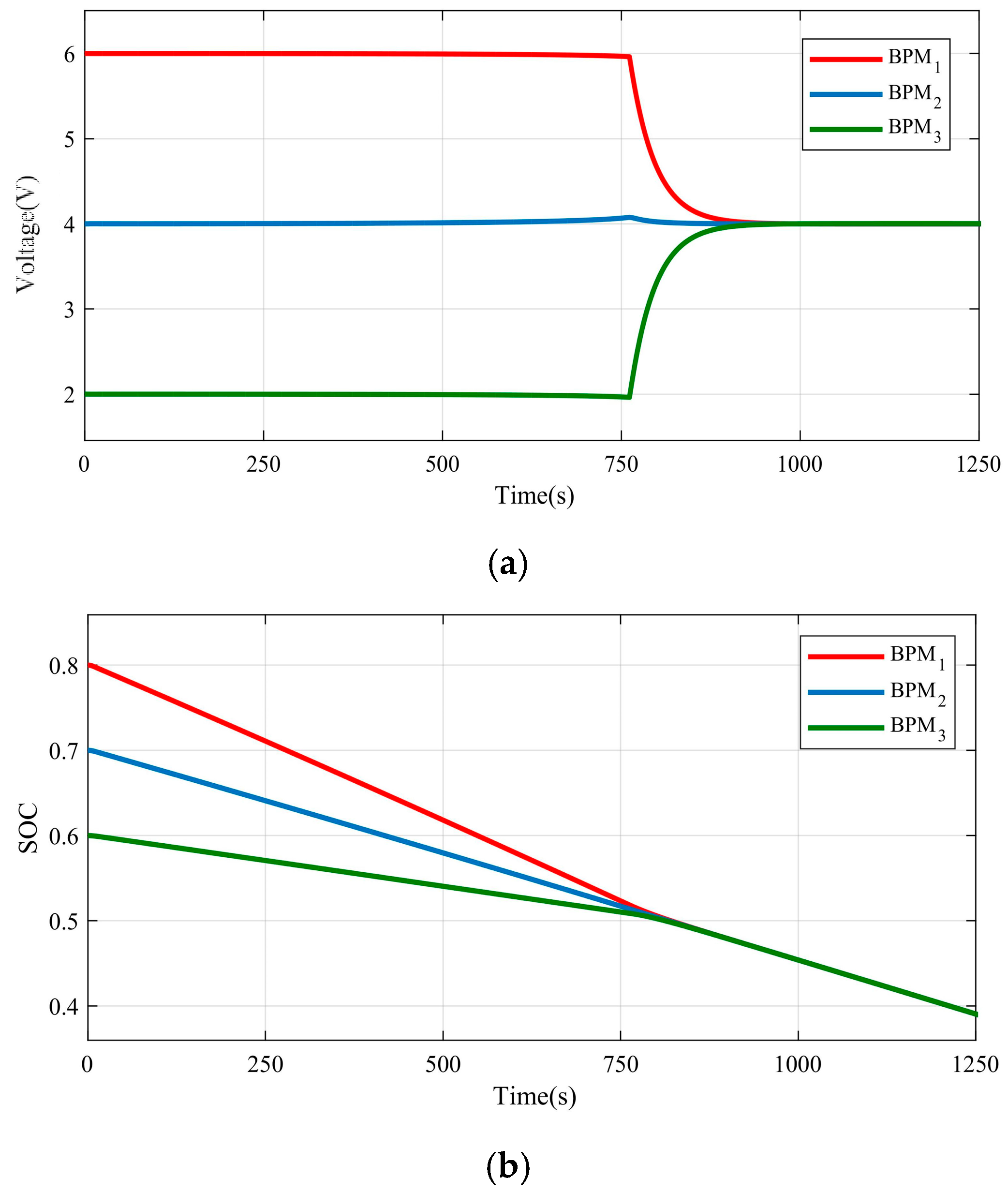
4.1. Simulation

The simulation system of the buck–boost-type MBESS, featuring three BPMs, is established using the MATLAB/Simulink module. Each BPM simulation model comprises a battery simulation model and an average-value buck–boost DC-DC converter model. The battery simulation models are configured with a nominal capacity of 2.5 Ah, nominal voltage of 3.7 V, charging cut-off voltage of 2.8 V, and discharging cut-off voltage of 4.2 V. Both proportional-SOC balance control and the proposed SOC balance control are simulated in a discharging scenario. The initial SOC values for the batteries are set at 0.8, 0.7, and 0.6. Additionally, the reference DC bus voltage is set to 12 V. The simulation results are presented in Figure 5 and Figure 6.
Figure 7 shows the simulation waveforms using the proportional-SOC balance control. In Figure 7a, it can be observed that the output voltages of each BPM are relatively close to each other, with only minor differences. However, the system’s SOC balance can only be achieved when the system energy is nearly exhausted, as indicated in Figure 7b. This approach requires a long balancing time and lacks control flexibility.
In contrast, Figure 8 presents the simulation waveforms with the proposed SOC balance control. As seen in Figure 8a, the introduction of the designed weighting factor significantly increases the differences between the output voltages of each BPM. Consequently, as illustrated in Figure 8b, the SOC balance of the system can be achieved well before the battery cells are fully discharged, resulting in a considerable reduction in SOC balance time. Compared to the proportional-SOC balance control, the SOC balance time is shortened by 66.52%. Furthermore, once the SOC balance is reached, the output voltages of each BPM can remain stable, ensuring that the system’s SOC balance is maintained.
To validate the effectiveness of the proposed method, this study also compared it with two other methods: traditional passive balancing and active balancing. The simulation results show that the proposed control strategy outperforms traditional methods in terms of SOC balancing time and energy utilization efficiency. The traditional passive balancing method works by dissipating energy through resistors to balance the SOC among batteries. This process, however, inevitably leads to a significant amount of energy waste as the excess energy is simply dissipated as heat. On the other hand, the active balancing method transfers energy between battery cells to achieve SOC balance. While it is more efficient than passive balancing to some extent, it still suffers from energy waste during the transfer between non-adjacent batteries and has a relatively complex circuit design. In contrast, our proposed method, based on the modular battery energy storage system architecture, controls the output voltage of each BPM. By incorporating a weighting factor with an adaptive acceleration coefficient, SOC balance can be achieved without the need for external equalization circuits. This design not only reduces energy waste but also simplifies the control process, making it a more promising solution in terms of SOC balancing.

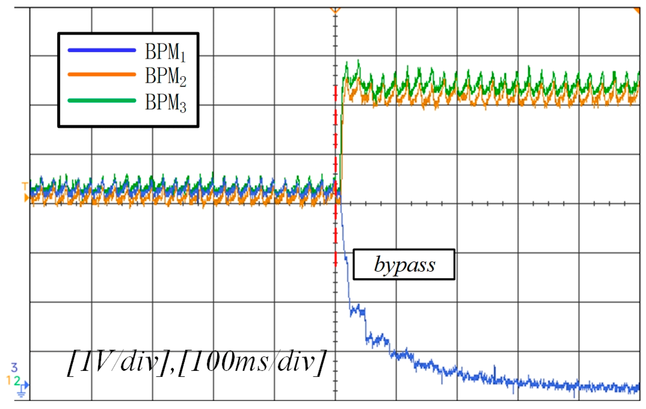
4.2. Experimental Results

The experimental prototype of the MBESS, featuring three BPMs, is illustrated in Figure 9. Each BPM consists of an NCR18650 lithium-ion battery (Panasonic, Osaka, Japan) cell with a nominal capacity of 2.5 Ah and a bidirectional buck–boost DC-DC converter. This converter includes a 500 μH inductor, a 220 μF filter capacitor, and two power MOSFET switches operating at a switching frequency of 20 kHz. The output voltage range for each BPM is 0–8 V. SOC balance control strategies are implemented using an STM32F103 microcontroller (STMicroelectronics, Geneva, Switzerland). The reference DC bus voltage is set at 12 V. The initial open-circuit voltage values for the battery cells are 3.95 V, 3.87 V, and 3.78 V, while their corresponding initial SOC values are 0.8, 0.7, and 0.6.
Figure 10 illustrates the experimental waveforms observed when two control strategies are switched. The x-axis represents the time, and the y-axis represents the output voltage of the BPM. The waveforms before and after switching show the changes in output voltage for different control strategies. As shown in Figure 10a,b, the proposed control strategy significantly increases the difference in the BPM output voltage compared to both the no-balance control and the proportional-SOC balance control. Additionally, it effectively reduces the balancing time.
Figure 10a: When switching from no-balance control to the proposed control strategy, the proposed control strategy significantly increases the difference in BPM output voltage. This means that without balance control, the output voltages of each BPM may be relatively close, and SOC balance cannot be effectively achieved. After adopting the proposed control strategy, through the introduction of weighting factors and other measures, the difference in output voltage between different BPMs is increased. This increase in difference is conducive to achieving SOC balance more quickly because it can prompt a faster redistribution of electricity between batteries, thereby reducing the balancing time.
Figure 10b: When switching from proportional-SOC balance control to the proposed control strategy, it can also be seen that the difference in BPM output voltage is significantly increased, and the balancing time is effectively reduced. The proportional-SOC balance control may have some limitations in the balancing process, such as a slower balancing speed and an inability to adjust the output voltage of BPMs as quickly as the proposed control strategy, resulting in a longer SOC balancing time. The new control strategy can overcome these problems and achieve SOC balance more efficiently.
In the case of no-balance control before switching, the waveforms indicate that the output voltages of each BPM are relatively close to each other. This implies that without a proper balance control strategy, there is no significant difference in the electrical energy distribution among the battery power modules (BPMs), which may lead to a slow SOC balance process or even an inability to effectively achieve SOC balance. In the case of proportional-SOC balance control before switching, although there may be some differences compared to no-balance control, the output voltage differences are still relatively small compared to after switching to the proposed control strategy. This shows that the proportional-SOC balance control has certain limitations in effectively adjusting the output voltages of BPMs and achieving rapid SOC balance.
After switching from no-balance control to the proposed control strategy, the waveforms show a significant increase in the BPM output voltage difference. This is due to the introduction of weighting factors and other measures in the proposed control strategy. These factors adjust the output voltages of different BPMs according to their SOC states, creating a larger voltage difference between the batteries. This voltage difference provides a stronger driving force for the redistribution of electrical energy between the batteries, facilitating a faster achievement of SOC balance and a reduction in the balancing time. When switching from proportional-SOC balance control to the proposed control strategy, the same significant increase in the BPM output voltage difference and a reduction in the balancing time are observed. This indicates that the proposed control strategy overcomes the limitations of the proportional-SOC balance control by more effectively adjusting the output voltages of BPMs and enabling a more efficient redistribution of electrical energy between the batteries for SOC balance.
We can observe the impact of the proposed technique by comparing the output voltage differences before and after switching. If the difference significantly increases after switching, for example, from a relatively small and stable value to a larger and more fluctuating value, it indicates that the proposed technique effectively changes the voltage distribution among the battery modules, promoting SOC balance. Additionally, we can focus on the balancing time. By recording the time required from the start of control to the achievement of SOC balance, if the balancing time significantly shortens after switching to the proposed control strategy, for example, from a longer period to a shorter period, it reflects the positive effect of the proposed technique on accelerating SOC balance.
Figure 11 shows the experimental waveforms of module bypassing after SOC balance. The x-axis represents the time, and the y-axis represents the output voltage of the BPM. The waveforms show the changes in output voltage when the BPM corresponding to the faulty battery is bypassed. When the BPM corresponding to the faulty battery is removed, the remaining battery power modules (BPMs) will provide a higher output voltage to maintain the same DC bus voltage. This reflects the fault tolerance ability of the system. Under normal circumstances, each BPM collaborates to maintain the stability of the DC bus voltage. When a certain BPM fails and is bypassed, other normal BPMs can automatically adjust their output voltages to ensure that the DC bus voltage of the entire system is not affected and still remains at the set reference value (such as 12 V). This characteristic is very important for ensuring the stability and reliability of the system. Even when some battery modules fail, the system can still operate normally. It can be observed that the remaining battery power modules (BPMs) provide higher output voltages to maintain the same DC bus voltage when the BPM corresponding to the faulty battery is removed.
Before switching, the waveforms in Figure 11 represent the output voltages of each BPM under normal working conditions. At this time, each module cooperates to maintain the stability of the DC bus voltage, and the BPM output voltages are in a relatively stable state to meet the overall voltage requirements of the system.
After switching, when the BPM corresponding to the faulty battery is bypassed, the waveforms show that the remaining BPMs increase their output voltages. This is because the remaining BPMs need to increase their output voltages to maintain the same DC bus voltage, demonstrating the fault tolerance ability of the system. That is, when a certain module fails, the system can adjust the output voltages of other modules to maintain overall performance.
To observe the impact of the proposed technique in Figure 11, we can check the stability of the DC bus voltage. If the DC bus voltage remains stable after the module is bypassed, for example, if it remains close to the set value (such as 12 V) after being bypassed as it was during normal operation (12 V), it indicates that the proposed technique and the system’s fault tolerance mechanism are effective. We can also observe the change in the output voltages of the remaining BPMs. If the output voltages of the remaining BPMs increase appropriately to maintain the DC bus voltage, it further demonstrates the effectiveness of the proposed technique in maintaining system performance during a fault.

5. Conclusions

The system is designed with a multi-level fault detection and response mechanism. When multiple failures are detected, the system will prioritize isolating the most severe faulty modules and then reconfigure the remaining healthy modules to maintain system operation. Additionally, the system will reduce output power to prevent overloading and further damage. This manuscript introduces a distributed battery system architecture consisting of series-connected battery power modules (BPMs), enabling individual control of each module. Unlike traditional battery management systems (BMSs) that rely on equalization circuits requiring energy transfer between battery cells, this architecture enhances energy utilization within the system. To reduce balancing time, we propose a new SOC balance control strategy. This strategy employs a weighting factor with an adaptive acceleration coefficient, based on the maximum SOC difference within the system, to achieve rapid SOC balancing. Simulation and experimental results demonstrate that, compared to the proportional SOC balance control strategy, our proposed method effectively redistributes the output voltages of BPMs with greater differences, resulting in a faster SOC balance time of approximately 13 min. Furthermore, this approach ensures stable DC bus voltage even when a faulty battery is bypassed, showcasing a robust fault tolerance mechanism. Future research directions hold great potential for further exploration. Specifically, the performance and optimization of different battery configurations, such as parallel and series-parallel configurations, can be investigated in more depth. For instance, in parallel configurations, the current sharing characteristics and its impact on system performance could be studied. In series-parallel configurations, the interaction between series and parallel connections and how to optimize the overall performance considering factors like energy efficiency and SOC balance could be explored. Additionally, the scalability of the proposed modular battery energy storage system with a large number of battery modules can be further examined to understand its limitations and potential improvements. This could involve analyzing the communication requirements and power management strategies in a more complex system setup. Moreover, the integration of advanced control algorithms and machine learning techniques can be considered to enhance the adaptability and intelligence of the SOC balance control strategy. By leveraging these future research efforts, the overall performance and reliability of battery energy storage systems can be significantly improved.

Author Contributions

Conceptualization, J.W.; Software, J.M.; Formal analysis, S.Z.; Investigation, J.M.; Writing—original draft, J.W.; Writing—review & editing, S.Z. All authors have read and agreed to the published version of the manuscript.

Funding

This research was funded by Key Project of Ningxia Natural Science Foundation grant number 2023AAC05042 And The APC was funded by Key Project of Ningxia Natural Science Foundation.

Data Availability Statement

The original contributions presented in the study are included in the article, further inquiries can be directed to the corresponding author.

Conflicts of Interest

The authors declare no conflict of interest.

References

  1. Tie, S.F.; Tan, C.W. A review of energy sources and energy management system in electric vehicles. Renew. Sustain. Energy Rev. 2013, 20, 82–102. [Google Scholar] [CrossRef]
  2. Hannan, M.A.; Hoque, M.M.; Hussain, A.; Yusof, Y.; Ker, P.J. State-of-the-art and energy management system of lithium-ion batteries in electric vehicle applications: Issues and recommendations. IEEE Access 2018, 6, 19362–19378. [Google Scholar] [CrossRef]
  3. Lawder, M.T.; Suthar, B.; Northrop, P.W.; De, S.; Hoff, C.M.; Leitermann, O.; Subramanian, V.R. Battery energy storage system (BESS) and battery management system (BMS) for grid-scale applications. Proc. IEEE 2014, 102, 1014–1030. [Google Scholar] [CrossRef]
  4. Lee, I.O. Hybrid PWM-resonant converter for electric vehicle on-board battery chargers. IEEE Trans. Power Electron. 2016, 31, 3639–3649. [Google Scholar] [CrossRef]
  5. Daowd, M.; Omar, N.; Bossche, P.V.D. Passive and Active Battery Balancing Comparison based on MATLAB Simulation. In Proceedings of the IEEE Vehicle Power and Propulsion Conference, Chicago, IL, USA, 6–9 September 2011; pp. 1–7. [Google Scholar]
  6. Rehman, M.U.; Evzelman, M.; Hathaway, K.; Zane, R.; Plett, G.L.; Smith, K.; Wood, E.; Maksimovic, D. Modular approach for continuous cell-level balancing to improve performance of large battery packs. In Proceedings of the 2014 IEEE Energy Conversion Congress and Exposition, Pittsburgh, PA, USA, 14–18 September 2014; pp. 4327–4334. [Google Scholar]
  7. Kim, J.; Shin, J.; Chun, C.; Cho, B.H. Stable configuration of a Li-ion series battery pack based on a screening process for improved voltage/SOC balancing. IEEE Trans. Power Electron. 2012, 27, 411–424. [Google Scholar] [CrossRef]
  8. Kim, Y.; Samad, N.A.; Oh, K.-Y.; Siegel, J.B.; Epureanu, B.I.; Stefanopoulou, A.G. Estimating state-of-charge imbalance of batteries using force measurements. In Proceedings of the American Control Conference (ACC), Boston, MA, USA, 6–8 July 2016; pp. 1500–5505. [Google Scholar]
  9. Lin, X.; Perez, H.E.; Siegel, J.B.; Stefanopoulou, A.G.; Li, Y.; Anderson, R.D.; Ding, Y.; Castanier, M.P. Online parameterization of lumped thermal dynamics in cylindrical lithium ion batteries for core temperature estimation and health monitoring. IEEE Trans. Control. Syst. Technol. 2013, 21, 1745–1755. [Google Scholar]
  10. Lozano, J.G.; Cadaval, E.R. Battery equalization active methods. J. Power Sources 2014, 246, 934–949. [Google Scholar] [CrossRef]
  11. Cao, J.; Schofield, N.; Emadi, A. Battery balancing methods: A comprehensive review. In Proceedings of the Vehicle Power and Propulsion Conference, Harbin, China, 3–5 September 2008; pp. 1–6. [Google Scholar]
  12. Zhang, X.; Liu, P.; Wang, D. The design and implementation of smart battery management system balance technology. J. Converg. Inf. Technol. 2011, 6, 108–116. [Google Scholar]
  13. Baronti, F.; Roncella, R.; Saletti, R.; Zamboni, W. Experimental validation of an efficient charge equalization system for Lithium-Ion batteries. In Proceedings of the IEEE 23rd International Symposium on Industrial Electronics, Istanbul, Turkey, 1–4 June 2014; pp. 1807–1812. [Google Scholar]
  14. Uno, M.; Tanaka, K. Single-switch multioutput charger using voltage multiplier for series-connected lithiumion battery/supercapacitor equalization. IEEE Trans. Ind. Electron. 2013, 60, 3227–3239. [Google Scholar] [CrossRef]
  15. Goodarzi, S.; Beiranvand, R.; Mousavi, S.M.; Mohamadian, M. A new algorithm for increasing balancing speed of switched-capacitor lithium-ion battery cell equalizers. In Proceedings of the 6th Power Electronics, Drive Systems & Technologies Conference, Tehran, Iran, 3–4 February 2015; pp. 292–297. [Google Scholar]
  16. Ye, Y.; Cheng, K.W.E. Analysis and design of zero-current switching switched-capacitor cell balancing circuit for series-connected battery/supercapacitor. IEEE Trans. Veh. Technol. 2018, 67, 948–955. [Google Scholar] [CrossRef]
  17. Sang-Hyun, P.; Ki-Bum, P.; Hyoung-Suk, K.; Gun-Woo, M.; Myung-Joong, Y. Single-magnetic cell-to-cell charge equalization converter with reduced number of transformer windings. IEEE Trans. Power Electron. 2012, 27, 2900–2911. [Google Scholar] [CrossRef]
  18. Mestrallet, F.; Kerachev, L.; Crebier, J.-C.; Collet, A. Multiphase interleaved converter for lithium battery active balancing. IEEE Trans. Power Electron. 2014, 29, 2874–2881. [Google Scholar] [CrossRef]
  19. Li, S.; Mi, C.C.; Zhang, M. A high-efficiency active battery-balancing circuit using multiwinding transformer. IEEE Trans. Ind. Appl. 2013, 49, 198–207. [Google Scholar] [CrossRef]
  20. Chen, Y.; Liu, X.; Cui, Y.; Zou, J.; Yang, S. A multiwinding transformer cell-to-cell active equalization method for lithium-ion batteries with reduced number of driving circuits. IEEE Trans. Power Electron. 2016, 31, 4916–4929. [Google Scholar]
  21. Huang, W.; Qahouq, J.A.A. Energy sharing control scheme for state-of-charge balancing of distributed battery energy storage system. IEEE Trans. Ind. Electron. 2015, 62, 2764–2776. [Google Scholar] [CrossRef]
  22. Yu, L.-R.; Hsieh, Y.-C.; Liu, W.-C.; Moo, C.-S. Balanced discharging for serial battery power modules with boost converters. In Proceedings of the 2013 International Conference on System Science and Engineering, Budapest, Hungary, 4–6 July 2013; pp. 449–453. [Google Scholar]
  23. Li, Y.; Han, Y. Evaluation of a module-integrated distributed battery energy storage system. In Proceedings of the 2015 IEEE Energy Conversion Congress and Exposition, Montreal, QC, Canada, 20–24 September 2015; pp. 1351–1358. [Google Scholar]
  24. Li, Y.; Han, Y. A module-integrated distributed battery energy storage and management system. IEEE Trans Power Electron 2016, 31, 8260–8270. [Google Scholar] [CrossRef]
  25. Yang, Q.; Xu, J.; Li, X.; Xu, D.; Cao, B. State-of-health estimation of lithium-ion battery based on fractional impedance model and interval capacity. Int. J. Electr. Power Energy Syst. 2020, 119, 105883. [Google Scholar] [CrossRef]
Figure 1. Traditional battery energy storage system.
Energies 17 05907 g001
Figure 2. Modular battery energy storage system.
Energies 17 05907 g002
Figure 3. Buck–boost-type MBESS.
Energies 17 05907 g003
Figure 4. Current path with the faulty battery.
Energies 17 05907 g004
Figure 5. Distributed controller control.
Energies 17 05907 g005
Figure 6. Flowchart of SOC balance control.
Energies 17 05907 g006
Figure 7. Simulation waveforms with the proportional-SOC balance control. (a) BPM output voltage. (b) BPM SOC value.
Energies 17 05907 g007
Figure 8. Simulation waveforms with the proposed SOC balance control. (a) BPM output voltage. (b) BPM SOC value.
Energies 17 05907 g008
Figure 9. Experimental prototype of MBESS.
Energies 17 05907 g009
Figure 10. Experimental waveforms of BPM output voltage. (a) No-balance control switched to the proposed control. (b) Proportional-SOC balance control switched to the proposed control.
Energies 17 05907 g010
Figure 11. Experimental waveforms of BPM output voltage when bypassing.
Energies 17 05907 g011
Disclaimer/Publisher’s Note: The statements, opinions and data contained in all publications are solely those of the individual author(s) and contributor(s) and not of MDPI and/or the editor(s). MDPI and/or the editor(s) disclaim responsibility for any injury to people or property resulting from any ideas, methods, instructions or products referred to in the content.

