Article

A Novel LCLC Parallel Resonant Circuit for High-Frequency Induction Heating Application

1
Department of Electrical Engineering, Taizhou University, Taizhou 225300, China
2
College of Hydraulic Science and Engineering, Yangzhou University, Yangzhou 225009, China
*
Author to whom correspondence should be addressed.
Energies 2024, 17(23), 5892; https://doi.org/10.3390/en17235892
Submission received: 11 October 2024 / Revised: 13 November 2024 / Accepted: 19 November 2024 / Published: 24 November 2024
(This article belongs to the Section F3: Power Electronics)

Abstract

:
The application of induction heating power supply in the continuous production line of tinplate has garnered significant research and scholarly attention. However, the impedance matching of LC or CLC resonant circuits in the system lacks flexibility and is susceptible to overvoltage during startup. As a solution to the problem, a novel four-order LCLC parallel resonant circuit was proposed in this study for high-frequency induction heating power supply. By incorporating auxiliary inductors in parallel with CLC compensating capacitor branches, the induction heating system can operate reliably and achieve optimal load impedance matching. The equivalent circuit and mathematical model of the new resonant load were established, and the frequency characteristics of the circuit system were analyzed. Then, the parallel resonance characteristics of the new resonant circuit were comprehensively elucidated, including the quality factor, impedance characteristics, behavior of resonant current, and properties of voltage regulation. Finally, a simulation model of a high-frequency induction heating power supply was developed based on the proposed LCLC resonant circuit and compared with LC and CLC resonant circuits. The results demonstrated that the induction heating power supply system utilizing the proposed LCLC parallel resonant load exhibits superior parallel resonant characteristics, enhanced load impedance-matching flexibility, and improved output voltage stability when compared to traditional LC or CLC parallel resonant loads.

1. Introduction

Heating is a crucial component of the steel continuous production line [1,2,3]. Traditionally, steam heating has been the predominant method used. However, with increasing emphasis on energy conservation and environmental protection, efficient electric heating methods have gradually replaced steam heating [4]. Currently, there are three mainstream electric heating methods: (i) thyristor-based voltage regulation power supply [5], (ii) high-voltage variable-frequency power supply based on IGBT [6], and (iii) induction heating power supply based on electromagnetic induction principle [7,8]. The thyristor power supply is easy to implement but suffers from significant losses and can cause severe power quality issues that impact factory operations. The high-voltage variable-frequency power supply addresses the drawbacks of thyristor regulators by reducing losses and improving power quality. Additionally, it offers variable-frequency capabilities to accommodate different steel strip specifications. However, high-voltage frequency conversion heating still relies on contact-based methods which may result in uneven heat distribution and affect product quality. In contrast, the induction heating power supply utilizes a non-contact approach that ensures uniform heat distribution across the steel strip while exhibiting excellent energy-saving characteristics aligning with current demands for energy efficiency and environmental preservation. Consequently, induction heating will emerge as the primary method for metal heat treatment [9,10].
The induction heating system typically consists of three components: (i) a DC regulation system, (ii) a high-frequency inverter part, and (iii) a resonance system [11]. The high-frequency inverter and resonance sections are the key elements of the system. Among various options for the inverter part, the current source inverter (CSI) is widely adopted due to its advantages such as low-power device requirements for voltage and current, convenient current protection, easy parallel expansion, etc. [12,13]. In order to form a resonant circuit, the heating coil is commonly connected in parallel with a compensation capacitor and linked to the output of the CSI [14,15]. However, since different application environments have distinct resonant loads, ensuring impedance matching between load and system is crucial for safe and efficient operation of induction heating systems.
Impedance matching is a key part of a resonant circuit [16,17]. At present, there are two main impedance-matching methods: electromagnetic coupling [18] and electrostatic coupling [19]. Among them, the electromagnetic coupling high-frequency transformer exhibits significant losses and occupies a large volume during operation, which hinders its integration into modular designs for high-power supplies and limits its practical applications. In contrast, the high-frequency transformer is replaced by an inductor and capacitor (LC) in the electrostatic coupling scheme, which might reduce the size, cost, and design complexity of the induction heating system [20]. However, the power regulation range of LC resonance is inherently limited, and it presents challenges in terms of open-circuit fault detection and short-circuit protection [21].
In response to these challenges, many scholars and engineers have proposed new resonant circuits, such as an LLC resonant circuit, as described in reference [22], which consists of a series inductor in an LC resonant circuit. This configuration exhibits robust short-circuit immunity and offers a versatile power control mode. However, its typical application lies within voltage inverters. Recently, the CLC resonant circuit recommended in reference [23] has gained widespread adoption. The CLC parallel resonant circuit integrates a compensating capacitor into the induction coil branch of the conventional LC parallel resonant circuit, thereby establishing a compensation mode with dual capacitors. This configuration enables the adjustment of load power and frequency by manipulating the series–parallel capacitors, resulting in an expanded range for power supply output power and frequency adjustment [24]. However, in practical engineering applications, it is essential to dynamically adjust the working frequency of the induction heating power supply just above the resonant frequency, for achieving the maximum efficiency tracking and minimum switching losses. This frequency variation might cause the voltage fluctuation of the series and parallel capacitors, accordingly affecting the stable operation of the equipment. Thus, the stability and flexibility of CLC practical application still require further improvement.
As a result, a fourth-order LCLC resonant circuit is introduced in this paper, which is constructed by adding a compensation inductor to the CLC resonant circuit mentioned above, so as to enhance the stability of the output voltage of the power supply, optimizing its power control and resonant features. Although the literature [25] has also proposed an LCLC resonant circuit, its structure differs from ours. It is based on LLC and incorporates a series capacitor in the coil branch. This configuration enables sequential dual-frequency heating and facilitates better control over mid-frequency and high-frequency power waveforms; however, it necessitates the utilization of complex algorithms.
Based on the background above, the objective of this study was to propose novel LCLC resonant loads in high-frequency induction heating power supplies and conduct an in-depth theoretical analysis and modeling simulation of the parallel characteristics exhibited by the proposed circuit. Firstly, an equivalent circuit model of the LCLC parallel resonant circuit is constructed, and the frequency characteristics of the parallel resonant system are analyzed comprehensively. Based on this analysis, we examine the quality factor, impedance characteristics, resonant current characteristics, and voltage regulation characteristics of the new resonant circuit’s parallel resonance features. We also briefly analyze how auxiliary series capacitance and parallel inductance affect the system’s resonant properties. Finally, a simulation analysis was conducted on the high-frequency induction heating power supply based on parallel resonant load. The proposed LCLC resonant circuit in this study exhibits enhanced flexibility and voltage stability compared to the LC and CLC resonant circuits. This method presents a novel idea and scheme for the application of induction heating in the steel industry.

2. Materials and Methods

2.1. Main Circuit of the LCLC-Based High-Frequency Induction Heating System

The main circuit structure of the high-frequency induction heating system based on the proposed LCLC resonant load is shown in Figure 1. From Figure 1, the grid-connected thyristor phase-controlled rectifier is applied to regulate the output power of the CSI-based heating device. In the DC link, the inductor L0 and the capacitor C0 constitute a low-pass filter, and Ld is a choke inductor, which provides a constant current source for the H-bridge inverter. The middle part is a SiC MOSFET-based H-bridge inverter, which dynamically tracks the changing resonant frequency to realize the maximum power transmission and low switching losses.
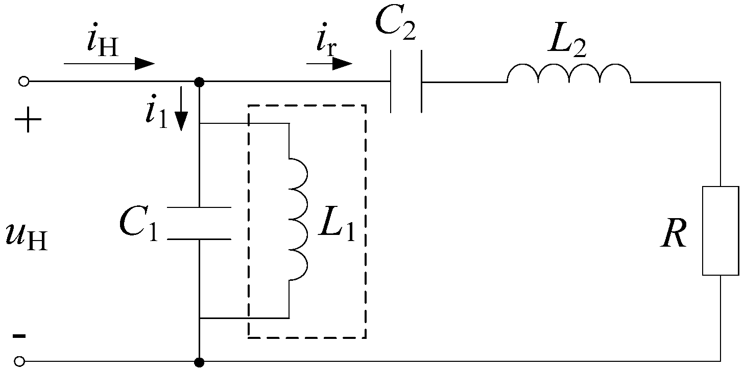
In the LCLC resonant circuit, L2 and R are the equivalent inductor of the heating coil, C1 and C2 are the compensation capacitor banks for the coil, and in particular, L1 is an auxiliary inductor in parallel with C1. Furthermore, the neutral point of the capacitor bank C1 is grounded to reduce the capacitor voltage to the ground and improve power safety. In order to enhance the reliability of the system in practical engineering applications, the inductance capacitor energy storage components are composed of several modules in series or parallel.

2.2. Frequency Characteristic of the LCLC Resonant Circuit

According to Figure 1, the equivalent circuit model of the LCLC resonant load can be illustrated in Figure 2, where the inductor L2 and resistance R in series are the equivalent impedance of the heating coil and workpiece combination. Obviously, it is a fourth-order circuit system due to the added inductor L1.
In light of Figure 2, the input admittance of the LCLC resonant circuit can be obtained as
G = j ω C 1 1 ω L 1 + 1 j ω L 2 1 ω C 2 + R
It is known that the imaginary part of the admittance equals zero under resonance condition, that is
ω C 1 1 ω L 1 × R 2 + ω L 2 1 ω C 2 2 ω L 2 1 ω C 2 = 0
In view of that, the load equivalent resistance (R) is generally small in practice, the item R2 may be negligible, and the solution of Equation (2) can be deduced as
ω 1 = 1 L 2 C 2 ω 2 = L 1 C 1 + L 2 C 2 + L 1 C 2 Δ 2 L 1 L 2 C 1 C 2 ω 3 = L 1 C 1 + L 2 C 2 + L 1 C 2 + Δ 2 L 1 L 2 C 1 C 2
Δ = L 1 C 1 + L 2 C 2 + L 1 C 2 2 4 L 1 L 2 C 1 C 2 = L 1 C 1 L 2 C 2 + L 1 C 2 2 + 4 L 1 L 2 C 2 C 2 > 0
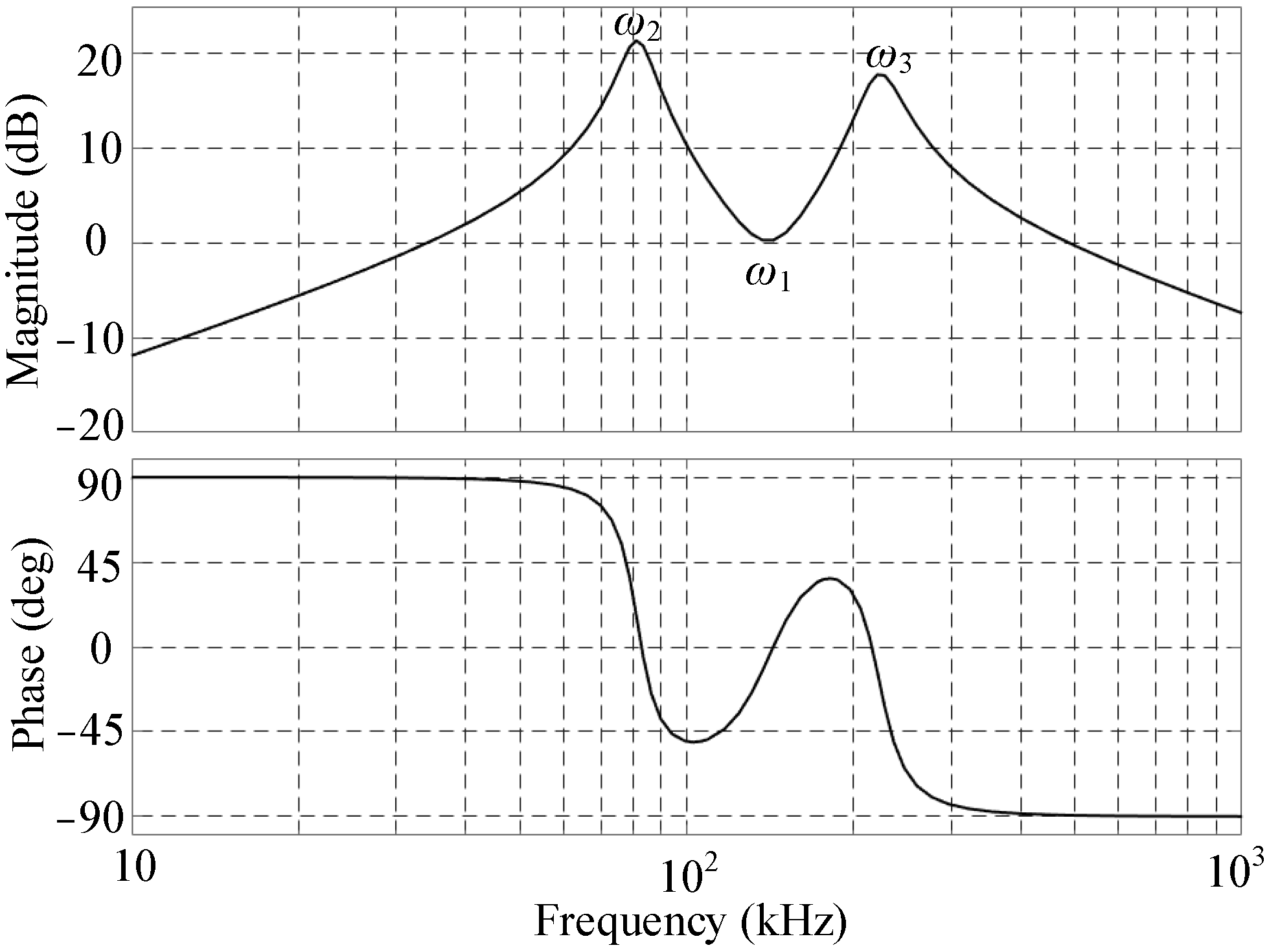
Further analysis of Equation (3a) reveals the existence of three resonant frequency points, namely ω1, ω2, and ω3. It is worth noting that the relation of these frequencies follows ω2 < ω1 < ω3 based on Equations (3a) and (3b). When the working frequency (ω) of the induction heating device is equal to ω1, RLC series resonance occurs in the branch of the induction coil. Correspondingly, the load impedance reaches the minimum and the load current (iH) obtains a maximum, which fails to meet the parallel resonance requirements of the CSI-based induction heating system. In other words, the resonance point ω1 will not play a role in the parallel resonance system. In addition, due to ω2 < ω1, the resonance frequency ω2 is too small to meet the high-frequency technical requirements of the induction heating application. As a result, the frequency ω3 is chosen as the parallel resonance frequency in this paper.
Under this condition, the load impedance reaches the maximum, and the load current (iH) is limited, which is conducive to the selection and protection of power switch devices. In order to validate the aforementioned theoretical analysis, this study conducted a simulation-based investigation on the frequency characteristics of the LCLC resonant system using a bode diagram (Figure 3). The transfer function of the LCLC system, as depicted in Equation (4), is based on the equivalent circuit model (Figure 2).
G z s = L 1 L 2 C 2 s 3 + R L 1 C 2 s 2 + s L 1 L 1 L 2 C 1 C 2 s 4 + R L 1 C 1 C 2 s 3 + L 1 C 1 + L 2 C 2 + L 1 C 2 s 2 + R C 2 s + 1
In light of Equation (4), the bode diagram of the impedance transfer function (Gz(s)) is drawn by MATLAB R2022b simulation, as in Figure 3. The pertinent parameters are set as follows: C1 = C2 = 386.6 nF, L1 = 4 μH, L2 = 3.28 μH, R = 1.03 Ω.
According to Figure 3, there are three resonant points, which are approximately 81 kHz, 141 kHz, and 224 kHz from small to large, and they correspond to the resonant frequency ω2, ω1, and ω3, respectively. Taking ω1 as an example, the theoretical calculation value is 141.34 kHz in light of Figure 3, which is basically consistent with the simulation value of 141 kHz. The analysis conclusion further shows that the ignored item R2 in Equation (2) has little effect on the resonance frequencies in Equation (3a,b).
In terms of the simulation data in Figure 3, the frequency features of the LCLC resonant circuit can be summarized as follows:
(i) At the series resonant point ω1, the magnitude of the resonant impedance reaches the value of 0.311 dB (1.03 Ω), and the phase angle is nearly zero. In other words, the resonant impedance can be equivalent to pure resistance.
(ii) At the resonant point ω2, the magnitude is 21.4 dB (11.75 Ω), and the phase angle is 16.6°. Moreover, in the frequency range in ω < ω2, the phase angle tends towards 90° with the decrease in ω. In this case, the LCLC load presents an inductive load feature, which is contributed by the parallel inductor L1.
(iii) At the resonant point ω3, the magnitude is 17.7 dB (7.67 Ω), and the phase angle is −22.7°. With the increase in the frequency in the range ω > ω3, the phase angle tends towards −90°, and correspondingly, the LCLC load change towards the capacitive load (C1).
In brief, when the heating system works at the frequencies centered on ω3, it is conducive to the soft switching of the CSI-based inverter. The resonance characteristics of the system at the parallel resonant point ω3 will be examined in subsequent sections.

2.3. Resonant Characteristic of the LCLC Circuit

2.3.1. Quality Factor

According to Equation (1), and ignoring the value of R2, the modulus of impedance (Z0 = R × Q2) of the LCLC load circuit at the resonant point ω3 can be deduced as
Z 0 = R 2 + ω 3 L 2 1 ω 3 C 2 2 R ω 3 L 2 1 ω 3 C 2 2 R
In light of Equation (5), the quality factor (Q) of this resonant circuit can be defined as
Q = Z 0 R 1 / 2 = ω 3 L 2 R 1 R ω 3 C 2
Observing Equation (6), Q represents the power ratio of the energy storage elements L2 and C2 to the resistance R in the series branch of the heating coil and workpiece. Furthermore, the LCLC load impedance can be adjusted by regulating C2, and Q is in direct proportion to C2 under the given induction coil. For example, a large value of C2 is beneficial to the induction coil L2 to store more energy.

2.3.2. Resonant Impedance

Combining Equations (3a), (3b) and (5), the impedance Z0 is further deduced as
Z 0 = L 2 R C 1 × L 2 C 2 L 1 C 1 + L 1 C 2 + Δ 2 2 L 1 C 2 L 1 C 1 + L 2 C 2 + L 1 C 2 + Δ = Z 01 × K
where Z01 = L2/RC1 and is the impedance of the traditional LC parallel resonant circuit. And K is the comprehensive coefficient formed after adding parameters L1 and C2 to the LCLC parallel resonance, which is defined as follows:
K = L 2 C 2 L 1 C 1 + L 1 C 2 + Δ 2 2 L 1 C 2 L 1 C 1 + L 2 C 2 + L 1 C 2 + Δ
define   K C = C 1 C 2   and   K L = L 2 L 1 K = K L K C + 1 + K C + K L + 1 2 4 K L K C 2 2 K L + K C + 1 + K C + K L + 1 2 4 K L K C
Obviously, there is K < 1, and the conclusion shows that the LCLC load circuit has a smaller parallel resonant impedance than that of the conventional LC load circuit. Therefore, the resonant impedance Z0 can be adjusted flexibly to achieve impedance matching, due to the two independent variables of KL and KC. Especially, when L1 tends towards ∞, the LCLC circuit will develop into the CLC circuit, and there are KL = 0 and K = C2/(C1 + C2). When KL = KC = 0, there is K = 1, and the LCLC circuit develops into the LC circuit. As a result, compared with the CLC resonant circuit, the induction heating power supply based on the LCLC load has a more flexible impedance-matching capability due to adding a degree of freedom.
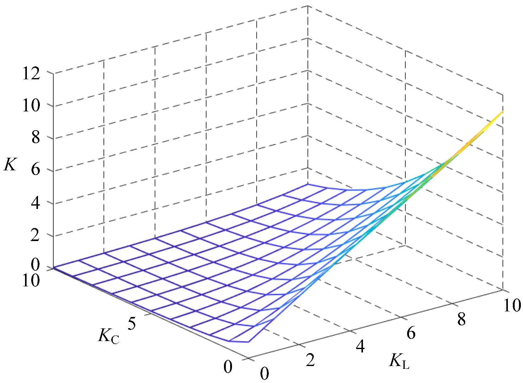
Figure 4 illustrates the change in K with KL and KC, and the conclusions can be drawn that, when KL is constant, K is inversely proportional to KC; on the other hand, when KC is constant, K is directly proportional to KL. According to this change rule, it is convenient to achieve the load impedance matching of the induction heating system by choosing the proper values of KL and KC.
Additionally, in the engineering application, the equivalent resistance (R) of the heating coil and workpiece combination is very small and has little influence on the resonant frequency and magnitude, which was demonstrated in the theory and simulation above. However, it will affect the load impedance angle. According to Equation (1), the load impedance angle at the resonant frequency ω3 is given as
φ Z 0 = a r c t g R ω 3 C 1 R ω 3 L 1
Generally, φZ0 is set to a negative value, because the capacitive load is convenient to fulfill the soft switching of the CSI-based H-bridge inverter.

2.3.3. Resonant Current

From Figure 2, the output resonant current (IH) of the LCLC load can be given as
I H = U H Z 0 = U H Q 2 R
Referring to Figure 2, the comprehensive parallel current of C1 and L1 is denoted as I1. Given a significantly large Q value (Q >1), the relationship between the resonant current Ir, IH, and I1 can be derived (Equation (12)).
I r U H Q R = Q I H = I 1
Obviously, there is IrI1, and the resonant magnitudes of them are closely related with the quality factor (Q).

2.3.4. Voltage Regulation Feature

In light of Figure 2, the voltage across the induction coil (L2) can be obtained as
U L 2 C 1 C 2 + 1 1 ω 3 2 L 1 C 2 × U H
Similarly, the voltage of the compensation capacitor C2 can be given as
U C 2 = 1 j ω C 2 × I r C 1 C 2 1 ω 3 2 L 1 C 2 × U H
It can be observed from Equations (13) and (14) that the resonant voltages across the induction coil L2 and its series compensation capacitor C2 decline in the LCLC load compared with the CLC load, due to adding inductor L1, which is beneficial for the induction coil.
Moreover, in light of Equations (13) and (14), there is
u L 2 + u C 2 = u C 1 = u H
Obviously, the induction coil voltage (uL2) can be easily regulated by adjusting the parameters of C1, C2, and L1, so as to set an appropriate induction heating power.

2.3.5. Influence of C2 and L1

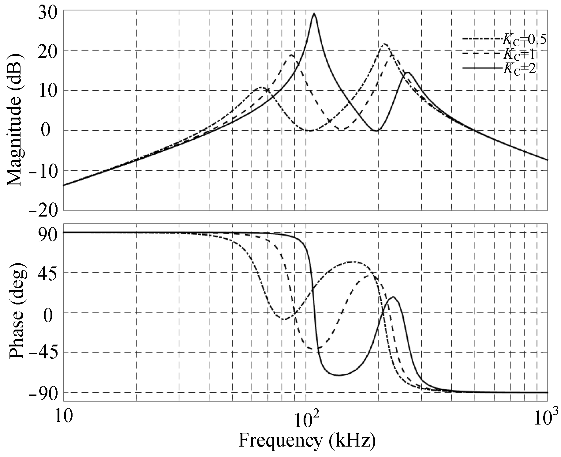
The influence of the compensation capacitor C2 and inductor L1 on the resonant characteristics of the LCLC circuit is simulation-analyzed in this section. The main simulation parameters are the same as those in Section 2.2. Figure 5 illustrates the bode diagram of the impedance transfer function of the LCLC load when C2 equals 193.3 nF, 386.6 nF, and 773.2 nF, respectively.
From Figure 5, it can be seen that the smaller C2 (the larger KC), the higher the parallel resonant frequency ω3 and the larger the resonant impedance angle, which will result in lowering the power factor and power transmission efficiency. At the same time, the resonant magnitude at ω3 is relatively larger than that under the other two values of C2, and the frequency band between ω2 and ω3 is narrow, which will have an adverse effect on the stability of the system. On the contrary, in the case of a large value of C2, the frequency band between the three resonant points is wide, and the capacitive impedance angle is also small, which is convenient for the system to work under a weak capacitive condition. As a result, C2 is appropriate for taking a relatively large value.
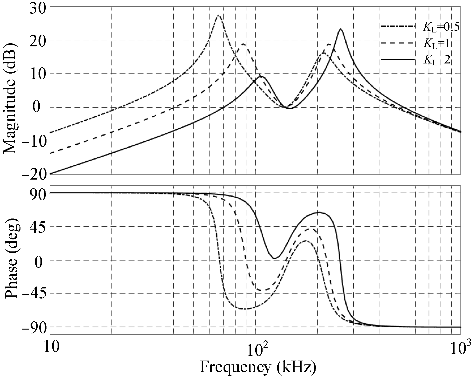
Figure 6 depicts the bode diagram of the impedance transfer function of the LCLC load when L1 takes the value of 1.64 μH, 3.28 μH, and 6.56 μH, respectively, and the other parameters remain unchanged. It can be seen from Figure 6 that the smaller the value of L1 (the larger KL), the higher the resonant frequency of ω3 and the higher the resonant magnitude, and vice versa. Therefore, it is necessary to take an appropriate value of L1 from the overall perspective of impedance matching and power adjustment.

3. Results and Discussion

3.1. Comparative Analysis of LC, CLC, and LCLC Resonant Characteristics

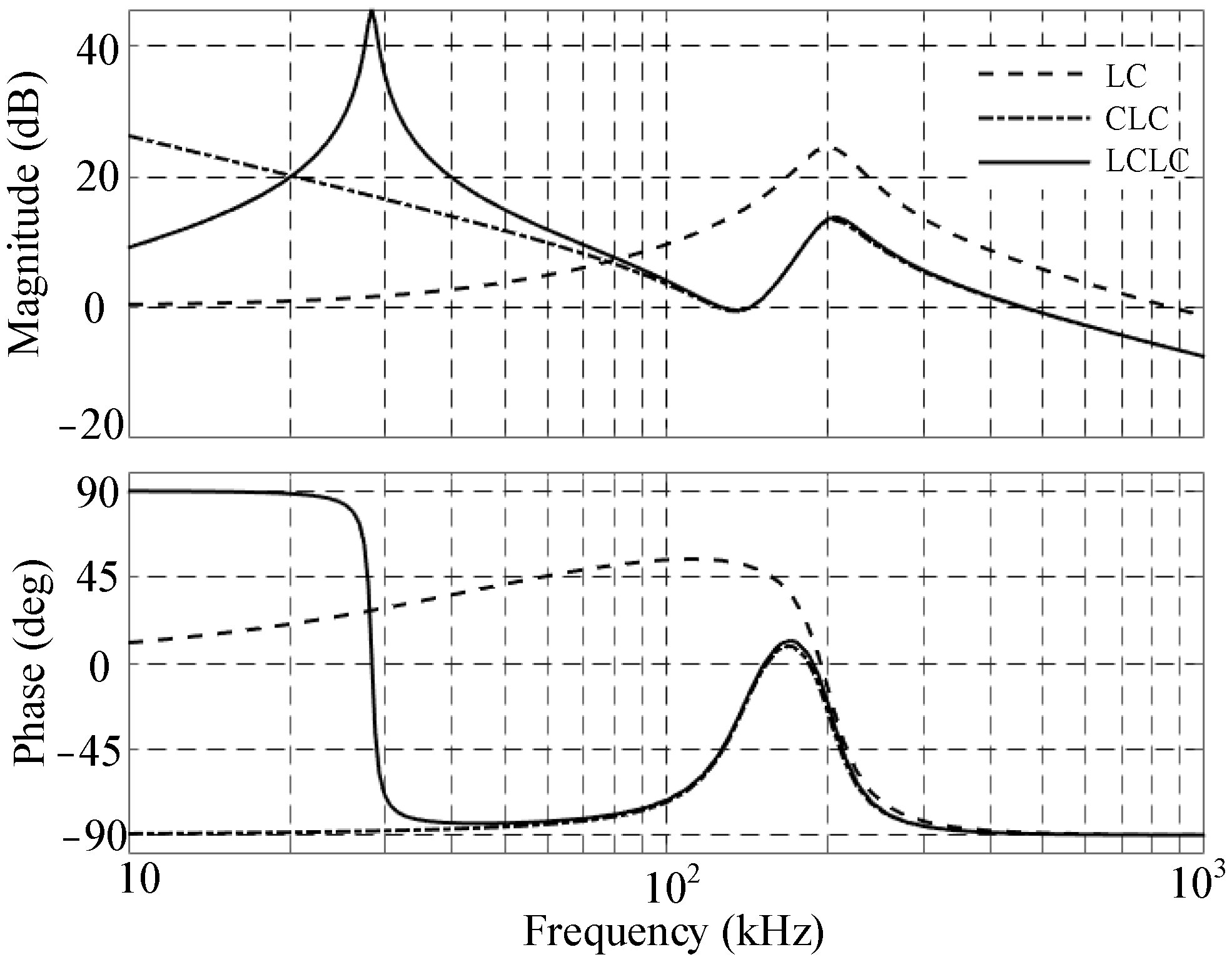
Figure 7 shows the bode diagrams of the impedance transfer functions of the LC, CLC, and LCLC load. Referring to Section 2, the simulation parameters of the three loads are the same, and moreover, for the purpose of comparative analysis, L1 is set as 40 μH, and the parallel capacitor C of the LC load is set as 1/C = 1/C1 + 1/C2.
According to Figure 7, the analysis conclusions can be drawn as follows.
(i) The highest resonant frequencies (ω3) of the three loads are basically the same due to the parameter matching of the capacitors (1/C = 1/C1 + 1/C2). In particular, since the value of L1 is relatively large, the resonant characteristics of the CLC and LCLC load centered on ω3 are similar, which is consistent with the analysis conclusion of Equation (8).
(ii) At the highest resonant point (ω3), compared with the LC load, the resonant magnitudes of the CLC and LCLC load are much smaller, which is beneficial to the impedance matching of the induction heating system.
(iii) In the frequency band ω > ω3, the resonant characteristics of the three loads tend to be consistent. That is because when the frequency is high, the capacitive reactance is close to the short circuit, and the inductive reactance is close to the open circuit, so both the CLC and the LCLC circuits tend towards the LC circuit.
(iv) In the low-frequency band, the impedance of the LC circuit is much smaller and changes to a resistive load gradually with the decrease in ω. As for the LCLC circuit, the impedance approximates parallel inductive reactance ωL1 when ω < ω2. Contrarily, for the CLC circuit, the equivalent impedance takes on a capacitance feature, and the large impedance will cause an excessive output voltage of the CSI-based induction heating power supply in the start-up phase.

3.2. Characteristic Analysis of Induction Heating System Based on LCLC Load

3.2.1. Frequency Tracking Control

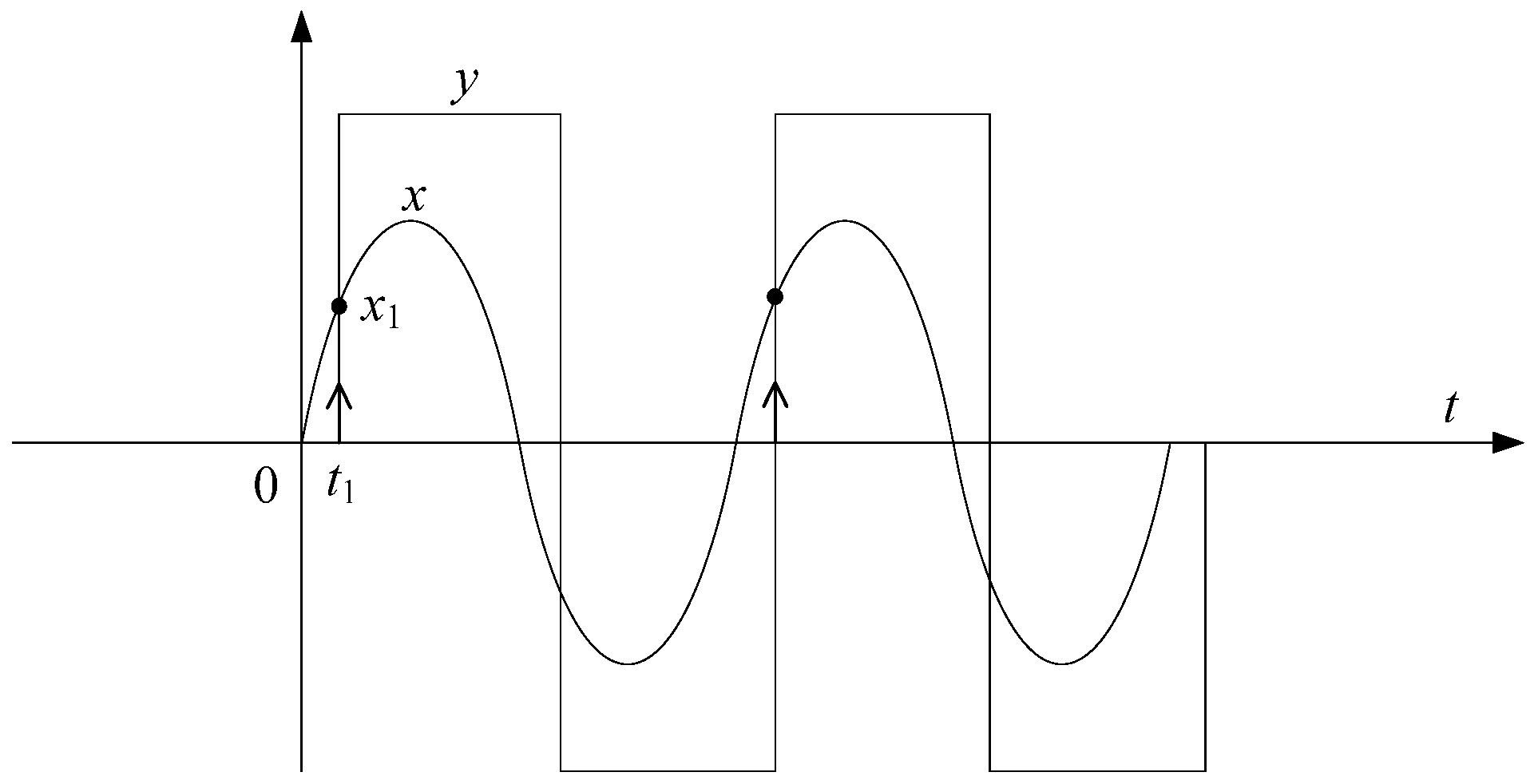
The tracking of frequency holds significant importance in the context of induction heating power supply. In this paper, a straightforward method for frequency control was proposed, as illustrated in Figure 8. Where the sine wave x is the output voltage of the power supply, the square wave y is the output current of the power supply. The x signal is sampled once within a y period, and the resulting sampling value x1 serves as the control variable for frequency tracking. Manipulating the sampling value x1 to zero or a specific setpoint Δx enables precise resonance frequency tracking of the power output load. The specific steps are as follows:
(i) Set the initial frequency of induction heating power supply as f = f0;
(ii) Set parameter Δx < 0;
(iii) Obtain the sampling value x1 and the sampling deviation Δx1 = x1 − Δx;
(iv) The Δx1 is fed into the proportional integration (PI) regulator, which outputs a frequency compensation signal Δf;
(v) Update frequency value f = f + Δf;
(vi) Enter the next y control period and return to step 2.

3.2.2. Comparison and Analysis

In terms of Figure 1, a simulation mode of the high-frequency induction heating system is built based on MATALB. The circuit parameters are set as follows: grid voltage us = 380 V, rated power P = 30 kW, Ld = 5 mH, C1 = C2 = 586 nF, L1 = 4.3 μH, L2 = 2.17 μH, and R = 0.68 Ω. In light of (2), the resonant frequencies (fr) in theory of the CLC and LCLC circuits are 200 kHz and 213.3 kHz, respectively. In addition, the initial working frequency of the system is set as 220 kHz and the frequency control parameter Δx = −0.5.
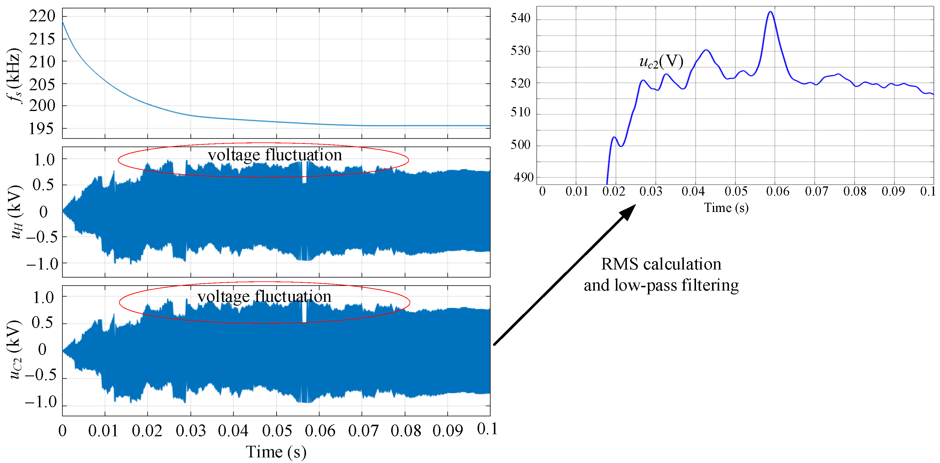
Firstly, the branch of the parallel inductor L1 is disconnected to obtain the CLC resonant load. Figure 9 depicts the simulation waveforms of the CLC-based high-frequency induction heating power supply at the startup, and they are the working frequency fs, the output voltage uH, and the capacitor voltage uC2 from up to bottom. It can be seen from Figure 9 that, through the frequency tracking control, fs reaches the stable value of 195.56 kHz near t = 0.07 s, and meanwhile, fs locks the resonant frequency fr (200 kHz) of the CLC circuit basically. A little error (4.44 kHz) of fs deviating from fr is to guarantee the weak capacitive feature of the system, so as to accomplish soft switching.
Observing the voltage waveforms, there are fluctuations in both uH and uC2 before fs is stable, and the maximum fluctuation is near 1 kV. Moreover, the fluctuation rule of the two voltages is similar, but they have an inverse phase angle. The ultimate reason for the fluctuation is that the continuous changing of fs results in the low-frequency disturbance of the output current (iH) and correspondingly causes the voltage fluctuation.
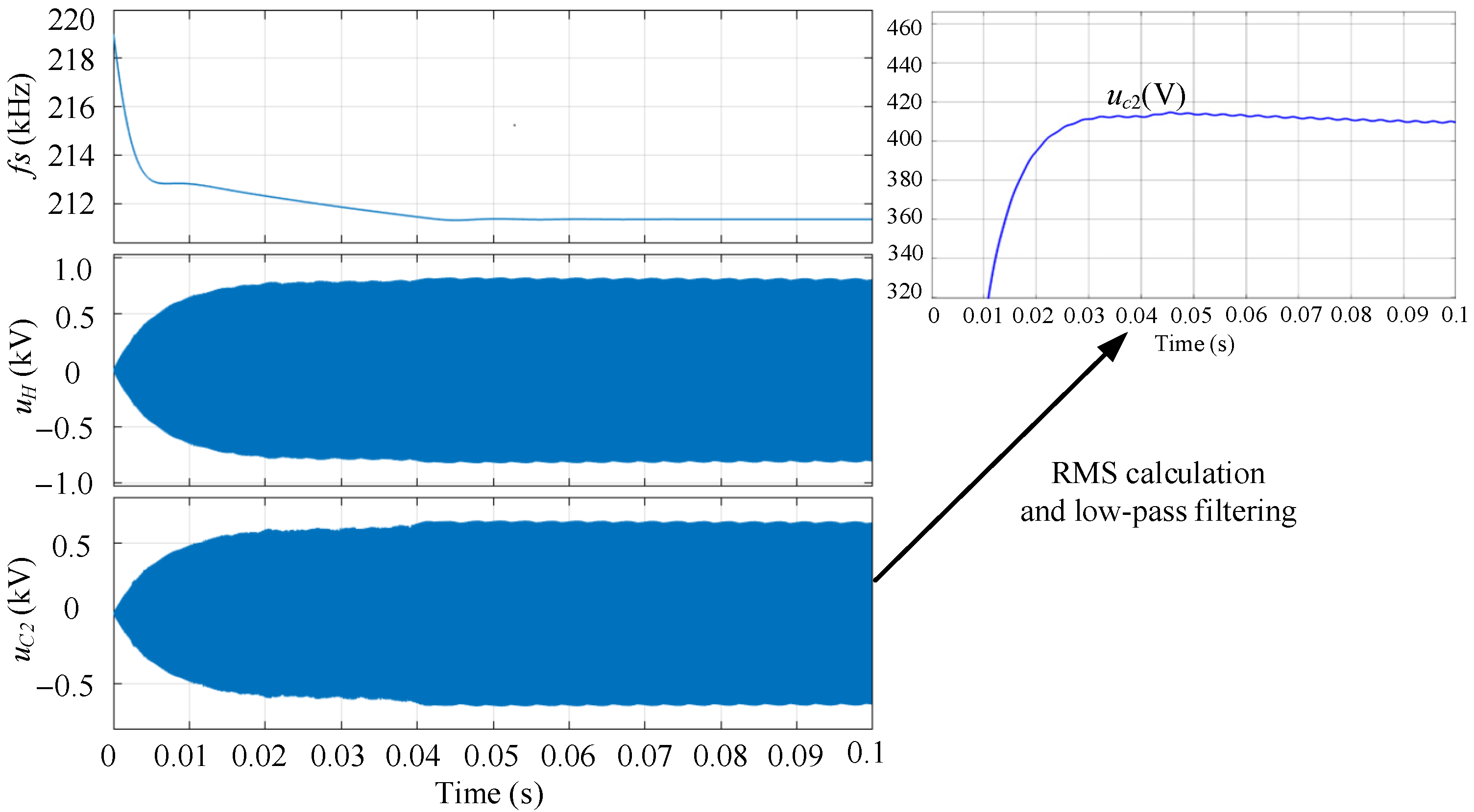
Figure 10 shows the simulation waveforms of the LCLC-based high-frequency induction heating system at the startup. At t = 0.05 s nearby, fs reaches a stable value of 211.34 kHz, which is also controlled to be smaller than the resonant frequency fr (213.3 kHz) of the LCLC load. Obviously, both uH and uC2 remain stable and without obvious fluctuation during the continuous variation in the working frequency (fs). In fact, the low-frequency disturbance current component is by-passed through the added parallel inductor L1, because of which it has a relatively low impedance in the low-frequency band, so as to suppress the voltage fluctuation. In addition, the voltage ripple is caused by the thyristor-based rectifier.
According to the aforementioned simulation analysis, in comparison with the CLC resonant load, the LCLC resonant load effectively mitigates output voltage fluctuations resulting from variations in the operating frequency of high-frequency induction heating power supply, as evidenced by the localized amplification of RMS voltage depicted in Figure 8 and Figure 9. Meanwhile, LCLC resonance reduces device capacity requirements, thereby facilitating the selection and protection of inverter power devices.
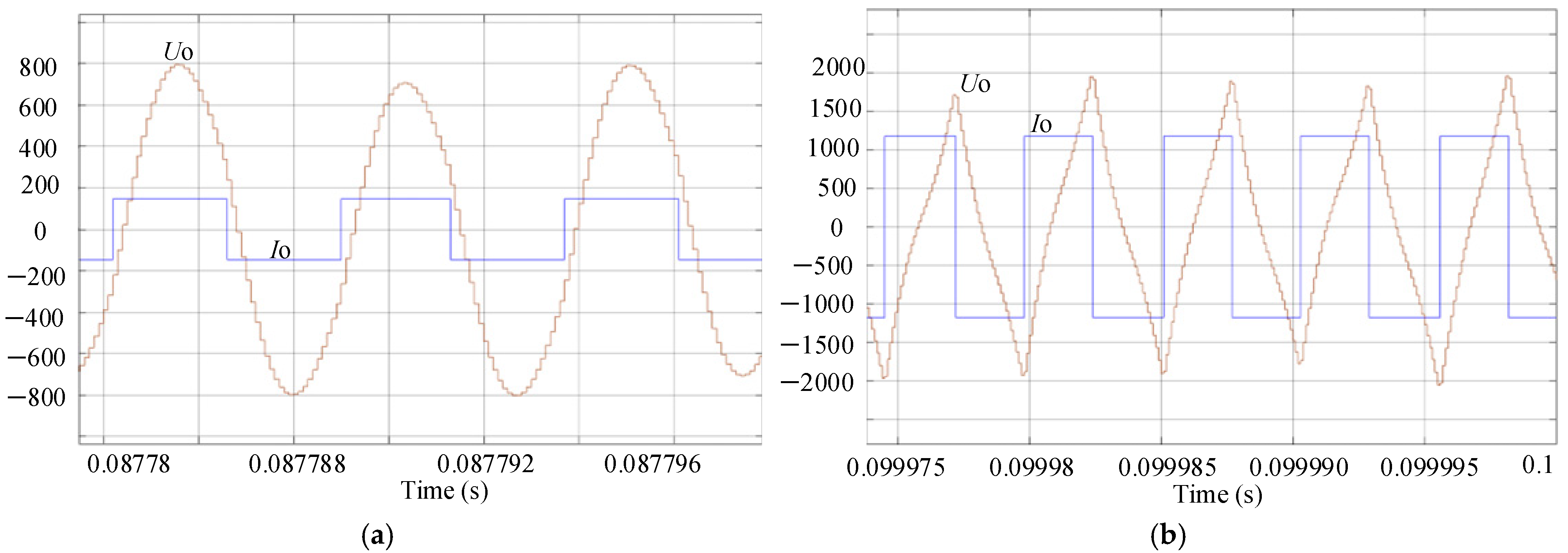
According to the theoretical analysis presented in Section 2.3.5, the KC value has an impact on the efficiency of the power supply. In order to validate this theoretical analysis, a comparative test was conducted. In Figure 11a, C1 = C2 = 586 nF, and L1 = 4.3 μH. On the other hand, in Figure 11b, C1 remained at 586 nF but C2 was reduced to 193.3 nF with L1 remaining constant at 4.3μH. Keeping all other parameters unchanged, we observed that reducing the C2 led to a significant decrease in power factor and subsequently lower power efficiency as depicted in Figure 11. Consequently, it is imperative for C2 to possess a larger value which aligns perfectly with our earlier theoretical analysis. In addition, Figure 12 illustrates the resonant frequencies corresponding to different values of L1. For Figure 11a, C1 = C2 = 586 nF and L1 = 4.3 μH, and for Figure 11b, C1 = C2 = 586 nF and L1 = 1.3 μH. The resonant frequency increases and the resonant impedance becomes larger as the value of L1 decreases, which also aligns with the outcomes of theoretical analysis.
To sum up, the output resonant impedance value Z0 can be adjusted to achieve impedance matching by appropriately selecting values for KL and KC. Moreover, when KL = KC = 0, the LCLC circuit is equivalent to the LC-type parallel resonant load. When KL = 0, that is, L1 is open, and the circuit is equivalent to the CLC-type load. Compared with the CLC-type load, the LCLC-type load has one more degree of freedom, and the load impedance matching is more flexible.

4. Conclusions

From the theoretical and simulation analysis of the proposed LCLC resonant circuit, the conclusions can be drawn as follows.
Firstly, there are three resonant points (ω2 < ω1 < ω3) of the LCLC circuit, and the highest one (ω3) is utilized for the induction heating application here, mainly considering the reliable and efficient operation of the heating equipment.
Secondly, in the high-frequency band (>ω3), the resonant characteristics of the LC, CLC and LCLC load tend to be consistent. On the contrary, in the low-frequency band (<ω1), the LCLC circuit has a smaller impedance than that of the CLC circuit, which can avoid the overvoltage across the output terminal of the current-source inverter in the start-up phase.
Thirdly, owing to the addition of one degree of freedom (L1), the LCLC resonant load has a more flexible impedance-matching capability than that of the CLC resonant load.
Finally, the CSI-based induction heating power supply has a better stability of its output voltage when connected with the LCLC resonant load than the other two conventional resonant loads (LC and CLC circuit).

Author Contributions

Conceptualization, S.X.; data curation, S.X.; formal analysis, Z.X.; funding acquisition, S.X. and H.X.; investigation, H.X.; methodology, S.X. and Z.X.; project administration, Z.X.; resources, Z.X.; software, S.X.; supervision, S.X.; validation, S.X., Z.X. and H.X.; visualization, S.X.; writing—original draft, S.X. and Z.X.; writing—review and editing, S.X., Z.X. and H.X. All authors have read and agreed to the published version of the manuscript.

Funding

This research was funded by Natural Science Foundation of Colleges and Universities of Jiangsu Province, grant number 23KJA120003.

Data Availability Statement

Data are contained within the article.

Acknowledgments

We highly appreciate the reviewers’ and editors’ useful suggestions for this work.

Conflicts of Interest

The authors declare no conflicts of interest.

References

  1. Lampa, M.; Mokrošová, L. Optimisation of the Thermal Process in Ladle Metallurgy in Terms of the Impact on Energy Consumption and the Environmental Burden During Steel Production. Rocz. Ochr. Sr. 2022, 24, 246–259. [Google Scholar] [CrossRef]
  2. Polushin, A.A.; Kamantsev, S.V.; Gryzunov, V.I.; Minakov, M.Y. Heat Treatment of Steel Rolls for Cold Rolling. Met. Sci. Heat Treat. 2011, 53, 225–229. [Google Scholar] [CrossRef]
  3. Gołaszewski, A.; Szawłowski, J.; Świątnicki, W.A. Multiphase Steel Microstructure and Properties Optimisation through a New Heat Treatment Process. Mater. Sci. Technol. 2021, 37, 1083–1089. [Google Scholar] [CrossRef]
  4. Asano, Y.; Nishi, T.; Yanagimoto, J. Continuous Heating System Using Electric Resistance Heating for the Hot Rolling of Stainless Steels. ISIJ Int. 2002, 42, 1112–1118. [Google Scholar] [CrossRef]
  5. Käsemann, C.-P.; van Lieshout, L.; Huart, M.; Sihler, C. Thyristor Crowbar System for the High Current Power Supplies of ASDEX Upgrade. Fusion Eng. Des. 2005, 75–79, 149–153. [Google Scholar] [CrossRef]
  6. Jia, G.; Li, M.; Shi, B.; Yu, X.; Liu, X. A Variable Frequency Injection Method for Modular Multilevel Converters in Variable Speed Drives. Energy Rep. 2023, 9, 939–947. [Google Scholar] [CrossRef]
  7. He, M.; Wang, Q.; Liu, X.; Shi, C.; Liu, T.; He, J. Analysis of Power Supply Heating Effect during High Temperature Experiments Based on the Electromagnetic Steel Teeming Technology. High Temp. Mater. Process. 2017, 36, 441–445. [Google Scholar] [CrossRef]
  8. Huang, C.-Y.; Lin, Y.-C.; Chen, H.-M.; Chen, Y.-C. Rapid Welding of Stainless Steel Wires Using Ultra-High Frequency Induction Heating. J. Chin. Inst. Eng. 2013, 36, 806–809. [Google Scholar] [CrossRef]
  9. Yilmaz, I.; Durna, E.; Ermis, M. Design and Implementation of a Hybrid System for the Mitigation of PQ Problems of Medium-Frequency Induction Steel-Melting Furnaces. IEEE Trans. Ind. Appl. 2016, 52, 2700–2713. [Google Scholar] [CrossRef]
  10. Ermolenko, D.; Iuferev, L.; Roshchin, O. The Resonant Induction Heating Method. Transp. Res. Procedia 2021, 54, 236–242. [Google Scholar] [CrossRef]
  11. Shami, U.T.; Shami, T.A. An Adaptive Load-matching Method for the Induction Heating Coil with DC Power Supply. Int. J. Circuit Theory Appl. 2024, 52, 5025–5041. [Google Scholar] [CrossRef]
  12. Aunsborg, T.S.; Duun, S.B.; Munk-Nielsen, S.; Uhrenfeldt, C. Development of a Current Source Resonant Inverter for High Current MHz Induction Heating. IET Power Electron. 2022, 15, 1–10. [Google Scholar] [CrossRef]
  13. Khati, A.; Kansab, A.; Taleb, R.; Khouidmi, H. Current Predictive Controller for High Frequency Resonant Inverter in Induction Heating. Int. J. Electr. Comput. Eng. 2020, 10, 255. [Google Scholar] [CrossRef]
  14. Namadmalan, A.; Moghani, J.; Abdi, B. Improved Modification of the Current Source Parallel Resonant Push-Pull Inverter for Induction Heating Applications. Int. Rev. Electr. Eng. 2010, 5, 390–396. [Google Scholar]
  15. Wang, H.; Chen, Y.; Liu, Y.-F. A Passive-Impedance-Matching Technology to Achieve Automatic Current Sharing for a Multiphase Resonant Converter. IEEE Trans. Power Electron. 2017, 32, 9191–9209. [Google Scholar] [CrossRef]
  16. Yang, X.; Zhang, Z.; Xu, M.; Li, S.; Zhang, Y.; Zhu, X.-F.; Ouyang, X.; Alù, A. Digital Non-Foster-Inspired Electronics for Broadband Impedance Matching. Nat. Commun. 2024, 15, 4346. [Google Scholar] [CrossRef]
  17. Tian, W.; Wang, L.; Yu, J.; Lv, Y.; Zhang, S.; Xu, Q.; Gao, B. A Hybrid Impedance Matching Network for Underwater Acoustic Transducers. IEEE Trans. Power Electron. 2023, 38, 7622–7633. [Google Scholar] [CrossRef]
  18. Chudjuarjeen, S.; Sangswang, A.; Koompai, C. An Improved LLC Resonant Inverter for Induction-Heating Applications with Asymmetrical Control. IEEE Trans. Ind. Electron. 2011, 58, 2915–2925. [Google Scholar] [CrossRef]
  19. Karuppusamy, S.; Sunandhitha, V.; Suraj, R.; Roja, T.S.; Sundararaman, K. Design and Implementation of High Frequency Induction Heating with LLC Resonant Load Matching Using ELTA. Int. J. Power Electron. Drive Syst. 2020, 11, 178. [Google Scholar] [CrossRef]
  20. Lucia, O.; Maussion, P.; Dede, E.J.; Burdio, J.M. Induction Heating Technology and Its Applications: Past Developments, Current Technology, and Future Challenges. IEEE Trans. Ind. Electron. 2014, 61, 2509–2520. [Google Scholar] [CrossRef]
  21. Park, S.M.; Jang, E.; Park, J.S.; Kim, J.-H.; Choi, J.-H.; Lee, B.K. Optimal Design of High-Frequency Induction Heating Apparatus for Wafer Cleaning Equipment Using Superheated Steam. Energies 2020, 13, 6196. [Google Scholar] [CrossRef]
  22. Espi-Huerta, J.M.; Dede Garcia Santamaria, E.J.; Garcia Gil, R.; Castello-Moreno, J. Design of the L-LC Resonant Inverter for Induction Heating Based on Its Equivalent SRI. IEEE Trans. Ind. Electron. 2007, 54, 3178–3187. [Google Scholar] [CrossRef]
  23. Roy, M.; Sengupta, M. A Commutation Strategy for IGBT-Based CSI-Fed Parallel Resonant Circuit for Induction Heating Application. Sādhanā 2017, 42, 153–161. [Google Scholar] [CrossRef]
  24. Szychta, E. The Results of the Rail Induction Heating by the Current Inverter with the Parallel Resonant Circuit. Prz. Elektrotech. 2016, 1, 205–209. [Google Scholar] [CrossRef]
  25. Zgraja, J. Dual-Frequency Induction Heating Generator with Adjustable Impedance Matching. IEEE Trans. Ind. Electron. 2019, 66, 8308–8317. [Google Scholar] [CrossRef]
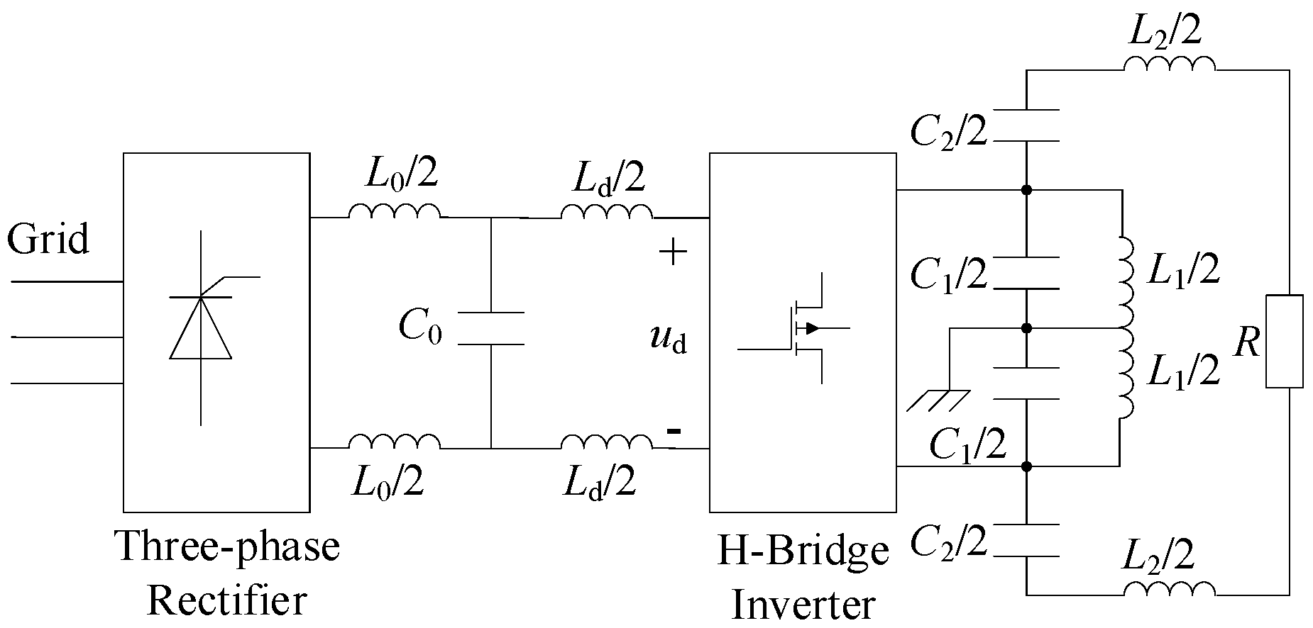
Figure 1. Main circuit structure of the high-frequency induction heating system based on the LCLC-based resonant circuit.
Energies 17 05892 g001
Figure 2. Equivalent circuit of the LCLC resonant load.
Energies 17 05892 g002
Figure 3. Bode diagram of the impedance transfer function of the LCLC load.
Energies 17 05892 g003
Figure 4. Influence of KL and KC on the impedance coefficient K.
Energies 17 05892 g004
Figure 5. Bode diagram of the impedance transfer function of the LCLC load under different parameters of C2.
Energies 17 05892 g005
Figure 6. Bode diagram of the impedance transfer function of the LCLC load under different parameters of L1.
Energies 17 05892 g006
Figure 7. Bode diagram of the impedance transfer functions of the LC, CLC, and LCLC load.
Energies 17 05892 g007
Figure 8. Frequency tracking control schematic.
Energies 17 05892 g008
Figure 9. Simulation waveforms of the high-frequency induction heating power supply based on CLC load.
Energies 17 05892 g009
Figure 10. Simulation waveforms of the high-frequency induction heating power supply based on the LCLC load.
Energies 17 05892 g010
Figure 11. The effect of KC on power efficiency. (a) Power supply output voltage and current waveform (C2 = 586 nF). (b) Power supply output voltage and current waveform (C2 = 193 nF).
Energies 17 05892 g011
Figure 12. The effect of L1 on the resonant frequency.
Energies 17 05892 g012
Disclaimer/Publisher’s Note: The statements, opinions and data contained in all publications are solely those of the individual author(s) and contributor(s) and not of MDPI and/or the editor(s). MDPI and/or the editor(s) disclaim responsibility for any injury to people or property resulting from any ideas, methods, instructions or products referred to in the content.