1. Introduction
Typically, power network metering systems are oriented for 50 Hz or 60 Hz main component of current and voltage. However, electrical power metering and its quality evaluation for a distorted current and voltage require the utilization of power analyzers that are compliant with the standard IEC 61000-4-7 [
1]. Such devices are used in a wide range of applications such as the designing and testing of power supplies, analyzing the performance of motors and generators, and evaluating the efficiency of renewable energy systems and current/voltage transformers, voltage dividers, or transducers [
2,
3,
4,
5]. In cases when an extension of the current range is required, the Rogowski coil with or without its signal conditioner may be used. The impact of the current transducer on the accuracy is essential in order to ensure the required measuring accuracy of the complete system, but multiple factors influencing its conversion performance should be analyzed [
6,
7,
8,
9,
10,
11,
12]. The Rogowski coil without the signal conditioner or any active electronic component should be compliant with the standards IEC 61869-1 and IEC 61869-10 as in the case of the low-power passive-current transformer [
13,
14]. The term low power defines that such devices have no defined rated output power, and they are expected to operate in the non-load/idle or short-circuit state depending on their output type—voltage or current—respectively. The Rogowski coil with the signal conditioner or any other active component should be compliant with the standards IEC 61869-1 and IEC 60044-8 as in the case of the electronic current transformer (ECT) [
13,
15]. It is worth mentioning that the IEC TC 38 WG 37 is currently working on the new standard, the IEC 61869-7/8. The output voltage of the Rogowski coil is shifted in phase by 90°, and the RMS value of each harmonic is multiplied by its order. Therefore, the electrical integrator circuit is used to convert this voltage into a signal that is, in theory, directly proportional to the RMS value of the primary current harmonics and that introduces no additional phase displacement. The advantage of the Rogowski coil is its linear behavior with the current RMS value and frequency as there is no magnetic core. The limitations of the existing systems for current transducer accuracy evaluation in general concern the fact that they may be used to compare the output current or voltage of tested transducers with the reference source. Moreover, in the case of the mainly used devices, their application is only for the sinusoidal current of frequency, 50 Hz or 60 Hz (the current comparator for testing the transformation accuracy of current transformers). The idea of the measurement setup for an accuracy measurement of the low-power current transformer with a current comparator is presented in the standard IEC 61869-1. To determine the accuracy of higher harmonic transformation, a digital acquisition board or digital power meter may be used. However, the supply system that is able to ensure the high current RMS value and reference source is still required [
16,
17,
18,
19,
20,
21].
The original contribution of this research concerns a comparison of the results of a conversion accuracy evaluation of the combined transducer with the Rogowski coil for distorted current harmonics, such as those for the complete systems provided by two manufacturers, as well as for the separate Rogowski coils. The tests are made for distorted current harmonics with adjustable RMS values and phase angles in relation to the main component. Compliance with the standard IEC 61000-4-7 of the precision power meter/analyzer is evaluated with the used measuring current range extensions provided by the Rogowski coils with and without their default signal conditioners. Therefore, the values of the percentage measured value error and the percentage nominal value error for a given harmonic resulting from their usage are determined for frequency from 50 Hz to 2500 Hz (50th-order higher harmonic). The conversion accuracy of the Rogowski coils is evaluated in accordance with the limits defined in the standard IEC 61869-10, while the reference for the assessment of the conversion accuracy of the complete systems with active components is the standard IEC 60044-8. In both cases, the requirements of the generic standard IEC 61869-1 are of the utmost importance. It has been demonstrated that the application of tested current transducers has a significant impact on the overall accuracy of the measuring system (composed of the precision power meter/analyzer) used for the electrical power metering, especially for the non-sinusoidal conditions, as well as for current harmonic evaluation. The greatest impact has the insufficiently poor, in relation to the Rogowski coil, conversion accuracy of the signal conditioner/integrator. However, it should be noted that their performance is different regarding the particular product. Therefore, the proposed method for the wideband characterization of the influence of the whole conversion system on the measuring accuracy of the power meter/analyzer is essential for a conscious choice of the proper current transducer for the electrical substation metering equipment.
The novelty of this paper concerns the presentation of the simplified evaluation procedure for the characterization of the influence of current transducers on the distorted current measuring accuracy of digital power meters. The proposed evaluation method ensures similar conditions as are present for the high RMS value of the distorted current in order to ensure the required test scenario for the equipment designed for power network metering purposes. It should be noted that the effect of the return conductor in the applied ampere-turns method is insignificant for a comparation of the results for Rogowski coils and combined transducers as the tests are performed in the same conditions. Moreover, the percentage of measured value errors determined only for the first RC in accordance with the datasheet provided by its manufacturer should be within ±0.5% for the 50 Hz component of the primary current just like it was determined with the aid of the proposed solution.
The organization of the paper is as follows: After the introduction, we present the requirements for the evaluation of the conversion accuracy of passive and active current transducers and definitions of evaluated quantities. In the third paragraph, the objects of the research, methodology, and the measuring setup are discussed. In the last part before the conclusion, we present the results of the tests for the Rogowski coils and combined transducers.
2. The Requirements for Evaluation of the Conversion Accuracy of Passive and Active Current Transducers and Definitions of Evaluated Quantities
The electromagnetic compatibility (EMC) standard IEC 61000-4-7 defines the requirements for the measuring apparatus being used for the evaluation of the spectral components of current, voltage, and active power in the frequency range up to 9 kHz [
1]. The accuracy requirements for the power analyzers are reported in
Table 1.
A class I measuring apparatus is recommended by the standard IEC 61000-4-7 for precise measurements, e.g., an EMC emission evaluation of devices. Class II instruments may be used for general surveys or EMC measurements when increased measurement uncertainty is acceptable.
Two measurement errors are calculated in order to determine the impact of the Rogowski coil with signal conditioner on the fulfillment of the requirements presented in
Table 1 by the power analyzer: the percentage of measured value error and the percentage of nominal value error.
The percentage of measured value error (ratio error in the standard IEC 61869-1) of the distorted current for the h order harmonic is defined by the following equation for the Rogowski coil and the signal conditioner with the voltage output:
where
kCS—the conversion ratio of the first signal conditioner (for a 400 A RMS measured current, it is equal to 1777.77 A/V, resulting from the selected input current range 400 A in relation to the maximum output voltage RMS value equal to 0.225 V; for 200 A, it is 888.88 A/V; for 50 A, it is equal to 444.44 A/V, resulting from the selected input current range 100 A in relation to the maximum output voltage RMS value equal to 0.225 V),
UhSC—the RMS value of the voltage higher harmonic measured by the digital power analyzer through a Rogowski coil and a signal conditioner, and
IhRC—the RMS value of the h order current higher harmonic inside a Rogowski coil.
The percentage of measured value error (ratio error in IEC 61869-1) of the distorted current for the h order harmonic is defined by the following equation for the Rogowski coil:
where
lRC—the conversion ratio of the Rogowski coil (for the first RC, it is equal to 22.5 mV/1 kA; for the second type, it is equal to 100 mV/1 kA),
UhRC—the RMS value of the voltage higher harmonic measured by the digital power analyzer with a Rogowski coil, and
Oh—the h order of the distorted current/voltage harmonic.
The percentage of measured value error (current error in the standard IEC 61869) of the distorted current for the h order harmonic is defined by the following equation for a Rogowski coil and a signal conditioner with the current output:
where
nSC—the conversion ratio of the second signal conditioner (for a 400 A RMS measured current, it is equal to 400 A/A, resulting from the selected input current range 400 A in relation to the maximum output current RMS value equal to 1 A; for a 200 A RMS measured current, it is equal to 250 A/A, resulting from the selected input current range 250 A in relation to the maximum output current RMS value equal to 1 A; for a 50 A RMS measured current, it is equal to 100 A/A, resulting from the selected input current range 100 A in relation to the maximum output current RMS value equal to 1 A), and
IhSC—the RMS value of the current higher harmonic measured by the digital power analyzer with a Rogowski coil and a signal conditioner with the current output.
The percentage of nominal value error of the distorted current for the h order harmonic is calculated from the following equation for the Rogowski coil and the signal conditioner with the voltage output:
where
Unom is equal to 0.75 V, resulting from the used voltage range of the measurement instrument (DPM voltage input).
The percentage of nominal value error of the distorted current for the
h order harmonic is calculated from the following equation for the RC and the signal conditioner with the current output:
where
Inom is equal to 1 A, resulting from the used current range of the measurement instrument (digital power meter current input) for the RMS value of the measured current being the equivalent of 400 A and 200 A or 0.5 A for the RMS value of the measured current being the equivalent of 50 A.
The percentage of nominal value error of the distorted current for the
h order harmonic is calculated from the following equation for the Rogowski coil:
where
Unom is equal to 25 mV, resulting from the used voltage range of the measurement instrument (digital-power-meter current-sense voltage input).
The values of the phase shift (phase displacement in the standard IEC 61869) specified for the
h order harmonic of the distorted current resulting from the usage of the Rogowski coil with the signal conditioner may be determined from the following equation:
where
φhSCRC—the phase angle between the h order and the fundamental harmonics of the distorted secondary current/voltage measured by the digital power analyzer through a Rogowski coil with a signal conditioner, and
φhPA—the phase angle between the h order and the fundamental harmonics of the distorted current measured directly by the digital power analyzer.
The values of the phase shift (phase displacement in the standards IEC 61869) specified for the
h order harmonic of the distorted current resulting from the usage of the Rogowski coil may be determined from the following equation:
where
φhRC—the phase angle between the h order and the fundamental harmonics of the distorted output voltage from a Rogowski coil measured by the digital power analyzer.
The new edition of the standard IEC 61869-1, released in the year 2023, defines the optional wideband accuracy classes of the inductive current and voltage transformers [
13]. In the case of the current transducers, it concerns the conversion accuracy of distorted and sinusoidal currents of increased frequency. Five accuracy classes for harmonics and higher frequency sinusoidal signals are defined: WB0 from the 2nd to 13th harmonic, WB1 for a 3 kHz bandwidth, WB2 for a 20 kHz bandwidth, WB3 for a 150 kHz bandwidth, and WB4 for a 500 kHz bandwidth. Therefore, the combined accuracy class of the wideband current transducer may be defined as 0.1-WB1, taking into consideration its performance for the sinusoidal current of the main frequency equal to 50 Hz or 60 Hz (0.1 accuracy class) and for the wideband applications. The class WB1 ensures that, in correlation with the mentioned 0.1 accuracy class, the values of the current error and phase displacement do not exceed ±1%/° in a 1 kHz bandwidth, ±2%/° above 1 kHz up to 1.5 kHz, and ±5%/° above this frequency up to 3 kHz. If the accuracy class of the wideband current transducer is defined as 0.5-WB1, this means that for the sinusoidal current of the frequency 50 Hz/60 Hz, its accuracy class is 0.5; additionally, for the wideband applications, the values of the current error and phase displacement do not exceed ±5%/° in a 1 kHz bandwidth, ±10%/° above 1 kHz up to 1.5 kHz, and ±10%/±20° above this frequency up to 3 kHz. The standard IEC 61869-1 defines the test procedure to be performed for the distorted primary current with the main component of the rated frequency and a single higher harmonic [
13]. The Rogowski coil without a signal conditioner or any active electronic component is also covered by the standard IEC 61869-10 as the low-power passive-current transformer [
14]. The Rogowski coil is required to evaluate the influence on the variation of the current frequency in the range from 99% to 101% of the rated value. It is worth mentioning that, due to the fact that the output voltage of the Rogowski coil is proportional to the current multiplied by its frequency, the results may be corrected. Tests for accuracy in respect of the positioning of the primary conductor and for the impact of magnetic fields from other phases are also obligated. Moreover, the accuracy type test for the Rogowski coils should be expended with the evaluation of the influence of the ambient temperature and humidity [
21]. The requirements for the conversion accuracy of harmonics in the standard IEC 61869-10 are the same as in the standard IEC 61869-6 for the accuracy class extension for quality metering up to 3 kHz and for the WB1 wideband accuracy class in the standard IEC 61869-1 (the standard IEC 61869-6 is withdrawn and its requirements are included in this document) [
13,
22]. The Rogowski coil with the signal conditioner or active electronic components is covered by the standards IEC 61869-1 and IEC 60044-8 as in the case of the electronic current transformer (ECT) [
13,
15]. The standard IEC 60044-8 defines the accuracy requirements on harmonics separately for the power and the quality metering. In the first case for each accuracy class defined for the conversion of the 50 Hz/60 Hz sinusoidal primary current, the limiting values of the current error and the phase displacement of the harmonics up to, and including, the 13th order are provided. In the case of quality metering, the requirements are defined in accordance with the standard IEC 61000-4-7 that the current error and phase displacement should not exceed ±1%/° for 1st and 2nd-order harmonics and ±5%/° up to, and including, their 50th order [
1]. It is recommended to use, for the accuracy test of the ECT, a current that is supplied by a power amplifier and a coaxial shunt as a reference voltage source. The test procedure should be performed for the distorted primary current with the main component of the rated frequency and a single higher harmonic. However, if it is difficult to achieve, it is accepted that the accuracy test is made for the primary current containing the fundamental harmonic of the ECT-rated frequency and only one single higher harmonic of frequency from tested range for each measuring conditions.
3. The Objects of the Research, Methodology, and the Measuring Setup
Tested objects are two flexible clip-around Rogowski coils with the signal integrators designed for the electronic measurement of AC current with galvanic separation between the primary conductor and the secondary circuit. Their most common application is the power quality monitoring concerning the evaluation of the parameters such as harmonics, voltage sags, and swells, as well as transient disturbances. In the case of the first-tested combined transducer, its manufacturer declared that it is in the 0.5 accuracy class of the IEC 61869-2 even if this standard does not apply to Rogowski integrators [
23]. Its specified measurement bandwidth is from 10 Hz to 1500 Hz. In the case of the second conversion system, it results from the specification provided by its manufacturer that the measuring error does not exceed ±1%, while the maximum detectable harmonic frequency is 2 kHz.
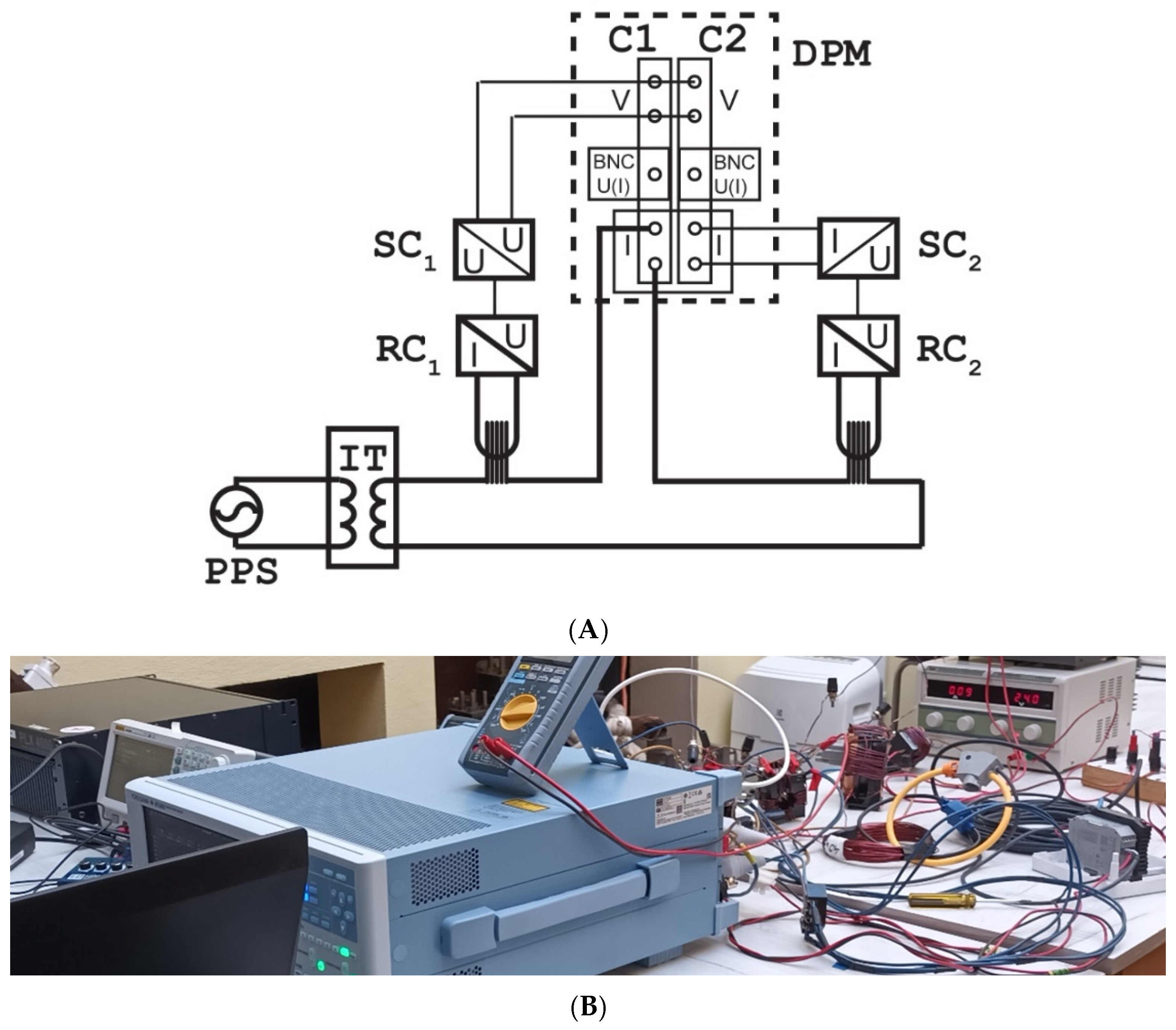
The connection diagram of the measuring setup used for the evaluation of the impact of the Rogowski coil with the signal conditioner on the distorted current metering accuracy of the digital power analyzer is presented in
Figure 1.
The following notations are used in the above figure:
DPM—digital power meter/analyzer WT5000 (Yokogawa, Tokyo, Japan) (V—voltage terminal, U(I)—current-sense terminal, and I—current terminal, C1/2 – channel 1/2) with the accuracy for harmonic current/voltage measurements ±(0.1% of reading + 0.1% of range between 1 kHz and 10 kHz), RC1—first Rogowski coil (RC), RC2—second RC, SC1—signal conditioner for the first RC, SC2—signal conditioner for the second RC, PPS—programmable power supply, and IT—insulation transformer.
The copper wire is formed into a 40-turn coil-shaped circular. The tested Rogowski coils surround all these wires that are placed perpendicularly in its center. The influence of the return conductor may be neglected since the change in the conversion accuracy between the RC and combined transducer (while the RC is operating in the exact same conditions) is essential in this presented study. The distorted current in the wire with programmable levels of main and single higher harmonics and a selectable phase angle of higher harmonics in relation to its main component is supplied by the PPS formed from the audio power amplifier and the two-channel arbitrary waveform generator (voltages from both channels are added on the signal transformer to obtain the distorted input voltage for the amplifier). The current input of the first DPM channel is used to measure the RMS values of these current harmonics and their phase angles. The voltage input is used to measure the output voltage from the first signal conditioner of the first Rogowski coil. This voltage is also measured by the voltage input of the second channel of the DPM, while the output current of the second signal conditioner for the second Rogowski coil is measured by its current input. Therefore, the phase angles of the harmonics in this current are able to be determined in relation to the supplying current from the PPS measured by the current input of the first DPM channel. The output voltage of the first signal conditioner and the output current of the second signal conditioner are proportional to the equivalent current resulting from 40 turns of the wire supplied by the PPS. Therefore, to determine the values of the defined percentage of measured/nominal value error, the current measured by the DPM must be multiplied by 40 in accordance with the following equation:
where
z—the number of turns of the coil forming the equivalent primary current of the Rogowski coil under test, and
IhPA—the RMS value of the current harmonic measured directly by the DPM.
In these test conditions, the evaluated percentage of the measured value error of a given harmonic of the distorted current is defined by Equation (1) for the signal conditioner with the voltage output, while the percentage of the nominal value error of a given harmonic is calculated by Equation (4). In the case of the signal conditioner with the current output, the percentage of the measured value error of a given harmonic of the distorted current is defined by Equation (3), while the percentage of the nominal value error of a given harmonic is calculated by Equation (5). The values of the phase shift resulting from the usage of the Rogowski coil with the signal conditioner (with both output types) are determined from Equation (8).
The waveforms used for tests contained a 50 Hz main component and its single higher harmonic: 3rd, 5th, 7th, 9th, 10th, 11th, 13th, 15th, 20th, 25th, 30th, 40th, and 50th (60th). Its percentage level was equal to 5% or 2% of the distorted current first harmonic, and the phase angle was set to 0° in relation to it. The RMS values of the 50 Hz main component in the distorted currents used for the test were equal to 1.25 A, 5 A, and 10 A. Therefore, the measured current by the Rogowski coils for the 40 wires in their center for these conditions was the equivalent of the RMS values equal to 50 A, 200 A, and 400 A.
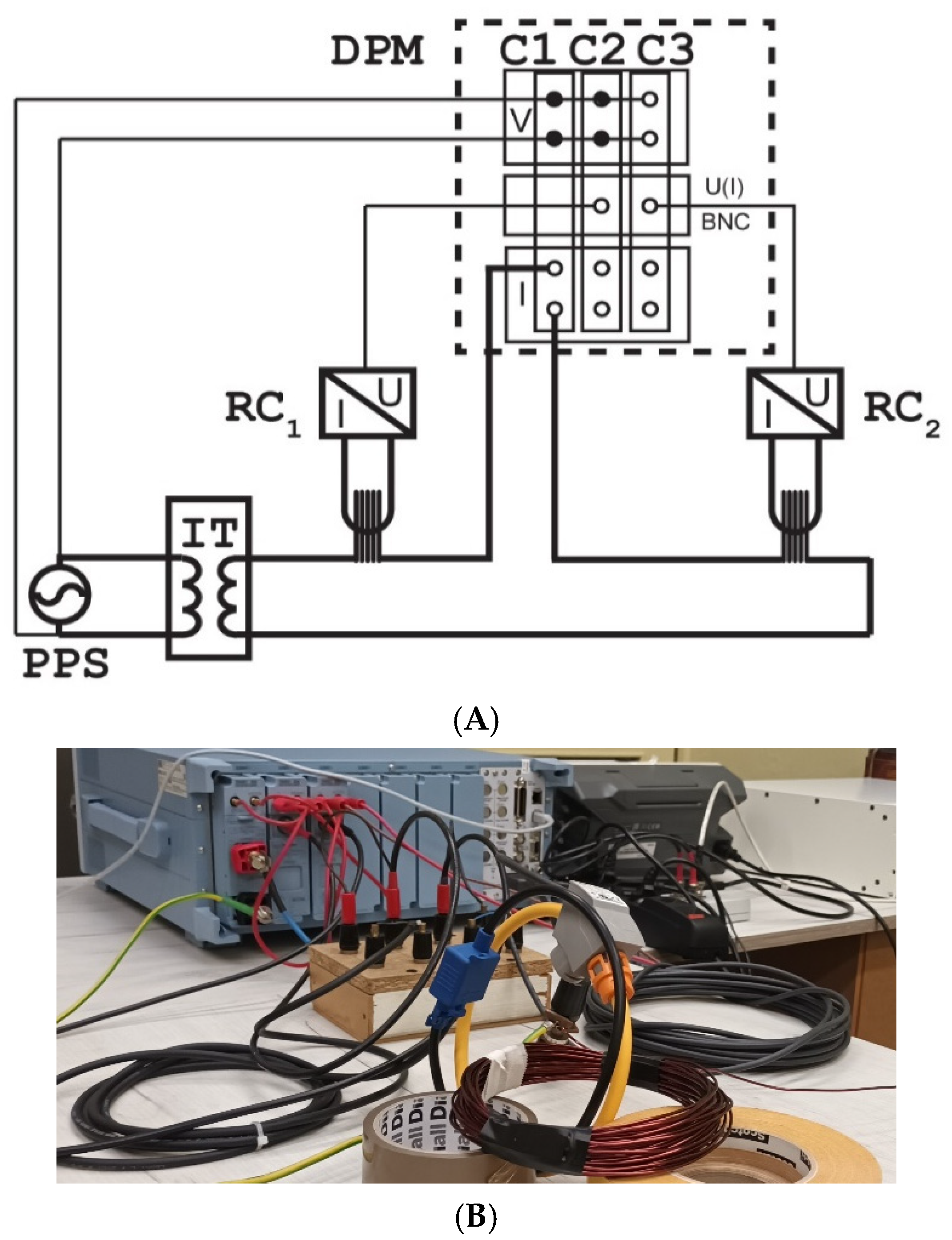
In the next stage of the laboratory studies, the impact of the separate Rogowski coil (without the signal conditioners) on the digital power analyzer’s current measurement accuracy was analyzed. The connection diagram of the measuring setup is presented in
Figure 2.
The current input of the first DPM channel is again used to measure the RMS values and the phase angles of the distorted current harmonics supplied by the PPS to the copper wire formed into a 40-turn coil-shaped circular. The tested Rogowski coils surround all these wires that are placed perpendicularly in its center. The voltage inputs of all three DPM channels are this time applied to measure the output voltage from the PPS. Therefore, the phase angles of the harmonics in the output voltages of tested Rogowski coils measured by the current-sense inputs of DPM channels 2 and 3 are able to be determined in relation to the supplying current from the PPS measured by the current input of the first DPM channel. The output voltage of the Rogowski coil is proportional to the derivative of the primary current. Therefore, it is shifted in phase by 90°, and the RMS value of each harmonic is multiplied by its order. In this case, the evaluated percentage of the measured value error of a given harmonic of the distorted current is defined by Equation (2), while the percentage of the nominal value error of a given harmonic is calculated by Equation (6). The values of the phase shift resulting from the usage of the Rogowski coil with the signal conditioner are determined by Equation (8).
4. Results of Tests of Rogowski Coils and Combined Transducers
This paragraph with the results is divided into two sections—the results of the tests for the Rogowski coils used without their signal conditioner (a) and the combined transducers composed of the Rogowski coil and its signal conditioner (b).
- (a)
The results for the separate Rogowski coils (RCs) without their signal conditioner.
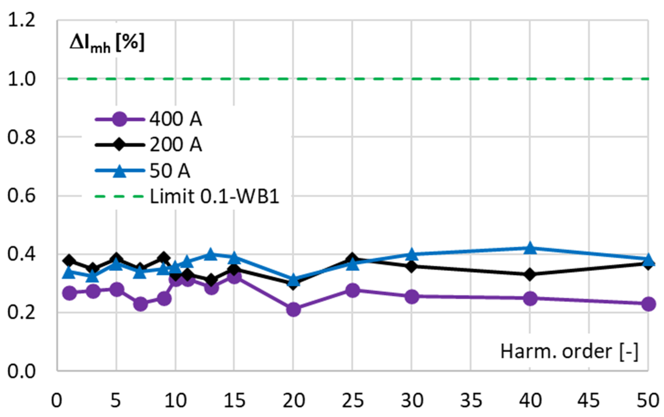
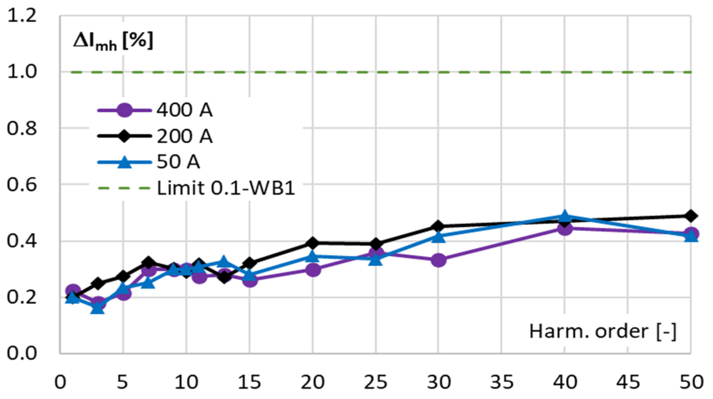
The values of the percentage of the measured value errors determined for the first Rogowski coil by the digital power meter for the harmonic of each distorted current equal to 5% of the main component are presented in
Figure 3. The test current always contains the main component of a frequency of 50 Hz and a single higher harmonic of a frequency from 100 Hz to 2.5 kHz. During the proposed evaluation procedure, the order of the higher harmonic is changed, while the RMS values of the harmonics remain constant. The phase angle between both harmonics is set to 0°.
The values of the percentage of measured value errors are determined for the distorted current main component of a frequency of 50 Hz being equivalent to the RMS values equal to 50 A, 200 A, and 400 A. The above results indicate that the power analyzer with the first RC is characterized by the current harmonic percentage of measured value errors well below ±1% for higher harmonics of orders up to the 50th order. Therefore, this requirement of the standard IEC 61000-4-7 for the class I or II measuring apparatus ±5% presented in
Table 1 is satisfied in the entire tested frequency range of the higher harmonics of the distorted current. Moreover, the requirements of the standards IEC 61869-10 and IEC 61869-1 for the 0.1-WB1 accuracy class are also fulfilled for higher harmonics of the distorted current with the main frequency equal to 50 Hz for the frequency range extended during the test to 3000 Hz.
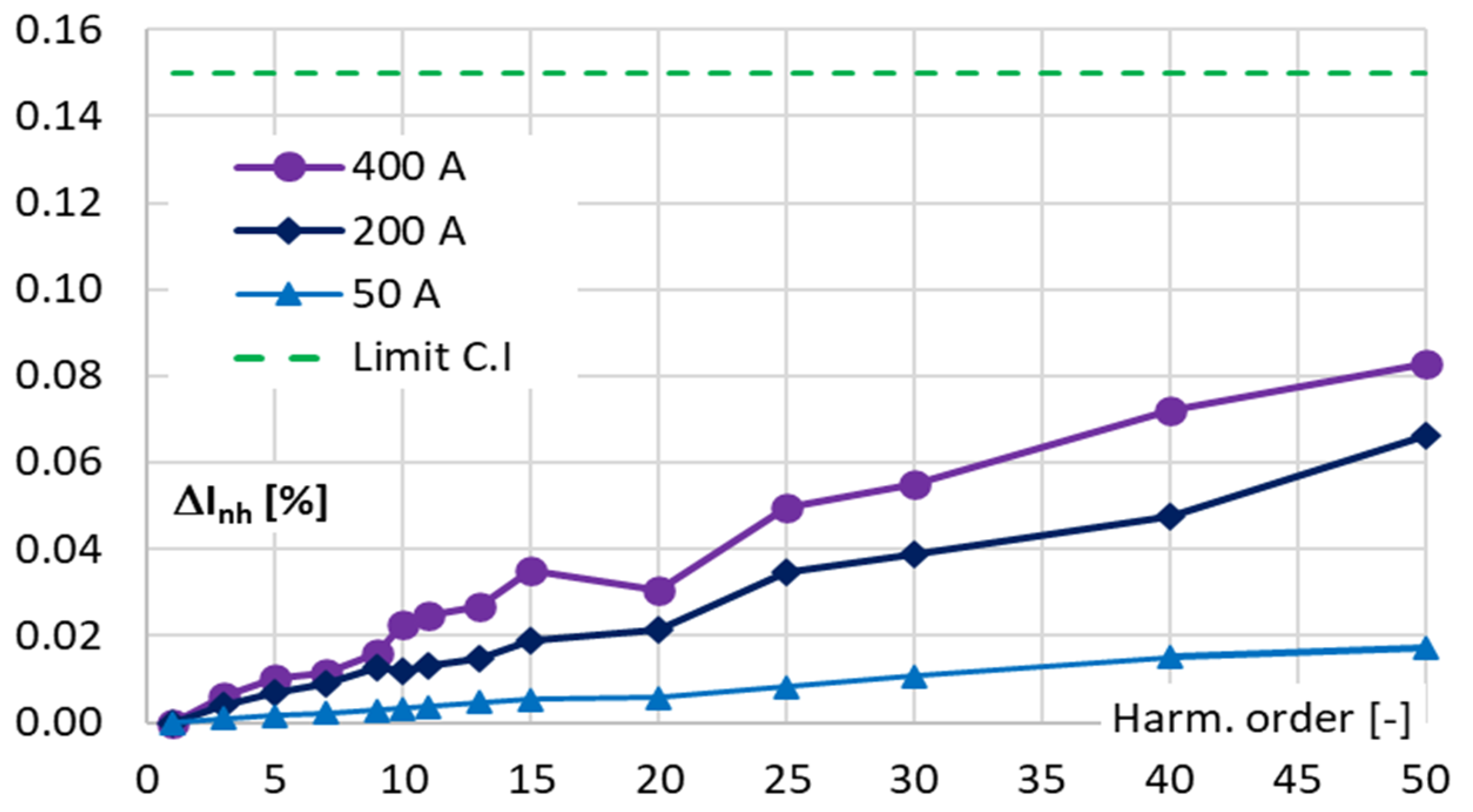
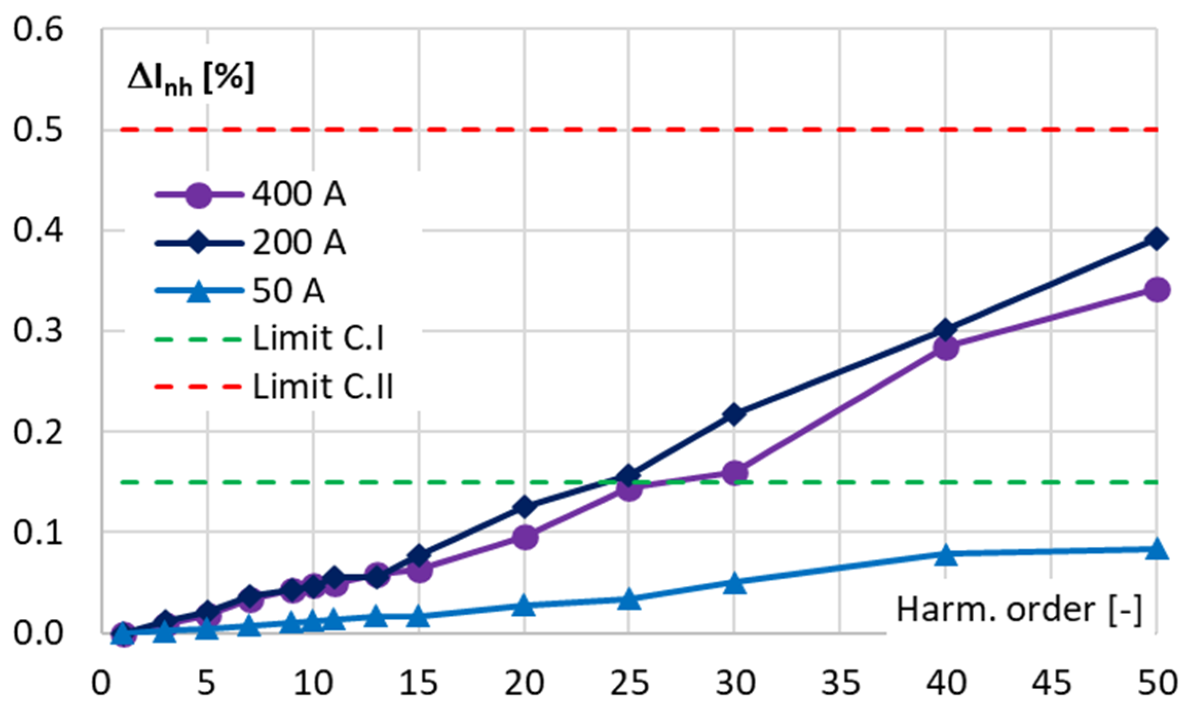
The values of the percentage of nominal value errors determined for the first RC when the RMS value of the higher harmonic is equal to 2% of the main component are presented in
Figure 4.
The results from
Figure 4 show that the determined current harmonic percentage of nominal value errors do not exceed the limiting value equal to ±0.15% for higher harmonics of orders up to the 50th for the distorted current being equivalent to the RMS values equal to 50 A, 200 A, and 400 A. Therefore, the requirement for current accuracy presented in
Table 1 for the class I measuring apparatus is satisfied for all orders of tested higher harmonics.
The values of the percentage of measured value errors determined for the second RC when the RMS value of the higher harmonic is equal to 5% of the main component are presented in
Figure 5.
The values of the percentage of measured value errors are determined for the distorted current main component of a frequency of 50 Hz being equivalent to the RMS values equal to 50 A, 200 A, and 400 A. The above results indicate that the power analyzer with the second Rogowski coil is characterized by the current harmonic percentage of measured value errors below ±1% for higher harmonics of all evaluated frequencies up to 2500 Hz. It results from
Table 1 that this requirement of the standard IEC 61000-4-7 for the class I (and II) measuring apparatus is ensured in the entire required frequency range. Moreover, the requirements of IEC 61869-10 and IEC 61869-1 for the 0.1-WB1 accuracy class are also fulfilled for higher harmonics in the frequency range extended during the test to 3000 Hz.
The values of the percentage of nominal value errors determined for the second RC when the RMS value of the higher harmonic is equal to 2% of the main component are presented in
Figure 6.
The results from
Figure 6 show that the determined current harmonic percentage of nominal value errors do not exceed the limiting value equal to ±0.15% for higher harmonics of orders up to the 25th order for the distorted current being equivalent to the RMS values equal to 200 A and 400 A and up to the 50th order for the distorted current being equivalent to the RMS values equal to 50 A. The increase in the nominal value error, compared with the results for the first RC, is caused by the lower voltage range of the DPM in relation to the measured output voltage from RC, as the current-to-voltage conversion ratio is equal to 100 mV/1 kA instead of 22.5 mV/1 kA. Therefore, the percentage of nominal value errors are lower for the distorted current being equivalent to the RMS values equal to 50 A; this is because the output voltage is equal to 5 mV on the 25 mV input voltage range. In accordance with
Table 1, the requirement of the standard IEC 61000-4-7 for the class I measuring apparatus not to exceed the limiting value equal to ±0.15% is satisfied only up to the frequency of 1250 Hz. The requirement of class II not to exceed the limiting value equal to ±0.50% is met in the entire tested frequency range of the higher harmonics of the distorted current.
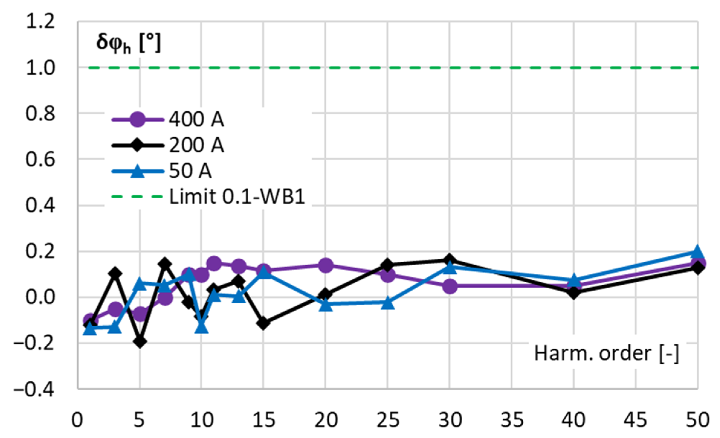
To test the equipment for all requirements defined in the IEC 61869-1, the values of the phase shift (phase displacement) resulting from the conversion of distorted current harmonics by the tested RCs are evaluated. The values determined for each harmonic equal to 5% of the main component of the non-sinusoidal current for the first RC are presented in
Figure 7.
The presented results indicate that the values of the phase shift do not exceed ±0.2° in the entire tested frequency range of the higher harmonics of the distorted current for all of the RMS values of the distorted current. The requirement of the standards IEC 61869-10 and IEC 61869-1 for the 0.1-WB1 accuracy class ±1.0 is satisfied for all tested higher harmonics of the distorted current with the main frequency equal to 50 Hz, even in the extended testing range up to 3000 Hz. Therefore, this RC may be used as the extension of the DPM measuring current range for the evaluation of the power factor for higher harmonics. Moreover, considering also the results presented in
Figure 3, this system may be applied for the measurement of the distorted active and reactive power, as well as for the evaluation of the current harmonic distortion.
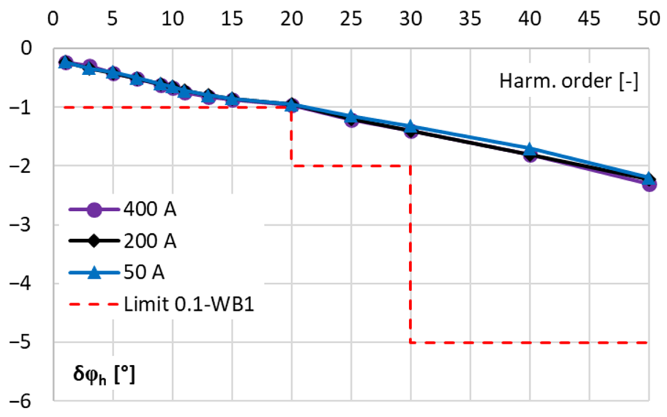
The values of the phase shift determined for the second RC when the RMS value of higher harmonics is equal to 5% of the main component are presented in
Figure 8.
The second RC is characterized by the values of the phase shift that do not exceed ±3° for all tested frequencies of higher harmonics and all RMS values of the distorted current. Moreover, the requirements of the standards IEC 61869-10 and IEC 61869-1 for the 0.1-WB1 accuracy class are satisfied for the extended testing range up to 3000 Hz. Therefore, this Rogowski coil also may be used as the extension of the DPM measuring current range for the measurement of the power factor for higher harmonics. Moreover, considering the results presented in
Figure 5, this device may also be applied to measurements of the distorted active and reactive power, as well as to the evaluation of the current harmonic distortion.
- (b)
The results for the combined transducer composed of the Rogowski coil (RC) and its signal conditioner (SC).
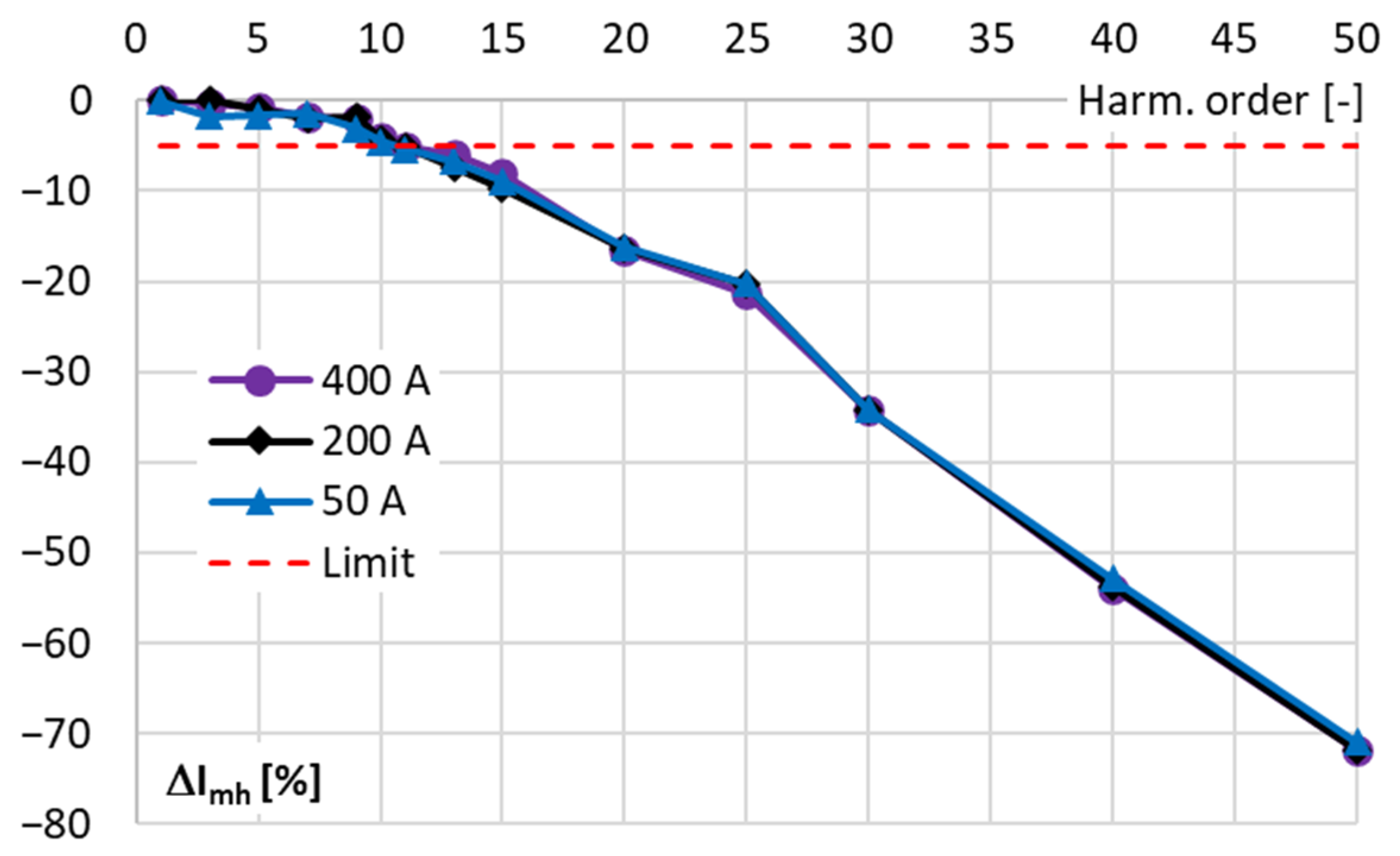
The values of the percentage of measured value errors determined for distorted currents with a single higher harmonic of a frequency from 100 Hz to 2.5 kHz and equal to 5% of the main component by the digital power meter (DPM) for the first RC with its SC are presented in
Figure 9.
The values of the percentage of measured value errors are determined for the distorted current with the main component of a frequency of 50 Hz being equivalent to the RMS values equal to 50 A, 200 A, and 400 A. The above results indicate that the power analyzer with the first Rogowski coil and its signal conditioner is characterized by the current harmonic percentage of measured value errors below ±5% for higher harmonics of orders up to 10th order. Therefore, this requirement of the standards IEC 60044-8 and IEC 61000-4-7 for the class I or II measuring apparatus presented in
Table 1 is satisfied only up to the frequency equal to 500 Hz. Moreover, the requirements defined in the standard IEC 61869-1 for the 0.5-WB1 accuracy class are also fulfilled for higher harmonics of the distorted current with the main frequency equal to 50 Hz only up to their 10th order.
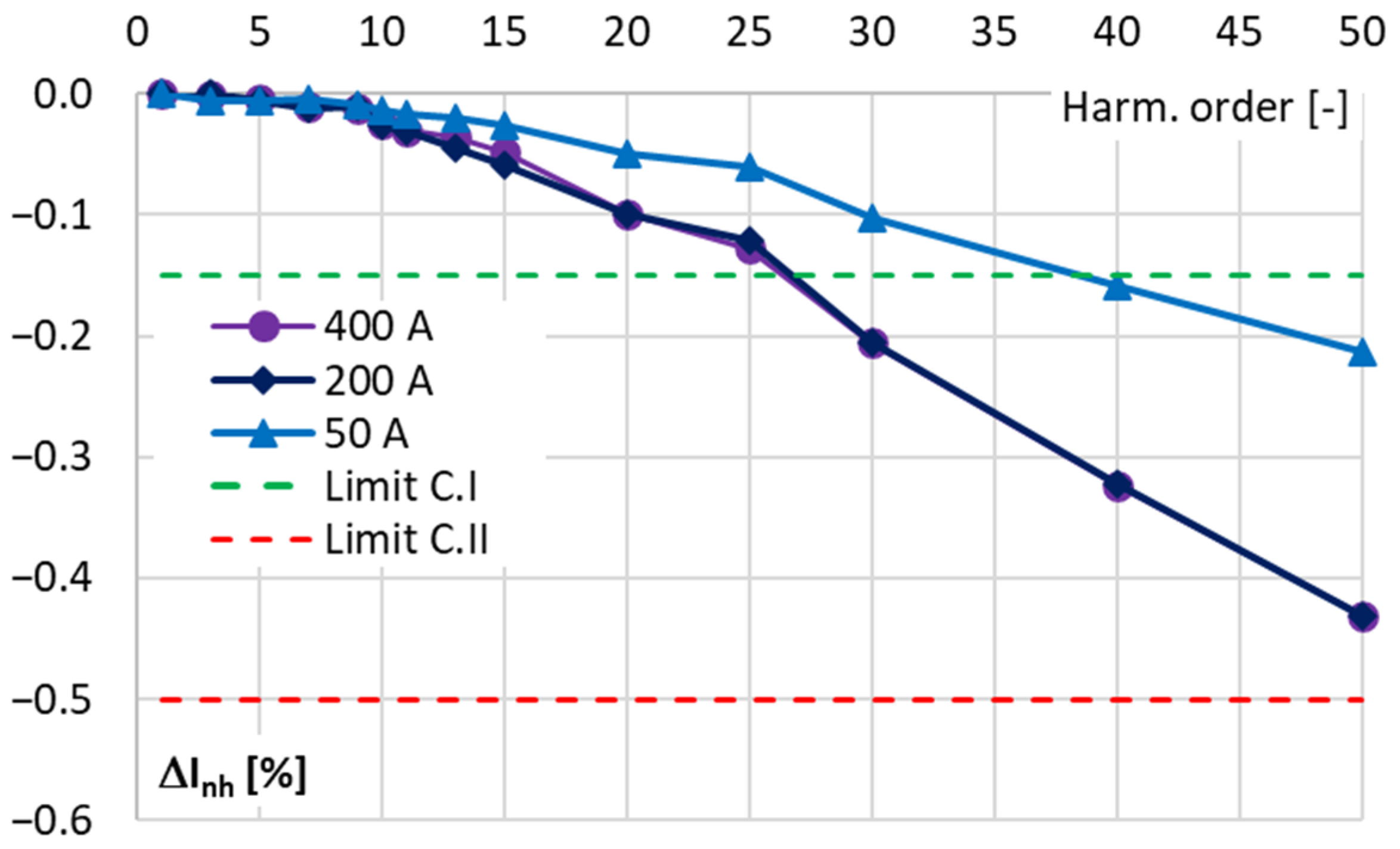
The percentage of the nominal value errors of the conversion of the distorted currents with a single higher harmonic of frequency from 100 Hz to 2.5 kHz being equal to 2% of its main component by the DPM with the first RC and its SC are presented in
Figure 10.
The results from
Figure 10 show that the determined current harmonic percentage nominal value errors did not exceed the limiting value equal to ±0.15% for higher harmonics of orders up to the 27th for the distorted current being equivalent of the RMS values equal to 200 A and 400 A; additionally, up to the 37th order, when the distorted current is equivalent to the RMS values equal to 50 A. Therefore, in accordance with
Table 1, the requirement of the standard IEC 61000-4-7 for the class I measuring apparatus not to exceed the limiting value equal to ±0.15% is satisfied only up to a frequency of 1350 Hz. The requirement of class II not to exceed the limiting value equal to ±0.50% is met in the entire tested frequency range of the higher harmonics of the distorted current.
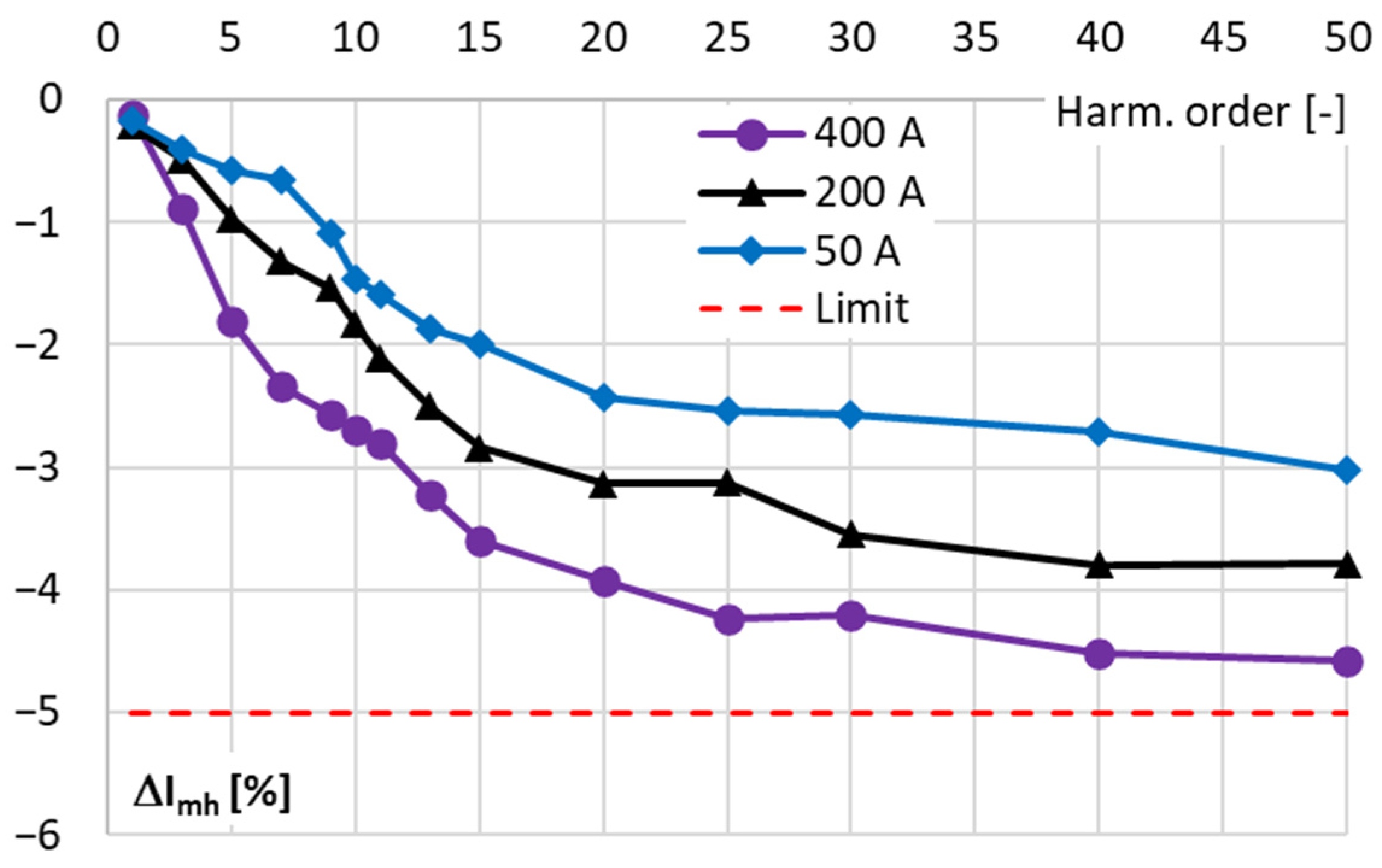
The values of the percentage of measured value errors are determined for each harmonic of the distorted current equal to 5% of the main component by the digital power meter for the second RC with its SC; this is presented in
Figure 11. The results are obtained for the distorted current main component of a frequency of 50 Hz being equivalent to the RMS values equal to 50 A, 200 A, and 400 A.
The above results indicate that the power analyzer with the second RC and its SC (combined transducer) is characterized by the current harmonic percentage of measured value errors below ±5% for higher harmonics of all evaluated frequencies up to 2500 Hz. It results from
Table 1 that this requirement of the standards IEC 60044-8 and IEC 61000-4-7 for the class I (and II) measuring apparatus is ensured in the entire required frequency range. Moreover, the requirements defined in the standard IEC 61869-1 for the 0.5-WB1 accuracy class are also fulfilled for higher harmonics of the distorted current with the main frequency equal to 50 Hz for the frequency range extended during the test to 3000 Hz.
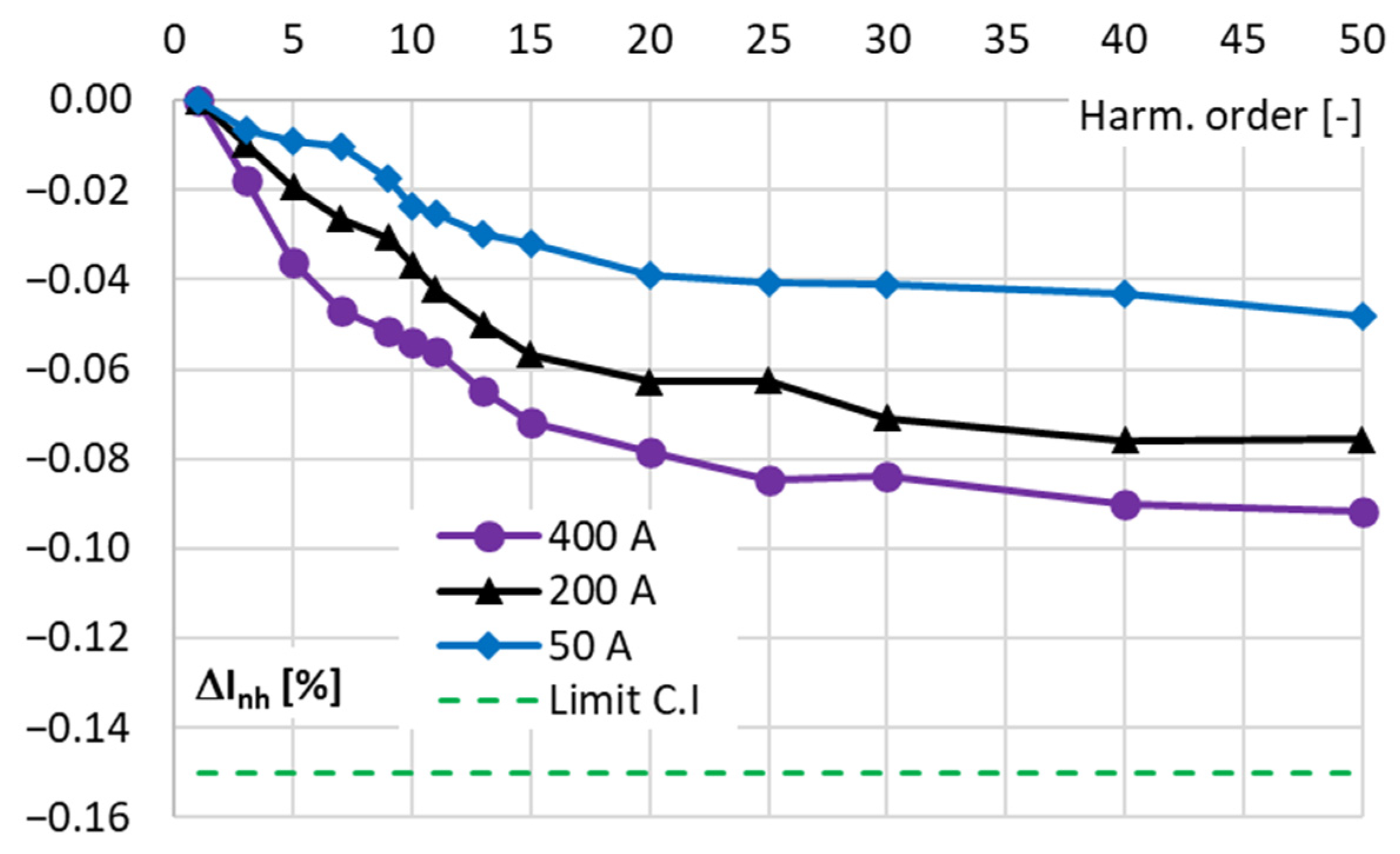
The percentage of nominal value errors determined for each harmonic of the distorted current equal to 2% of the main component by the DPM for the second RC with its SC are presented in
Figure 12.
The results from
Figure 12 indicate that the determined values of the current harmonic percentage of nominal value errors do not exceed the limiting value equal to ±0.15% for the class I measuring apparatus in the entire tested frequency range of the higher harmonics of the distorted current. Therefore, in accordance with
Table 1, this requirement of the standard IEC 61000-4-7 is fulfilled.
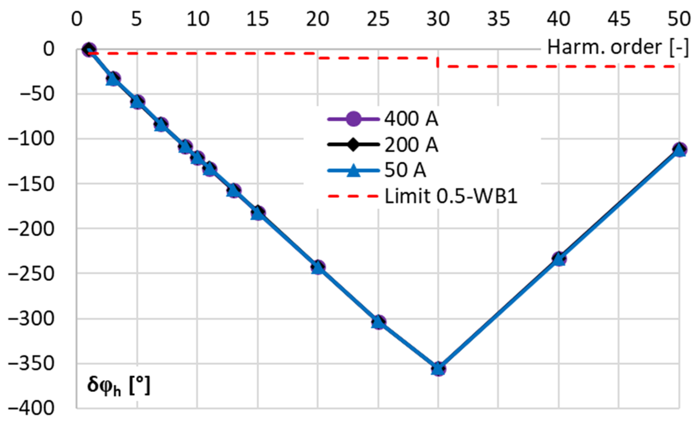
Additionally, to the requirement defined in the standard IEC 61000-4-7 but in compliance with the standard IEC 61869-1, the phase shift of each harmonic resulting from the conversion of the distorted current by tested combined transducers is evaluated. The values determined for each harmonic of the distorted current with their percentage level equal to 5% of the main component by the DPM for the first RC with its SC are presented in
Figure 13.
The presented results indicate, e.g., that the value of the phase shift for fifth-order higher harmonic exceeds ±50°, while for 10th, it is above ±120°. Therefore, this system may not be used for the extension of the DPM measuring current range for the measurement of distorted active and reactive power. Moreover, the current higher harmonics of order above the 30th order are additionally shifted by the first Rogowski coil with the signal conditioner above ±360°. The requirements defined in the standard IEC 61869-1 for the 0.5-WB1 accuracy class are not satisfied for any higher harmonic of the distorted current with the main frequency equal to 50 Hz and even more so for 60 Hz or any higher frequency.
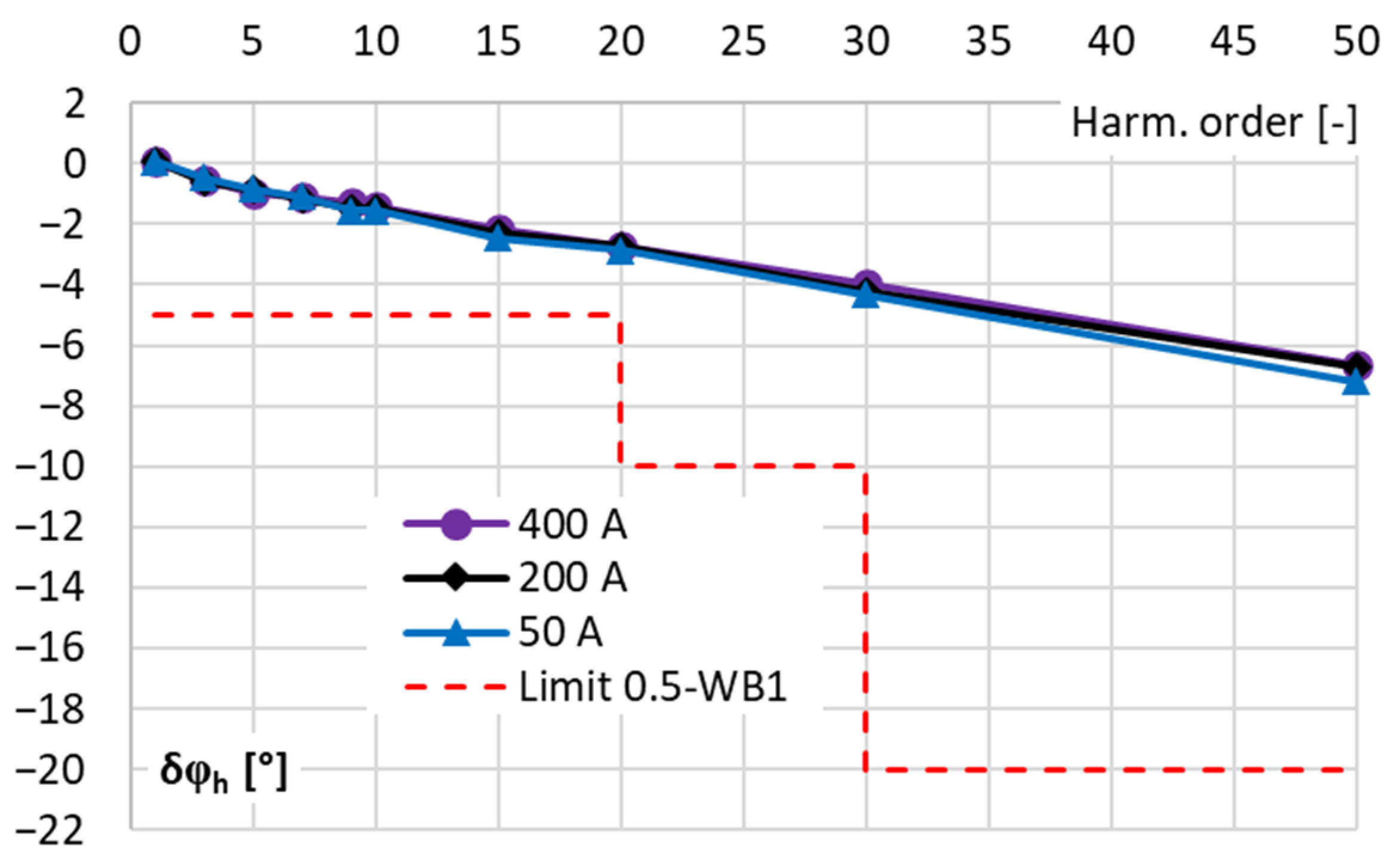
The phase shift determined for each harmonic of the distorted current with its percentage level equal to 5% of the main component by the DPM for the second RC with its SC are presented in
Figure 14.
The second combined transducer is characterized by the values of the phase shift that do not exceed ±8° in the entire tested frequency range for all RMS values of the distorted current. The requirements of the 0.5-WB1 accuracy class are also satisfied. Nevertheless, this system should not also be used as the extension of the DPM measuring current range for distorted active and reactive power, as well as for the evaluation of the power factor for higher harmonics. It will cause a significant deterioration of its accuracy resulting from the conversion error and phase shift and their important influence on the RMS value and phase angle of current higher frequency components.


