
High-Frequency Modeling and Analysis of Single-Layer NiZn Ferrite Inductors for EMI Filtering in Power Electronics Applications


Abstract
1. Introduction
2. Analysis of NiZn Inductors and Circuit Models
2.1. Electromagnetic Behavior of NiZn Inductor
2.2. Derivation of HF Circuit Model
2.2.1. Case 1: Incomplete Uniform Windings
2.2.2. Case 2: Sub-Complete or Complete Uniform Windings
3. Physical Parameter Acquisition
3.1. Complex Inductance Modeling
3.2. Static Capacitance Modeling
3.2.1. Calculation of Turn-to-Turn Capacitance Ctt
3.2.2. Calculation of Turn-to-Core Capacitance Ctc
3.2.3. Calculation of Static Core Capacitance Ccs
3.2.4. Calculation of Static Core Capacitance Che Between Head and End Turns
4. Experiment Verification
5. Conclusions
Author Contributions
Funding
Data Availability Statement
Conflicts of Interest
References
- Zhang, Y.; Li, Q.; Jiang, D. A Motor CM Impedance Based Transformerless Active EMI Filter for DC-Side Common-Mode EMI Suppression in Motor Drive System. IEEE Trans. Power Electron. 2020, 35, 10238–10248. [Google Scholar] [CrossRef]
- Li, Q.; Zhao, X.; Jiang, D.; Chen, J. Voltage Ripple Control of Flying Capacitor Three-Level Inverter With Variable Switching Frequency PSPWM. IEEE Trans. Ind. Electron. 2022, 69, 3313–3323. [Google Scholar] [CrossRef]
- Khowja, M.R.; Gerada, C.; Vakil, G.; Patel, C.; Odhano, S.A.; Walker, A.; Wheeler, P. Novel Permanent Magnet Synchronous Motor With Integrated Filter Inductor, Using Motor’s Inherent Magnetics. IEEE Trans. Ind. Electron. 2021, 68, 5638–5649. [Google Scholar] [CrossRef]
- Perreault, D.J.; Hu, J.; Rivas, J.M.; Han, Y.; Leitermann, O.; Pilawa-Podgurski, R.C.; Sagneri, A.; Sullivan, C.R. Opportunities and challenges in very high frequency power conversion. In Proceedings of the 2009 Twenty-Fourth Annual IEEE Applied Power Electronics Conference and Exposition, Washington, DC, USA, 15–19 February 2009; pp. 1–14. [Google Scholar]
- Jie, H.; Gao, S.-P.; Zhao, Z.; Fan, F.; Sasongko, F.; Gupta, A.K.; See, K.Y. VNA-Based Fixture Adapters for Wideband Accurate Impedance Extraction of Single-Phase EMI Filtering Chokes. IEEE Trans. Ind. Electron. 2023, 70, 7821–7831. [Google Scholar] [CrossRef]
- Ojeda-Rodríguez, Á.; Bernal-Méndez, J.; Martín-Prats, M.A. Modal Theory and Approach for Accurate Characterization of Common-Mode Chokes. IEEE Trans. Power Electron. 2023, 38, 10516–10529. [Google Scholar] [CrossRef]
- Heldwein, M.L.; Dalessandro, L.; Kolar, J.W. The Three-Phase Common-Mode Inductor: Modeling and Design Issues. IEEE Trans. Ind. Electron. 2011, 58, 3264–3274. [Google Scholar] [CrossRef]
- Li, Q.; Xie, B.; Zhang, Y.; Ma, J.; Yuan, C. A General Analytical Model of Single-Layer Common-Mode Chokes. IEEE Trans. Power Electron. 2024, 39, 6591–6596. [Google Scholar] [CrossRef]
- Kovacic, M.; Hanic, Z.; Stipetic, S.; Krishnamurthy, S.; Zarko, D. Analytical Wideband Model of a Common-Mode Choke. IEEE Trans. Power Electron. 2012, 27, 3173–3185. [Google Scholar] [CrossRef]
- Jie, H.; Zhao, Z.; Li, H.; Wang, C.; Chang, Y.; See, K.Y. Characterization and Circuit Modeling of Electromagnetic Interference Filtering Chokes in Power Electronics: A Review. IEEE Trans. Power Electron. 2024. [Google Scholar] [CrossRef]
- Jie, H.; Zhao, Z.; Chang, Y.; Zeng, Y.; Fan, F.; Sasongko, F.; Gupta, A.K.; See, K.Y. High-Frequency Impedance Modeling of Nanocrystalline Common-Mode Chokes Using Mixed-Mode Theory and Improved Multistage RLC Iteration Circuit. IEEE Trans. Ind. Electron. 2024. [Google Scholar] [CrossRef]
- Jie, H.; Zhao, Z.; Fan, F.; Zeng, Y.; Sasongko, F.; Gupta, A.K.; See, K.Y. High-Precision Broadband Impedance Measurements of Three-Phase Common-Mode Chokes Using Single-Port Circuit De-Embedding and Three-Port Network Calibration Methods. IEEE Trans. Ind. Electron. 2024, 71, 8248–8258. [Google Scholar] [CrossRef]
- Zhang, J.; Ding, Y.; Wang, L. Method for Measuring Permeability of Ferrite Core. Electr. Meas. Instrum. 2009, 46, 1–4. [Google Scholar]
- Qin, L.; Ouyang, B.; Xin, M.; Gao, L. Measurement of Inductance of Toroidal Cores Based on Switching Circuits. Electr. Meas. Instrum. 2013, 50, 38–41. [Google Scholar]
- Moonen, N.; Vogt-Ardatjew, R.; Roc’h, A.; Leferink, F. 3-D Full-Wave High Frequency Common Mode Choke Modeling. IEEE Trans. Electromagn. Compat. 2020, 62, 707–714. [Google Scholar] [CrossRef]
- Jie, H.; Zhao, Z.; Fan, F.; Chang, Y.; Sasongko, F.; Gupta, A.K.; See, K.Y. Characterization and Modeling of Single-Phase Common-Mode Chokes via Finite-Element Analysis. In Proceedings of the IECON 2023-49th Annual Conference of the IEEE Industrial Electronics Society, Singapore, 16–19 October 2023; pp. 1–6. [Google Scholar]
- Manterola, A.M.; Angulo, L.M.D.; Bravo, A.G.; Tekbaş, K.; Tijero, M.; Moreno, R.; Garcia, S.G. Impedance Modeling of Common Mode Ferrite Chokes Using Transmission Line Theory. IEEE Trans. Power Electron. 2024, 39, 4224–4233. [Google Scholar] [CrossRef]
- Tan, W. Modeling and Design of Passive Planar Components for EMI Filters. Ph.D. Dissertation, Ecole Centrale de Lille, Lille, France, 2012. [Google Scholar]
- Huang, R.; Zhang, D.; Tseng, K.-J. Determination of Dimension-Independent Magnetic and Dielectric Properties for Mn–Zn Ferrite Cores and Its EMI Applications. IEEE Trans. Electromagn. Compat. 2008, 50, 597–602. [Google Scholar] [CrossRef]
- Zhang, D.; Huang, R. Calculation of effective impedance of common-mode choke made of Mn-Zn ferrite. In Proceedings of the 2006 17th International Zurich Symposium on Electromagnetic Compatibility, Singapore, 28 February–3 March 2006; pp. 391–394. [Google Scholar]
- Yamada, S.; Otsuki, E.; Otsuka, T. AC resistivity of Mn-Zn ferrites. In Proceedings of the Thirteenth International Telecommunications Energy Conference—INTELEC 91, Kyoto, Japan, 5–8 November 1991; pp. 703–708. [Google Scholar]
- Li, Y.; Wang, S. Modeling and Increasing the High-Frequency Impedance of Single-Layer Mn-Zn Ferrite toroidal Inductors With Electromagnetic Analysis. IEEE Trans. Power Electron. 2021, 36, 6943–6953. [Google Scholar] [CrossRef]
- Shen, Z.; Chen, W.; Zhao, H.; Jin, L.; Hanson, A.J.; Perreault, D.J.; Sullivan, C.R.; Blaabjerg, F.; Wang, H. Core Energy Capacitance of NiZn Inductors. IEEE Trans. Power Electron. 2023, 38, 4235–4240. [Google Scholar] [CrossRef]
- Salomez, F.; Videt, A.; Idir, N. Modeling and Minimization of the Parasitic Capacitances of Single-Layer toroidal Inductors. IEEE Trans. Power Electron. 2022, 37, 12426–12436. [Google Scholar] [CrossRef]
- Pasko, S.W.; Kazimierczuk, M.K.; Grzesik, B. Self-Capacitance of Coupled Toroidal Inductors for EMI Filters. IEEE Trans. Electromagn. Compat. 2015, 57, 216–223. [Google Scholar] [CrossRef]
- Shen, Z.; Wang, H.; Shen, Y.; Qin, Z.; Blaabjerg, F. An Improved Stray Capacitance Model for Inductors. IEEE Trans. Power Electron. 2019, 34, 11153–11170. [Google Scholar] [CrossRef]
- TDK. Ferrites and Accessories. Technical Report. 2023. Available online: https://www.tdk-electronics.tdk.com/inf/80/db/fer/r_50_0_30_0_20_0.pdf (accessed on 1 May 2023).


| Case 1 | Case 2 | Case 3 | |
|---|---|---|---|
| Winding form | Partial wound | Partial wound | Fully wound |
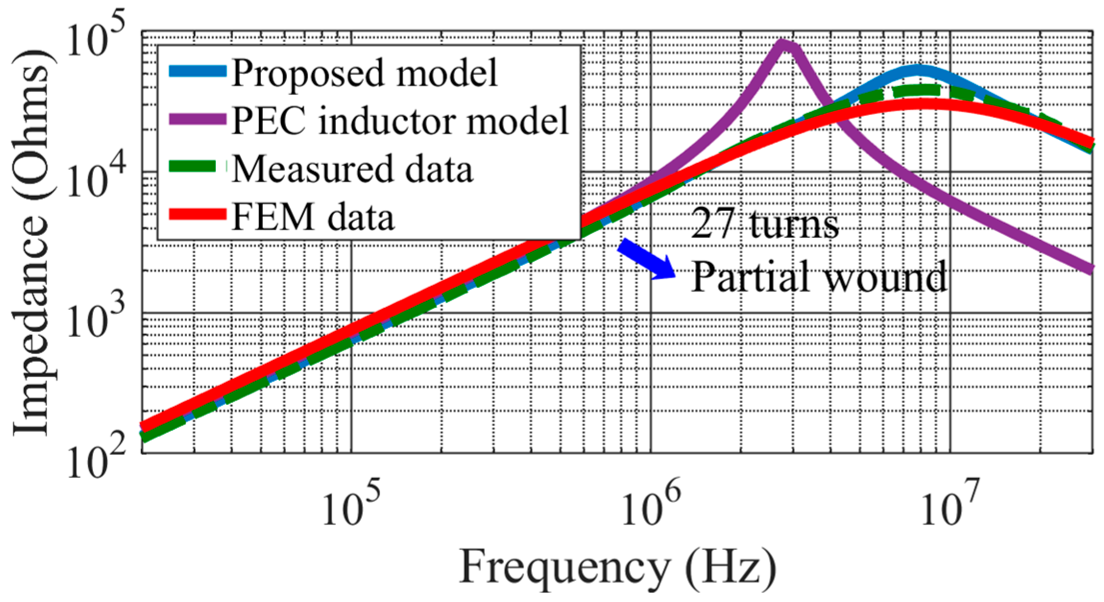
| Number of turns | 37 | 27 | 27 |
| Dimension | 50/30/20(mm) | ||
| Core permeability | 8 × 10²–2 × 10² | ||
| Core permittivity | 12 | ||
| Core insulation | 0 mm | ||
| Winding insulation | 0.1 mm | ||
| Equivalent turn-to-core distance | 0.2 mm | ||
| Diameter of winding | 1 mm | ||
Disclaimer/Publisher’s Note: The statements, opinions and data contained in all publications are solely those of the individual author(s) and contributor(s) and not of MDPI and/or the editor(s). MDPI and/or the editor(s) disclaim responsibility for any injury to people or property resulting from any ideas, methods, instructions or products referred to in the content. |
© 2024 by the authors. Licensee MDPI, Basel, Switzerland. This article is an open access article distributed under the terms and conditions of the Creative Commons Attribution (CC BY) license (https://creativecommons.org/licenses/by/4.0/).
Share and Cite
Li, Y.; Zhang, Z.; Yu, J.; Liu, Z.; Li, Q. High-Frequency Modeling and Analysis of Single-Layer NiZn Ferrite Inductors for EMI Filtering in Power Electronics Applications. Energies 2024, 17, 5657. https://doi.org/10.3390/en17225657
Li Y, Zhang Z, Yu J, Liu Z, Li Q. High-Frequency Modeling and Analysis of Single-Layer NiZn Ferrite Inductors for EMI Filtering in Power Electronics Applications. Energies. 2024; 17(22):5657. https://doi.org/10.3390/en17225657
Chicago/Turabian StyleLi, Yang, Zhaohui Zhang, Jinyun Yu, Zhiqiang Liu, and Qiao Li. 2024. "High-Frequency Modeling and Analysis of Single-Layer NiZn Ferrite Inductors for EMI Filtering in Power Electronics Applications" Energies 17, no. 22: 5657. https://doi.org/10.3390/en17225657
APA StyleLi, Y., Zhang, Z., Yu, J., Liu, Z., & Li, Q. (2024). High-Frequency Modeling and Analysis of Single-Layer NiZn Ferrite Inductors for EMI Filtering in Power Electronics Applications. Energies, 17(22), 5657. https://doi.org/10.3390/en17225657