Article

Energy Advantages and Thermodynamic Performance of Scheffler Receivers as Thermal Sources for Solar Thermal Power Generation

by
Paolo Iodice
1,*,
Amedeo Amoresano
1,
Giuseppe Langella
1 and
Francesco Saverio Marra
2
1
Dipartimento di Ingegneria Industriale, Università Degli Studi di Napoli Federico II, Via Claudio 21, 80125 Naples, Italy
2
Istituto di Scienze e Tecnologie per l’Energia e la Mobilità Sostenibili, Consiglio Nazionale delle Ricerche, Via Guglielmo Marconi 4, 80125 Naples, Italy
*
Author to whom correspondence should be addressed.
Energies 2024, 17(21), 5393; https://doi.org/10.3390/en17215393
Submission received: 8 July 2024 / Revised: 22 October 2024 / Accepted: 25 October 2024 / Published: 30 October 2024
(This article belongs to the Section A2: Solar Energy and Photovoltaic Systems)

Abstract

:
This article examines the prospects of Scheffler solar receivers integrated into renewable energy power plants for civil applications. This kind of solar receiver can offer satisfactory energetic performance with acceptable energy conversion efficiency when compared to other technologies to harness solar energy since the high-quality focal receiver can reduce heat losses also supposing great levels of evaporation temperature. In this research, energetic optimization and a broad assessment of Scheffler-type solar receivers are thoroughly conducted for variable sun radiation and considering a broad range of working conditions. To achieve this goal, thermodynamic optimization of the chief factors was attained via a numerical model which calculated the energy efficiency of the Scheffler solar receiver at part-load working conditions by computing all energy losses negatively affecting the heat exchange phase in the cavity receiver. The results obtained in this study show that the solar collector efficiencies of Scheffler receivers appear more promising than that of usual parabolic trough collectors; moreover, Scheffler receivers persisted with less sensitivity to reductions in solar radiation intensity. For these reasons, solar power systems based on Scheffler-type systems can be used from tens to hundreds of kW to ensure the energetic supply of small urban settlements with acceptable efficiency, optimistic investments, simple construction and reduced overall sizes.

1. Introduction

Presently, fossil fuels remain the major font of the world’s energy supply with related environmental problems (above all, pollutant emissions and global warming) while, at the same time, world energy request is expected to increase by almost 30% in the next decades owing to global population growth 1. For these reasons, currently, a lot of research is being conducted on new technological solutions to harness renewable energy sources [1,2].
In the last years, solar energy has attracted rising interest worldwide since it represents the most ample and available renewable energy resource [3]. Regarding this, solar thermal power generation and photovoltaic are two recognised systems which can be adopted to substitute standard fossil fuel-powered generating facilities for power up to 500 kW [4]. Yet, currently, it is well known that the large-scale diffusion of photovoltaic power generation is slowed down due to both excessive production costs and unsatisfactory energetic conversion efficiency in exploitation of solar energy [5].
Presently, in real applications, several low-medium temperature solar systems are based on organic fluids in Rankine cycles [6] to assure high specific energy during the expansion process even when the pressure levels are reduced [7]. However, the energy efficiency of solar electricity generation systems (SEGS) based on an organic Rankine cycle is hampered by unsatisfactory thermodynamic performance at temperatures exceeding 473 K. In fact, in real applications, solar plants based on organic fluids in combination with a Rankine cycle imply a heat exchange between two fluids, clearly involving an exergetic destruction of the available thermal power [8]. Moreover, organic Rankine cycles are penalised by numerous obstacles regarding thermal instability [9], flammability and the toxicity of organic fluids [10]. With all these operating restrictions, solar energy may be not easy to utilize in real applications [11].
All the environmental limitations of organic Rankine cycles have boosted the growth of concentrated solar power (CSP) plants [12]. Presently, CSP plants with DSG (direct steam generation) are largely based on parabolic trough collectors (PTCs) and linear Fresnel reflectors that represent recognised technologies in exploitation of solar power [13]. In effect, these solar systems provide about 85% of the whole capacity of real solar thermal power systems [14]. Nonetheless, declines in solar power collector efficiency with rising evaporation temperature prove to be very high in PTC systems because of non-negligible convective and radiative thermal losses [15]. Furthermore, in solar power plants based on PTCs, there is significant variation in solar collector efficiency with fluctuating solar intensity [16], so that the reduction in solar irradiance caused by unfavorable weather conditions can significantly reduce the mechanical power delivered by such SEGS [17].
Being stimulated by such critical matters, the present research proposes the Scheffler (SC) solar paraboloid concentrator as a heat source in the new solar-powered cascade Rankine cycle plant, where water is used as both heat transfer and operating fluid. Such renewable energy power plants could prove very promising for civil applications, ensuring energetic supplies of small urban settlements (net power from 10 to 100 kW), with acceptable efficiency, optimistic investments, simple construction and reduced overall dimensions [18].
The SC solar receivers, which are based on a single fixed solar paraboloid concentration system, were originally proposed and designed by Wolfgang Scheffler in the 1980s with the purpose of application all over the world, but mostly in emerging states [19]. The main aim was to design an excellent reflector that involves a simple structure and a cheap tracking mechanism so that it could be simply operated and maintained with reduced investments [20]. Actually, Scheffler-type solar receivers represent low-cost lightweight devices: installation and manufacturing costs of a sole SC solar system are always less than EUR 10,000 [21]. Moreover, the SC solar receiver can perform better than PTC [22], owing to the excellent efficiency and compactness of the focal receiver that can minimize convective and radiative heat losses. Also, the decline in solar energy collector efficiency with reducing sun radiation appears more acceptable for Scheffler receivers when compared with PTC solar receivers [23].
However, albeit SC solar receivers were originally proposed for sterilization, distillation and cooking applications, several studies have proven that these solar systems could also be adopted in DSG solar thermal power plants with DSG [24]. In effect, renewable energy power systems based on Scheffler-type solar receivers as thermal source could represent an original and promising system configuration. In this regard, although the energy performance of analogous solar power plants was assessed in other scientific publications [21,25,26,27], nowadays, Scheffler receivers are rarely used for solar thermal power system applications. Hence, as a favourable technological solution used in solar power systems with DSG, an in-depth analysis on the energetic performance of Scheffler receivers for variable working conditions is necessary. As is well known, really, the solar-to-electricity efficiency of each SEGS always depends on the energetic performance of its key components, so the mathematical model and basic principles for the SC solar receivers’ part-load behaviour have to be investigated.
For this reason, to conduct the energy evaluation of the solar paraboloid receiver proposed in this research, a thermodynamic model for SC system part-load behavior was evaluated, so assessing each energy loss that could affect the thermal transmission process in the cavity. Then, this thermodynamic model was implemented in a Matlab numerical code, so that the numeric optimization of the chief thermodynamic variables was conducted at part-load working states. As a result of mathematical simulations based on the proposed thermodynamic model, the energetic performance of such a solar receiver was evaluated by assessing variations in solar energy collector efficiency with both sun energy intensity and evaporation temperature. Moreover, in this paper, a comparison between Scheffler and PTC solar systems was conducted about the energy performance and solar power collector efficiencies.
It is obvious that a deep comprehension of the influence of the main thermodynamic parameters in the energetic assessment of the Scheffler solar system is necessary for the construction and marketing phases of these solar receivers adopted in innovative CSP plants. However, as thoroughly explained in the next sections of this study, Scheffler-type receivers can become a favorable and profitable technology for optimal use in DSG solar power plants.

2. Organization of the Manuscript

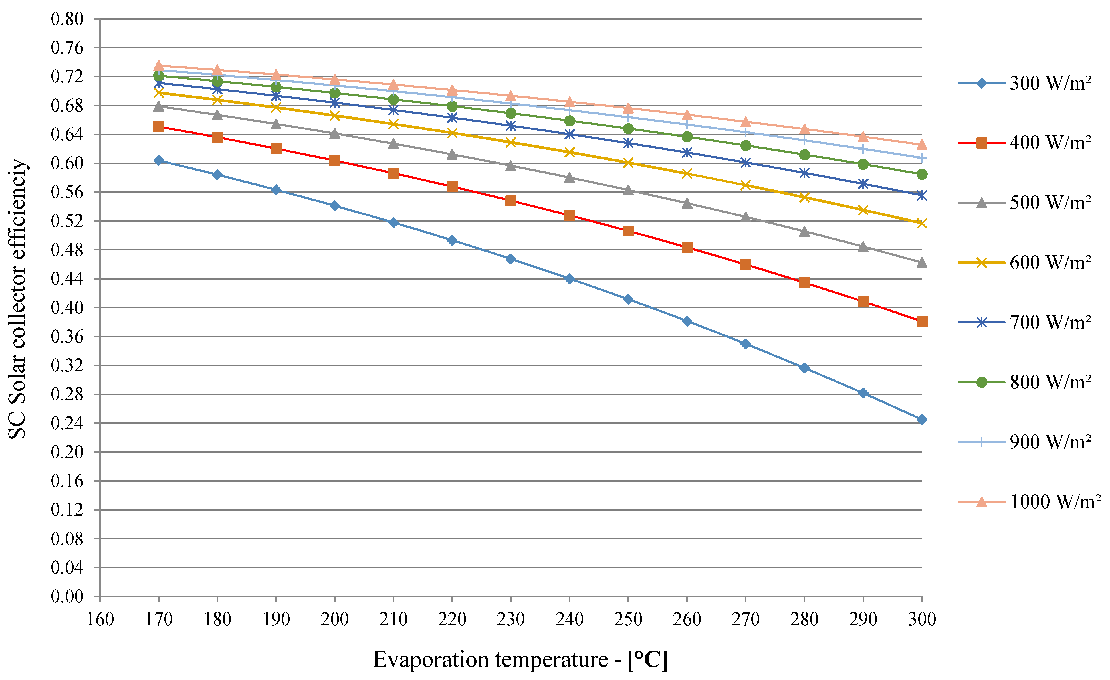
  • In this paper, first, to calculate energy performance of Scheffler-type solar receivers at part-load operating conditions, a numerical model is presented which computes all energy losses affecting the thermal transfer phase in the cavity receiver. Then, solar power collector energy efficiency obtained via the proposed numerical model could be calculated for variable sun radiation and under a wide range of working conditions.
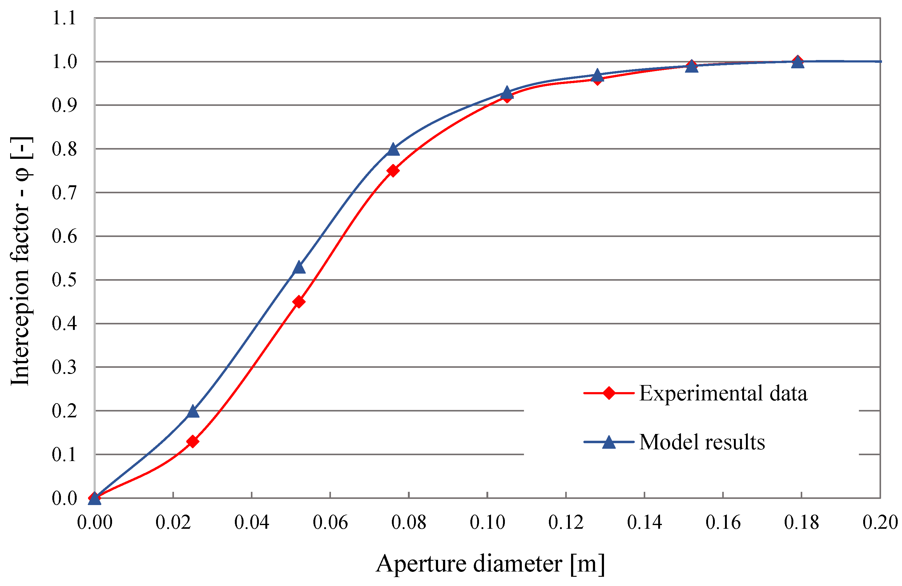
  • After presenting this thermal model, its validation procedure was conducted using test data from relevant scientific literature.
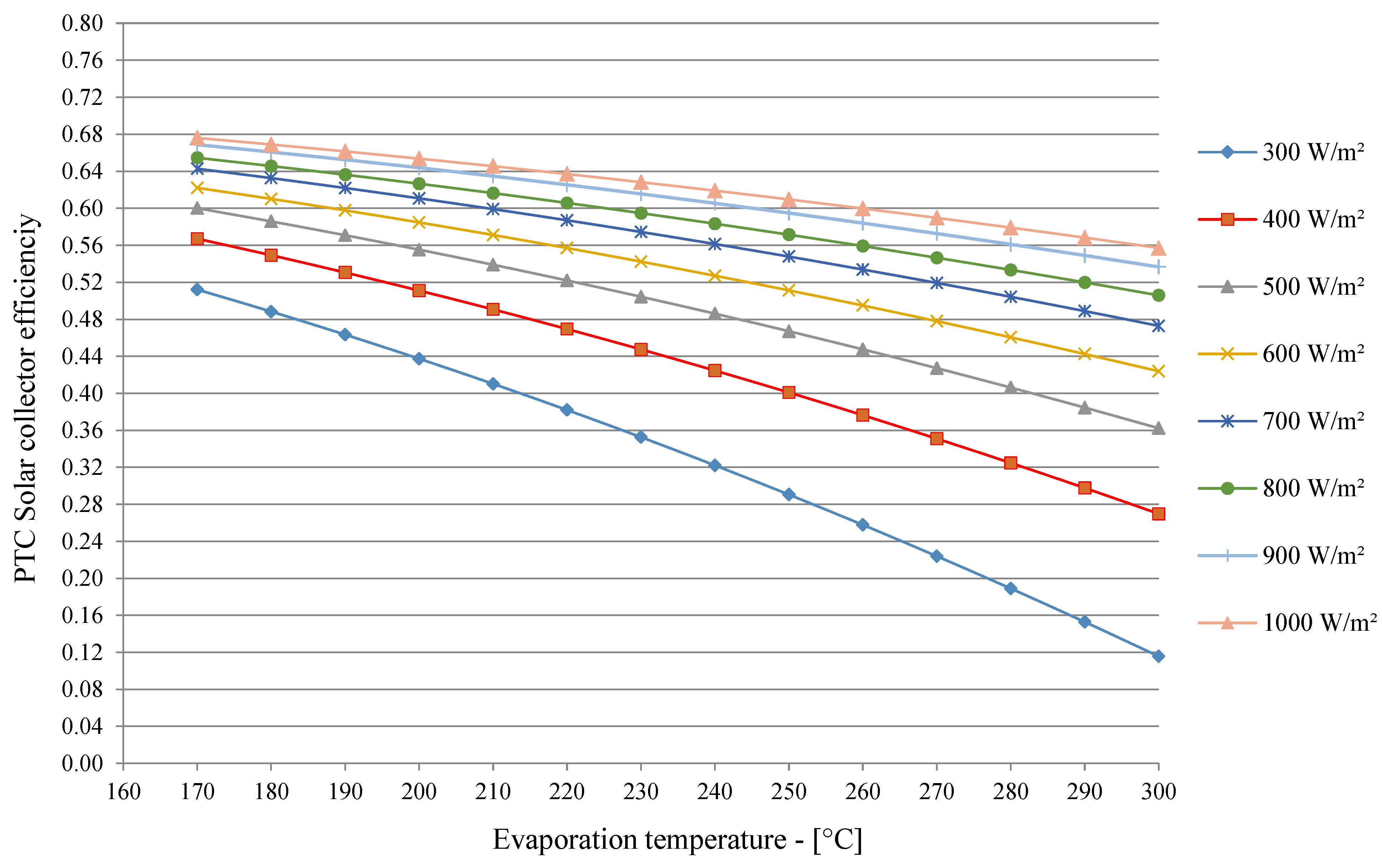
  • Subsequently, to evaluate a performance analysis between the Scheffler-type solar receiver and conventional PTC system, basic equations and thermodynamic models were also established on the latter solar system.
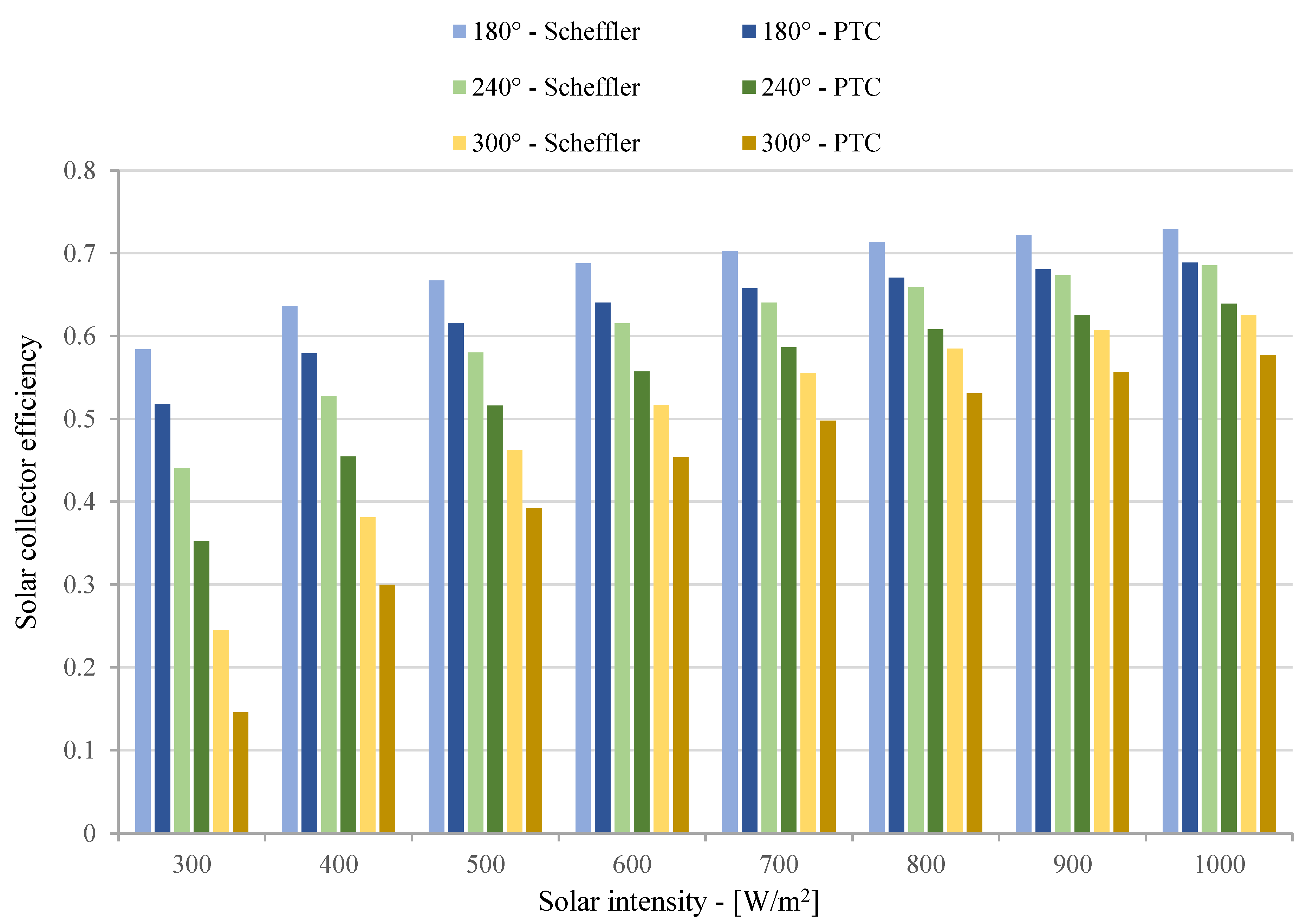
  • Lastly, as a result of mathematical simulations based on such thermodynamic models, a comparison between Scheffler and PTC solar systems was conducted in relation to energy performance and solar power collector efficiency. The main results obtained for these two kinds of solar systems were then settled and compared.

3. Modelling

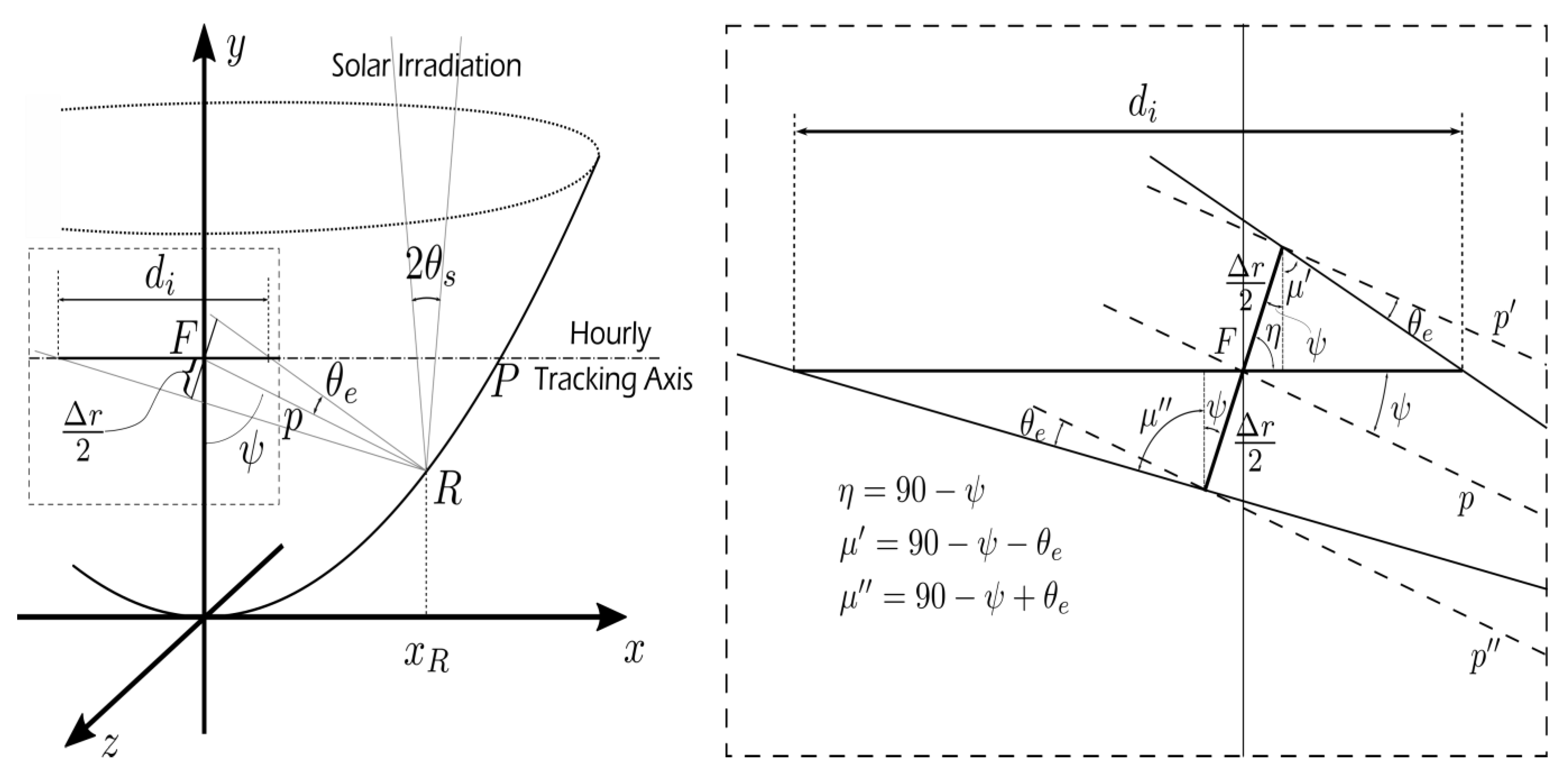
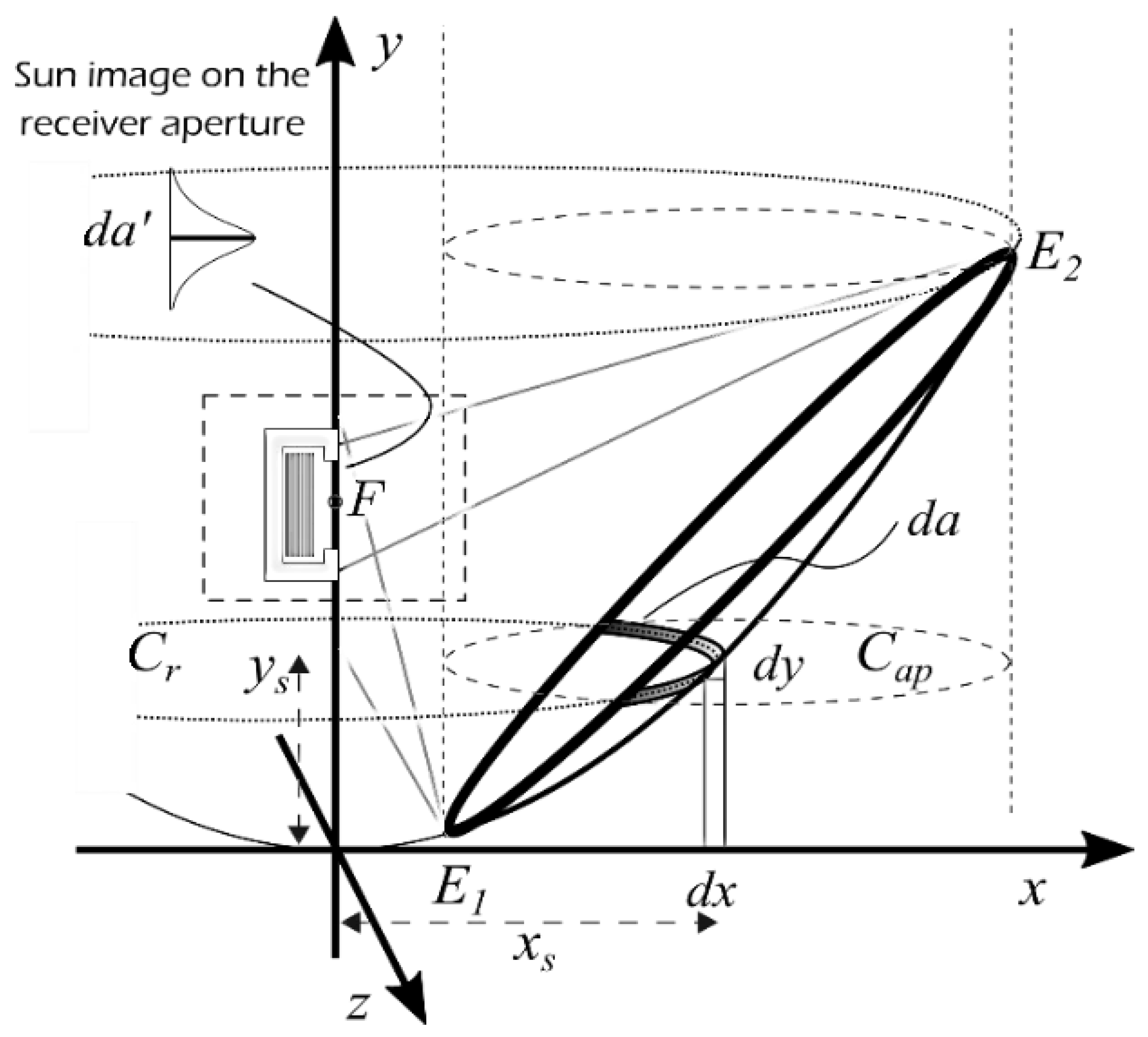
3.1. The Scheffler Reflector and Receiver

In this paragraph, to analyze the heat exchange phase in the reflector and receiver of the SC solar system with the relevant energy losses, a thermodynamic model was investigated and is shown.
First, Figure 1 shows the principal quantities which are useful to establish the reflection of the solar disk on the infinitesimal section centred at point R of the Scheffler concentrator. Then, to define the image of the solar disk reflected on the focal plane y = f , both optical errors and nonparallel solar rays needed to be considered and evaluated [28]. The sun’s rays draw a cone with an angle equal to 2 θ s , where   θ s 0.27° on the Earth’s surface [29]. The reflection on the focal plane perpendicular to the centre line of the reflected beam assumes a breadth r , as reported in Equation (1). As illustrated in Figure 1, p represents the distance from the focal point F to a common point R ( x R ,   y R ) on the surface of the concentrator [30]:
r ( x R ) = 2 p ( x R ) t a n θ s
Moreover, the reflection on the focal plane parallel to the receiver cavity opening can be described as in Equation (2):
w R = r ( x R ) c o s π 2 ψ
Really, the optical failures of the reflector expand the solar image, thus reducing the whole energy performance of the Scheffler solar system [31]; in fact, when a sun’s ray is incident drawing a cone angle equal to 2 θ s it will be mirrored with a cone angle equal to 2 θ e , where θ e is greater than θ s . Clearly, many failures can impact on the spread of the solar beam, hence influencing the collector system performance. To compute the cumulative effect of all imperfections, the standard deviation   ν of all the errors was calculated by a Gaussian approximation, as reported in Equation (3), which includes the following errors [30]:
  • tracking errors owing to sensors, σ s e n s o r ;
  • errors caused by the width of the sun,   σ s u n ;
  • errors caused by the inaccurate inclination of the parabolic mirror that occur during manufacturing process, σ s t r u c t u r e ;
  • imperfections in the mirror alignment of the receiver, σ a l i g n m e n t ;
  • imperfections owing to deviations in mirror reflectivity, σ r e f l ;
  • imperfections owing to tracking guides not completely aligned,   σ d r i v e .
σ t o t = σ s e n s o r 2 + σ s u n 2 + ( 2 σ s t r u c t u r e ) 2 + σ a l i g n m e n t 2 + σ d r i v e 2 + ( 2 σ r e f l ) 2
The real opening of the focal image mirrored at point R is obtained in Equation (4):
Δ r ( x R ) = 2 p ( x R ) tan ν σ t o t 2
Then, reversing Equation (4) and substituting Equations (1) and (2) with w R substituted with the real aperture of the cavity d a p , c a v , the value of the standard deviation ν at point x R can be calculated as in Equation (5):
ν x R = 2 σ t o t t a n 1 d a p , c a v   s i n ( ψ ) 2 p ( x R )
In Equation (5), the normal distance p ( x R ) from the focal point to the reflector is computed as in Equation (6), with y R = x R 2 / 4 f .
p = x R 2 + ( f y R ) 2
After calculating the image of the sun with the calculation procedure above described, in this section, a receiver thermal model is proposed [23,25]. More in detail, as described in Figure 2, first. the cavity receiver absorbs solar power from the reflector by a tube bundle. Successively, see Figure 3, the cavity receiver transmits the remaining thermal power to the operating fluid, considering all the energy losses that exert influence on the heat exchange phase.
Equation (7) and Figure 3 describe the thermal balance in the cavity receiver. Hence, the net heat accessible to transmit to the working fluid, Qnet, is appraised as the difference between the whole thermal energy focused on the cavity, Qrec, and all energy losses, Qloss, that influence the heat transfer process, including radiation, convection and conduction losses.
Q n e t = Q r e c Q l o s s = Q r e c Q r a d , r e f Q r a d , e m i Q c o n v , n a t Q c o n v , f o r Q c o n v , c o n d
Equation (8) evaluates the whole thermal energy gathered in the cavity [28] ,     Q r e c , where I d represents the solar irradiation (W/m2), A a p , r e f (m2) denotes the aperture area of the reflector, ρ (-) denotes the surface reflection coefficient and φ (-) represents the interception factor of the SC collector. Such an interception factor φ can be computed in Equation (9) as the share of the whole thermal power reflected by the collector P r e f l e c t , t o t efficiently transmitted and intercepted by the cavity receiver P i n t e r c e p t , t o t [32]. All other terms of Equation (8) are known [21].
Q r e c = I d A a p , r e f ρ φ
φ = P i n t e r c e p t , t o t P r e f l e c t , t o t = A B I a d a I a d a
Successively, to determine the integral at the numerator of Equation (9), the generic element d A s = d s   x s   d θ of the mirror plane must be defined. d A s is considered (see Figure 2) as the interception of the element d x along the x axis and the element of arc x s   d θ of the circumference C r rotating the paraboloid at the same position, with limits on the elliptical boundary of the mirror (with coordinates ± z b along the z axis), hence depicting the darkened area d a of Figure 2. Then, by replacement of the equation of the parabola and since d s 2 = d x 2 + d y 2 :
d s = 1 + x 2 f 2 d x
Coordinates ± z b as a function of x s can be assessed by overlapping the equation of the circumference C a p of the sun interception area lying on the plane y = y s (which has the centre at point ( x c ,   y s ) and radius r ) and the function of the circumference C r with radius x s :
x x c 2 + z 2 = r 2 x 2 + z 2 = x s 2
whose solutions are:
x b = x c 2 + x s 2 r 2 2 x c ,   z b = ± x s 2 x b 2
Let θ b = a r c s i n ( z b / x s ) , the numerator of Equation (9) can be determined as in the integral of Equation (11), while the integral at denominator of Equation (9) can be assumed as P r e f l e c t , t o t = I d π r 2 .
E 1 E 2 I a d a = x 1 x 2 z b + z b I a d A s = x 1 x 2 θ b + θ b I d cos ψ / 2 1 + x s 2 f 2 x s d θ d x
In the SC concentrators, the maximum error of the polynomial approximation I a is obtained as a continuous function [30]. Then, the normal distribution of the focal point radiation can be obtained as in the formula of Equation (12). which is solved when the rest res is considered negligible [33]. In Equation (12), t = 1 + a   ν ( x s ) / 2 1 , ν ( x s ) depends on the diameter of the opening of the cavity receiver (see Equation (5)), while all other coefficients are reported in Table 1.
I x = I d 1 2 2 π e ν x 2 8 k 1 t + k 2 t 2 + k 3 t 3 + k 4 t 4 + k 5 t 5 + 2 r e s
The interception factor φ of SC collector is assessed by replacing the statistical, geometric and optical results (that depend on the properties and dimensions of the Scheffler concentrator) in Equations (9) and (11), and resolving the integral of Equation (11), hence achieving the formula of Equation (13):
φ = x 1 x 2 θ b θ b I x s cos ψ / 2 1 + x 2 f 2 x s Δ x Δ θ I d ( π r 2 )
Once the thermal power collected in the cavity receiver (Qrec) is estimated by fallowing the previous calculation procedure, the total energy losses, Q l o s s , must be evaluated by determining all the terms indicated in Equation (7).
The energy loss caused by reflected radiations, Q r a d , r e f , is assessed adopting Equation (14), where the expression ( 1 α e f f ) is considered as the reflectance of the cavity calculated as in Equation (15), whereas A a p , c a v and αcav indicate the aperture area and the absorbance factor of the cavity, respectively [28].
Q r a d , r e f = ( 1 α e f f ) Q r e c
α e f f = α c a v α c a v + 1 α c a v A a p , c a v A c a v
Radiation losses, Q r a d , e m i , are caused by emitted radiations, which are computed with Equation (16), where T a m b is the ambient temperature, and T c a v represents the temperature of the cavity.
Q r a d , e m i = ε c a v σ A i n t , c a v ( T c a v 4 T a m b 4 )
In Equation (16), the effective emission factor ε e f f is evaluated the expression of Equation (17) [32], where Lcav denotes the cavity length (as shown in Figure 3) and supposing, by limiting the validity of the analysis to sunny days, ε c a v = α c a v . Also, A i n t , c a v represents the inner surface of the cavity.
ε e f f = 1 ε c a v ε c a v 1 + 4 L c a v 2 R c a v + 1 1
The energetic performance of the cavity receiver depends mainly on the heat exchange, owing to convection process that considers the thermal flow coming out of the opening area of the cavity. Then, two independent convection heat losses are considered in this model that are natural and forced convection thermal losses. The natural convection heat losses, Q c o n v , n a t , are calculated in Equation (18), where h i n t , n a t represents the natural convection heat transfer factor which can be assessed through the Nusselt number.
Q c o n v , n a t = h i n t , n a t A i n t , c a v ( T c a v T a m b )
Following Stine and McDonald [34], the Nusselt’s number depends on both the geometry and temperature of the cavity through the formulas reported in Equation (19) and Equation (20) [30], where θ represents the inclination angle of the cavity, while G r (calculated in Equation (21)) denotes the Grashof number for natural convection inside the cavity. In such last equation, ν c a v and β c a v correspond to the kinematic viscosity and the isobaric compressibility factor of the gas, respectively, while g denotes the gravitational acceleration.
N u i n t , n a t = 0.088 G r 1 3 T c a v T a m b 0.18 c o s ( θ ) 2.47 d a p , c a v d c a v m
m = 0.982 d a p , c a v d c a v + 1.12
G r = g β c a v ( T c a v T a m b ) d c a v 3 ν c a v 2
The forced convection losses in a cavity receiver are evaluated by summing two terms: caused by lateral wind and front wind [35]. The heat exchange factor caused by lateral wind component V s is expressed in Equation (22). The heat transfer factor caused by frontal wind component V f is calculated in Equation (23), with the function f θ assessed in Equation (24). Then, the forced convection losses, Q c o n v , f o r , can be evaluated by summing these two contributions, as expressed in Equation (25):
h f o r c e d , s i d e o n = 0.1967 V s 1.849
h f o r c e d , h e a d o n = f θ V f 1.401
f θ = 0.163 + 0.749 s i n θ 0.502 sin 2 θ + 0.327 s i n ( 3 θ )
Q c o n v , f o r = h f o r c e d , s i d e o n + h f o r c e d , h e a d o n A i n t , c a v ( T c a v T a m b )
Finally, conduction heat losses are transmitted by a convection process via the internal walls of the cavity to the outward ambient (see Equation (26)) [21]. The convection heat transfer factor, h e x t , c a v , includes both natural and forced convection coefficients ( h e x t , n a t and h e x t , f o r ), as reported in Equation (27) [30]. Then, to evaluate these two convection coefficients on the outside surface of the cavity ( A e x t , c a v ) when oriented vertically, the Nusselt numbers are expressed in Equations (28) and (29), in which Pr and Re represent the Prandtl number and the Reynolds number, respectively [36].
Q c o n v , c o n d = ( T c a v T a m b ) L k i n t A i n t , c a v + 1 h e x t , c a v A e x t , c a v
h e x t , c a v = ( h e x t , n a t 3 + h e x t , f o r 3 ) 1 3
N u e x t , n a t = 0.27 R e 1 / 4
N u e x t , f o r = 0.664 R e 1 / 2 P r 1 / 3
Conclusively, for SC receivers, the solar energy collection efficiency ηSOL is assessed (see Equation (30)) by the fraction between the net thermal power Qnet effectively transferred to the operating fluid and the whole sun radiation reaching the reflector Id·Aap,ref, so considering all energy losses which affect the heat exchange phase, as expounded in detail in this section.
η S O L = Q n e t I d · A a p , r e f

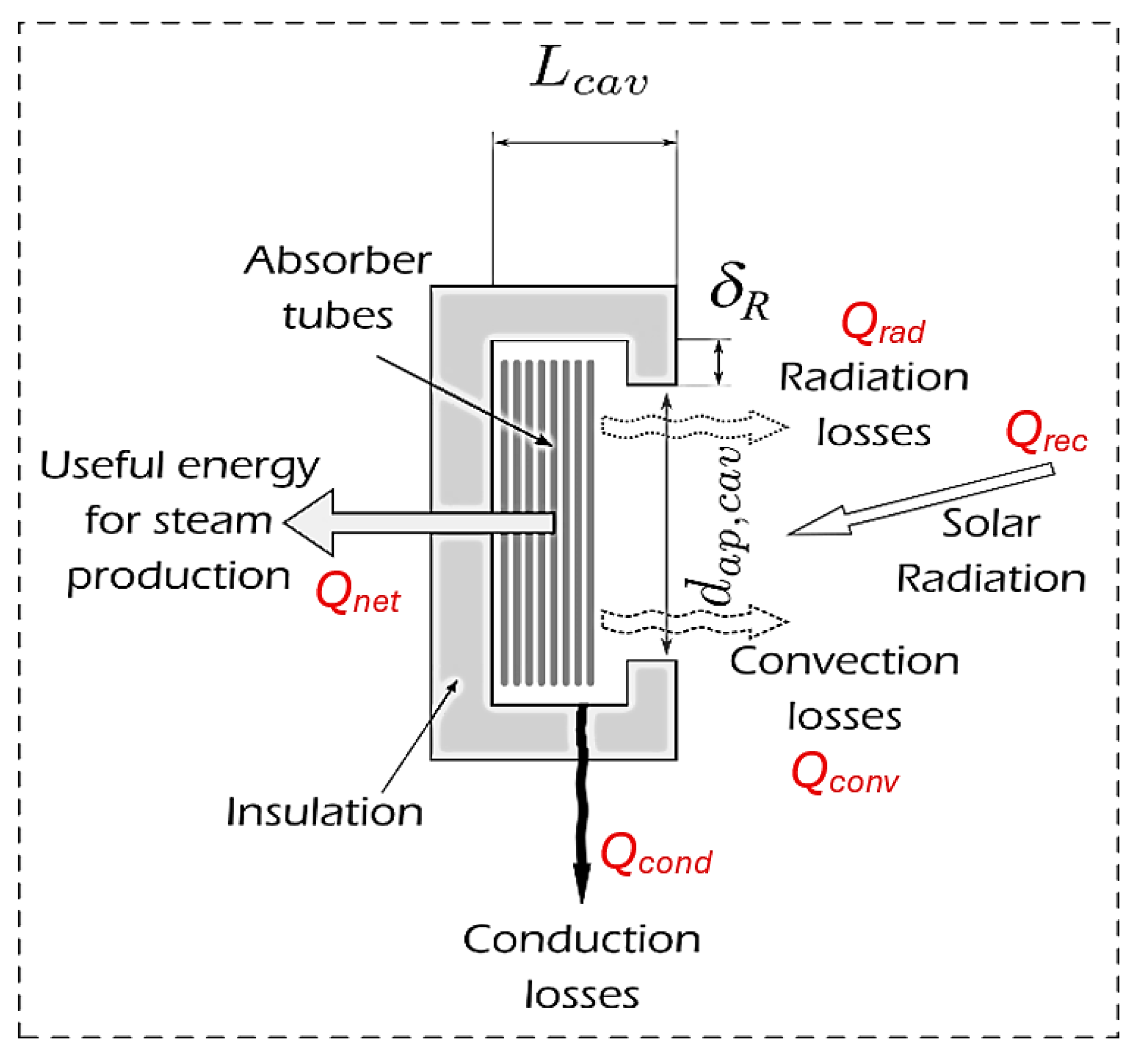
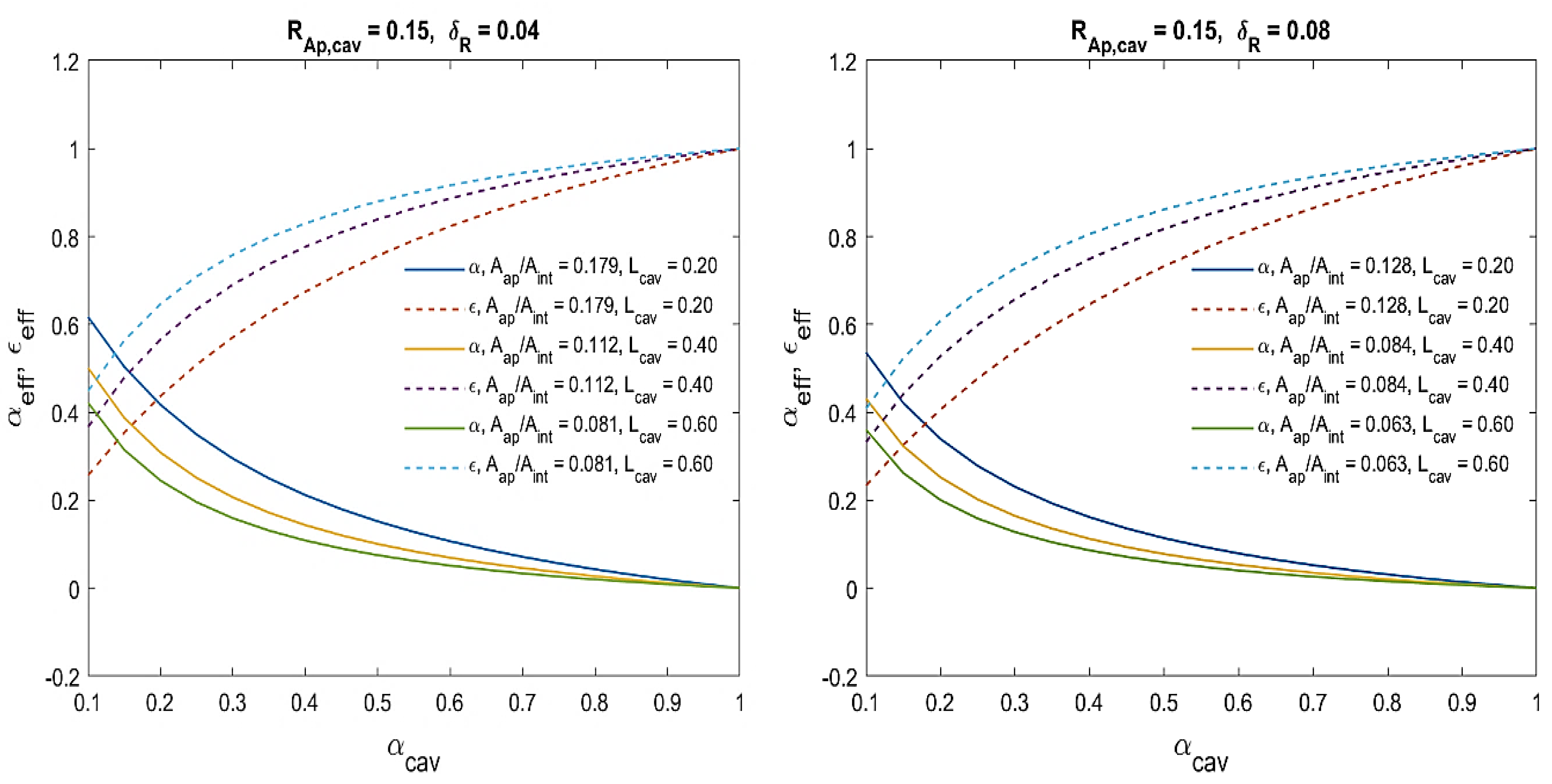
The Selection of Geometric Factors of the Scheffler Receiver System and Model Validation

To illustrate the application of the model previously described and its validation, the effect of the variation of the main geometrical parameters of the cavity is illustrated assuming a Scheffler reflector with a nominal aperture of 27.6 m2, corresponding to the aperture of a parabolic mirror for which experimental data are available [19,37]
The size of the Scheffler receiver must be selected to minimalize the energy losses, mainly in radiative contributions [21]. Hence, starting from the selection of a definite aperture of the cavity ( d a p , c a v = 0.30 m) that guarantees a satisfying interception factor φ = 0.98 , the radiative losses factors α e f f and ε e f f (reported in Equations (15) and (17)) can be plotted against the absorbance factor of cavity α c a v for numerous values of dimension δ R and cavity length L c a v (displayed previously in Figure 3). Hence, Figure 4 shows two plots of α e f f and ε e f f for two different levels of dimension δ R .
From the evaluation of the diagrams reported in Figure 4, when α c a v = 0.56 (as fixed in previous experimental tests on an analogous configuration [19]), the radiative losses coefficients are always significant and decline with decreasing cavity lengths Lcav, with insignificant effects caused by the increased aperture diameter of the cavity d a p , c a v   (for set cavity diameter d a p = d a p , c a v + 2 δ R , see Figure 3). Hence, assuming realistic values of the main physical parameters [21], satisfactory energy performance of the SC reflector cavity receiver could be reached by assuming the geometric factors itemized in Table 2.
The validation procedure of the numerical models proposed for the SC system was verified using the test data obtained in previous experimental research [37].
To conduct the mathematical validation of the geometric–optical model examined in the present investigation, the levels of interception factor φ (computed as in Equation (13)) for the SC solar system were compared with the experimental data attained on an equivalent parabolic dish (Figure 5) [37]. Such a comparison reveals that, with the Scheffler mirror, a higher aperture diameter of the cavity was required to obtain a comparable interception factor in regard to the symmetric parabolic reflector, but with the benefit of moving the receiver away from the moving structure, which made it possible to choose a much cheap and lighter mirror. Anyway, as explained in Figure 5, the optical–geometric model proposed in this study reveals a satisfactory approximation of the test data; in effect, when the aperture diameter was higher than 0.16, differences in the interception factor between the experimental and mathematical results were always <10%.
Subsequently, further experimental data obtained in the same experimental activity on a cavity receiver system [37] were considered to accomplish the validation of the proposed receiver thermal model and then to evaluate its sensitivity with the variation in the geometric parameters. Hence, the intercepted thermal power and principal computed thermal losses achieved from the thermal model of the Scheffler solar system were compared with the experimental results, which are reported in the first column of Table 3.
In this regard, the second column of this table (Model-1) indicates the main results achieved by applying the model for a receiver cavity when the pertinent geometric factors were hypothesized as equal to those established in the mentioned experimental activity [37]. Instead, the third column (Model-2) reports the numerical values of the thermal model achieved for the selected geometric parameters of the receiver system investigated in this analysis, which have been already reported in Table 2, but coupled with the parabolic solar dish used in the experiments reported in [37].

3.2. The PTC Receivers

Nowadays, solar electricity generation systems equipped with PTCs represent a well-recognized technological solution to exploit solar power and are widespread throughout the world. In fact, these CSP plants account for about 90% of the whole capacity of real SEGS. For solar thermal power generation, besides, DSG solar power plants equipped with PTCs represent promising technology for cost savings.
The solar collection efficiency of a single PTC, ηPTC, is assessed in Equation (31), where Ta (K) represents the ambient temperature, Id (W/m2) represents the solar irradiation and T (K) indicates the temperature at the PTC inlet [22].
η P T C T = 0.762 0.2125 · T T a I d 0.00167 · T T a 2 I d
In CSP systems with DSG based on PTCs, to evaluate the global solar power collection efficiency, many elementary collectors are installed, and the average working temperature of adjoining basic modules is assumed to vary uniformly from one elementary collector to another.
However, in (PTC)-based CSP systems, the solar field consists of vapor–liquid blend. In effect, water, which heats up flowing in the PTCs, is both in liquid-phase and binary-phase region; subsequently, at PTC outlet, it becomes dry saturated steam.
In the liquid-phase region, the collector area Al necessary to reach a particular value of outlet temperature Tout starting from a set value of inlet temperature Tin is computed in Equation (32). In this equation, Cp(T), that is assessed in Equation (33) by first-order approximation, represents the thermal capacity of water in the liquid state. In Equation (33), α represents the gradient of the first-order approximation [7], Cp,0 represents the thermal capacity of water in relation to reference temperature T0 (that represents the PTC inlet temperature Tin in this case) and T represents the temperature of water in the liquid state which ranges from Tin to Tout.
A l = T i n T o u t m ˙ · C p T η P T C T · G b d T
C p T = C p , 0 + α T T 0
By developing the analytic solution to the integral function represented in Equation (32), solar energy collection efficiency in liquid state is computed as in Equation (34), where ∆hl indicates the enthalpy raise in the liquid phase region of water, and denotes the mass flow rate of water flowing in the PTCs.
η P T C , l = m ˙ · h l A l · I d
Obviously, the solar collector efficiency in binary-phase region, ηPTC,b, can be assessed as in Equation (31) since water temperature is always constant in this region. Hence, the required collector area in binary phase region, Ab, is estimated as in Equation (35), where ∆hb represents the enthalpy raise in the binary phase region of water.
A b = m ˙ · h b η P T C , b · G b
For SEGSs based on PTCs, the global solar collector efficiency can be calculated as in Equation (36), because the solar field consists of steam-liquid mix. Clearly, in this equation, Q ˙ indicates the total thermal power transferred to the water (both in the liquid-phase region and binary-phase region).
η P T C = Q ˙ I d · A l + A b = h l + h b h l η P T C , l + h b η P T C , b
Obviously, the total solar collector efficiency of the PTCs can also be represented as in Equation (37), where A represents the overall area (that is the sum of single parabolic collectors), and ∆htot represents the global enthalpy increase of water between the PTC inlet and outlet [7].
η P T C T = Q ˙ I d · A = m ˙ · Δ h t o t I d · A

4. Results and Discussion

In this section, as a result of mathematical simulations based on the thermodynamic models analyzed in the previous section, a comparison between Scheffler and PTC solar systems is conducted in relation to energy performance and solar power collector efficiency.
The energetic assessment of the Scheffler-type receiver was conducted for several operating conditions using the receiver thermal model already shown, thus calculating each possible energy loss which could potentially affect the thermal transfer phase in the cavity of the receiver. Then, in this study, such a thermodynamic model was implemented in a numerical code, performing the parametric optimization of the major thermodynamic factors and calculating the solar collection efficiency of the designed solar receiver at part-load operating states.
In depth, at the Scheffler outlet, vaporization temperature of water was assumed to be constantly variable between 170 °C and 300 °C at steps of 10 °C, while sun radiance intensity Id was supposed to range from 300 W/m2 to 1000 W/m2. Afterward, once all thermodynamic factors for mathematical simulations were fixed and by applying the mathematical model presented in the previous section, the SC solar power collector efficiency could be computed versus evaporation temperature under each value of solar power.
Hence, to assess all thermal dispersions and optical losses which affect the receiver and reflector of a Scheffler solar system, SC solar power collector efficiencies were computed and plotted against several values of vaporization temperature of water under various solar radiation intensities (see Figure 6). This solar collection efficiency, ηSOL, indicates the fraction of the total solar radiation reaching the reflector (Id·Aap,ref) that could be effectively transported to the water as net thermal power Qnet (as well explained in Equation (30)). By examining the numerical results of Figure 6, it is obvious that solar collection efficiencies always declined with growing evaporation temperature for each level of solar beam intensity. At the highest solar irradiance intensity (1000 W/m2), in fact, the Scheffler solar collection efficiency decreased from 73.5% to 62.6% with a decreasing vaporization temperature from 300 °C to 170 °C.
Similarly to numerical results shown in Figure 6 for Scheffler-type receivers, the heat collection efficiencies of PTC receivers were estimated versus vaporization temperature and solar irradiance intensity (see Figure 7); these numerical results have been achieved by following the dedicated thermodynamic model (shown in in previous section). By comparing the results of Figure 6 and Figure 7, it seems clear that SC solar receivers turned out well performing in comparison with usual PTCs. This was due to the acceptable efficiency and good compactness of the Scheffler focal receivers which could minimize the heat exchange section with the outward environment [25].
Effectively, as expounded in Figure 6, the solar collector efficiency of Scheffler solar systems appeared sufficiently high even at high values of vaporization temperature. Simultaneously, under high levels of vaporization temperature, the decrease in the solar collector efficiency appeared significant in the PTC solar systems (Figure 7), due to significant radiative and convective heat losses which increased excessively with rising evaporation temperatures [7]. In fact, at the highest value of temperature (which was fixed to 300 °C in our numerical simulations), the SC solar collection efficiency ranged between 24.5% and 62.6% with rising solar power between 300 W/m2 and 1000 W/m2, while the PTC solar collection efficiency ranged between 11.6% and 55.7% in the same solar radiation range.
Moreover, by comparing Figure 6 and Figure 7, the reduction in the thermal collector efficiency with decreasing solar radiance intensity was not very significant for the Scheffler receivers when compared to the PTCs [16]. At the lowest value of solar irradiance intensity Id (which was fixed to 300 W/m2), in fact, the SC solar collection efficiency increased between 24.5% and 60.4% with a decreasing vaporization temperature from 300 °C to 170 °C; for the same vaporization temperature range, the PTC solar collection efficiency increased from 11.6% to 51.2%. Consequently, this last advantage could also mitigate the adverse effect of low solar power on the net energy delivered by DSG power plants based on SC systems compared to equivalent power systems equipped with PTC receivers.
The solar energy collector efficiencies calculated for the PTC and Scheffler solar systems (already shown in the two previous figures) were then compared in the same range of solar radiation intensity and under the same evaporation temperatures. Therefore, from the histogram of Figure 8, it emerges that, for each set evaporation temperature, the highest efficiencies achieved by adopting the Scheffler-type solar receivers at not excessive sun radiance intensity (even lower than 600 W/m2) could achieve the maximum solar power collector efficiencies reached in the PTC systems under the maximum sun radiation (1000 W/m2).
Thus, all these numerical results are very useful to evaluate, in real applications, the energetic advantages of DSG power plants equipped with SC receivers under various thermal power provided by this new type of solar receiver. Really, the results attained in this investigation prove that the Scheffler-type receiver can become a promising technological solution for solar thermal power generation.

5. Conclusions

In this study, basic criteria and a specific thermodynamic model were introduced to appraise the energetic performance of Scheffler solar receivers. For this purpose, the energetic efficiency of the designed solar receiver was evaluated by assessing each possible energy loss influencing the heat exchange phase in the cavity of this solar system. As the main results of the mathematical simulations based on the model proposed for this research, variations in the sun power collection efficiency were appraised with solar irradiation intensities and vaporization temperatures.
The results reached in this study show that the energy performance of Scheffler receivers was higher than that of traditional PTC receivers, under each level of solar power. Moreover, the Scheffler solar collector efficiency proved to be sufficiently high even for high vaporization temperatures, because of low heat losses and effective compactness of the focal receiver. Furthermore, in comparison with conventional PTCs, Scheffler receivers remained less sensitive to changes in solar beam intensity. More in detail, at the lowest value of solar irradiance intensity (300 W/m2), the Scheffler solar collection efficiency increased between 24.5% and 60.4% with decreasing vaporization temperature from 300 °C to 170 °C. At the highest solar irradiance intensity (1000 W/m2), the Scheffler solar collection efficiency rose from 62.6% to 73.5% in the same vaporization temperature range.
For this reason, under variable weather conditions, CSP systems equipped with SC receivers can operate without sensible decrease in energy conversion efficiency when compared to traditional solar power systems which adopt PTCs as thermal sources. Therefore, this research proves that DSG solar power plants equipped with Scheffler-type receivers can allure rising attention in the future as sustainable and profitable solar power systems. In fact, these original renewable energy power systems could be used for civil applications to deliver net power up to 500 kW, then supplying the energy requirements of small urban settlements with reduced size and investments, easy construction and adequate energy conversion efficiency.

Author Contributions

Conceptualization, P.I. and G.L.; methodology, P.I. and F.S.M.; software, P.I. and F.S.M.; validation, P.I., A.A. and G.L.; formal analysis, P.I. and A.A.; investigation, P.I., F.S.M. and A.A.; data curation, P.I. and G.L.; writing—original draft preparation, P.I.; writing—review and editing, P.I. and F.S.M. All authors have read and agreed to the published version of the manuscript.

Funding

This research received no external funding.

Data Availability Statement

No new data was created.

Conflicts of Interest

The authors declare no conflict of interest.

References

  1. Fatigati, F.; Di Bartolomeo, M.; Cipollone, R. Dual intake rotary vane expander technology: Experimental and theoretical assessment. Energy Convers. Manag. 2019, 186, 156–167. [Google Scholar] [CrossRef]
  2. Li, L.; Li, Y.S.; Sun, J. Prospective fully-coupled multi-level analytical methodology for concentrated solar power plants: Applications. Appl. Therm. Eng. 2017, 118, 159–170. [Google Scholar] [CrossRef]
  3. Mcingani, I.; Meyer, E.L.; Overen, O.K. The Impact of Ambient Weather Conditions and Energy Usage Patterns on the Performance of a Domestic Off-Grid Photovoltaic System. Energies 2024, 17, 5013. [Google Scholar] [CrossRef]
  4. Saidi, S.; Abbassi, R.; Ben Hassen, W.; Chebbi, S. Solar photovoltaic energy system-based shunt active filter for electrical energy quality improvement. Int. J. Simul. Process Model. 2016, 11, 119–126. [Google Scholar] [CrossRef]
  5. Abbassi, R.; Saidi, S.; Urooj, S.; Alhasnawi, B.N.; Alawad, M.A.; Premkumar, M. An accurate metaheuristic mountain gazelle optimizer for parameter estimation of single- and double-diode photovoltaic cell models. Mathematics 2023, 11, 4565. [Google Scholar] [CrossRef]
  6. Naseri, A.; Bidi, M.; Ahmadi, M. Thermodynamic and exergy analysis of a hydrogen and permeate water production process by a solar-driven transcritical CO2 power cycle with liquefied natural gas heat sink. Renew. Energy 2017, 113, 1215–1228. [Google Scholar] [CrossRef]
  7. Iodice, P.; Langella, G.; Amoresano, A. Energy performance and numerical optimization of a screw expander–based solar thermal electricity system in a wide range of fluctuating operating conditions. Int. J. Energy Res. 2020, 44, 1858–1874. [Google Scholar] [CrossRef]
  8. Li, L.; Sun, J.; Li, Y. Thermal load and bending analysis of heat collection element of direct-steam-generation parabolic-trough solar power plant. Appl. Therm. Eng. 2017, 127, 1530–1542. [Google Scholar] [CrossRef]
  9. Sachdeva, J.; Singh, O. Comparative evaluation of solarized triple combined cycle for different ORC fluids. Renew. Energy 2021, 163, 1333–1342. [Google Scholar] [CrossRef]
  10. Petrollese, M.; Cocco, D. A multi-scenario approach for a robust design of solar-based ORC systems. Renew. Energy 2020, 161, 1184–1194. [Google Scholar] [CrossRef]
  11. Roumpedakis, T.C.; Loumpardis, G.; Monokrousou, E.; Braimakis, K.; Charalampidis, A.; Karellas, S. Exergetic and economic analysis of a solar driven small scale ORC. Renew. Energy 2020, 157, 1008–1024. [Google Scholar] [CrossRef]
  12. Li, L.; Sun, J.; Li, Y.; He, Y.L.; Xu, H. Transient characteristics of a parabolic trough direct-steam-generation process. Renew. Energy 2019, 135, 800–810. [Google Scholar] [CrossRef]
  13. Price, H.; Lu¨ pfert, E.; Kearney, D.; Zarza, E.; Cohen, G.; Gee, R.; Mahoney, R. Advances in parabolic trough solar power technology. J. Sol. Energy Eng. 2002, 124, 109–125. [Google Scholar] [CrossRef]
  14. Li, L.; Sun, J.; Li, Y.S. Prospective fully-coupled multi-level analytical methodology for concentrated solar power plants: General modelling. Appl. Therm. Eng. 2017, 118, 171–187. [Google Scholar] [CrossRef]
  15. Laing, D.; Bahl, C.; Bauer, T.; Lehmann, D.; Steinmann, W.D. Thermal energy storage for direct steam generation. Sol. Energy 2011, 85, 627–633. [Google Scholar] [CrossRef]
  16. Iodice, P.; Langella, G.; Amoresano, A. Exergetic analysis of a new direct steam generation solar plant using screw expanders. Energies 2020, 13, 720. [Google Scholar] [CrossRef]
  17. Li, J.; Li, P.; Gao, G.; Pei, G.; Su, Y.; Ji, J. Thermodynamic and economic investigation of a screw expander-based direct steam generation solar cascade Rankine cycle system using water as thermal storage fluid. Appl. Energy 2017, 195, 137–151. [Google Scholar] [CrossRef]
  18. Iodice, P.; Amoresano, A.; Langella, G.; Marra, F.S. Comprehensive assessment and energetic-exergetic performance optimization of a new solar thermal electricity system based on Scheffler-type receivers combined with screw-type volumetric machines. Int. J. ThermoFluids 2024, 24, 100881. [Google Scholar] [CrossRef]
  19. Ruelas, J.; Velázquez, N.; Cerezo, J. A mathematical model to develop a Scheffler-type solar concentrator coupled with a Stirling engine. Appl. Energy 2013, 101, 253–260. [Google Scholar] [CrossRef]
  20. Munir, A.; Hensel, O.; Scheffler, W. Design principle and calculations of a Scheffler fixed focus concentrator for medium temperature applications. Sol. Energy 2010, 84, 1490–1502. [Google Scholar] [CrossRef]
  21. Iodice, P.; Amoresano, A.; Langella, G.; Marra, F.S. Combined use of volumetric expanders and Scheffler receivers to improve the efficiency of a novel direct steam solar power plant. Int. J. Energy Res. 2021, 45, 21058–21081. [Google Scholar] [CrossRef]
  22. Li, J.; Li, P.; Pei, G.; Alvi, J.Z.; Ji, J. Analysis of a novel solar electricity generation system using cascade Rankine cycle and steam screw expander. Appl. Energy 2016, 165, 627–638. [Google Scholar] [CrossRef]
  23. Fraser, P.R. Stirling Dish System Performance Prediction Model. Master’s Thesis, University of Wisconsin-Madison, Madison, WI, USA, 2008. [Google Scholar]
  24. Stefanovic, V.P.; Pavlovic, S.R.; Bellos, E.; Tzivanidis, C.A. detailed parametric analysis of a solar dish collector. Sustain. Energy Technol. Assess. 2018, 25, 99–110. [Google Scholar] [CrossRef]
  25. Shubham; Kumar, P.; Kumar, S.; Kumar, R.; Mandal, S. Numerical and experimental analysis of Scheffler concentrator receiver for steam generation using phase change material. Int. J. Renew. Energy Res. 2018, 8, 1339–1345. [Google Scholar]
  26. Chandak, A.; Somani, S.-K.; Dubey, D. Design, development of and testing of multieffect distiller/evaporator using Scheffler solar concentrator. J. Eng. Sci. Technol. 2009, 4, 315–321. [Google Scholar]
  27. Ramachandran, S.; Nene, A.A. Studies on Scheffler solar concentrator to optimise thermal efficiency. Int. J. Ambient. Energy 2020, 43, 3138–3145. [Google Scholar] [CrossRef]
  28. Duffie, J.A.; Beckman, W.A.; Worek, W.M. Solar Engineering of Thermal Processes; Wiley: New York, NY, USA, 2013. [Google Scholar]
  29. Dib, E.A.; Fiorelli, F.A. Analysis of the image produced by Scheffler paraboloidal concentrator. In Proceedings of the 5th International Youth Conference on Energy (IYCE), Pisa, Italy, 27–30 May 2015; pp. 1–7. [Google Scholar]
  30. Stine, W.B.; Harrigan, R.W. Solar Energy Fundamentals and Design with Computer Applications; WileyInterscience: New York, NY, USA, 1985. [Google Scholar]
  31. Shuai, Y.; Xia, X.L.; Tan, H.P. Radiation performance of dish solar concentrator/cavity receiver systems. Sol. Energy 2008, 82, 13–21. [Google Scholar] [CrossRef]
  32. Azzouzi, D.; Boumeddane, B.; Abene, A. Experimental and analytical thermal analysis of cylindrical cavity receiver for solar dish. Renew. Energy 2017, 106, 111–121. [Google Scholar] [CrossRef]
  33. Bramowitz, M.; Stegun, I.A. Handbook of Mathematical Functions: With Formulas, Graphs, and Mathematical Tables, National Bureau of Standards Applied Mathematics Series 55; Tenth Printing; U.S. Government Printing Office: Washington, DC, USA, 1972.
  34. Stine, W.B.; McDonald, C.G. Cavity Receiver Convective Heat Loss; International Solar Energy Society. In Proceedings of the 1989 Congress of the ISES, Kobe, Japan, 4–8 September 1989. [Google Scholar]
  35. Harris, J.A.; Lenz, T.G. Thermal performance of solar concentrator/cavity receiver systems. Sol. Energy 1984, 34, 135–142. [Google Scholar] [CrossRef]
  36. Incropera, F.P.; DeWitt, D.P.; Bergman, T.L.; Lavine, A.S. Fundamentals of Heat and Mass Transfer; John Wiley & Sons. Inc.: Hoboken, NJ, USA, 2002. [Google Scholar]
  37. Reinalter, W.; Ulmer, S.; Heller, P.; Rauch, T.; Gineste, J.; Ferriere, A.; Nepveu, F. Detailled performance analysis of the 10 kW CNRS-PROMES dish/Stirling system. In Proceedings of the 13th SolarPACES International Symposium, Seville, Spain, 20–23 June 2006; pp. 1–9. [Google Scholar]
Figure 1. On the left, the reflection of a solar ray cone in the focal section is shown, also considering imperfections. On the right, the aggrandizement of the focal plane is shown with the sign of the solar image in evidence.
Energies 17 05393 g001
Figure 2. The entire layout of the combination of receiver and reflector.
Energies 17 05393 g002
Figure 3. The extended design and thermal balance of the Scheffler cavity receiver.
Energies 17 05393 g003
Figure 4. Main factors of the radiative losses calculated versus the geometric characteristics of the cavity receiver.
Energies 17 05393 g004
Figure 5. Interception factor against aperture diameter of the cavity: comparison between the numerical results of the SC system and test data [37] attained for an equivalent parabolic dish.
Energies 17 05393 g005
Figure 6. SC solar power collector efficiency computed versus solar power intensity and evaporation temperature.
Energies 17 05393 g006
Figure 7. PTC solar power collector efficiency computed versus solar power intensity and evaporation temperature.
Energies 17 05393 g007
Figure 8. Solar power collector efficiency computed versus solar power intensity and evaporation temperature: comparison between PTC and Scheffler solar systems.
Energies 17 05393 g008
Table 1. Elements of the polynomial distribution approximation.
ak1k2k3k4k5
0.2316420.31938153−0.356563781.78147794−1.82125981.33027443
Table 2. Fixed geometric and physical factors for assessment of the solar power collector efficiency of the SC solar system.
Geometric FactorsValueUnitPhysical CharacteristicsValueUnit
Absorber tubes diameter0.0063mAir conductivity0.028W/mK
Cavity   aperture   diameter   d a p , c a v 0.3mAmbient temperature293K
Capture area A a p , r e f 27.6m2Cavity absorbance   α c a v 0.56-
Cavity diameter d a p 0.46mInsulation conductivity k i n s 0.08W/mK
Cavity length L c a v 0.46mLatitude41deg
Cavity wall thickness0.05mMirror reflectance ρ 0.9-
Focal length f 2.1mOptical errors deviation ν 0.011rad
N. of absorber tubes71-Wind velocity3m/s
Table 3. Compare between the numerical results and the experimental data [37].
PD Experimental Results [kW] [37]Model-1 [kW]Model-2 [kW]
Captured sun radiation48.0248.0248.02
Intercepted heat power37.7535.3043.64
Heat loss owing to convection1.980.580.40
Heat loss due to reflected radiation1.7118.173.53
Heat loss due to emitted radiation 2.390.495.77
Net thermal power31.6716.0533.66
Disclaimer/Publisher’s Note: The statements, opinions and data contained in all publications are solely those of the individual author(s) and contributor(s) and not of MDPI and/or the editor(s). MDPI and/or the editor(s) disclaim responsibility for any injury to people or property resulting from any ideas, methods, instructions or products referred to in the content.

