Article

High-Energy-Density Lithium–Sulfur Battery Based on a Lithium Polysulfide Catholyte and Carbon Nanofiber Cathode

1
School of Advanced Materials Engineering, Jeonbuk National University, Jeonju 54896, Republic of Korea
2
Energy 11 Co., Ltd., 224 Bongdong-eup, Wanjusandan 6-ro, Wanju-gun 55315, Republic of Korea
3
Department of Integrative Environmental Biotechnology, College of Environmental and Bioresource Sciences, Jeonbuk National University, Iksan 54596, Republic of Korea
*
Authors to whom correspondence should be addressed.
These authors contributed equally to this work.
Energies 2024, 17(21), 5258; https://doi.org/10.3390/en17215258
Submission received: 21 September 2024 / Revised: 15 October 2024 / Accepted: 21 October 2024 / Published: 22 October 2024
(This article belongs to the Special Issue Advances in Secondary Battery)

Abstract

:
Li–S batteries are promising large-scale energy storage systems but currently suffer from performance issues; a major reason is the dissolution of polysulfides in electrolytes. To this end, we report a high-energy-density Lithium–Sulfur (Li–S) battery that combines a catholyte and a sulfur-free carbon nanofiber (CNF) cathode. The cathode was synthesized by carbonizing binder-free polyacrylonitrile (PAN) nanofibers, affording a high surface area. In the catholyte, added polysulfides acted as both conductive Li salts and active materials. Investigating the electrochemical performance of this concept in both Swagelok- and pouch-type cells afforded energy densities exceeding 3 mAh cm−2 at a discharge rate of 0.1 C. This combination could also be utilized in high-capacity pouch cells with capacities of up to 250 mAh g−1. Both cell types exhibited good cycle performance. Adding LiNO3 to the electrolyte suppressed the redox shuttle reactions. Moreover, the cathode being binder-free increased the energy density and simplified cathode fabrication. Characterizing the cathode before and after cycling revealed that deposition was reversible, and that cell reactions at least partially formed sulfur as the end product, resulting in high sulfur amounts in the cell. We expect our concept to greatly aid in the development of practically applicable Li–S cells.

1. Introduction

Though there have been significant strides in small-scale Li-battery technology for portable devices [1], the demand for large-scale energy storage systems has surged in recent years, driven by the need for renewable energy and electromobility. These applications require batteries with high capacities and long cycle lives, such as to provide electric vehicles with sufficient driving distance on a single charge. In this context, Lithium–Sulfur (Li–S) batteries exhibit immense promise owing to their high theoretical energy densities (1675 mAh g−1, 2500 Wh kg−1) that surpass those of current Li-ion batteries by 5–10 times (LiCoO2, = 274 mAh g−1, LiFePO4 = 170 mAh g−1, and LiNi1/3Co1/3Mn1/3O2 = 278 mAh g−1) [2,3,4,5,6]. Our research aims to contribute to this field by presenting a high-energy-density Li–S battery concept that could revolutionize energy storage and electromobility.
The basic concept behind Li–S batteries has been known for some time; however, several performance issues—high self-discharge, low cycle life, and low charge/discharge efficiency—have hindered the realization of this technology in practice. The high capacities of Li–S batteries stem from the electrochemical conversion of pure S in the charged state to Li2S in the discharged state. This transition occurs in a series of steps involving the formation of polysulfides (Li2Sx, x = 1–8), of which those with higher molecular weights are highly soluble in commonly used electrolytes. The dissolution of the polysulfides in the electrolyte leads to the loss of active material and the occurrence of the shuttle phenomenon, resulting in capacity loss and unwanted side reactions that limit cyclability [7,8,9]. In addition, S has a low electrical conductivity (5 × 10⁻³⁰ S cm−1 at 25 °C); this causes an additional conducting phase to be required for the cathode, which further decreases the practical energy of the Li–S cell [10,11].
Several strategies have been applied to address the problems of low cyclability and low practical energy density based on the development of new material concepts. For instance, S can be confined in carbon and polymer composites, such as in a nanoporous carbon matrix or conducting polymer coating, to prevent the dissolution of polysulfides and improve conductivity. This strategy has improved active material utilization, cycle life, and charge/discharge efficiency [12,13,14,15,16]. However, in general, the S loading is relatively low in these systems, and the process for producing porous carbon is slow; furthermore, there is an additional risk of sulfur loss at the high process temperatures used. Thus, there are limitations on the practical energy density that can be obtained when using this approach.
Recently, progress has been made by combining the S–C composite material approach with another approach of adding Li polysulfides to the electrolyte, known as the catholyte concept. Li–S cells based on the catholyte concept have exhibited improved cycle performances, which is attributed to the buffering effect of the catholyte preventing the dissolution of the cathode [17,18,19,20,21]. Furthermore, the added polysulfides also play a role in modifying the interphase formed on the anode, which improves the stability of the cell, and they are electrochemically active to some extent, which contributes to the cell capacity [20]. However, the overall energy densities of the cells are not improved because the addition of polysulfides increases the additional mass, and because the cathode is still a C–S composite that contains a binder and, in some cases, additional carbon black for improved conductivity.
Herein, we report a novel strategy for applying the catholyte concept to high-energy-density Li–S cells by using a S-free electrospun carbon nanofiber (CNF) cathode. In our catholyte, the added polysulfides acted as both the active material and conducting salt, as our electrolyte comprised only Li2S8 in an organic solvent (tetraethylene glycol dimethyl ether (TEGDME) and 1,3-dioxolane (DIOX), 3:7 w/w). Owing to the chosen solvent, many polysulfides could be dissolved, and the amount of S in the full cell was higher than that in typical S–C composite cathodes. Using CNFs as the cathode provided the advantages of a large surface area and binder-free system, which are also easy to prepare in larger formats [22]. We tested the performances of the catholyte/CNF Li–S cells and characterized the CNF cathode before and after cycling to reveal its role in the functionality of the cell using cyclic voltammetry (CV), field-emission scanning electron microscopy (FE-SEM), and X-ray diffraction (XRD).

2. Materials and Methods

The CNFs for the cathode were prepared by carbonizing electrospun polyacrylonitrile (PAN) nanofibers. To prepare the PAN nanofibers, a solution of 12 wt% PAN (Mw 150,000, Aldrich, St. Louis, MO, USA) in N,N-dimethylformamide (DMF) (Aldrich) was fed into a syringe pump (KD Scientific, Holliston, MA, USA, Model 210) at a constant flux of 0.1 mL min−1 and, under an applied voltage of 20 kV, electrospun into nanofibers, which were collected on aluminum foil fixed on a grounded stainless-steel rotating drum. The PAN nanofibers were then annealed at 300 °C for 1 h in air, following which they were carbonized by heating from room temperature to 1000 °C (10 °C min−1), then held at 1000 °C for 1 h under nitrogen flow (99.99%, 800 mL min−1) [23,24].
Cathodes were prepared by first cutting the CNFs into disks with diameters of 10 mm for Swagelok cells (surface area = 0.7854 cm2) and rectangles with dimensions of 25 × 50 mm for bi-cell-type pouch cells (two cathodes, surface area = 12.5 cm2), followed by vacuum drying at 70 °C for 12 h. Li metal (thickness = 300 µm; Cyprus Foote Mineral Co., Williamsburg, VA, USA) was used as the anode. The reference carbon cathodes were prepared by preparing slurries of conductive carbon (Super-P or CNT) and PVdF at weight ratios of 3:1 in N-methyl pyrrolidone (NMP) (Aldrich) and casting on aluminum foil.
The catholyte, 0.5 m Li2S8 in TEDGME (Aldrich)/DIOX (Aldrich) (3:7 w/w), was prepared by mixing Li2S (Aldrich) and S (Aldrich) in appropriate amounts in TEGDME, followed by the addition of DIOX. To investigate the possibility of preventing redox shuttle reactions caused by the polysulfides, 0.1 m LiNO3 (Aldrich) was added to the catholyte; see further details below. The total amount of sulfur loading in catholyte is 3.82 mg/cm2.
The cells were prepared by stacking the CNF cathode, separator (Celgard 2400 separator, Charlotte, NC, USA), and Li-metal anode in either Swagelok or pouch cells. All material preparations and cell assemblies were performed in an inert atmosphere (H2O and O2 levels < 10 ppm).
The morphology of the CNF cathode was investigated using FE-SEM (JEOL JSM 5600, Tokyo, Japan) at an accelerating potential of 15 kV. XRD (Bruker D8 Advance) was used to investigate the presence of reaction products on the CNF cathodes exposed to the electrolyte after charge/discharge cycling; the XRD experiments were performed at room temperature in a closed system using an A100-B37 holder (Bruker, Billerica, MA, USA) to avoid exposure to air.
CV was performed at a constant sweep rate of 0.1 mV s−1 over the voltage range of 1.5–2.8 V using an automatic galvanostatic charge–discharge WBCS3000 battery cycler (WonA Tech. Co., Seoul, Republic of Korea). Current densities of 127, 245, 635, and 2540 μA/cm2 were used for Swagelok cells (corresponding to the rates 0.02, 0.04, 0.1, and 0.4 C, respectively), and 628 μA/cm2 (0.1 C) was used for the pouch cells. All the cycling experiments were performed at room temperature.

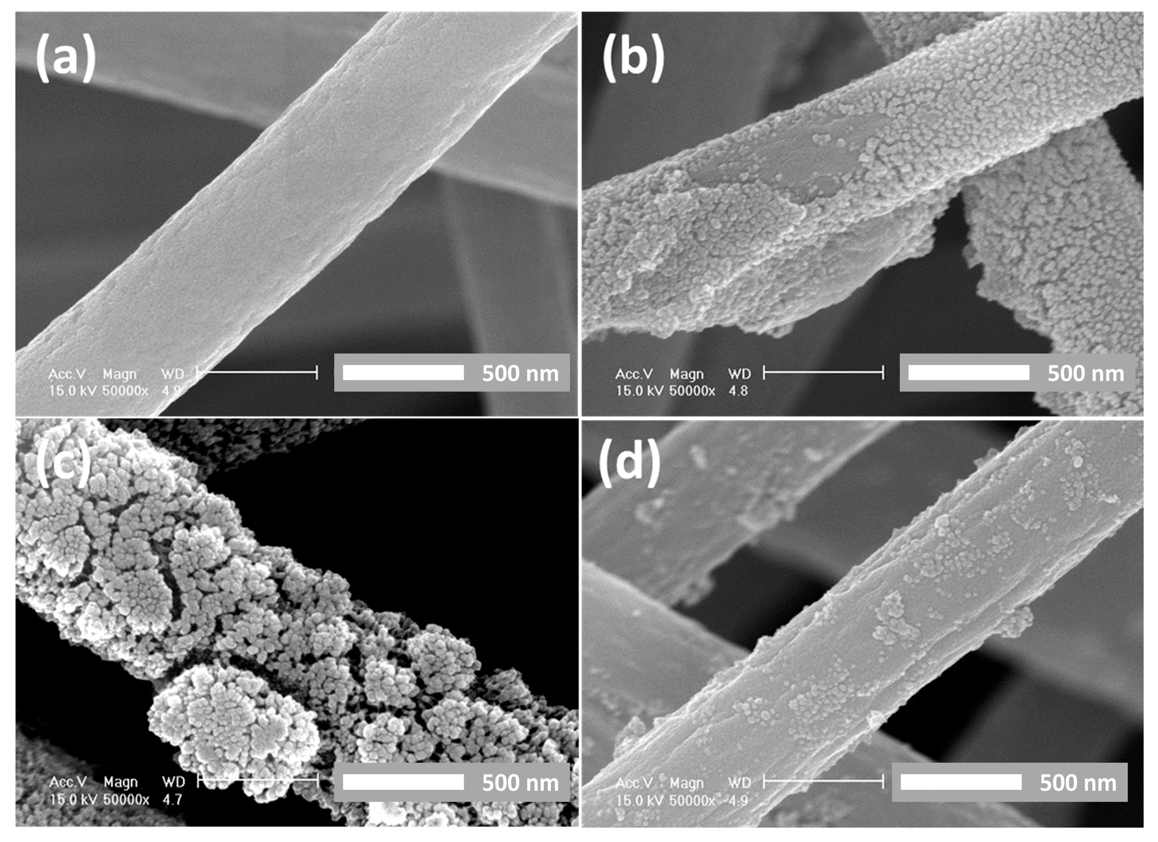
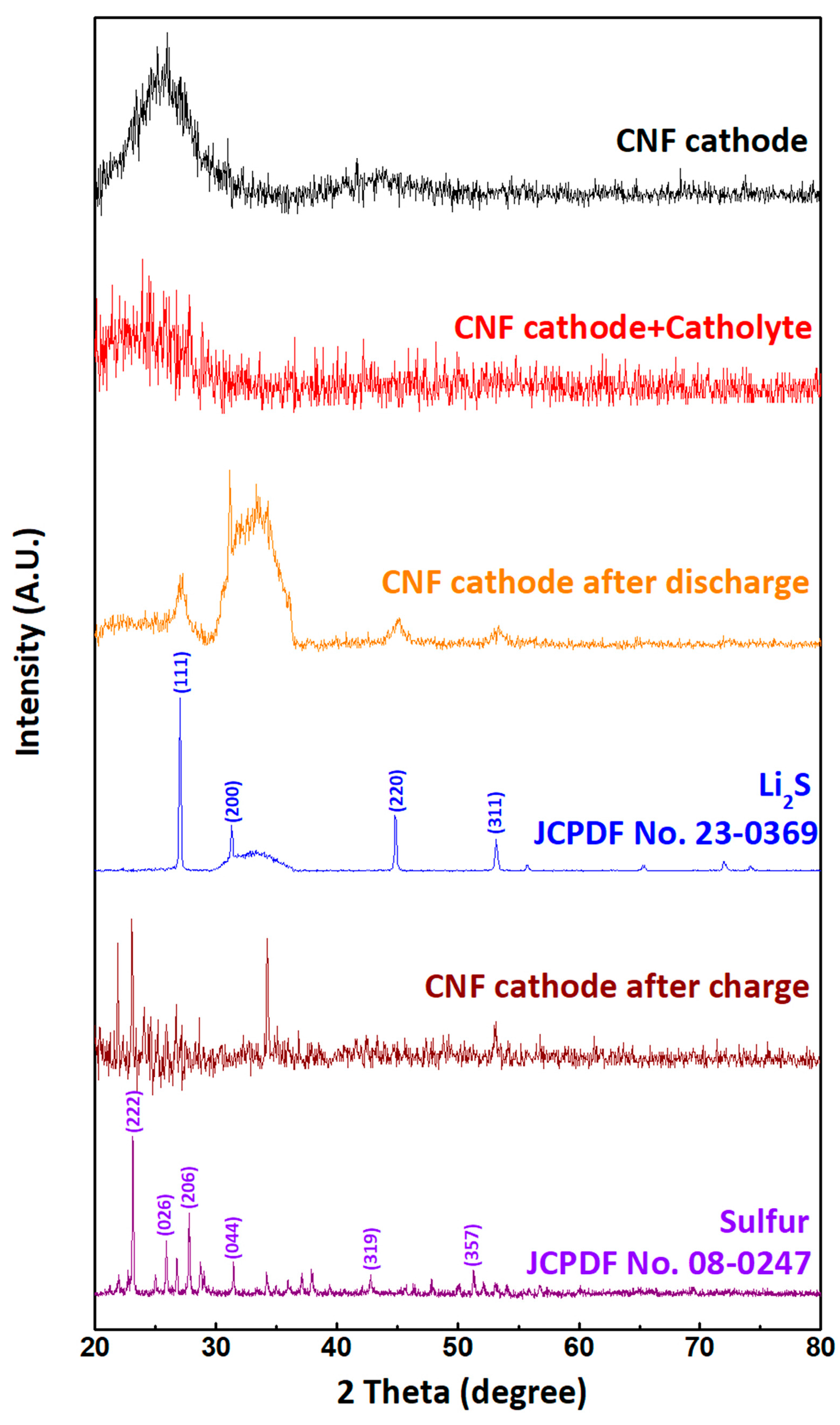
3. Results and Discussion

Figure 1 shows the morphologies of the PAN nanofibers after carbonization. The standard process for converting polymeric PAN nanofibers into CNFs involves oxidative stabilization in an air atmosphere and subsequent carbonization. Oxidative stabilization is essential for increasing the carbon yield and preventing the formation of hollow-core fibers during the subsequent carbonization step. Then, carbonization at high temperatures eliminates unnecessary impurities. As shown in Figure 1a, fabrication via electrospinning resulted in well-constructed nanofiber structures. Figure 1b shows that the nanofiber structure was preserved well upon carbonization, while the nanofiber surface became smoother.
Figure 2a shows the discharge/charge behavior of the Li/catholyte/CNF cell. The first discharge curves of these cells with S-free cathodes showed only one plateau because there was no elemental S in the cells before discharge [25]. The cycling performance of the CNF/catholyte cell was stable, with an energy density of approximately 2.5 mAh/cm2.
To investigate the effects of different carbon materials on cell performance, we compared the performance of the CNF-based cell with those of two other sulfur-free cathodes based on carbon nanotubes (CNTs) and Super-P. The profiles of the discharge curves were highly similar for the three materials, but the cells with the CNT- and Super-P-based cathodes delivered much lower capacities. Notably, the charge cycles of all three cells ended with very flat plateaus, which was attributed to the presence of a pronounced redox shuttle process. This was expected because the active material in each cell completely dissolved in the electrolyte, resulting in complete conversion to sulfur during charging, which is most likely not achieved. This can also be inferred from the discharge behavior, as there was little to no sign of the first plateau at around 2.4 V during discharge.
A common method for addressing redox shuttle reactions in Li–S cells is to add a small amount of LiNO3 to the electrolyte to form a passivating layer on the Li metal anode [26,27]. The mechanism of the action of LiNO3 and the effect of various concentrations of LiNO3 were previously studied [28,29]. Figure 3 shows the CV results and cycling behavior of the Li/(catholyte + LiNO3)/CNF cell at different current densities (discharge/charge rates). In the first cycle of the CV experiment, only one reduction peak at 2.0 V was observed, which is expected because the catholyte cell started discharging from Li2S8 [26]. Two separate reduction peaks were observed at 2.3 and 2.0 V in the subsequent cycles. This is clear evidence that, during the first charge cycle, the reaction proceeded all the way to S and that the redox shuttle reactions were efficiently suppressed.
Suppression of the redox shuttle and the resulting conversion to elemental S resulted in a higher discharge capacity. Figure 4b shows the discharge/charge behavior of Li/(catholyte + LiNO3)/CNF cells. Although the rates were considerably higher (245 and 635 µA cm−2 for discharge and charge, respectively, compared to 127 µA cm−2 in Figure 3), a higher energy density of 3.1 mAh cm−2 was observed, and a relatively stable capacity profile was obtained, with 84% of the capacity being retained after 30 cycles. At a higher current density (2540 µA cm−2 or 0.4 C), the cell exhibited an initial energy density of 1.8 mAh cm−2 and retained 60% of the capacity after 100 cycles. This excellent performance was also preserved when employing a high-energy-density pouch cell. Figure 4 shows the cycling behavior of a Li/(catholyte + LiNO3)/CNF pouch cell; it delivered a discharge capacity of 230 mAh in the second cycle when the full potential was utilized after conversion to S during the first charge, and the electrode retained 80% of its capacity after 10 cycles.
The reported energy density, more than 3 mAh/cm2, is an excellent performance compared with other results reported in the literature, which are typically in the range of 1–1.9 mAh cm−2 [19,30,31]. However, a recent study reported a similar concept to the one presented here; the study reported a very high energy density of 2.9 mAh cm−2, but a very low actual S utilization of approximately 650 mAh g−1 [32]. This shows that to obtain a high-energy density cell, high S utilization, which is typically used as a benchmark of performance in the literature, is not sufficient. Therefore, the excellent performance of the CNF cathode can be directly attributed to the fact that it consists entirely of conducting material without a binder.
To understand the functionality of the CNF cathode and the mechanisms involved in the catholyte cell, we characterized the morphology of the fiber network before and after cycling. Figure 5a shows the SEM image of the as-prepared CNF cathode. The network comprised bead-free fibers with an average diameter of 450 nm. It can be seen in Figure 5b that after exposure to the catholyte (0.5 m Li2S8 in TEGDME/DIOX + 0.1 m LiNO3) but before discharge, the material was deposited on the surfaces of the fibers, but their shapes and dimensions were not altered. After discharge, as shown in Figure 5c, the amount of deposited material was significantly higher, with the deposit almost completely covering the fibers. However, after the subsequent charge cycle, very few deposits remained (Figure 5d). This shows that the fiber network played an active role during charge/discharge cycling and that the deposition process was reversible and did not degrade the CNF.
Further insight into the mechanism was obtained by analyzing the nature of the deposits through XRD experiments. Figure 6 shows the XRD patterns of the as-prepared CNF, CNF exposed to the catholyte, and cathode after discharging and charging. The XRD patterns of Li2S and S are also shown for comparison. No sharp peaks appeared in the XRD pattern of the as-prepared CNF material; rather, broad features characteristic of a material with low crystallinity or a fully amorphous material were observed. Similarly, no sharp peaks were observed for the CNF exposed to the catholyte, indicating that the deposit on the CNF surface was amorphous; however, the XRD pattern after exposure to the catholyte must be considered, as the residues of the electrolyte most likely contributed because the experiments were performed without drying the cathodes. In contrast, the XRD patterns of the cathode after charging and discharging showed sharp peaks, indicating the presence of a crystalline material on the CNF surface. The XRD pattern for the cathode after discharging was identified against the pattern for Li2S, which is the expected end-product; the peaks were rather broad, indicating the presence of a disordered structure or a small-sized crystallite of Li2S on the CNF surface. Meanwhile, after charging, the expected end product is S if the reaction is fully reversible. In the XRD pattern of the CNF cathode after charging, peaks corresponding to S were observed; however, the overall pattern was not a full match. This shows that the reaction in the cell was at least partially successful in reaching S, despite starting with Li2S8 in the initial cycle [30,31].
From the results, it is clear that this catholyte concept, wherein lithium polysulfides act as both the conducting salt and active material, can be used for high-energy-density Li–S batteries. The key to this mechanism is the combination of the high surface area of the CNF cathode and the absence of non-conducting components in the cathode. The cathode structure and morphology were observed by comparing the different carbon structures (CNT and Super-P). Another aspect of the concept presented herein is that it is more environmentally friendly than traditional electrolyte concepts; because we do not use salts other than Li2S8 or LiNO3 in our Li–S cell, it is fluorine-free, unlike standard concepts based on fluorinated salts such as LiTFSI or LiCFSO3. This also decreases the sensitivity to degradation as the hydrolysis of fluorine salts, which creates HF, does not occur.

4. Conclusions

We demonstrated a novel Li–S cell concept based on a Li-salt-free catholyte and self-standing CNF cathode. The fabricated cells exhibited good performances in terms of capacity and cyclability. We then showed that the addition of LiNO3 to the electrolyte efficiently suppressed the redox shuttle mechanism, even in this system in which all active materials are dissolved. The CNF cathode is a critical component of this concept because it has a large surface area and an open structure. The role of the cathode surface was revealed by identifying that the end products Li2S and S were obtained after discharging and charging, respectively. The CNF cathode has the advantage of being binder-free, which increases the practical energy densities of the cells. Furthermore, the absence of a binder considerably simplified the cathode preparation process, which provides excellent potential for upscaling.
Although the concept presented here exhibited excellent performance, there is room for further improvement: the CNF cathode surface and the network morphology can be optimized, and the catholyte can be further optimized to improve the reversibility of the system.

Author Contributions

Methodology and visualization, B.Y.; investigation, S.A.; data curation, J.J.; writing—original draft preparation, B.O.; project administration, D.L.; funding acquisition, I.S. All authors have read and agreed to the published version of the manuscript.

Funding

This work was supported by the Technology Innovation Program (RS-2024-00409601 and RS-2024-00419781), funded by the Ministry of Trade, Industry and Energy (MOTIE, Korea) and Regional Innovation Strategy (RIS) (2023RIS-008) through the National Research Foundation of Korea (NRF), funded by the Ministry of Education (MOE).

Data Availability Statement

The data presented in this study are available on request from the corresponding author. The data are not publicly available as they are part of the ongoing project.

Conflicts of Interest

Authors Byeonghun Oh, Suhyeon Ahn and Duhyun Lim were employed by the company Energy 11 Co., Ltd. The remaining authors declare that the research was conducted in the absence of any commercial or financial relationships that could be construed as a potential conflict of interest.

References

  1. Armand, M.; Tarascon, J.-M. Building better batteries. Nature 2008, 451, 652–657. [Google Scholar] [CrossRef] [PubMed]
  2. Bruce, P.G.; Freunberger, S.A.; Hardwick, L.J.; Tarascon, J.-M. Li–O2 and Li–S batteries with high energy storage. Nat. Mater. 2012, 11, 19–29. [Google Scholar] [CrossRef] [PubMed]
  3. He, P.; Wang, H.; Qi, L.; Osaka, T. Electrochemical characteristics of layered LiNi1/3Co1/3Mn1/3O2 and with different synthesis conditions. J. Power Sources 2006, 160, 627–632. [Google Scholar] [CrossRef]
  4. Gaberscek, M.; Dominko, R.; Jamnik, J. Is small particle size more important than carbon coating? An example study on LiFePO4 cathodes. Electrochem. Commun. 2007, 9, 2778–2783. [Google Scholar] [CrossRef]
  5. Villevieille, C.; Novák, P. A metastable β-sulfur phase stabilized at room temperature during cycling of high efficiency carbon fibre–sulfur composites for Li–S batteries. J. Mater. Chem. A 2013, 1, 13089–13092. [Google Scholar] [CrossRef]
  6. Liu, J.; Zhou, Y.; Yan, T.; Gao, X.-P. Perspectives of High-Performance Li–S Battery Electrolytes. Adv. Funct. Mater. 2024, 34, 2309625. [Google Scholar] [CrossRef]
  7. Kolosnitsyn, V.S.; Karaseva, E. V Lithium-sulfur batteries: Problems and solutions. Russ. J. Electrochem. 2008, 44, 506–509. [Google Scholar] [CrossRef]
  8. Mikhaylik, Y.V.; Akridge, J.R. Polysulfide Shuttle Study in the Li/S Battery System. J. Electrochem. Soc. 2004, 151, A1969. [Google Scholar] [CrossRef]
  9. Wang, T.; He, J.; Zhu, Z.; Cheng, X.-B.; Zhu, J.; Lu, B.; Wu, Y. Heterostructures Regulating Lithium Polysulfides for Advanced Lithium-Sulfur Batteries. Adv. Mater. 2023, 35, 2303520. [Google Scholar] [CrossRef]
  10. Miao, L.-X.; Wang, W.-K.; Wang, A.-B.; Yuan, K.-G.; Yang, Y.-S. A high sulfur content composite with core–shell structure as cathode material for Li–S batteries. J. Mater. Chem. A 2013, 1, 11659–11664. [Google Scholar] [CrossRef]
  11. Raza, H.; Bai, S.; Cheng, J.; Majumder, S.; Zhu, H.; Liu, Q.; Zheng, G.; Li, X.; Chen, G. Li-S Batteries: Challenges, Achievements and Opportunities. Electrochem. Energy Rev. 2023, 6, 29. [Google Scholar] [CrossRef]
  12. Guo, J.; Xu, Y.; Wang, C. Sulfur-Impregnated Disordered Carbon Nanotubes Cathode for Lithium–Sulfur Batteries. Nano Lett. 2011, 11, 4288–4294. [Google Scholar] [CrossRef] [PubMed]
  13. Ji, L.; Rao, M.; Aloni, S.; Wang, L.; Cairns, E.J.; Zhang, Y. Porous carbon nanofiber–sulfur composite electrodes for lithium/sulfur cells. Energy Environ. Sci. 2011, 4, 5053–5059. [Google Scholar] [CrossRef]
  14. Chen, H.; Dong, W.; Ge, J.; Wang, C.; Wu, X.; Lu, W.; Chen, L. Ultrafine Sulfur Nanoparticles in Conducting Polymer Shell as Cathode Materials for High Performance Lithium/Sulfur Batteries. Sci. Rep. 2013, 3, 1910. [Google Scholar] [CrossRef] [PubMed]
  15. Yang, Y.; Yu, G.; Cha, J.J.; Wu, H.; Vosgueritchian, M.; Yao, Y.; Bao, Z.; Cui, Y. Improving the Performance of Lithium–Sulfur Batteries by Conductive Polymer Coating. ACS Nano 2011, 5, 9187–9193. [Google Scholar] [CrossRef]
  16. Zhao, F.; Xue, J.; Shao, W.; Yu, H.; Huang, W.; Xiao, J. Toward high-sulfur-content, high-performance lithium-sulfur batteries: Review of materials and technologies. J. Energy Chem. 2023, 80, 625–657. [Google Scholar] [CrossRef]
  17. Yang, Y.; Zheng, G.; Cui, Y. A membrane-free lithium/polysulfide semi-liquid battery for large-scale energy storage. Energy Environ. Sci. 2013, 6, 1552–1558. [Google Scholar] [CrossRef]
  18. Zhang, S.S.; Read, J.A. A new direction for the performance improvement of rechargeable lithium/sulfur batteries. J. Power Sources 2012, 200, 77–82. [Google Scholar] [CrossRef]
  19. Chen, S.; Dai, F.; Gordin, M.L.; Wang, D. Exceptional electrochemical performance of rechargeable Li–S batteries with a polysulfide-containing electrolyte. RSC Adv. 2013, 3, 3540–3543. [Google Scholar] [CrossRef]
  20. Agostini, M.; Xiong, S.; Matic, A.; Hassoun, J. Polysulfide-containing Glyme-based Electrolytes for Lithium Sulfur Battery. Chem. Mater. 2015, 27, 4604–4611. [Google Scholar] [CrossRef]
  21. Jin, P.; Li, L.; Gu, X.; Hu, Y.; Zhang, X.; Lin, X.; Ma, X.; He, X. S-doped porous carbon fibers with superior electrode behaviors in lithium ion batteries and fuel cells. Mater. Rep. Energy 2022, 2, 100160. [Google Scholar] [CrossRef]
  22. Wei, L.; Ji, D.; Zhao, F.; Tian, X.; Guo, Y.; Yan, J. A Review of Carbon Nanofiber Materials for Dendrite-Free Lithium-Metal Anodes. Molecules 2024, 29, 4096. [Google Scholar] [CrossRef] [PubMed]
  23. Fitzer, E.; Frohs, W.; Heine, M. Optimization of stabilization and carbonization treatment of PAN fibres and structural characterization of the resulting carbon fibres. Carbon 1986, 24, 387–395. [Google Scholar] [CrossRef]
  24. Ko, T.-H. The influence of pyrolysis on physical properties and microstructure of modified PAN fibers during carbonization. J. Appl. Polym. Sci. 1991, 43, 589–600. [Google Scholar] [CrossRef]
  25. Zhang, S.S.; Tran, D.T. A proof-of-concept lithium/sulfur liquid battery with exceptionally high capacity density. J. Power Sources 2012, 211, 169–172. [Google Scholar] [CrossRef]
  26. Zhang, S.S. New insight into liquid electrolyte of rechargeable lithium/sulfur battery. Electrochim. Acta 2013, 97, 226–230. [Google Scholar] [CrossRef]
  27. Miles, M.H.; McManis, G.E.; Fletcher, A.N. Reactions Involving Silver Ions and Silver Metal in Molten Nitrates. J. Electrochem. Soc. 1984, 131, 2075. [Google Scholar] [CrossRef]
  28. Zhang, L.; Ling, M.; Feng, J.; Mai, L.; Liu, G.; Guo, J. The synergetic interaction between LiNO3 and lithium polysulfides for suppressing shuttle effect of lithium-sulfur batteries. Energy Storage Mater. 2018, 11, 24–29. [Google Scholar] [CrossRef]
  29. Mao, Y.; Li, T.; Abuelgasim, S.; Hao, X.; Xiao, Y.; Li, C.; Wang, W.; Li, Y.; Bao, E. Systematic insight of the behavior of LiNO3 additive in LiS batteries with gradient S loading. J. Energy Storage 2024, 79, 110215. [Google Scholar] [CrossRef]
  30. Ji, X.; Lee, K.T.; Nazar, L.F. A highly ordered nanostructured carbon–sulphur cathode for lithium–sulphur batteries. Nat. Mater. 2009, 8, 500–506. [Google Scholar] [CrossRef]
  31. Zhang, Y.; Zhao, Y.; Yermukhambetova, A.; Bakenov, Z.; Chen, P. Ternary sulfur/polyacrylonitrile/Mg0.6Ni0.4O composite cathodes for high performance lithium/sulfur batteries. J. Mater. Chem. A 2013, 1, 295–301. [Google Scholar] [CrossRef]
  32. Fu, Y.; Su, Y.-S.; Manthiram, A. Highly Reversible Lithium/Dissolved Polysulfide Batteries with Carbon Nanotube Electrodes. Angew. Chemie Int. Ed. 2013, 52, 6930–6935. [Google Scholar] [CrossRef] [PubMed]
Figure 1. SEM images of electrospun PAN nanofibers: (a) pristine nanofibers and (b) carbonized nanofibers (CNFs).
Energies 17 05258 g001
Figure 2. Discharge/charge profile of Li/catholyte/carbon cathode cells at current density 127 µA/cm2 (0.02 C) with cathodes fabricated with (a) CNFs, (b) carbon nanotube (CNTs), and (c) Super-P. (d) Cycle performances of the cells.
Energies 17 05258 g002
Figure 3. (a) Cyclic voltammetry and (b,c) discharge/charge profiles of Li/catholyte/CNF cells with LiNO3 added to the catholyte (0.5 m Li2S8 in TEGDME/DIOX + 0.1 m LiNO3) at current densities of (b) 245/635 µA/cm2 (0.04/0.1 C) discharge/charge and (c) 2540 µA/cm2 (0.4 C) charge/discharge. (d) Cycle performances of the cells.
Energies 17 05258 g003
Figure 4. Discharge/charge profiles (a) and cycle performances (b) of a Li/(catholyte + LiNO3)/CNF pouch-cell at a discharge rate of 628 µA/cm2 (0.1 C).
Energies 17 05258 g004
Figure 5. SEM images of CNF cathode (a) when pristine, (b) after soaking in the catholyte, (c) after discharge, and (d) after charge.
Energies 17 05258 g005
Figure 6. XRD patterns of as-prepared CNF, CNF exposed to the catholyte, CNF cathode after discharge, pure Li2S, CNF cathode after charge, and pure sulfur.
Energies 17 05258 g006
Disclaimer/Publisher’s Note: The statements, opinions and data contained in all publications are solely those of the individual author(s) and contributor(s) and not of MDPI and/or the editor(s). MDPI and/or the editor(s) disclaim responsibility for any injury to people or property resulting from any ideas, methods, instructions or products referred to in the content.

