Article

Analysis of Varying Temperature Regimes in a Conductive Strip during Induction Heating under a Quasi-Steady Electromagnetic Field

1
Institute of Applied Mathematics and Fundamental Sciences, Lviv Polytechnic National University, 79013 Lviv, Ukraine
2
Faculty of Electrical Engineering, Czestochowa University of Technology, 42-201 Czestochowa, Poland
3
Faculty of Transport, Electrical Engineering, and Computer Science, University of Radom, 26-600 Radom, Poland
4
Institute of Computer Sciences and Information Technologies, Lviv Polytechnic National University, 79013 Lviv, Ukraine
*
Author to whom correspondence should be addressed.
Energies 2024, 17(2), 366; https://doi.org/10.3390/en17020366
Submission received: 2 December 2023 / Revised: 30 December 2023 / Accepted: 3 January 2024 / Published: 11 January 2024
(This article belongs to the Section J2: Thermodynamics)

Abstract

:
Transition processes in a steel conductive strip are analyzed during its induction heating under a quasi-steady electromagnetic field. In particular, the temperature field in the strip is studied. A method of solving corresponding initial boundary problems in a two-dimensional mathematical model for differential equations of electrodynamics and heat conduction is developed. The Joule heat and the temperature are determined with a high level of accuracy. The defining functions are the temperature and component of the magnetic field intensity vector tangent to the bases and end planes of the strip. To find them, we use cubic approximation of the defining functions’ distribution along the thickness coordinate. The original two-dimensional initial boundary value problems for the defining functions are reduced to one-dimensional initial boundary value problems on their integral characteristics. General solutions for these problems are obtained using the finite integral transformation by the transverse variable and the Laplace transform of the integral by time. Integral characteristics’ expressions are represented as convolutions for functions that describe homogeneous solutions of one-dimensional initial boundary value problems and limiting values of defining functions on the bases and end planes of the strip. The change of temperature under a varying regime in the dimensionless Fourier time and temperature distribution over the strip cross-section in a steady state depending on the parameters of induction heating and the Biot number are numerically analyzed. Varying and constant temperature regimes of the strip under conditions of the near-surface and continuous induction heating are studied.

1. Introduction

It is impossible to imagine an enterprise where electrotechnical and electromechanical devices of various purposes—from electric motors and transformers to lighting and heating elements—are not used. All these devices are affected by external electromagnetic fields (EMFs) to a certain degree. Special attention should be paid to devices containing magnetic conductors, which are usually laminated, that is, they consist of thin electrical plates that are insulated from each other by a layer of dielectric. Since the magnetic resistance of steel cores is several orders lower than the magnetic resistance of air, eddy currents are induced in the cores under the effect of an external electromagnetic field, which in turn leads to the heating of the magnetic conductors [1] because of the propagation of temperatures. That is why, in this situation, an external EMF plays a negative role.
A different picture is observed in induction heating devices, where an external EMF, on the contrary, plays a positive role. Thus, external EMFs, in particular, quasi-steady ones, affect the operation of electrical devices in different ways. Consequently, the problem of quantitative and qualitative analysis of the effect of quasi-steady EMFs on thermal and temperature regimes of the investigated devices’ fields arises.
Therefore, many scientific papers, in particular monographs [2,3], focus on the study of thermal and temperature regimes. Monograph [4] contains a detailed overview of the main principles of electric heating technologies. Separate sections of the paper are devoted to heat transfer, arc and resistance furnaces, induction, and high-frequency and microwave heating. A number of significant achievements over the last decades in the computer modeling and technology of induction heating and induction heat treatment are reflected in [5].
The study of electroheat transfer processes in general (induction electroheat transfer, in particular) requires interdisciplinary scientific knowledge in various fields, such as heat transfer, EMF, materials science, etc. Therefore, scientific works in the aforesaid areas use mathematical models as well as numerical, analytical, and experimental approaches to describe the thermal and temperature regimes of the induction heating process.
In the vast majority of studies, one-dimensional problems of induction heating of canonical-shaped electrically conductive bodies with a steady EMF have been considered. A mathematical model for determining the temperature field of an electrically conductive lamellar element, affected by a homogeneous non-stationary EMF, is proposed in paper [6]. In the model, initial boundary problems were used to determine the EMF and temperature parameters. Furthermore, a methodology for the analytical solution of such problems was developed using the approximation of the defining functions of cubic polynomials on the thickness variable of the plate element. Similar mathematical modeling of the temperature field for a bimetallic plate with plane parallel boundaries under short-term induction heating by unsteady EMF is considered in [7]. The component of the magnetic field intensity vector and the temperature were chosen as defining functions. The approximation of these defining functions in each layer of the plate by quadratic polynomials on the thickness variable and the integral Laplace transform on Fourier time was used. In [8], the authors proposed the development of a method for determining the thermal stress state of non-ferromagnetic electrically conductive bodies under external non-stationary EMFs of the pulse type. The presented model was developed from well-known models for quasi-steady and impulse EMFs. Paper [9] analyzed the temperature distribution in a thin metal ferromagnetic plate under the influence of a moving linear high-frequency induction heater. The effect of heater frequency, magnetic field strength, and plate thickness on heat power density was studied. Analytical methods for solving heat conduction problems are discussed in [10]. Temperature distributions for stationary and transient modes were obtained. Based on the analytical method of secondary sources (and using systems of integral differential equations), the authors [11] developed a mathematical model of a three-phase induction heat generator with a load in the form of a beam of ferromagnetic conducting tubes. Paper [12] is devoted to a multiphysics model of induction heating of a solid cylinder in an induction coil. The model describes equations of the electromagnetic field in the heated object, the modeling of heat transfer to determine the temperature, and the modeling of an AC circuit of the induction heating power source. The authors of [13] studied the thermal behavior of an elastic metal plate under the influence of several harmonic plane electromagnetic waves on the upper and lower surfaces. The solution of three coupled differential equation systems governing the temperature field was obtained analytically by the finite sine Fourier transform and Laplace transform techniques. In [14], approximate mathematical models for calculating three-dimensional EMFs were analyzed using the exact analytical solution for the problem of determining a three-dimensional quasi-stationary field. The study in [15] proposed the exact analytical solution for the general problem of conjugation of a three-dimensional quasi-stationary field at the flat border between a dielectric and conducting medium. In [16], a modeling strategy in the time domain was used to analyze the behavior of induction heating systems with a quasi-resonant single-cycle direct current inverter via frequency–pulse modulation and a variable load.
Usually, mathematical models of induction heating are studied mainly by numerical approaches. In particular, the authors of [17] studied models of induction heating by linking the processes of electromagnetism and heat transfer. To describe the relationship between these processes, an analysis of EMF, temperature, and Joule heat was performed. Maxwell’s equations were used to study corresponding models with subsequent applications of numerical approaches, in particular, the finite element method. Using a numerical approach for modeling thermomechanical processes in electrically conductive solids subjected to high-temperature induction heating, the authors of [18] studied the effect of electric current frequency on residual voltages in the cylinder. In [19], a general procedure for parameter optimization in the induction heating modeling problem was developed using the finite element method. The mathematical model and numerical methods were also presented with the results of model verification. In [20], the authors presented a new method of numerical solving of equations of electromagnetic induction in conducting materials exploiting own primary variables instead of magnetic vector potential. In [21], the problem of process optimization for the volume induction heating of steel semi-finished products is considered; this problem was based on modeling with the help of the finite difference method.
Numerical modeling of the induction heating process can be computationally expensive, especially in the case of ferromagnetic materials. Analytical models that describe electromagnetic phenomena are very limited by the geometry of the coil and the workpiece. Article [22] is devoted to the problem of solving the coupled electromagnetic–thermal problem with higher computational efficiency. A semi-analytical modeling strategy used the initial calculation of finite elements and then solved the associated electromagnetic–thermal problem through the analytical electromagnetic equations. Numerous publications focus on the practical application of induction heating in industry, e.g., mechanical engineering, metallurgy, and energy. In [23], mathematical modeling of the surface hardening process (a type of heat treatment) was carried out. To study the process, the authors analyzed coupled electromagnetic, thermal, and mechanical fields. Ref. [24] is a numerical study of averaged quasi-stationary mathematical models of the flow of molten metal placed in an alternating magnetic field. Article [25] focused on the modeling of rapid induction heating, that is, the first stage in contour induction hardening of gears—an effective heat treatment technology used in engineering, automotive, and aerospace industries; numerical modeling of coupled nonlinear electromagnetic and temperature fields was presented. Ref. [26] is devoted to the modeling of sequential two-frequency induction strengthening of gears and its verification. At first, the gear wheel was heated by a medium-frequency inductor, then by a high-frequency inductor to the hardening temperature, and immediately cooled. To design the process, it was necessary to identify modified critical temperatures and to obtain expected temperature distribution within the whole tooth. In [27], the temperature distribution in a plate made of carbon steel SS400 during the process of induction heating was investigated numerically by analyzing the electromagnetic–thermal relationship. A comparison of analytical and experimental results demonstrated good correlation. The authors of [28] conducted an analytical and numerical investigation of the induction hardening of steel. The EMF was calculated based on Maxwell, Avrami, Koistinen, and Marburger equations, considering the change in material conductivity and magnetic permeability during the hardening process.
Modern technologies of electromagnetic heat treatment of lamellar elements use short-term induction heating by a quasi-steady EMF. The mathematical modeling of thermal processes and study of the temperature regimes of the conductive strip under induction heating by a quasi-steady EMF is an important engineering problem that has not been sufficiently considered in the literature until now.
The aim of this work is to analyze unstable temperature regimes in the conductive strip during its induction heating by a quasi-steady EMF, as well as the development of a method for determining the Joule heat and temperature in this strip under short-term induction heating. To achieve this aim, a method of building solutions for the corresponding initial boundary problems of electrodynamics and heat conduction was developed to determine the EMF and temperature parameters and to study the varying temperature regimes of the steel strip depending on the EMF parameters, the Biot number, and the Fourier number.
The methods considered in this article, and the obtained results, are a continuation and development of the approaches and results presented in works [5,6] for a new class of practically important problems of heat conduction. We also note that the numerical analysis of the thermal load carried out in the case of the steel strip is generalized and adapted here for the analysis of the temperature field under the homogeneous action of a quasi-steady EMF.

2. Two-Dimensional Physical and Mathematical Model

2.1. Problem Formulation

In the Cartesian coordinate system O X 1 X 2 X 3 , a conductive strip is considered with a thickness 2 h and a width 2 d * . The coordinate system origin O coincides with the cross-sectional rectangle’s center of symmetry. The width of the strip is set along axis O X 1 , and the thickness is set along axis O X 3 ; whereas, along axis O X 2 , the strip is infinitely long. Let us refer the Cartesian coordinates X 1 ,   X 2 ,   X 3 to the half-thickness of the strip h and move on to the dimensionless coordinates x 1 = X 1 / h , x 2 = X 2 / h , and x 3 = X 3 / h . Then, the dimensionless width of the strip equals d = d * / h (Figure 1).
The material of the considered strip is homogeneous, isotropic, and non-ferromagnetic. The electrical and thermophysical parameters of the material are supposed to be constant and equal to their average values according to the heating intervals.
The induction heating of the strip is carried out by an external homogeneous quasi-steady electromagnetic field (EMF). Due to the induction current flow in the strip, Joule heat appears, acting as a non-stationary volumetrically distributed heat source. This heat source causes a non-stationary temperature field in the strip. A two-dimensional mathematical model is constructed to determine this temperature field and to establish regularities of temperature regimes in the strip under the corresponding parameters of induction heating. This model contains two stages.
Firstly, we determine the EMF in the strip and the specific density of Joule heat via Maxwell’s relations. Secondly, we determine the temperature field, with Joule heat as the source of heat via the heat conduction equation.

2.2. Determination of the Electromagnetic Field

Let us assume that H x 1 ,   x 3 ,   t = 0 ;   H 2 x 1 ,   x 3 ,   t ;   0 is the magnetic field intensity vector. The component H 2 x 1 ,   x 3 ,   t is parallel to the strip base x 3 = ± 1 and to its end sections x 1 = ± d ; t is time. To determine the component H 2 x 1 ,   x 3 ,   τ in the strip under study, one obtains the following equation:
2 x 1 2 + 2 x 3 2 H 2 H 2 τ = 0 .
In Formula (1), τ = t / σ μ h 2 is the dimensionless time characteristic of the magnetic field diffusion through the strip half-thickness h ; σ is the electrical conductivity coefficient; μ is the magnetic permeability. The external quasi-steady EMF action is set by the values of H 2 x 1 ,   x 3 ,   t on all external surfaces of the strip. Therefore, the boundary conditions are written as:
H 2 x 1 ,   ± 1 ,   τ = H 2 ± 0 x 1 ,   τ , H 2 ± d ,   x 3 ,   τ = H 2 ± 0 x 3 ,   τ .
where H 2 ± 0 x 1 ,   τ and H 2 ± 0 x 3 ,   τ are the set expressions of the function H 2 x 1 ,   x 3 ,   t on the surfaces of the strip x 3 = ± 1 , x 1 = ± d . The symbol * means that these magnitudes are considered at the strip end sections x 1 = ± d . If (at the initial time moment τ = 0 ) the EMF is absent, the initial condition on function H 2 x 1 ,   x 3 ,   t is formulated as:
H 2 x 1 ,   x 3 ,   0 = 0 .
At the corner points of the strip cross-section, the conditioning of functions H 2 ± 0 and H 2 ± 0 must also be fulfilled, namely:
H 2 + 0 d ,   τ = H 2 + 0 1 ,   τ ,   H 2 0 d ,   τ = H 2 0 1 ,   τ
H 2 + 0 d ,   τ = H 2 0 1 ,   τ ,   H 2 0 d ,   τ = H 2 0 1 ,   τ .
The electric field intensity vector is determined from the ratio
E = 1 σ rot H .
Two non-zero components of the electric field intensity vector
E x 1 ,   x 3 ,   τ = E 1 x 1 ,   x 3 ,   τ ;   0 ;   E 3 x 1 ,   x 3 ,   τ are:
E 1 = 1 σ H 2 x 1 ,   x 3 ,   τ x 3 ,   E 3 = 1 σ H 2 x 1 ,   x 3 ,   τ x 1 .
The specific density of Joule heat can be found using the formula:
Q = σ   E · E ,
that is, taking into account the scalar product, the next expression:
Q = σ E 1 2 + E 3 2 .
Through function H 2 x 1 , x 3 , τ , Joule heat is written using the formula:
Q = 1 σ H 2 x 1 2 + H 2 x 3 2 .

2.3. Temperature Field Determination

The temperature field T ( x 1 , x 2 , x 3 , F o ) in the strip, caused by the action of non-stationary continuously distributed Joule heat sources Q , will be determined from the heat conduction equation:
2 x 1 2 + 2 x 3 2   T T F o = h 2 λ Q .
In Formula (10), F o = a t / h 2 is the dimensionless Fourier time; a and λ are temperature and heat conduction coefficients. We assume that on the surfaces of the strip x 3 = ± 1 ; the conditions of convective heat exchange with the external environment are:
T x 3 ± ± B i ± ( T ± T c ± ) = 0 ,
B i   is the non-dimensional criterion Biot; B i ± = H ± h are values of the Biot criterion on the surfaces   x 3 = ± 1 ; H ± is the relative coefficient of heat transfer from surfaces x 3 = ± 1 ; T ± and T x 3 ± are values of the temperature and its derivative on the surfaces x 3 = ± 1 ; T c are temperatures of external environments; T c ± are temperatures of external environments that are in contact with the surfaces x 3 = ± 1 T c ± ( x 1 , x 2 , 0 ) = T c ( 0 ) ( x 1 , x 2 , 0 ) ; T c ( 0 ) are the initial temperatures of the environment.
We assume that, at the end sections x 1 = ± d , the conditions of convective heat exchange with the external environment are also fulfilled, that is
T x 1 * ± ± B i * ± ( T * ± T c * ± ) = 0 .
where B i * ± = H * ± d is the value of the Biot number on the surfaces x 1 = ± d ; H * ± is the value of the heat transfer coefficient at the end sections x 1 = ± d of the strip; T * ± ,   T x 1 * ± are values of the temperature and its derivative T x 1 on the surfaces x 1 = ± d ; T c * ± are temperatures of external environments that are in contact with the surfaces   x 1 = ± d .
The symbol * means that these magnitudes are considered on the end sections x 1 = ± d . The value of the temperature T at the initial time moment F o = 0 is assumed to be known and equal to:
T ( x 1 , x 2 , x 3 , 0 ) = T c ( 0 ) ( x 1 , x 2 , 0 ) .

3. Methods of Building Solutions for Boundary Value Problems

3.1. Building a Solution for the Problem of Electrodynamics

To find a solution for Equation (1), we will use the approximation of component H 2 x 1 ,   x 3 ,   τ of vector H on thickness variable x 3 using the cubic polynomial:
H 2 ( x 1 , x 3 , τ ) = j = 1 4 a 2 ( j 1 ) ( x 1 , τ ) x 3 j 1 .
The coefficients a 2 ( j 1 ) ( x 1 , τ ) of polynomial (14) are expressed through the integral characteristics of component H 2 of the magnetic field intensity vector:
H 2 s ( x 1 , τ ) = 2 s 1 2 1 1 H 2 ( x l , x 3 , τ ) x 3 s 1 d x 3 ( s = 1 ,   2 )
and the set boundary values H 2 ± ( 0 ) ( x 1 , τ ) of component H 2 ( x 1 , x 3 , τ ) on the surfaces x 3 = ± 1 . Equations for determining the integral characteristics H 2 s are obtained by multiplying Equation (1) by x 3 s 1 and their integration by variable x 3 , considering Formulas (14) and (15).
The initial equations for the integral characteristics H 2 s   ( s = 1 ,   2 ) of component H 2 will be the following:
2 x 1 2 τ H 21 x 1 ,   τ 3 H 21 x 1 ,   τ = 3 2 H 2 + 0 x 1 ,   τ + H 2 0 x 1 ,   τ ,
2 x 1 2 τ H 22 x 1 , τ 15 H 22 x 1 , τ = 15 2 H 2 + 0 x 1 ,   τ H 2 0 x 1 ,   τ .
The coefficients of the approximating cubic polynomial (14) are expressed through the integral characteristics H 2 s and the set boundary values of function H 2 on the surfaces x 3 = ± 1 by the following formulas:
α 20 = 3 2 H 21 1 4 q 1 ,   α 21 = 5 2 H 22 3 4 q 2 ,
α 22 = 3 4 q 1 3 2 H 21 ,   α 23 = 5 4 q 2 5 2 H 22 ,
where
q 1 = H 2 + ( 0 ) + H 2 ( 0 ) ;   q 2 = H 2 + ( 0 ) H 2 ( 0 ) .
The system of Equation (16) on integral characteristics H 2 s   ( s = 1 ,   2 ) is solved under the initial conditions:
H 21 ( x 1 , 0 ) = 1 2 1 1 H 2 ( x 1 , x 3 , 0 ) d x 3 ,     H 22 ( x 1 , 0 ) = 3 2 1 1 H 2 ( x 1 , x 3 , 0 ) x 3 d x 3
and the boundary conditions:
H 21 ( ± d , τ ) = 1 2 1 1 H 2 ± ( 0 ) ( x 3 , τ ) d x 3 ,     H 22 ( ± d , τ ) = 3 2 1 1 H 2 ± ( 0 ) ( x 3 , τ ) x 3 d x 3 ,
where H 2 ± ( 0 ) are known functions (values of function H 2 set on the surfaces x 1 = ± d ). Considering non-homogeneous boundary conditions (20) imposed on functions H 2 s   ( s = 1 ,   2 ) , let us present the solution of the system (16) as:
H 2 s = H 2 s * + H 2 s * * .
Because of the boundary conditions (20), the terms of H 2 s * will be:
H 2 s * = 1 2 ( H 2 s ( d , τ ) + H 2 s ( d , τ ) + x 1 d ( H 2 s ( d , τ ) H 2 s ( d , τ ) ) .
Due to system (16) for function H 2 s   ( s = 1 ,   2 ) , the terms of H 2 s * * satisfied the equations:
2 x 1 2 τ 3 H 21 * * = 3 2 H 2 + ( 0 ) + H 2 ( 0 ) + τ + 3 H 21 * ,
2 x 1 2 τ 15 H 22 * * = 15 2 H 2 + ( 0 ) H 2 ( 0 ) + τ + 3 H 22 *
under homogeneous boundary and initial conditions:
H 2 s * * ( x 1 , 0 ) = H 2 s ( x 1 , 0 ) H 2 s * ( x 1 , 0 ) .
To solve problems (23) and (24), we use finite integral transformation along coordinate x 1 with kernel K α k , x 1 = 1 d sin α k x 1 + d , where α k = π k 2 d , k N . Accordingly, the direct and inverse finite integral transformations are in the following form:
H ~ 2 s k * * ( α k , τ ) = d d H 2 s * * ( x 1 , τ ) K ( α k , x 1 ) d x 1 ,
H 2 s * * ( x 1 , τ ) = k = 1 H ~ 2 s k * * ( α k , τ ) K ( α k , x 1 ) .
Let us apply the finite integral transformation (25) to the system (23). By directly integrating transformed Equation (23) over time, taking into account the initial conditions (24) for the functions H 2 s * * and applying the inverse finite integral transformation (26) to the system (23), we obtain the expressions:
H 21 * * ( x 1 , τ ) = k = 1 e ( α k 2 + 3 ) τ Φ ~ 21 k ( α k , τ ) Φ ~ 21 k ( α k , 0 ) + H ~ 21 k * * ( α k , 0 ) K ( α k , x 1 ) ,
H 22 * * ( x 1 , τ ) = k = 1 e ( α k 2 + 15 ) τ Φ ~ 22 k ( α k , τ ) Φ ~ 22 k ( α k , 0 ) + H ~ 22 k * * ( α k , 0 ) K ( α k , x 1 ) .
In Formula (27), transformants Φ ~ 21 k ( α k , τ ) and Φ ~ 22 k ( α k , τ ) of the finite integral transformation of functions Φ 21 k ( α k , τ ) and Φ 22 k ( α k , τ ) are written down as follows:
Φ ~ 21 k ( α k , τ ) = e ( α k 2 + 3 ) τ 3 2 H ~ 2 + ( 0 ) ( α k , τ ) + H ~ 2 ( 0 ) ( α k , τ ) + 1 α k d τ + 3   ( 1 ) k H 21 + ( τ ) H 21 ( τ ) d τ ,
Φ ~ 22 k ( α k , τ ) = e ( α k 2 + 15 ) τ 15 2 H ~ 2 + ( 0 ) ( α k , τ ) H ~ 2 ( 0 ) ( α k , τ )   + 1 α k d τ + 15   ( 1 ) k H 22 + ( τ ) + H 22 ( τ ) d τ .
After finding integral characteristics H 2 s , function H 2 ( x 1 , x 3 , τ )   is next
H 2 ( x 1 , x 3 , τ ) = H 21 3 2 1 x 3 2 + H 22 5 2 x 3 x 3 3
1 4 q 1 1 3 x 3 2 1 4 q 2 3 x 3 5 x 3 3 .
Therefore, the electric field intensity vector is determined as follows:
E x 1 ,   x 3 ,   τ = E 1 ;   0 ;   E 3 = 1 σ H 2 x 1 ,   x 3 ,   τ x 3 ;   0 ;   1 σ H 2 x 1 ,   x 3 ,   τ x 1 .
Let us write down the expressions of components E 1 and E 3 of the electric field intensity vector through integral characteristics H 2 s of function H 2 ( x 1 , x 3 , τ ) :
E 1 = 1 σ 3 H 21 x 3 + 5 2 1 3 x 3 2 H 22 + 3 2 x 3 q 1 3 4 q 2 1 5 x 3 2 ,
E 3 = 1 σ 3 2 1 x 3 2 H 21 x 1 + 5 2 x 3 x 3 2 H 22 x 1 1 4 1 3 x 3 2 q 1 x 1 1 4 3 x 3 5 x 3 3 q 2 x 1 .
Further, the specific density of Joule heat Q is calculated using Formula (8).

3.2. Building a Solution for the Heat Conduction Problem

For an approximate solution for the heat conduction problem (10)–(13), we approximate the temperature distribution along thickness coordinate x 3 by cubic law:
T ( x 1 ,   x 3 ,   F o ) = j = 1 4 b j 1 ( x 1 ,   F o ) x 3 j 1 .
Functions b j 1 ( x 1 ,   F o ) are expressed through the integral characteristics of the temperature field:
T s = 2 s 1 2 1 1 T ( x 1 ,   x 3 ,   F o )   x 3 s 1   d x 3 ( s = 1 ,   2 )
and the set boundary conditions (11) and (12). Equations for determining integral characteristics T s s = 1 ,   2 are obtained by multiplying heat conduction Equation (10) by x 3 s 1 and integrating over this coordinate considering Expression (31). We obtain the equation systems for integral characteristics T 1 and T 2 :
Δ 1 F o T 1 2 R 1 T 1 2 R 2 T 2 = W 1 3 ( R 4 T c + + R 5 T ) ,
Δ 1 F o T 2 6 R 3 T 2 6 R 2 T 1 = W 2 15 ( R 1 T c + R 6 T c ) .
Coefficients b j 1 ( j = 1,4 ¯ ) of the approximation polynomial (31) are:
b 0 = 1 + 1 3 R 1 T 1 + 1 3 R 2 T 2 1 2 R 4 T c + + R 5 T c ,
b 1 = 3 5 R 2 T 1 + 1 + 3 5 R 3 T 2 3 2 R 1 T c + R 6 T c ,
b 2 = R 1 T 1 R 2 T 2 + 3 2 R 4 T c + + R 5 T c ,
b 3 = R 2 T 1 R 3 T 2 + 5 2 R 7 T c + R 6 T c .
In Formulas (33) and (34), the following notations are used:
R 1 = 3 3 ( B i + + B i ) + B i + B i R 8 ;   R 2 = 15 2 B i + B i R 8 ;   R 3 = 5 3 + 2 ( B i + + B i ) + B i + B i R 8 ;   R 4 = B i + ( 6 + B i ) R 8 ;
R 5 = B i ( 6 + B i + ) R 8 ;   R 6 = B i ( 3 + B i + ) R 8 ;   R 7 = B i + ( 3 + B i ) R 8 ;   R 8 = 36 + 9 ( B i + + B i ) + 2 B i + B i ;
W s = h 2 λ 2 S 1 2 1 1 Q x 3 s 1 d x 3   ( s = 1 ,   2 ) are integral characteristics of the Joule heat source Q . Initial conditions of integral characteristics T s ( s = 1 ,   2 ) are written down as follows:
T s ( x 1 ,   0 ) = 2 s 1 2 1 1 T x 1 ,   x 3 ,   0   x 3 s 1 d x 3 .
At the same time, when the temperature of the environment is constant and the initial temperature of the body equals this temperature, the initial conditions (13) will be:
T s ( x 1 ,   0 ) = 0 .
To solve system (33) for the integral characteristics T s   ( s = 1 ,   2 ) of the temperature under the conditions of convective heat exchange on the end surfaces x 1 = ± d , let us use the following finite transformation along coordinate x 1 :
T ~ s ( β m , F o ) = d d T s ( x 1 , F o ) K ( β m , x 1 ) d x 1 .
where β m are the roots of the transcendental equation; K ( β m , x 1 ) is the kernel of the finite integral transformation corresponding to the conditions (12) of the convective heat exchange at the end sections x 1 = ± d . This kernel has the following form:
K β m , x 1 = 2 β m cos β m d + B i sin β m d cos β m x 1 + ( B i * cos β m d β m sin β m d ) sin β m x 1 × ( β m 2 + B i * ) ( 2 d + B i * + β m 2 + ( B i * + ) 2 ) + B i * 1 2 ,
where B i * ± = H * ± d is the value of the Biot number on the surfaces x 1 = ± d ; H * ± is the value of the heat transfer coefficient at the end sections x 1 = ± d of the strip.
Let us apply finite integral transformation along coordinate x 1 with kernel (38) to the system of Equation (33). After integrating transformed equations of system (33) over time F o into transformants of the functions T 1 ,     T 2 , we find expressions of these transformants in the following form:
T ~ 1 ( β m , F o ) = 0 F o W ~ 1 ( β m , F o τ ) i = 1 2 p i + β m + G R 3 2 ( p i + β m 1 ) e p 1 τ   2 R 2 W ~ 2 ( β m , F o τ ) i = 1 2 1 2 ( p i + β m 1 ) e p i τ d τ ,
T ~ 2 ( ξ , F o ) = 0 F o W ~ 1 ( ξ , F o τ ) 1 2 R 2 1 δ ( τ ) i = 1 2 6 R 2 2 p i + β m 1 e p i τ + W ~ 2 ( ξ , F o τ ) i = 1 2 R 2 p i + β m 1 e p i τ d τ .
In Formulas (39) and (40), the following notations are used:
W ~ s ( β m , F o ) = d d W s ( x 1 , F o ) K ( β m , x 1 ) d x 1     ( s = 1 ,   2 )
are transformants of integral characteristics of Joule heat sources;
p 1,2 = β m 1 ± β m 1 2 β m 2 2 ;   β m 1 = β m 2 + R 1 + 3 R 3 ,   β m 2 2 = ( β m 2 + 2 R 1 ) ( β m 2 + 6 R 3 ) 12 R 2 2 ;
δ ( τ ) is the Dirac delta function; τ is the integration variable. Expressions of the magnitudes R j ( j = 1 , 2 , 3 ) are given after the Formula (34).
To obtain the original functions T s   ( s = 1 ,   2 ) at known transformants (39) and (40) of the temperature integral characteristics, we use the inversion formula:
T s ( x 1 , F o ) = m = 1 T ~ s ( β m , F o ) K ( β m , x 1 ) .
Performing the boundary transition in expressions (39) and (40) at B i * ± or at B i * ± 0 , we find the expressions of the functions T s in the case of first- or the second-order boundary conditions.

4. Building a Solution for the Problem of Conductive Strip Induction Heating under Quasi-Steady EMF

Let us analyze the induction heating of a conductive strip in the case of homogeneous quasi-steady EMF. The values of H 2 x 1 , x 3 , τ n the bases x 3 = ± 1 and end planes x 1 = ± d are represented as:
H 2 x 1 , ± 1 ,   τ = H 0 ϕ τ e i b τ ,   H 2 ± d ,   x 3 ,   τ = H 0 ϕ τ e i b τ ,
where i is an imaginary unit; H 0 is amplitude of sinusoidal electromagnetic frequency oscillations ω ; b = 1 / 2 δ 0 2 ; δ 0 = 2 ω σ μ h 2 1 / 2 is a parameter determining the depth of penetration of the induction currents relative to the half-thickness of the strip h ; at that, the conditions (4) of the sequence of the function values H 2 ± 0 and H 2 ± 0 are executed identically at corner points of the strip’s cross-section. In Expression (42), the function ϕ τ has the form:
ϕ τ = 1 e β τ ,
β = ln ε / τ * ; τ * is dimensionless time that corresponds to the transition of electromagnetic oscillations with frequency ω to the steady regime of H 0 ; ε = 0.001 . By substituting Expression (42) into Formulas (27) and (28) considering (21) and (22), one can obtain the expression of component H 2 x 1 ,   x 3 ,   τ . Using Formulas (29) and (30), we write the expressions of the components of the magnetic field intensity vector E . Next, using Formula (8), we find the specified density of Joule heat Q . We substitute the obtained expression of Joule heat Q into Formulas (39) and (40). Then, we move to the originals and obtain the expressions of integral temperature characteristics T s ( x 1 , F o )     ( i = 1 ,   2 ) . Temperature field T x 1 , x 3 , F o , according to the known functions T s s = 1 ,   2 , is determined using Formula (31) and Expression (34).

5. Numerical Analysis for the Problem of Induction Heating of a Steel Conductive Strip

The numerical experiment is performed for an electrically conductive strip made of steel AISI 321 (0.12% C, 18% Cr, 10% Ni, 1% T). This stainless steel alloy has high operational qualities and is therefore used in various industries: oil refineries (pipelines, equipment elements), mechanical engineering (exhaust manifolds, various components), cryogenic equipment (muffles, heat exchangers, high-pressure pipelines), and food production (equipment for the food industry).
Numerical values of the main physical parameters for the steel grade used are as follows: σ = 0.135 · 10 7   1 / Ω m , λ = 0.167 · 10 2   W / K m , a = 0.422 · 10 5   m 2 / s , and μ = 12.57 · 10 7   N / m .
The thickness of the strip under consideration is 2 h = 2   m m and the width is 2 d * = 40   m m . Calculations are made for two values of the δ 0 parameter:
(1)
δ 0 = 0.1 is near-surface heating;
(2)
δ 0 = 1 is in-depth heating of the strip.
Circular frequencies of electromagnetic oscillations ω 1 3 · 10 7   r a d / s ,   ω 2 3 · 10 5   r a d / s , belonging to the EMF radio frequency range, correspond to the near-surface and in-depth heating of the strip. The relationship between real time t and dimensionless time F o is t 0.24 · F o .
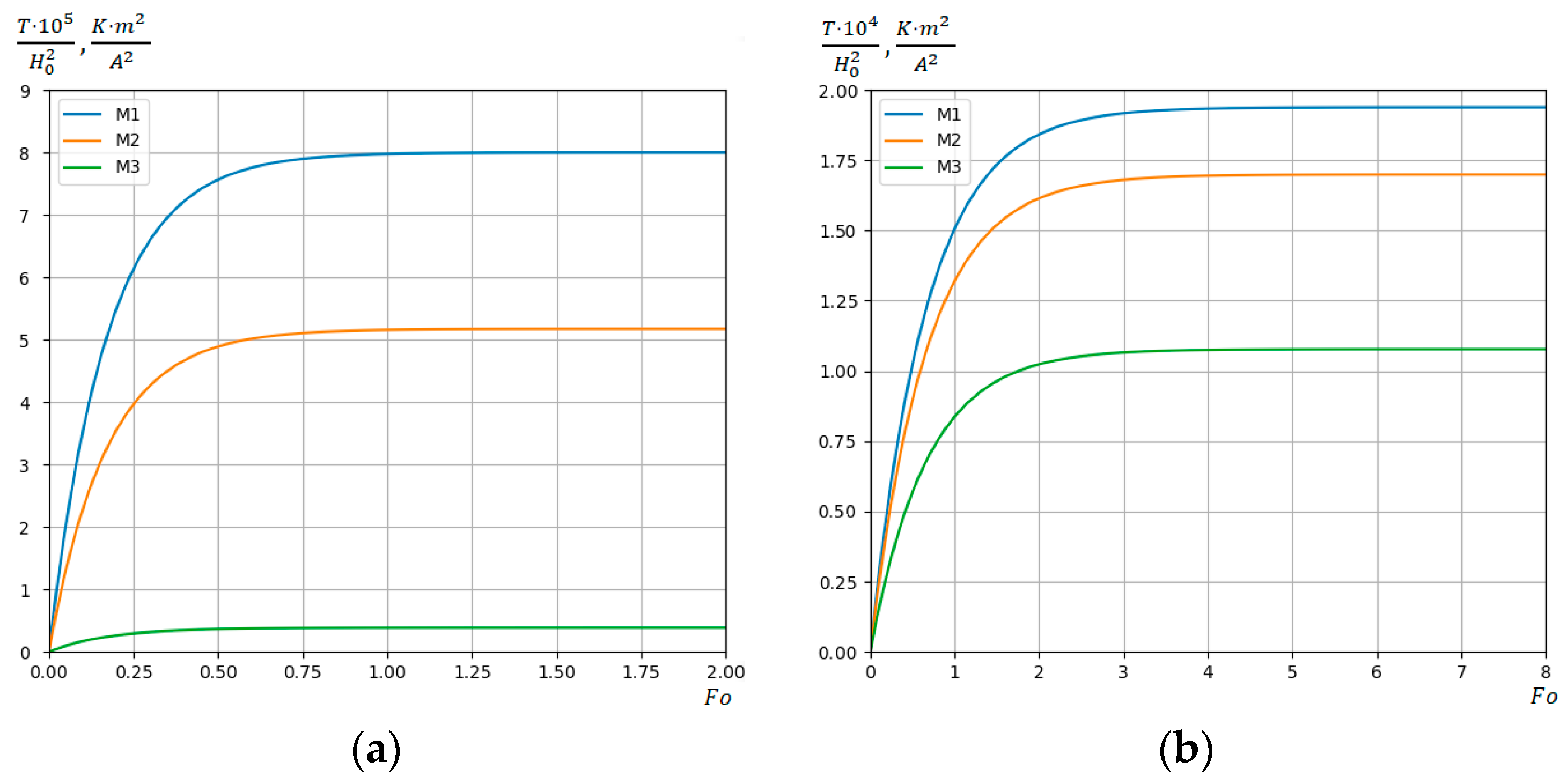
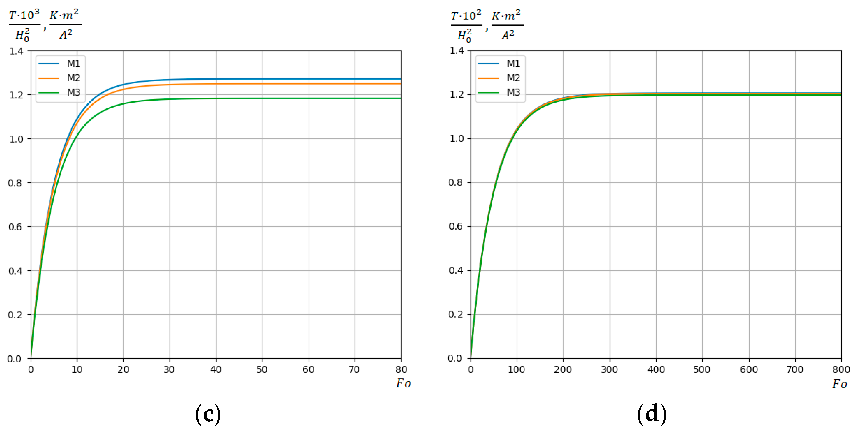
Figure 2a–d show the change of temperature T / H 0 2 in the dimensionless Fourier time F o during near-surface induction heating by quasi-steady EMF at different values of Biot numbers B i = 100 , B i = 1 , B i = 0.1 , B i = 0.01 . The temperature is calculated at characteristic points M 1   ( 0.25   d ,   0.25 ) , M 2   ( 0.5   d ,   0.5 ) , and M 3   ( 0.9   d ,   0.9 ) of the cross-section of the steel strip. Expression T / H 0 2 still has the dimension K m 2 / A 2 . The temperature of the strip T is accordingly measured in Kelvin degrees K .   In the following, we denote the dimensionless time Fo for the temperature to reach its maximum value as Fo*.
It follows from the analysis of the graphs in Figure 2 that the change in temperature T / H 0 2 of the steel strip in time F o in the case of near-surface induction heating significantly depends on the B i value of the Biot number. At B i = 100 , time F o * of the temperature reaching its maximum value equals F o * = 1 ; at B i = 1 , time F o * = 4 ; at B i = 0.1 , time F o * = 40 ; at B i = 0.01 , time F o * = 400 . It means that the lower B i   i s , the higher time F o * is. It is also obtained that the lower B i   i s , the lower is the difference between temperature values T / H 0 2 in the strip cross-section points M 1 ,   M 2 ,   a n d   M 3 selected for analysis, and, at B i = 0.01 (Figure 2d), temperature values in these points are practically identical. This is due to the fact that, at B i = 0.01 , the temperature regime of the strip is close to the heat insulation of its external surfaces.
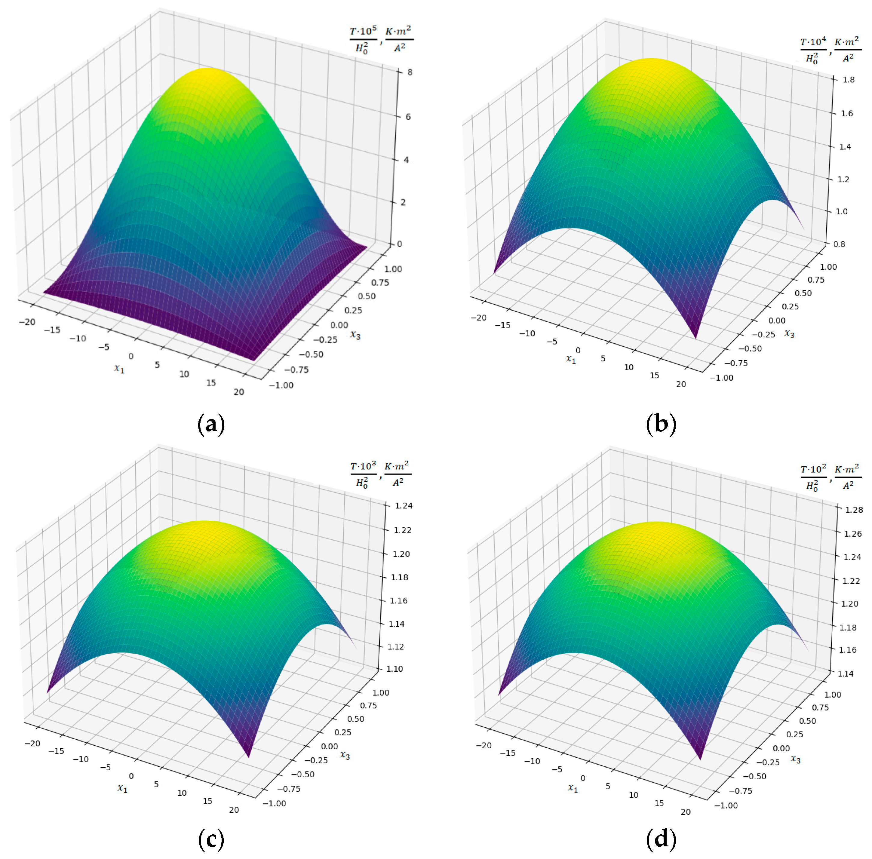
Figure 3a–d show the distribution of temperature T / H 0 2 over the steel strip cross-section area at time points F o = F o * in the case of near-surface induction heating (parameter δ 0 = 0.1 ) at the following Biot number values: B i = 100 , B i = 1 , B i = 0.1 , and B i = 0.01 .
It is reasonable to conclude that the maximum temperature values are reached in the center of the cross-sectional rectangle, and its minimum values are reached at the corner points of the strip cross-section. The shape of the distribution surfaces for all selected B i values is practically the same, and the maximum temperature values T / H 0 2 increase as B i decreases.
Let us present the study results of the temperature regimes of the steel strip under consideration in the case of in-depth induction heating by a quasi-steady EMF. In Figure 4a–d, a change in the temperature T / H 0 2 in Fourier time F o is shown at different Biot values of B i =   100 , B i = 1 , B i = 0.1 , and B i = 0.01 in characteristic steel strip cross-section points M 1 , M 2 , and M 3 selected for analysis.
As in the case of near-surface induction heating, it is obtained that time F o * of temperature T / H 0 2 reaching its maximum value depends on the values of the Biot number B i . The F o * times for the selected values B i = 100 , B i = 1 , B i = 0.1 , and B i = 0.01 during near-surface and in-depth induction heating are the same.
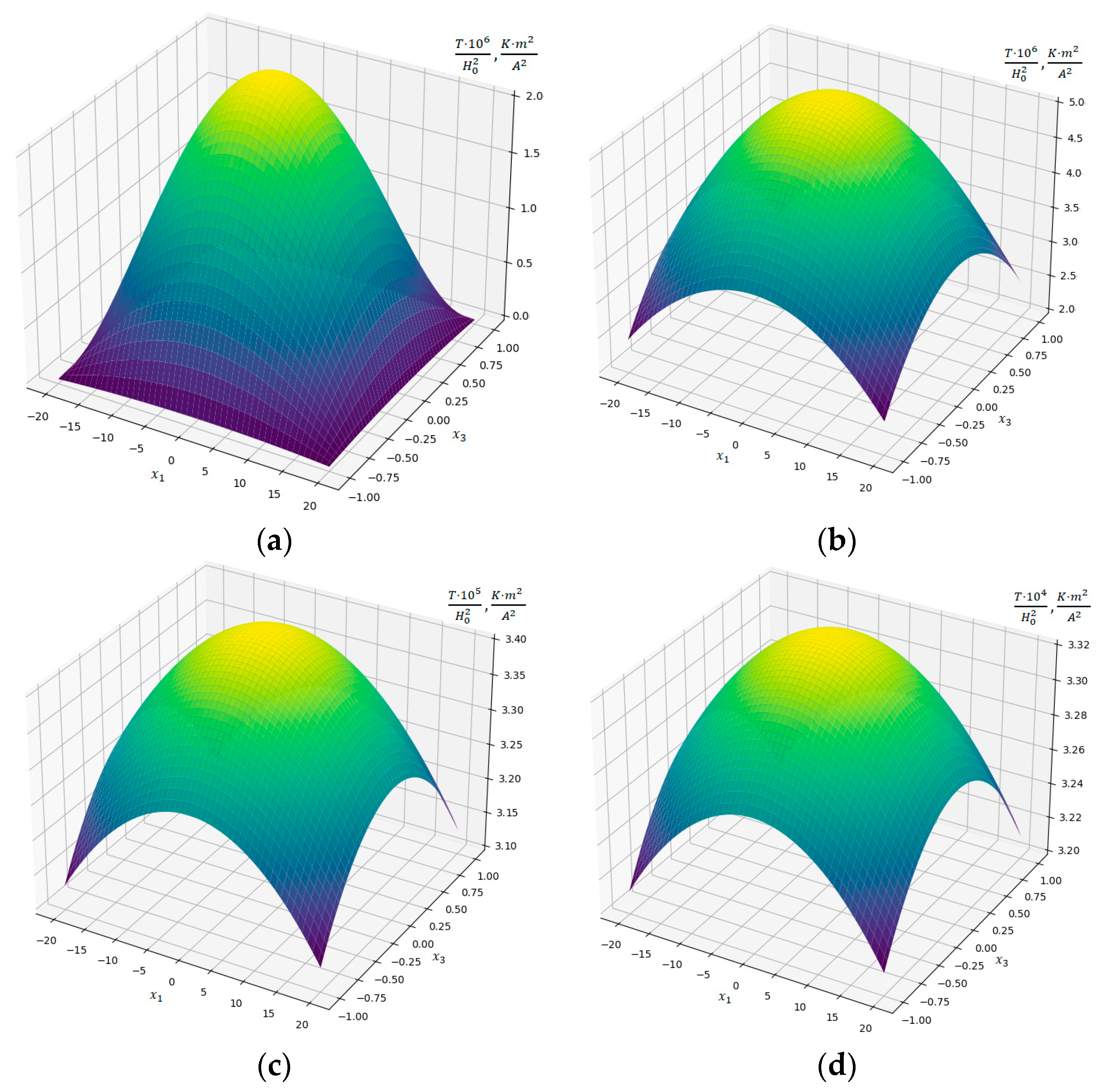
Figure 5a–d illustrate the distribution of temperature T / H 0 2 over the steel strip cross-section area at times F o = F o * in the case of in-depth induction heating at Biot number values B i = 100 , B i = 1 , B i = 0.1 , and B i = 0.01 .
As in the case of near-surface induction heating, maximum temperature values are reached in the center of the cross-section, and its minimum values are reached at its corner points. The geometric shape of the temperature T / H 0 2 distribution surface practically does not differ from Figure 3.
From a comparative analysis of the temperature regimes of steel strip near-surface and in-depth heating, the following patterns are revealed:
(1)
After comparing Figure 2 and Figure 4, it is established that the maximum values of temperature T / H 0 2 depend on parameter δ 0 . In particular, during in-depth induction heating at δ 0 = 1 , maximum temperature T / H 0 2 values are approximately 40 times lower than corresponding temperature T / H 0 2 values during near-surface induction heating at δ 0 = 0.1 ;
(2)
While near-surface strip heating at H 0 = 1.16 1 0 3   A / m and B i = 0.1 , temperature T of the steel strip acquires a value that is close to melting point T s t e e l * 1670   K of the selected stainless steel of which the strip is made. And, at B i = 0.01 , the steel melting point is reached at H 0 = 3.73 1 0 2   A / m ;
(3)
In the case of in-depth heating of the strip, the melting point of the selected stainless steel is reached at the value of magnetic field strength H 0 = 7 1 0 3   A / m for B i = 0.1 and at H 0 = 2.27 1 0 3   A / m for B i = 0.01 ;
(4)
To achieve higher maximum values of strip heating temperature, it is advisable to use near-surface heating.

6. Conclusions

In this paper, the initial-boundary value problem for temperature determination based on a two-dimensional mathematical model of induction heating for a conductive strip under quasi-steady EMF is considered. Components of the magnetic field intensity vector tangent to the base of the strip and the temperature are defining functions. A specially developed method, combining analytical and numerical approaches, is used to study the model. General solutions are obtained using cubic polynomial approximation for the defining functions based on the thickness variable, the finite integral transformation by the transverse variable, and the Laplace integral transformation on time, whereas temperature regimes of the strip are analyzed numerically. Thus, the class of mathematical models of induction heating that can be studied by analytical and numerical methods has been expanded for the case of using quasi-steady EMF for heating.
The results from computer analysis of the temperature regimes of steel strip induction heating under a quasi-steady EMF are the following:
(1)
Critical values of H 0 and B i parameters enabling the steel heating temperature to achieve the melting point of the stainless steel under consideration at times F o = F o * are obtained;
(2)
At a decreasing Biot number B i , the temperature T / H 0 2 maximum value increases in both cases of near-surface and in-depth heating;
(3)
Maximum temperature values for all considered values of the Biot number B i increase at a decreasing induction heating parameter δ 0 . This regularity is due to the fact that, with a decrease in the parameter δ 0 , the frequency of the carrier electromagnetic oscillations increases, and therefore the amount of Joule heat that the EMF introduces into the band increases.
The discovered regularities in the temperature regimes of steel strip near-surface and in-depth induction heating bring us to the conclusion that the use of near-surface induction heating is more effective for achieving a temperature that equals the melting point of the selected stainless steel. The results from computer analysis can be a theoretical basis for choosing optimum temperature regimes for the induction heating of steel strip under a quasi-steady EMF. In practice, these results can be used in industrial productions, operations, and maintenance of elements of technological equipment containing conductive strips. A similar approach can be used in the heat treatment of other metals with a conductive strip-type structure using the induction heating process. In addition, the methodology developed by the authors can serve as the basis for creating appropriate software for calculating the optimal parameters of the induction heating modes considered in this paper.

Author Contributions

Conceptualization, R.M., P.P. and A.C.; methodology, R.M., P.P. and M.V.; validation, M.L., N.M. and A.S.; investigation, P.P., M.V. and A.C.; writing—original draft preparation, M.V. and A.S.; writing—review and editing, R.M., P.P. and A.C.; visualization, N.M., A.C. and A.S.; project administration, R.M., P.P., A.C. and M.L.; funding acquisition, M.L. All authors have read and agreed to the published version of the manuscript.

Funding

This research received no external funding.

Data Availability Statement

Data is contained within the article.

Conflicts of Interest

The authors declare no conflicts of interest.

References

  1. Chaban, A.; Lukasik, Z.; Lis, M.; Szafraniec, A. Mathematical Modeling of Transient Processes in Magnetic Suspension of Maglev Trains. Energies 2020, 13, 6642. [Google Scholar] [CrossRef]
  2. Holman, J.P. Heat Transfer; McGraw Hill: New York, NY, USA, 2009. [Google Scholar]
  3. Hetnarski, R. Encyclopedia of Thermal Stresses; Springer: Dordrecht, The Netherlands, 2014. [Google Scholar] [CrossRef]
  4. Lupi, S. Fundamentals of Electroheat, Electrical Technologies for Process Heating; Springer: Cham, Switzerland, 2017. [Google Scholar] [CrossRef]
  5. Rudnev, V.; Loveless, D.; Cook, R.L. Handbook of Induction Heating, 2nd ed.; CRC Press: Boca Raton, FL, USA, 2017. [Google Scholar] [CrossRef]
  6. Musii, R.; Pukach, P.; Kohut, I.; Vovk, M.; Šlahor, Ľ. Determination and Analysis of Joule heat and Temperature in an Electrically Conductive Plate Element Subject to Short-Term Induction Heating by a Non-Stationary Electromagnetic Field. Energies 2022, 15, 5250. [Google Scholar] [CrossRef]
  7. Musii, R.; Pukach, P.; Melnyk, N.; Vovk, M.; Šlahor, L. Modeling of the Temperature Regimes in a Layered Bimetallic Plate under Short-Term Induction Heating. Energies 2023, 16, 4980. [Google Scholar] [CrossRef]
  8. Hachkevych, O.; Musii, R. Mathematical modeling in thermomechanics of electroconductive bodies under the action of the pulsed electromagnetic fields with modulation of amplitude. Math. Model. Comput. 2019, 6, 30–36. [Google Scholar] [CrossRef]
  9. Milošević-Mitić, V.; Maneski, T.; Andjelić, N.; Milović, L.; Petrović, A.; Gaceša, B. Dynamic temperature field in the ferromagnetic plate induced by moving high frequency inductor. Therm. Sci. 2014, 18, S49–S58. [Google Scholar] [CrossRef]
  10. Hetnarski, R.; Eslami, M. Heat conduction problems. Solid Mech. Its Appl. 2019, 158, 133–224. [Google Scholar] [CrossRef]
  11. Zhyltsov, A.V.; Bereziuk, A.O.; Vishtak, T.V. Three-dimensional mathematical model of three-phase heat generator of induction type based on the method of secondary sources. Tech. Electrodyn. 2022, 5, 8–13. (In Ukrainian) [Google Scholar] [CrossRef]
  12. Jankowski, T.A.; Pawley, N.H.; Gonzales, L.M.; Ross, C.A.; Jurney, J.D. Approximate analytical solution for induction heating of solid cylinders. Appl. Math. Model. 2016, 40, 2770–2782. [Google Scholar] [CrossRef]
  13. Milošević Mitić, V.; Kozak, D.; Maneski, T.; Andelić, N.; Gaćeša, B.; Stojkov, M. Dynamic nonlinear temperature field in a ferromagnetic plate induced by high frequency electromagnetic wave. Strojarstvo 2010, 52, 115–124. [Google Scholar]
  14. Vasetsky, Y.; Zaporozhets, A. Approximate Mathematical Models for Analysis of Alternating Electromagnetic Field of Sources Near Conducting Body. Lect. Notes Electr. Eng. 2024, 1070, 33–67. [Google Scholar] [CrossRef]
  15. Vasetsky, Y.; Zaporozhets, A. Penetration of Non-uniform Sinusoidal Electromagnetic Field into Conducting Half-Space. Lect. Notes Electr. Eng. 2024, 1070, 69–92. [Google Scholar] [CrossRef]
  16. Spateri, E.; Ruiz, F.; Gruosso, G. Modelling and Simulation of Quasi-Resonant Inverter for Induction Heating under Variable Load. Electronics 2023, 12, 753. [Google Scholar] [CrossRef]
  17. Gaspare, A.; Sag, M.; Pecha, P. Numerical Modeling of Ferrite Material Impact on the Effectiveness of Induction Heating Process. Commun. Sci. Lett. Univ. Zilina 2015, 17, 12–17. [Google Scholar] [CrossRef]
  18. Drobenko, B.; Vankevych, P.; Ryzhov, Y.; Yakovlev, M. Rational approaches to high temperature induction heating. Int. J. Eng. Sci. 2017, 117, 34–50. [Google Scholar] [CrossRef]
  19. Favennec, Y.; Labbé, V.; Bay, F. Induction heating processes optimization a general optimal control approach. J. Comput. Phys. 2003, 187, 68–94. [Google Scholar] [CrossRef]
  20. Djambazov, G.; Bojarevics, V.; Pericleous, K.; Croft, N. Finite volume solutions for electromagnetic induction processing. Appl. Math. Model. 2015, 39, 4733–4745. [Google Scholar] [CrossRef]
  21. Iagǎr, A.; Abrudean, C.; Diniş, C.; Pǎnoiu, C. Research upon optimization of the volume induction heating process. Metal. Int. 2008, 13, 27–31. [Google Scholar]
  22. Areitioaurtena, M.; Segurajauregi, U.; Akujärvi, V.; Fisk, M.; Urresti, I.; Ukar, E. A semi-analytical coupled simulation approach for induction heating. Adv. Model. Simul. Eng. Sci. 2021, 8, 14. [Google Scholar] [CrossRef]
  23. Barglik, J.; Smalcerz, A. 2.6 Surface Induction Hardening. Ref. Modul. Mater. Sci. Mater. Eng. 2017, 2, 154–170. [Google Scholar] [CrossRef]
  24. Nikulin, I.L.; Perminov, A.V. Mathematical modelling of frequency and force impacts on averaged metal flows in alternating magnetic field. Int. J. Heat Mass Transf. 2019, 128, 1026–1032. [Google Scholar] [CrossRef]
  25. Barglik, J.; Smagór, A.; Smalcerz, A.; Desisa, D. Induction heating of gear wheels in consecutive contour hardening process. Energies 2021, 14, 3885. [Google Scholar] [CrossRef]
  26. Barglik, J. Identification of temperature and hardness distribution during dual frequency induction hardening of gear wheels. Arch. Electr. Eng. 2018, 67, 913–923. [Google Scholar] [CrossRef]
  27. Lee, K.S.; Kim, S.W.; Eom, D.H. Temperature distribution and bending behaviour of thick metal plate by high frequency induction heating. Mater. Res. Innov. 2011, 15 (Suppl. S1), S283–S287. [Google Scholar] [CrossRef]
  28. Iskierka, S.; Iskierka, I. Induction hardening of flat elements in a flow-through method. Prz. Elektrotechniczny 2019, 95, 132–135. [Google Scholar] [CrossRef]
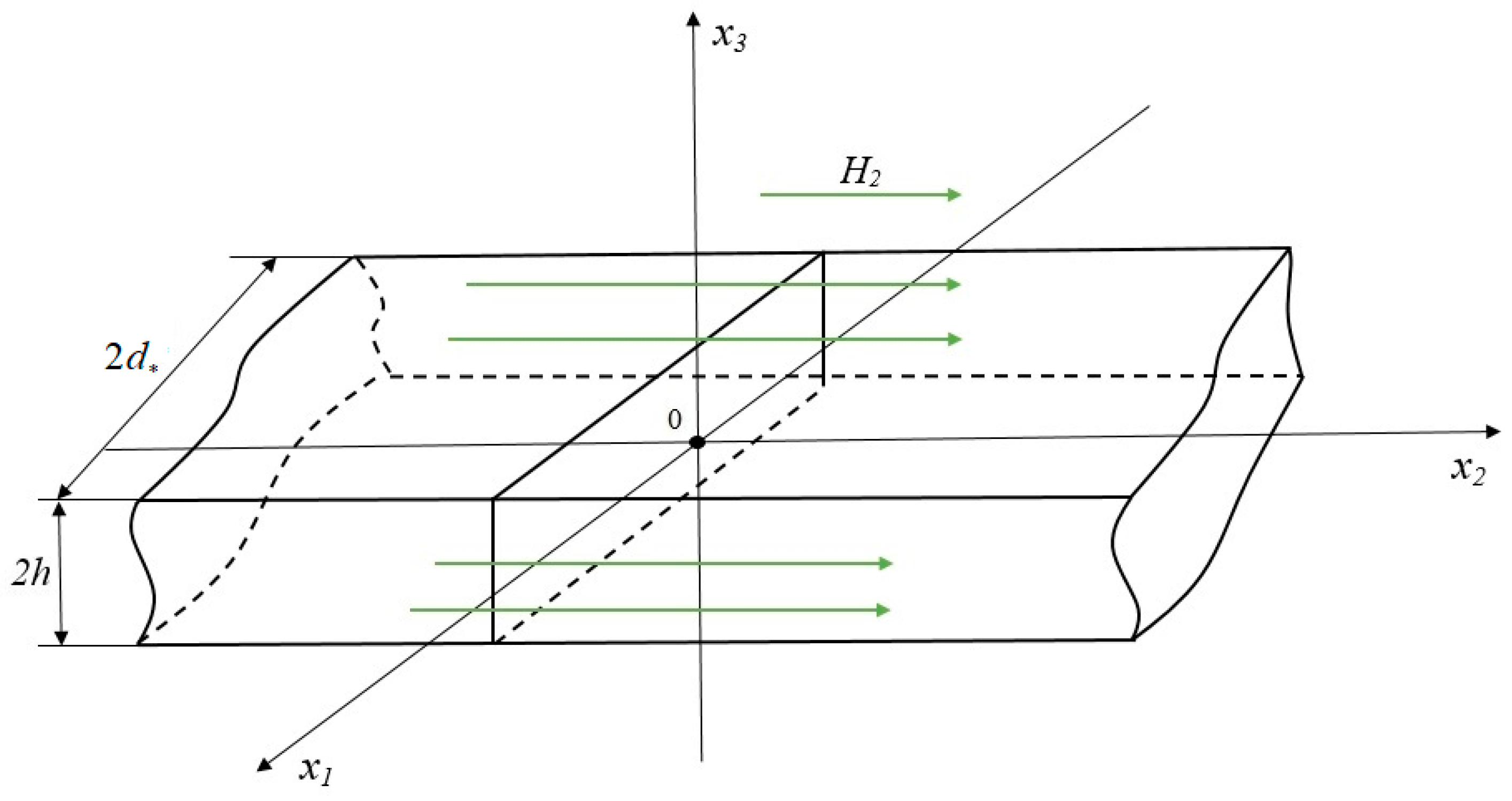
Figure 1. Conductive strip layout.
Energies 17 00366 g001
Figure 2. Change in time F o of temperature T / H 0 2 during near-surface ( δ 0 = 0.1 ) induction heating at Biot values B i = 100 (a), B i = 1 (b), B i = 0.1 (c), and B i = 0.01 (d) in the selected points M 1   ( 0.25   d ,   0.25 ) , M 2   ( 0.5   d ,   0.5 ) , and M 3   ( 0.9   d ,   0.9 ) of strip cross-section.
Energies 17 00366 g002aEnergies 17 00366 g002b
Figure 3. Distribution of temperature T / H 0 2 along the steel strip cross-section area at time points F o = F o * in the case of near-surface induction heating (parameter δ 0 = 0.1 ) at the following Biot number values: B i = 100 (a), B i = 1 (b), B i = 0.1 (c), and B i = 0.01 (d).
Energies 17 00366 g003
Figure 4. Change of temperature T / H 0 2 in time F o during in-depth ( δ 0 = 1 ) induction heating at Biot number values B i = 100 (a), B i = 1 (b), B i = 0.1 (c), and B i = 0.01 (d) in characteristic steel strip cross-section points M 1   ( 0.25   d ,   0.25 ) , M 2   ( 0.5   d ,   0.5 , and M 3   0.9   d ,   0.9 .
Energies 17 00366 g004
Figure 5. Distribution of temperature T / H 0 2 over steel strip cross-section area at times F o = F o * during in-depth induction heating (parameter δ 0 = 1 ) at Biot number values B i = 100 (a), B i = 1 (b), B i = 0.1 (c), and B i = 0.01 (d).
Energies 17 00366 g005
Disclaimer/Publisher’s Note: The statements, opinions and data contained in all publications are solely those of the individual author(s) and contributor(s) and not of MDPI and/or the editor(s). MDPI and/or the editor(s) disclaim responsibility for any injury to people or property resulting from any ideas, methods, instructions or products referred to in the content.