Abstract
The main goals of this research are to develop a method for obtaining the rotor position and speed in a doubly fed induction generator (DFIG) without using sensors in a variable-speed wind turbine installation. The considered method is based on the Model Reference Adaptive System (MRAS). According to this method, electromagnetic torque is used as an error variable for the adaptation process in order to refine the estimate. A good assessment is very important when trying to put into place any strategy that can control the behavior of a DFIG. This method of estimation functions by comparing the actual performance of the DFIG with that of a reference model and adjusting the system parameters to reduce any mismatch between the two. One notable advantage of this developed estimator is its stability across a broad range of speeds. Additionally, it is designed to exhibit resilience in the face of uncertainties in machine parameters. The proportional integral (PI) gains for the MRAS estimator are determined via pole placement. To assess and validate the entire DFIG model and the sensorless estimation method, comprehensive simulations are carried out using MATLAB/Simulink.
1. Introduction
Major concerns about the increasing need for electrical energy have emerged in the last decade. Such an issue is based on the reduction in global hydrocarbon reserves and has also contributed significantly to global warming. In this respect, it is imperative that there should be a search for other sources of power that are not only environmentally safe but also sustainable. The specific field in wind turbines engineering that has been given particular interest is the improvement in their efficiency [1]. Currently, doubly fed induction generators (DFIGs) are widely used for generating variable-speed, constant-frequency electrical power. The DFIG is connected to the utility grid via its stator, requiring it to maintain a fixed output voltage and frequency. Its rotor is connected to the grid through a back-to-back converter system and is supplied by an AC/DC/AC converter [1,2]. In modern DFIG designs, the frequency converter consists of two PWM converters: the rotor-side converter and the grid-side converter, with an intermediate DC voltage link. By precisely controlling these converters on both sides, DFIGs can efficiently harness the maximum amount of energy from the wind, converting nearly 30% of the total power output and reducing system costs, as they operate in a lower power range [3]. A back-to-back converter permits the DFIG to function in both sub-synchronous and super-synchronous modes within a range of one-third above or below synchronous speed. To serve this purpose, however, conventional use of positioning sensors would necessitate additional components, together with alignment requirements that entail increased costs for the system. For that reason, it is better to adopt sensorless approaches for the estimation of rotor speed and position because they are more reliable, the hardware utilized in them is simplified, and they are cheaper compared to their counterparts which require the use of sensors [4]. Sensorless rotor speed and position estimation methods can be broadly categorized into fundamental excitation methods [4,5,6] and saliency and signal injection methods [5,6,7,8,9,10,11,12,13,14,15,16,17]. Fundamental excitation methods include both open-loop and closed-loop estimators. Open-loop speed/position estimation schemes can be further divided into stator flux-based and back electromotive force (EMF)-based methods. Stator flux-based speed estimation has been explored in [4], offering simplicity but suffering from the issue of flux integrator drift. The back EMF-based speed estimation method, as discussed in [5,6,7], demonstrates satisfactory performance at medium to high speeds but becomes challenging to apply at low speeds due to the diminishing back EMF, making speed determination complex. Closed-loop speed and position estimation schemes fall into two main categories: state observer-based methods and Model Reference Adaptive System (MRAS)-based methods. State observer-based methods can be further categorized into stator flux-based observer methods [3,8,9,10] and sliding mode observer methods [11,12,13]. The Extended Kalman filter and observer methods reported in [8,14,15] necessitate knowledge of machine parameters. At standstill or in low-speed regions, the performance of speed and position estimation is impacted by noise, error, and delay. Although the Extended Kalman filter and sliding mode observer methods perform well in these scenarios, they are burdened by high computational complexity and the phenomenon of chattering [16]. MRAS-based methods, discussed in [17,18], have gained attention due to their simplicity in rotor speed and position estimation. This paper aims to fill that gap by proposing an electromagnetic torque-based MRAS estimator for the sensorless control of DFIG systems. The main advantage of this MRAS estimator is its simplicity, as it does not require extensive physical quantities. It simply takes the three-phase rotor current and the reference three-phase rotor voltage as its inputs. The rotor speed estimator of the paper is analyzed for stability through the small signal analysis as the rotor speed angular velocity is the only machine parameter to be estimated through an observer. The proportional integral (PI) gains for the MRAS estimator are optimized to place the roots of the system matrix in predetermined locations through the technique of pole placement. Apart from the guaranteed stability of the MRAS estimator, the speed estimator is also designed to be robust to uncertainty in machine parameters. To evaluate and validate the entire DFIG model and the sensorless estimation method, comprehensive simulations are carried out using MATLAB/Simulink. The subsequent sections of the paper are structured as follows: Modeling of the wind turbine and maximum power point tracking is discussed in Section 2. In Section 3, the modeling and vector control of DFIGs are discussed. The system design of the electromagnetic torque-based MRAS estimator are thoroughly discussed in Section 4. The sensorless control and stability analysis of the system is discussed in Section 5. Section 6 presents the simulation results of the proposed electromagnetic torque-based MRAS estimator for sensorless control of DFIG systems, while the concluding remarks are covered in Section 7.
2. Model of the Wind Turbine and Maximum Power Point Tracking
2.1. Wind Turbine Model
Wind turbines utilize the energy harvested from the wind to generate electricity by driving an electrical generator. The energy available in the wind is calculated as follows:
The mechanical power of the turbine and the torque applied to the shaft can be described by the following equations:
The wind turbine’s power coefficient, , is provided as follows [13,14,15]:
With:
where the speed of the wind turbine is .
Figure 1 illustrates the relationship between the power coefficient () and the tip speed ratio () while keeping the blade pitch angle () constant.
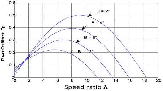
Figure 1.
Wind turbine generator Cp–λ characteristics.
It is evident from the above graph that there exists an optimal value of at which is maximized for a specific wind speed.
Indeed, it is essential to adjust the turbine speed to align with the varying wind speed to maintain the optimal tip speed ratio, ensuring the maximum power capture. This synchronization is necessary for the generator’s active power to be able to match the output power of the turbine.
The gearbox, positioned between the wind turbine and the generator, serves the purpose of matching the relatively slow turbine speed, ωt, with the speed required by the generator, ωm. This gearbox is represented by the following pair of mathematical equations [7]:
The shaft comprises two components of inertia. The first component corresponds to the inertia of the turbine rotor, including the blades and hub. The second component represents the inertia of the generator rotor. In this mechanical model, the total inertia (J) is a sum of the generator’s inertia (Jg) and the inertia of the turbine (Jt), which is transmitted to the generator’s rotor [8]:
where:
Jt: Inertia of the turbine;
Jg: Inertia of the DFIG;
G: Gain of multiplier
2.2. Maximum Power Extracted without Control Speed
In this section, we introduce several approaches for controlling the electromagnetic torque, which, in turn, influences the electromagnetic power conversion to optimize the mechanical speed and maximize electric power generation. When wind speed is measured and the mechanical properties of the wind turbine are known, it becomes feasible to derive real-time optimal mechanical power through the monitoring of maximum power point tracking (MPPT). This optimal mechanical power can be defined as in [10].
The reference value for electromagnetic torque can be set as follows:
where λopt is the optimum tip speed.
Figure 2 illustrates a block diagram constructed based on Equation (10), showcasing the process of maximizing power without the implementation of speed control.
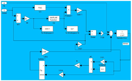
Figure 2.
Block diagram of maximizing the power extracted without speed control.
3. Modeling and Vector Control of DFIG
3.1. Description of DFIG System
A doubly fed induction generator is a specific type of wind turbine generator system. Its primary purpose is to effectively capture wind energy and transfer it to the electrical grid. This technology has become increasingly popular in contemporary wind turbine designs, mainly because of its ability to adapt to varying wind speeds and seamlessly integrate with the grid, as illustrated in Figure 3.
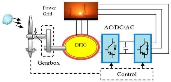
Figure 3.
Simplified diagram of DFIG-based wind generation system.
3.2. Modelling of DFIG
The DFIG model is formulated within the d-q reference frame, and the expressions for the stator and rotor voltages are as follows [12]:
The flux equations are given as follows:
The DFIG electromagnetic torque can be expressed as follows:
The mechanical speed and position are expressed as follows:
The active and reactive stator power equations in the d-q-axis are as follows:
3.3. Field Oriented Control of DFIG
The field orientation control is based on the field dq model, where the reference frame rotates synchronously with respect to the stator flux linkage, with the d-axis of the reference frame instantaneously overlapping the axis of the stator flux. By aligning the stator flux phasor on the d-axis [2,3,4], we have:
Then, from Equations (11) and (17) we obtain:
We consider Rs ids 0 and Rs iqs 0.
So,
Since we operate in a constant condition φs≃cte, we write:
The DFIG is linked to the grid, resulting in:
And
The following equations are derived from (12) and relate the stator currents to the rotor currents:
According to the chosen reference frame, the stator’s active and reactive powers can be expressed as follows:
When the stator currents are substituted into the equations provided in (23), the resulting equation is as follows:
Based on (25), there is an outer control loop. According to rotor currents, the rotor fluxes and voltages can be expressed as follows:
Now by using Equation (26), Equation (11) becomes
where σ = and .
The inner current controller is designed using the expression in (27).
4. System Design of the Electromagnetic Torque-Based MRAS Estimator
Figure 4 provides a schematic representation of the electromagnetic torque-based MRAS estimator within the synchronous d-q reference frame. This research focuses on estimating the rotor speed by analyzing the discrepancies between electromagnetic torques.
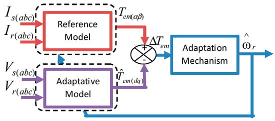
Figure 4.
Proposed electromagnetic torque-based MRAS estimator structure.
In this setup, the real system acts as the reference model, and it operates independently of the estimated parameter, yielding the actual torque (). Meanwhile, the mathematical torque model is treated as an adjustable model that incorporates the estimated rotor speed, thereby generating the estimated electromagnetic torque ().
The error signal is obtained by comparing the reference and estimated electromagnetic torque values and is then subjected to processing through a proportional integral (PI) controller to estimate both the rotor speed and position.
4.1. Reference Model
The electromagnetic torque can be described in an αβ reference frame as follows:
The suggested electromagnetic torque-based MRAS estimator’s reference model uses stator and rotor currents.
4.2. Adjustable Model
The estimated electromagnetic torque can be calculated by using Equations (13) and (23) as follows:
4.3. Adaptation Mechanism
The PI controller is chosen for the adaptation mechanism due to its simplicity. So, the estimated rotor speed can be obtained as follows:
In this system, k1 and k2 represent the integral and proportional gains of a non-linear PI (proportional integral) controller, respectively. denotes the initial estimated rotor speed. To ensure the stability of the proposed MRAS estimator across all operational scenarios, the PI gains are meticulously fine-tuned. This is accomplished through the strategic placement of the system’s poles using pole placement techniques. Additionally, the estimated rotor position is determined by integrating the estimated speed. This integration process is crucial for accurately tracking the rotor’s position in the control system.
where denotes the estimated rotor angle.
5. Sensorless Control and Stability Analysis of the System
Figure 5 presents the proposed electromagnetic torque-based speed estimator. This estimator exhibits strong performance in situations where the machine is stationary or operating at low speeds. It also demonstrates robustness in the face of variations in machine parameters. Importantly, it does not introduce any design complexities into the overall drive system.
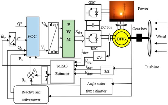
Figure 5.
Control diagram for a sensorless DFIG using an MRAS estimator based on electromagnetic torque.
The estimated values for the rotor speed and electromagnetic torque are substituted for the actual values and stated as follows:
The following steps are used to derive the electromagnetic torque error expression in Figure 4.
And
From (33), the load torque varies according to any changes in the electromagnetic torque until the two torques are equal. Similar to this, a slight difference in the electromagnetic torque error indicates a variance in the rotor speed error.
The state-space representation of the DFIG model in a rotating reference frame, which is used for stability analysis, is formulated as follows:
where
By taking into consideration variations in the d-axis and q-axis rotor currents from a reliable reference point , small signal analysis is used to linearize the DFIG model. This analysis leads to the following results:
where , , .
The result of applying the Laplace transformation to (36) is
It gives
From (37), the transfer functions can be deduced as follows:
and
where
and
Substituting (34) into (39) yields the expression of the electromagnetic error, where the change in speed is given by
From (41), the closed-loop transfer function is given by
Through the use of pole placement, the PI gains of the adaptive mechanism are calculated as = 100 and = 12.
The closed-loop block diagram of the MRAS is shown in Figure 6, which describes the error transfer function (44) between and .

Figure 6.
Block diagram representing closed-loop speed estimator.
Figure 7 displays the root locus plots of the drive system using Equation (44) at the specified operating points, as mentioned in the corresponding figure captions. These plots pertain to the DFIG’s drive under the proposed scheme.
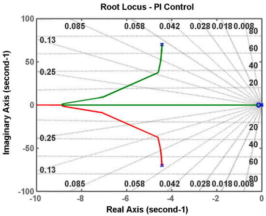
Figure 7.
Root locus plot of Te −MRAS for speed estimation = 78 rad/s, generating mode.
As observed from the plots, the path of the closed-loop poles consistently resides in the left half of the complex s-plane. Consequently, this demonstrates that the system is effectively stable at these specific operating points, given the controller parameters have been appropriately tuned.
6. Simulation Results
The control system has been implemented using the Matlab/Simulink software package, with a sampling time of T = 2 × 10⁻⁵ s. The wind parameters considered are β = 0 (angle of the wind turbine blade), Rt = 3 m (radius of the wind turbine rotor), and the optimal tip speed ratio λopt = 8.1. Additionally, the speed increase ratio of the gearbox is N = 2. The parameters of the DFIG used for simulation can be found in the Table 1.

Table 1.
Parameters of DFIG used for simulation.
It is important to emphasize that the simulation results have been generated without the use of any speed measurements. Instead, the stator windings are directly linked to an infinite power grid. The purpose of this simulation is to evaluate the dynamic performance of sensorless maximum power point tracking. During the simulation, the wind speed applied to the turbine blade varies within the range of 5–11 m/s, as depicted in Figure 8; this setup allows for an assessment of how well the system can track and optimize its power output in response to varying wind conditions.
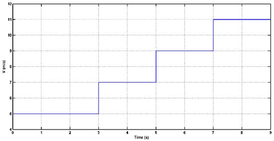
Figure 8.
Wind speed.
In Figure 9, one can observe the dynamic process of the estimated rotor speed as it follows the variations in wind speed. The performance of the Model Reference Adaptive System (MRAS) estimator in tracking the rotor’s rotational speed is depicted, and it is evident that the tracking performance is excellent.
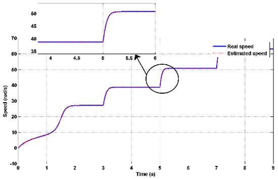
Figure 9.
Actual and estimated rotor speed with zoom.
Figure 10 illustrates the rotor speed error over time. The fact that the rotor speed error remains minimal or within acceptable bounds is a clear indication of the effective tracking performance achieved by the MRAS estimator. This suggests that the estimator is successful in accurately estimating and tracking the rotor speed despite changes in wind speed.
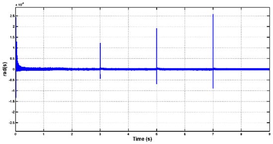
Figure 10.
Error of the estimated speed.
In Figure 11 and Figure 12, one can observe changes in the amplitude of both the rotor and stator currents during periods of active and reactive power variation. It is important to note that the frequency of the stator current remains constant, aligned with the power frequency of the grid. However, the amplitude of the stator current varies as the reference for active power is modified. These variations in current amplitude are a result of adjustments made in response to changes in active and reactive power demands. The control system is likely modulating the current amplitude to meet the desired power output and maintain stability in the electrical grid. These adjustments help ensure that the generator operates efficiently and in accordance with the grid’s requirements.
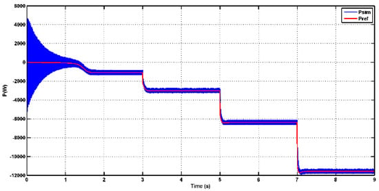
Figure 11.
Phase rotor current.
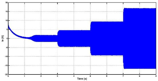
Figure 12.
Phase stator current.
In Figure 13 and Figure 14, one can observe the behavior of stator active and reactive power. These figures demonstrate that the control system effectively tracks the reference values for both active and reactive power, which is indicative of good control performance. Additionally, it confirms the decoupling between active and reactive power, indicating that changes in one parameter do not significantly affect the other. It is noteworthy that in the initial stages, there may be some oscillations during the transient response, especially when there are sudden changes or disturbances. However, as the system stabilizes, these oscillations tend to diminish. Furthermore, it is evident that the active power output of the generator increases proportionally with the increase in wind speed values. This relationship between wind speed and active power output is expected, as higher wind speeds provide more mechanical energy to the turbine, resulting in increased power generation. This behavior aligns with the expected performance of a wind turbine generator system.
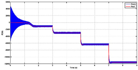
Figure 13.
Stator active output power curve.
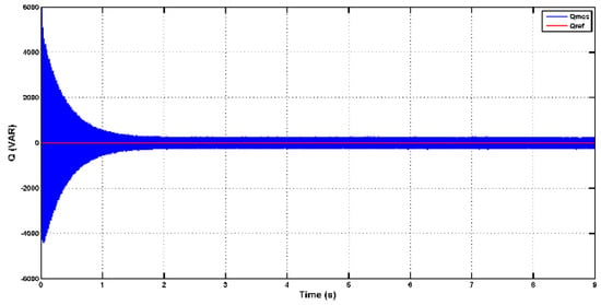
Figure 14.
Stator reactive output power curve.
In Figure 15 and Figure 16, it is evident that when there are sudden variations in wind velocity, the power coefficient (Cp) can rapidly approach the optimal value. Specifically, the power coefficient is maintained at or near its maximum value of Cpmax = 0.48, which corresponds to the optimal tip speed ratio λopt = 8.1.
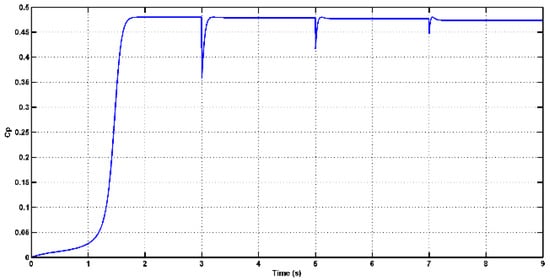
Figure 15.
The power coefficient Cp.
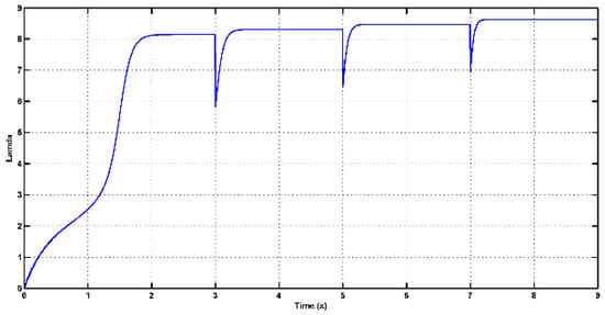
Figure 16.
The tip speed ratio.
This behavior suggests that the control system effectively responds to changes in wind velocity and adjusts the turbine’s operating conditions to maximize the extraction of wind energy. By keeping the power coefficient close to its optimal value, the wind turbine is operating at its peak efficiency, ensuring that a significant amount of available wind energy is converted into electrical power. This is a desirable outcome in wind energy systems, as it allows for the efficient utilization of wind resources.
In Figure 17, the rotor speed–power characteristics of the DFIG are depicted, showing a relationship that aligns with the optimal value. These results reflect the effectiveness of the control system in achieving maximum wind energy tracking. The control mechanism is designed to extract the maximum power from the wind turbine by maintaining the optimal tip speed ratio (λopt). As a result, the generator’s active power output matches the output power of the turbine, ensuring efficient power capture.
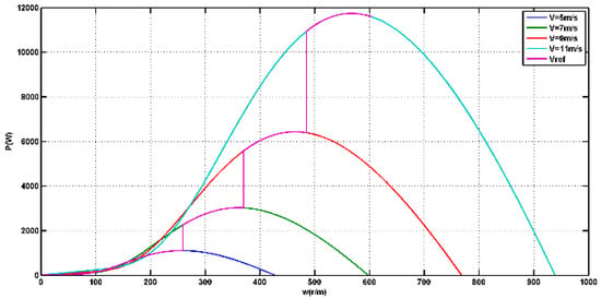
Figure 17.
Wind turbine maximum power trajectory.
Maintaining the optimal tip speed ratio is crucial for maximizing power capture in wind energy systems. It allows the turbine to operate at the most favorable conditions, where the available wind energy is efficiently converted into electrical power. The control system’s ability to track and maintain this optimal operating point contributes to the overall effectiveness of the wind turbine in capturing the maximum possible wind energy.
7. Conclusions
This work presents a simple and reliable electromagnetic torque-based rotor speed estimator using the MRAS technique. The estimator is designed and validated via simulation for the sensorless control of a variable-speed DFIG. The simulation results indicate that the estimator has excellent tracking performance, with minimal error estimation. The PI gains for the MRAS estimator were determined using the pole placement method. The overall drive system demonstrates significant improvements in estimation accuracy, demonstrating stability and robustness under various wind speed environments.
Author Contributions
Conceptualization, A.L.; methodology, A.L.; software, H.S.; validation, A.L. and M.T.B.; formal analysis, A.L., H.S. and M.T.B.; investigation, A.L. and H.S.; resources, A.L. and H.S.; data curation, A.L. and H.S.; writing—original draft preparation, A.L., H.S. and M.T.B.; writing—review and editing, A.L., H.S. and M.T.B.; visualization, A.L. and H.S.; supervision, H.S., M.T.B.; project administration, A.L.; funding acquisition, A.L., H.S. and M.T.B. All authors have read and agreed to the published version of the manuscript.
Funding
This research received no external funding.
Data Availability Statement
The original contributions presented in the study are included in the article, further inquiries can be directed to the corresponding author.
Conflicts of Interest
The authors declare no conflict of interest.
Nomenclature
| vds, vqs | d-q axes stator voltage components. |
| ids, iqs | d-q axes stator current components. |
| ds, qs | d-q axes estimated stator current components. |
| Rs, Rr | Stator and rotor resistances. |
| Ls, Lr | Stator and rotor inductances. |
| Stator and rotor fluxes. | |
| M | Mutual inductance. |
| P | Number of poles. |
| TL | Load torque. |
| Tem | Electromagnetic torque. |
| em | Estimated electromagnetic torque. |
| ωr | Electrical rotor speed. |
| r | Estimated electrical rotor speed. |
| θr | Rotor position. |
| r | Estimated rotor position. |
References
- Muller, S.; Deicke, M.; De Doncker, R.W. Doubly fed induction generator systems for wind turbines. IEEE Ind. Appl. Mag. 2002, 8, 26–33. [Google Scholar] [CrossRef]
- Cardenas, R.; Pena, R.; Proboste, J.; Asher, G.; Clare, J. Sensorless control of a doubly-fed induction generator for stand alone operation. In Proceedings of the 2004 IEEE 35th Annual Power Electronics Specialists Conference (IEEE Cat. No. 04CH37551), Aachen, Germany, 20–25 June 2004; Volume 5, pp. 3378–3383. [Google Scholar]
- Yuan, G.; Li, Y.; Chai, J.; Jiang, X. A novel position sensor-less control scheme of doubly fed induction wind generator based on mras method. In Proceedings of the 2008 IEEE Power Electronics Specialists Conference, Rhodes, Greece, 15–19 June 2008; pp. 2723–2727. [Google Scholar]
- Mohamed, M.; Jemli, M.; Gossa, M.; Jemli, K. Doubly fed induction generator (DFIG) in wind turbine modeling and power flow control. In Proceedings of the 2004 IEEE International Conference on Industrial Technology, Hammamet, Tunisia, 8–10 December 2004; IEEE ICIT’04. Volume 2, pp. 580–584. [Google Scholar]
- Cardenas, R.; Pena, R.; Proboste, J.; Asher, G.; Clare, J. MRAS observer for sensorless control of standalone doubly fed induction generators. IEEE Trans. Energy Convers. 2005, 20, 710–718. [Google Scholar] [CrossRef]
- Payam, A.F.; Jalalifar, M. Robust speed sensorless control of doubly-fed induction machine based on input-output feedback linearization control using a sliding-mode observer. In Proceedings of the 2006 International Conference on Power Electronic, Drives and Energy Systems, New Delhi, India, 12-15 December 2006; pp. 1–5. [Google Scholar]
- Dendouga, A.; Abdessemed, R.; Bendaas, M.; Chaiba, A. Decoupled active and reactive power control of a doubly-fed induction generator (DFIG). In Proceedings of the 2007 Mediterranean Conference on Control & Automation, Athens, Greece, 27–29 June 2007; pp. 1–5. [Google Scholar]
- Aouzellag, D.; Ghedamsi, K.; Berkouk, E. Network power flow control of variable speed wind turbine. In Proceedings of the 2007 International Conference on Power Engineering, Energy and Electrical Drives, Setubal, Portugal, 12–14 April 2007; pp. 435–439. [Google Scholar]
- Aktarujjaman, M.; Haque, M.E.; Muttaqi, K.; Negnevitsky, M.; Ledwich, G. Control Dynamics of a doubly fed induction generator under sub-and super-synchronous modes of operation. In Proceedings of the 2008 IEEE Power and Energy Society General Meeting-Conversion and Delivery of Electrical Energy in the 21st Century, Pittsburgh, PA, USA, 20–24 July 2008; pp. 1–9. [Google Scholar]
- Pena, R.; Cardenas, R.; Proboste, J.; Asher, G.; Clare, J. Sensorless control of doubly-fed induction generators using a rotor-current-based MRAS observer. IEEE Trans. Ind. Electron. 2008, 55, 330–339. [Google Scholar] [CrossRef]
- Thomsen, S.; Rothenhagen, K.; Fuchs, F.W. Online parameter identification methods for doubly fed induction generators. In Proceedings of the 2008 IEEE Power Electronics Specialists Conference, Rhodes, Greece, 15–19 June 2008; pp. 2735–2741. [Google Scholar]
- Ghennam, T.; Berkouk, E.; Francois, B. Modeling and control of a doubly fed induction generator (DFIG) based wind conversion system. In Proceedings of the 2009 International Conference on Power Engineering, Energy and Electrical Drives, Lisbon, Portugal, 18–20 March 2009; pp. 507–512. [Google Scholar]
- Benlaloui, I.; Drid, S.; Chrifi-Alaoui, L.; Ouriagli, M. Implementation of a new MRAS speed sensorless vector control of induction machine. IEEE Trans. Energy Convers. 2014, 30, 588–595. [Google Scholar] [CrossRef]
- Serhoud, H.; Benattous, D. Sensorless optimal power control of brushless doubly-fed machine in wind power generator based on extended kalman filter. Int. J. Syst. Assur. Eng. Manag. 2013, 4, 57–66. [Google Scholar] [CrossRef]
- Serhoud, H.; Benattous, D. Simulation of grid connection and maximum power point tracking control of brushless doubly-fed generator in wind power system. Front. Energy 2013, 7, 380–387. [Google Scholar] [CrossRef]
- Mazouz, F.; Belkacem, S.; Harbouche, Y.; Abdessemed, R.; Ouchen, S. Active and reactive power control of a DFIG for variable speed wind energy conversion. In Proceedings of the 2017 6th International Conference on Systems and Control (ICSC), Batna, Algeria, 7–9 May 2017; pp. 27–32. [Google Scholar]
- Prabhakaran, K.; Karthikeyan, A.; Blaabjerg, F. Laboratory implementation of electromagnetic torque based MRAS speed estimator for sensorless SMPMSM drive. Electron. Lett. 2019, 55, 1145–1147. [Google Scholar] [CrossRef]
- Mbukani, M.; Gitau, M.; Naidoo, R.; Masike, L. A torque-based MRAS estimator for position/speed sensor-less control of DFIG systems. In Proceedings of the 2022 IEEE 1st Industrial Electronics Society Annual On-Line Conference (ONCON), Kharagpur, India, 9–11 December 2022; pp. 1–6. [Google Scholar]
Disclaimer/Publisher’s Note: The statements, opinions and data contained in all publications are solely those of the individual author(s) and contributor(s) and not of MDPI and/or the editor(s). MDPI and/or the editor(s) disclaim responsibility for any injury to people or property resulting from any ideas, methods, instructions or products referred to in the content. |
© 2024 by the authors. Licensee MDPI, Basel, Switzerland. This article is an open access article distributed under the terms and conditions of the Creative Commons Attribution (CC BY) license (https://creativecommons.org/licenses/by/4.0/).