Article

Analysis of the Arc Quenching System of an Arrester Operation Based on a Flow Ultrasound Generator

by
Matvey I. Apolinskiy
1,
Vladimir Ya. Frolov
1,*,
Alexander D. Sivaev
2 and
Evgeniy Y. Enkin
2
1
Higher School of Electric Power Systems, Institute of Energy, Peter the Great St. Petersburg Polytechnic University, 195251 St. Petersburg, Russia
2
Streamer Electric AG, 191024 St. Petersburg, Russia
*
Author to whom correspondence should be addressed.
Energies 2024, 17(19), 4975; https://doi.org/10.3390/en17194975
Submission received: 2 September 2024 / Revised: 21 September 2024 / Accepted: 27 September 2024 / Published: 4 October 2024
(This article belongs to the Section F1: Electrical Power System)

Abstract

:
Flow ultrasound generators are devices that emit high-frequency sound waves due to the hydrodynamic instability of the supersonic flow. In the electric power industry, such generators are used in arc quenching systems of high-voltage gas blast circuit breakers. The design of the flow ultrasound generator includes a nozzle and a hollow cylindrical resonator. Self-oscillations of the sealing waves occur when a supersonic gas jet collides with a resonator. This article is devoted to the analysis of the arrester operation, which has design features of flow ultrasound generators. The paper includes both experimental investigations of the proposed spark gap arrester design and mathematical modeling of the processes occurring in it. A description of the methods used is presented, and a comparison of the time dependences of currents and voltages obtained as a result of experimental studies and as a result of calculations is performed in the next section. The calculation results include oscillograms of the voltage and current, and the plasma temperature distribution in the arrester chamber at different moments of time. The investigations show that the presence of a nozzle and resonator leads to an intensification of the gas dynamic effect on the electric arc.

Graphical Abstract

1. Introduction

The development of switching apparatus for high-current circuits leads us to analyze the operation of arc quenching systems in order to increase their breaking capacity. In this paper, new technical solutions for increasing the breaking capacity of arc quenching devices were developed on the basis of the mathematical modeling of arc quenching systems that are used in lightning protection devices.
The spark gap arrester presented in this paper is a closed-type arrester having in its design the functional elements of flow ultrasound generators, namely a nozzle and a resonator. The hypothesis is that the use of these elements leads to the intensification of electric arc cooling during the arrester operation and an increase in the arc quenching capability of the arrester due to the redistribution of pressure in its volume. As part of the investigation, an experimental study of the spark gap arrester design was performed, and a numerical model was developed, which showed a good agreement with the experiment. It was found that the increase in the arc quenching efficiency of the arrester was 75% compared to an arrester of a similar size, but without elements of flow ultrasound generators. Despite this, it was suggested that the open design will have better arc quenching characteristics compared to the closed one since the pressure gradient between the discharge volume and the external environment will be maintained for much longer during the arrester’s operation. The blowing effect in the closed design of the arrester was maintained until the pressure reached its maximum value, after which pressure redistribution was completed, and the process of electric arc burning was stabilized.
Arresters with functional elements of flow ultrasound generators may find applications either as independent devices for impulse overvoltage protection, as part of arresters with a multi-chamber system, or in arc quenching systems of automatic high-current circuit breakers.
The use of such devices in surge protection circuits is a necessary condition for improving the quality and reliability of a power supply as well as for the protection of important energy facilities [1,2,3,4]. For a long time, active research has been carried out to develop new lightning protection devices and to modernize existing ones.
The main method of follow-current arc quenching in spark gap arresters is gas blasting in combination with dividing the electric arc into many series sections. Multi-chamber systems have been developed and are being improved for this purpose [5,6,7,8,9,10,11,12,13,14,15,16,17,18,19,20,21,22,23,24,25,26,27,28,29,30,31,32]. In these systems, electric arc quenching is provided by a large number of series near-electrode voltage drops as well as by a blowing effect, which creates an extension of each individual section of the electric arc, active cooling, and an increase in electrical resistance. These devices were developed to protect overhead power lines, and they cannot be used indoors or inside buildings since hot exhaust can cause fires and damage equipment. In order to use arresters with a blast type of follow-current arc quenching in indoor spaces, it is necessary to develop systems for cooling hot exhaust.
To protect indoor electrical equipment from lightning overvoltage, surge protection devices in a sealed design are used, namely gas-filled multi-gap arresters [1,33]. Their operating principle is also based on dividing the follow-current arc to separate series sections without emitting exhaust into the external environment. Follow-current arc quenching is provided by total near-electrode voltage drops as well as the use of special gas filling, which helps to increase the arc quenching capability of the arrester.
The development of devices for impulse overvoltage protection that magnetically blow the electric arc into the arc extinguishing grid for follow-current arc quenching is also underway [34,35,36,37,38,39,40,41]. The follow-current arc is divided into series sections in the arc extinguishing grid, causing an increase in the electric arc’s voltage due to series near-electrode voltage drops, providing subsequent arc quenching at a zero current. A disadvantage of electric arc quenching using magnetic blowing is the nonlinear dependence of the blowing force on the value of the follow current. In addition, magnetic blowing systems are complex, from a design point of view.
It is necessary to notice that a follow current that also passes through the arrester to the ground has a frequency of 50 Hz. Therefore, a long duration of the arc current (about 10 ms) will lead to a significant erosion of the arrester electrodes, and there is a need of the quenching of the follow current to increase the erosion resistance of the electrodes [19]. The addition of an asymmetrical gas blast to the arrester design analogous to ones used in arc quenching systems with high-voltage gas-blast circuit breakers will improves the conditions for electric arc quenching.
A numerical model of a surge protection device (SPD) is a combination of gas dynamics, electromagnetic, and heat transfer problems, where the corresponding equations are related by thermodynamic and transport properties. Modern software packages allow for the numerical modeling of physical processes in spark gap arresters, reducing the costs and time for designing new types of lightning protection devices. However, despite this, it is impossible to eliminate experimental research due to the need to justify the choice of the arrester design.
An SPD for low-voltage networks that has the design feature of flow ultrasound generators is presented in this paper.
Flow ultrasound generators are devices that emit high-frequency sound waves due to the hydrodynamic instability of the supersonic flow between the nozzle and the cylindrical resonator [42]. Ultrasound generators are used to intensify chemical reactions for the mechanical cleaning of surfaces and to reduce the viscosity of a medium [43,44]. The design of the simplest ultrasound generator is shown in Figure 1.
The design includes a nozzle and a resonator in the shape of a hollow cylinder. Self-oscillations of the sealing waves occur when a supersonic gas jet interacts with a resonator. The frequency of these self-oscillations depends on the gas flow velocity at the nozzle outlet as well as on the pressure, temperature, gas composition, and geometric parameters of the nozzle–resonator system.
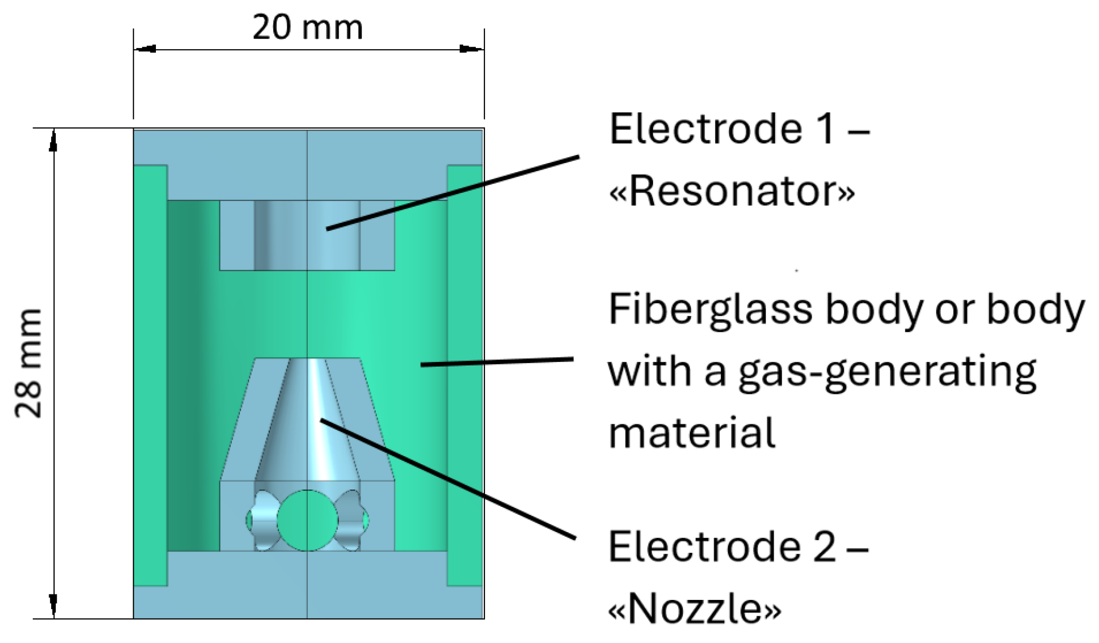
The principle of generating an unstable flow is proposed for application in spark gap arresters using the design features of ultrasound generators, namely a cylindrical resonator and a nozzle, which can also act as a pressure volume. The nozzle and cylindrical resonator also act as electrodes similar to ones in switching devices (gas blast circuit breakers) with a two-way asymmetric blast.
The air gap between the nozzle and the resonator acts as a spark gap. The proposed design of the arrester is shown in Figure 2.
In the normal mode, the spark gap arrester has a large ohmic resistance and a current does not flow through it. However, an electrical breakdown of the spark gap arrester occurs at the moment of lightning overvoltage, and the lightning current is diverted into the ground, thereby protecting the insulation of cable lines and electrical equipment.
It is assumed that the features of the ultrasound generator in the spark gap arrester design will increase its arc quenching capability due to the active gas dynamic action onto the heated channel of the electric arc. A supersonic high-pressure gas jet flowing through the nozzle toward the resonator is necessary for the ultrasound generator operation. In the spark gap arrester, this supersonic gas flow is formed at the arrester during lightning overvoltage due to the thermal expansion of the electric arc plasma.
The prototype of the arrester described above was developed as part of this investigation. An experimental study was also carried out for the presented prototype.

2. Methods

This paper includes both experimental investigations of the proposed spark gap arrester design and mathematical modeling of the processes occurring in it. A description of the methods used is presented, and a comparison of the time dependences of currents and voltages obtained as a result of the experimental studies and as a result of calculations is performed in the next section.

2.1. Experimental Investigation of a Spark Gap Arrester with the Design Features of Ultrasound Generator

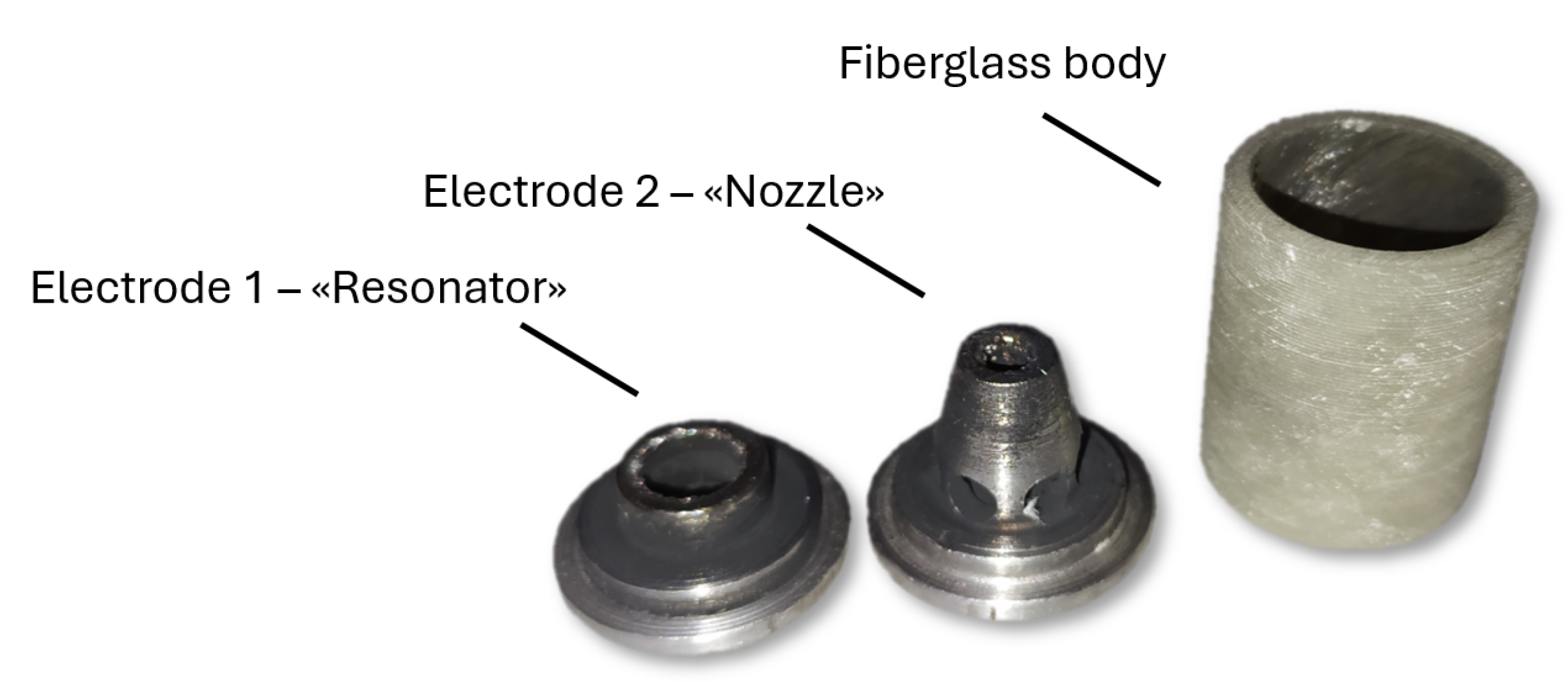
A spark gap arrester sample with the design features of the ultrasound generator was manufactured and tested. Figure 3 shows an example of a spark gap arrester in disassembled state after testing. The example consists of a fiberglass body and two steel electrodes. The electrodes also serve as end caps.
This example was tested in the laboratory of electrical apparatuses of Peter the Great St. Petersburg Polytechnic University using a pulse current generator (GIT-50). The installation was assembled by employees of Streamer Electric AG in St. Petersburg, Russia
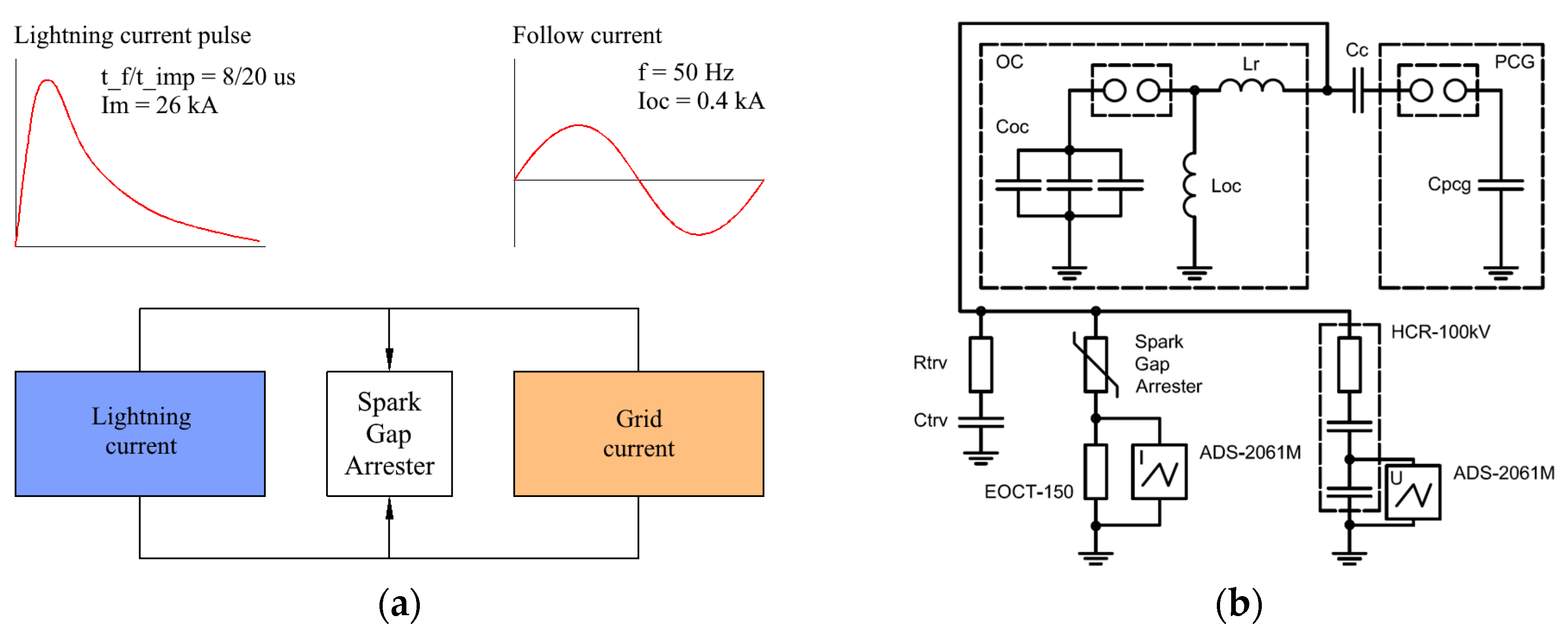
The block diagram and electrical diagram of the high-voltage test bench used for the arrester tests are shown in Figure 4a,b, respectively. The arrester was connected in parallel to a pulse current generator (PCG) and to an oscillatory circuit (OC).
A complex test bench for SPD testing installed in the high-voltage testing laboratory was used for testing the arrester presented in the article. The test bench allows simulating a lightning current pulse with shapes of 8/20 μs, 4/10 μs, and 10/350 μs using a pulse current generator (PCG) as well as a follow current (short-circuit current of the network) with an industrial frequency using an oscillatory circuit (OC).
The electric diagram of the test bench for the arrester study is shown in Figure 4b. The PCG of the test bench produced a pulse current with a maximum value ranging from 2 to 45 kA with an accuracy of ±3% and a shape of 8/20 μs with an accuracy of ±10%. The maximum charging voltage of the PCG was 50 kV. The oscillatory circuit of the test bench is capable of producing the short-circuit current of the network with an amplitude of the first half-wave of up to 2 kA. The maximum charging voltage of the oscillatory circuit was 1.5 kV.
The current through the arrester was measured using an electronic optical current transformer (EOCT-150), with measurement limits ranging from 0 to 150 kA. EOST-150 is produced by «PROFTEK» CJSC, Moscow, Russia. The voltage on the arrester was measured using a voltage divider (HCR-100 kV), with measurement limits ranging from 0.1 to 100 kV. HCR-100 kV is produced by «Energospectechnik» LLC, Vologda, Russia. The voltage and current data were recorded using an ADS-2061M oscilloscope. ADS-2061M is produced by «NPP Elix» CJSC, Moscow, Russia. The oscilloscope error was ±2%.
The gas flow rate and pressure inside the chamber were not measured in this study, since the purpose of the paper is to present a method for electric arc quenching using the design elements of an ultrasonic generator.
The PCG simulated the lightning action, namely, it caused a breakdown of the spark gap of the arrester and the passing of a pulse current of 26 kA, 8/20 μs. The OC simulated the action of an electric network, namely, the passing of a follow current of 50 Hz.
There are three possible scenarios for the arrester operation. The first one is impulse quenching that is characterized by only the pulse current passing through the arrester and by the absence of a follow current [3,13,14]. The second case is zero quenching; both the pulse current and the follow current pass through the arrester, but the quenching of the follow current is carried out at the first zero of the current [15]. The third case is the absence of the quenching of the follow current. This is an emergency. Most arresters are designed for zero quenching, but there are also developments of arresters that are designed for impulse quenching.
The magnitude of the follow current through the test sample as determined by the charging voltage of the OC capacitor of the high-voltage test bench. In the performed tests, the OC charging voltage was 200 V, which corresponded to the follow current through the arrester with a magnitude of 0.5 kA that was followed by zero quenching. A numerical model of the presented spark gap arrester was developed on the basis of the experimental investigation.

2.2. Numerical Modeling of the Spark Gap Arrester

To study thermal, gas dynamic, and electromagnetic processes inside the proposed spark gap arrester, a three-dimensional, unsteady numerical model was developed using the COMSOL Multiphysics 6.2 software package. The numerical modeling of the arc discharge was largely based on the papers [13,16,17,18,19,20,21,22,23,24].
The numerical model was based on the following assumptions: the plasma was in a state of local thermodynamic equilibrium; the erosion of the materials of the arrester chamber was not taken into account, i.e., pure air was considered as a medium inside the spark gap arrester; near-electrode processes were taken into account as an additional resistance factor of the arrester; the plasma flow was laminar; and plasma motion occurred due to thermal expansion only, i.e., electromagnetic forces were not taken into account. To initialize the electric arc, a channel was created between the electrodes with non-zero initial conductivity, i.e., breakdown processes in the spark gap were not considered.
The numerical model was based on a system of magnetohydrodynamics (MHD) equations. Below are the basic equations.
Continuum equation:
ρ t + · ρ u = 0 ;
Motion equation:
ρ u t + ρ u · u = · p I + μ u + u T 2 3 u I ;
Energy equation:
ρ C p T t + ρ C p u · T + · k T = σ E 2 · q r a d ;
Equation of state:
ρ = M n ( T , p ) p A R T ;
Equations of the Maxwell system:
· J = 0 ; J = σ E + D t ; E = V .
Equations (1)–(5) include the following physical quantities: T is the plasma temperature; u is the plasma velocity; p is the plasma static pressure; M n ( T , p ) is the plasma molar mass; C p ( T , p ) is the plasma specific heat; k ( T , p ) is the plasma heat conductivity; σ ( T , p ) is the plasma electrical conductivity; μ ( T , p ) is the plasma dynamic viscosity; q r a d is the heat flux due to radiative transfer; J is the electric current density; E is the electric field intensity; D is the electric displacement vector; and V is the scalar electric potential.
The main thermophysical properties of air plasma as functions of pressure and temperature were taken from the papers [45,46,47].
Since the operation of the arrester is an extremely fast process [25,26,27,28,29], the predominant mechanism of heat transfer is radiation. To address this, the radiation transfer equation (RTE) for the spectral intensity of radiation is introduced to the system of MHD Equations (1)–(5):
s · I ν r , s = k ν I ν b T I ν r , s ,
where I ν r , s is the radiation intensity in the s direction from the point, r , with a frequency, ν ; k ν is the absorption coefficient of the medium, m−1; and I ν b T is the Plank function:
I ν b T = 2 h c 2 ν 3 exp h ν k T 1
where h is the Plank constant; c is the speed of light; and k is the Boltzmann constant.
Since the solution of the radiation transfer Equations (6) and (7) requires significant computational resources, it is important to find an acceptable compromise between the accuracy of the solution and computational costs. The approach proposed in articles [30,48] was applied to the presented model, which involves the use of two spectral bands to describe the coefficient of the effective absorption of air plasma, namely a low-frequency band and a high-frequency one. The high-frequency band ranged from λ = 0 nm to λ = 120 nm, with an average absorption coefficient of α = 2000 m−1. The low-frequency band ranged from λ = 120 nm to λ = 1 mm, with an average absorption coefficient of α = 50 m−1.
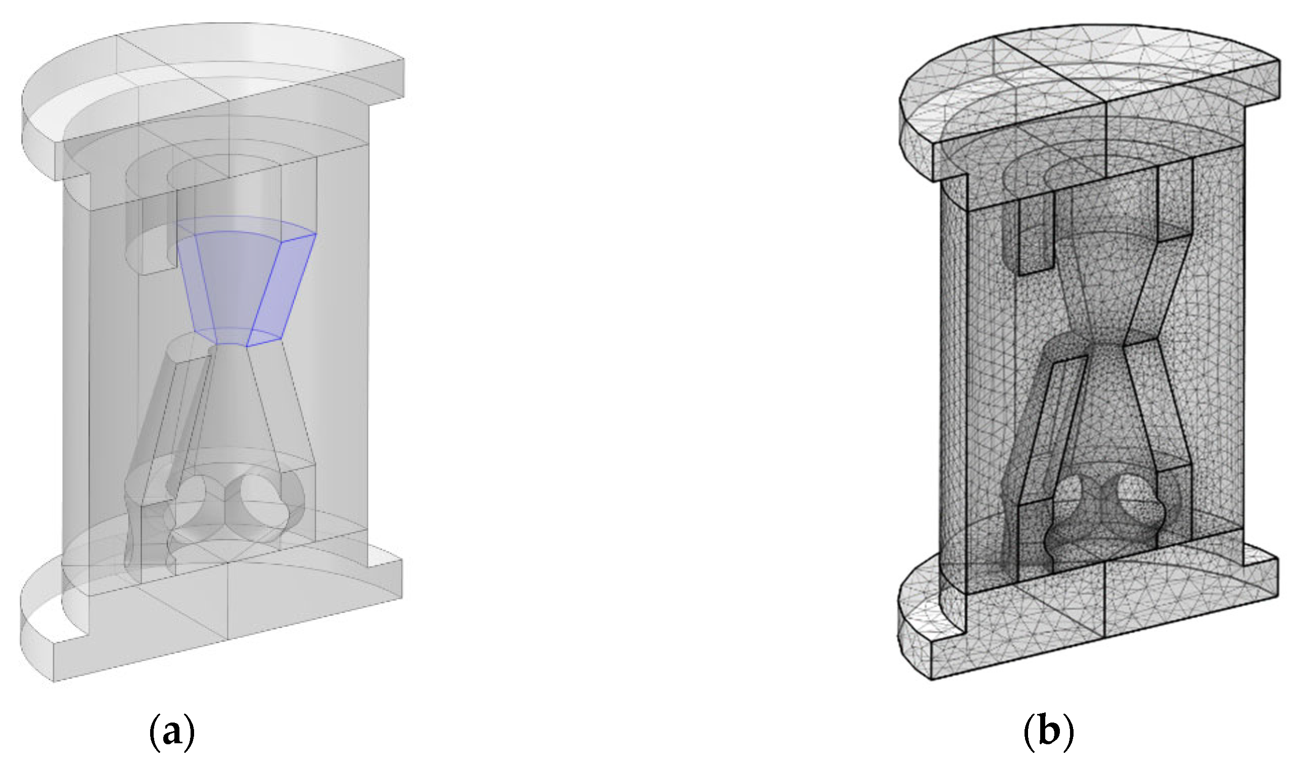
The geometry values of the spark gap arrester and the calculation mesh are shown in Figure 5a. The highlighted blue area is a channel with non-zero initial conductivity for the initialization of the electric arc. The additional electrical conductivity in the selected area varies linearly in time from 100 S/m at the initial time to 0 S/m at the time of 10 μs, and the total electrical conductivity in the channel varies according to the following equations:
σ = σ T , p 1 e 7 · t + 100 ,   t 10   μ s ; σ = σ T , p ,   t > 10   μ s .
The near-electrode processes in the numerical model were taken into account as a contribution to the resistance of the arrester. According to the book [49], the voltage drop at the cathode is 16 V, and it is 4 V in the case of a unipolar pulse. In the numerical model, the additional voltage drop is taken into account according to the following equations:
R e = 4 + 16 I p ,   R e < 10000   Ω R e = 10000   Ω ,   R e 10000   Ω
The mesh for calculations consisting of 258,395 tetrahedra is shown in Figure 5b.
Since the spark gap arrester has a closed design, the “Wall” condition applies to all internal walls, except for the symmetry surface, for which the “Symmetry” condition applies. The initial pressure inside the spark gap arrester is 1 atmosphere.
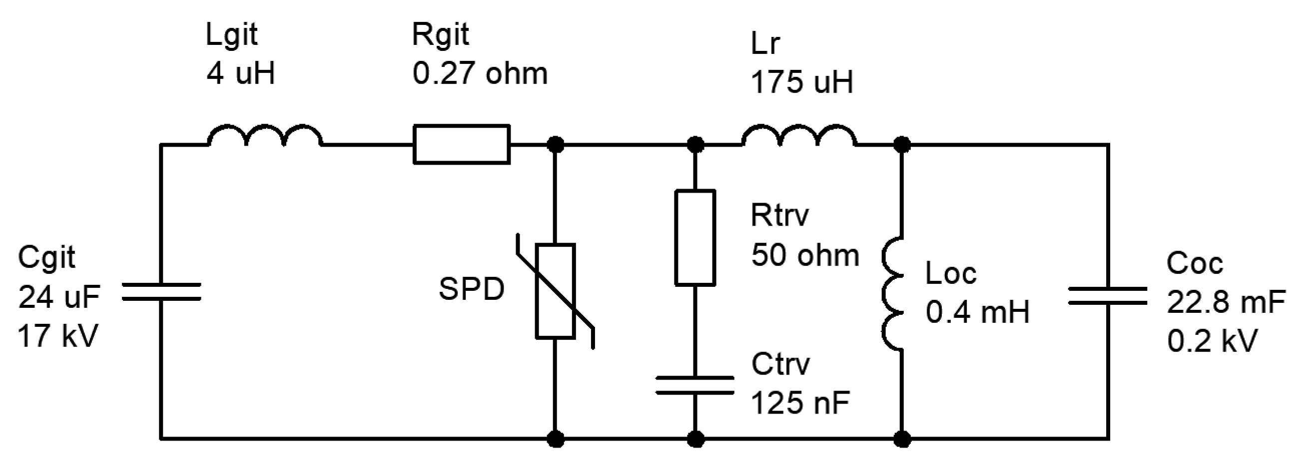
A “Terminal” boundary condition was set on the end face of one of the electrodes, which allows one to set the value of the current across the boundary. The magnitude of this current was modeled using a simulation scheme of PCG and OC, which is shown in Figure 6. A boundary condition of zero potential, i.e., “Ground”, was set on the end face of the second electrode. The circuit parameters fully corresponded to the parameters that were used during the experimental investigations of the presented design of the spark gap arrester.
The system of Equations (1)–(6) was solved by the finite element method in the COMSOL Multiphysics software package.

3. Results and Discussion

The main results are shown in Figure 7, Figure 8, Figure 9 and Figure 10.
Figure 7 shows comparisons of the time dependences of the current and voltage obtained as a result of numerical modeling and as a result of the experiment.
The results of the numerical simulation are consistent with the results of the experimental study, with a discrepancy of no more than 22%. This discrepancy may be related to the accepted assumptions when solving the radiation transfer equations.
Figure 8 shows the temperature distributions at different time points obtained as a result of the numerical simulation. The obtained results allow us to evaluate the operating dynamics of the spark gap arrester with the design features of flow ultrasound generators, and to conclude that a strong gas dynamic effect is exerted on the electric arc during the spark gap arrester’s operation, which can potentially contribute to an increase in the arc quenching capability of the spark gap arrester.
An electric arc ignites after spark gap breakdown, which is accompanied by the thermal expansion of the gas. The nozzle and the resonator act as additional pressure volumes, but since the size of the resonator is smaller than the size of the nozzle and access to the nozzle is difficult due to the small diameter of the hole, the pressure increase in the resonator outpaces the pressure increase in the nozzle. Therefore, one can see in Figure 8b,c that the electric arc at the time point of 12 μs moves into the external volume of the spark gap arrester and slightly into the nozzle. After 12 μs, the pressure in the arrester is redistributed so that the pressure in the external volume and in the nozzle becomes higher than the pressure in the resonator, which leads to the movement of the electric arc into the resonator, as well as to an increase in its length and electrical resistance (see Figure 8d,e). At this point in time, the remaining voltage in the arrester reaches its maximum value of 200 V, which is shown in both the calculated and experimental graphs. At the same time, the pressure in the arrester reaches its peak, stabilizes, and gradually decreases (see Figure 9a).
The arc of the follow current stabilizes, which is reflected in Figure 8f–h, and the arrester voltage decreases until the arc is quenched at zero. It is worth noting that, as the arc of the follow current stabilizes, the arc moves along the annular edge of the electrodes in the spark gap—see Figure 8i–k.
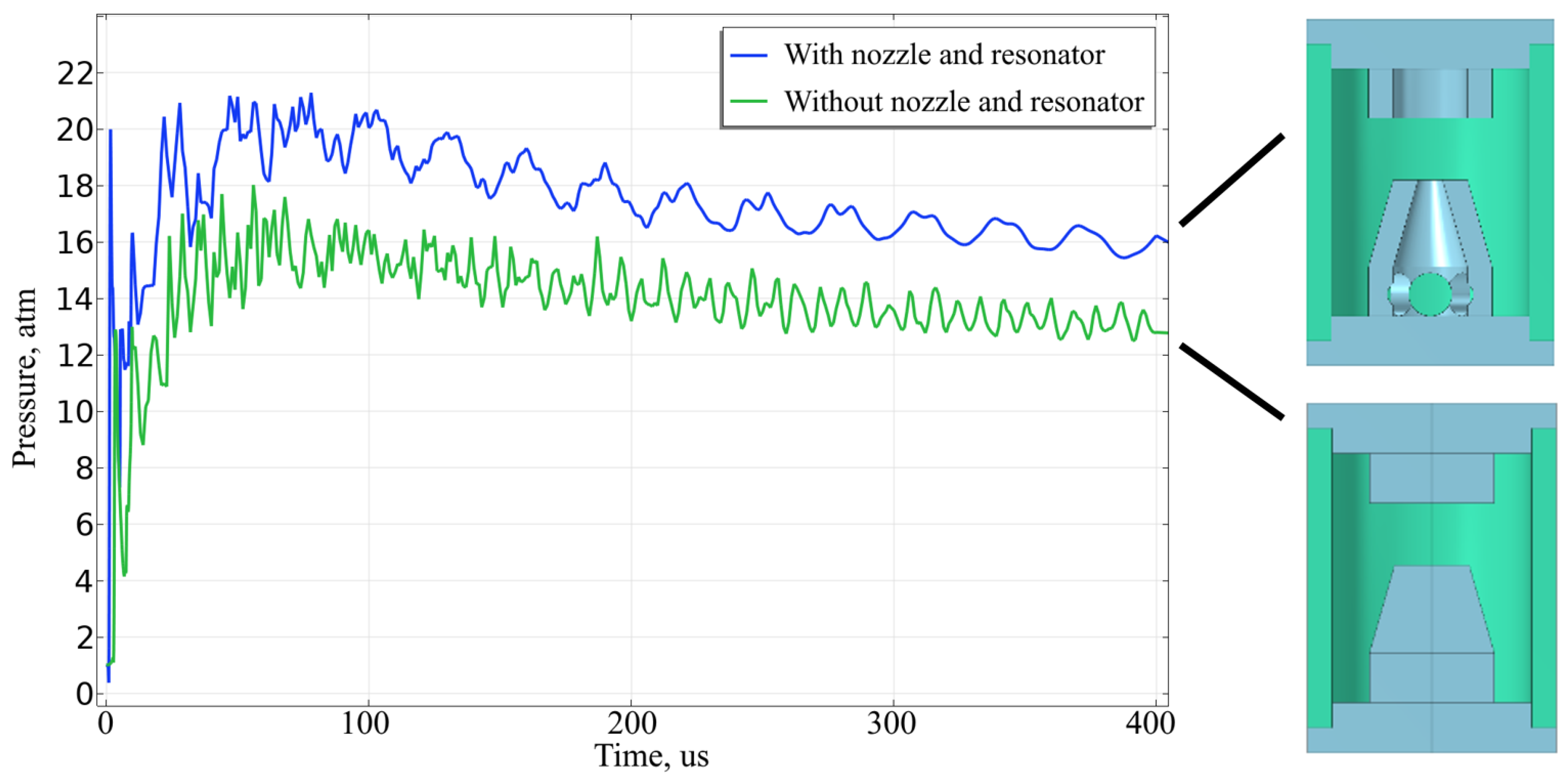
In many respects, it can be concluded that the addition of structural elements of flow ultrasound generators to the design of a closed arrester contributes to an increase in the arc quenching capability of the arrester by 75%. The design of the spark gap arrester without the nozzle and the resonator demonstrated impulse quenching at the oscillatory circuit capacitor voltage of UCoc = 80 V, while the spark gap arrester with the nozzle and the resonator was UCoc = 140 V. This improvement is due to the redistribution of gas flows between the internal volumes of the arrester as well as the intensification of the impact on the electric arc, which led to an increase in the total energy dissipation and an increase in the pressure in the arrester chamber by 18.1%. Figure 10 shows the time dependencies of pressure in the spark gap region of spark gap arresters with and without a nozzle and resonator.
Adding a nozzle and a resonator to an open structure arrester can help increase the arc quenching capability of the arrester to an even greater extent, since a constant pressure gradient is maintained between the internal volume of the arrester and the external environment during the process of the arrester’s operation and the flow of the accompanying current. The high intensity of the impact on the electric arc is maintained, even at the stage of the follow current passing through it, but this requires the development of a hot exhaust cooling system to make it possible to use such an arrester in closed spaces and buildings.
High-frequency components are observed on pressure graphs, but it cannot be unequivocally said that these components are generated by ultrasound due to the presence of a nozzle and a resonator. High-frequency oscillations are associated with the reflection of the shock wave front from the walls of the discharge chamber; the front occurred at the moment the arrester was triggered. This is indicated by the low frequency of pressure fluctuations in the case of the design with the nozzle and the resonator in comparison with the design without these elements. The low frequency of pressure fluctuations is due to the increased path of the shock wave front between reflections from the inner walls of the discharge chamber due to additional pressure volumes.
The generation of ultrasonic radiation has an insignificant effect on the efficiency of electric arc quenching in the spark gap arrester with the nozzle and the resonator due to the transience and instability of gas dynamic processes. The main conditions for the generation of ultrasonic radiation are: the stable outflow of gas from the nozzle at a supersonic constant velocity; certain ratios of nozzle size and distance from the nozzle to the tubular resonator; and the correctly selected size of the tubular resonator [44]. In this design, the gas flow is determined by the current that varies over time during the arrester’s operation. Also, it is necessary to notice that the design of the arrester is fixed, which leads to a rapid decrease in the flow rate as the pressure increases in the the discharge chamber.
Thus, the inclusion of the nozzle and the resonator in the design of the spark gap arrester made it possible to increase the efficiency of electric arc impulse quenching by 75%, but the reason was not the generation of ultrasonic radiation. The main contribution to the increase in efficiency was made by additional pressure volumes created by the nozzle and the resonator. It made it possible to increase the pressure inside the spark gap arrester, which led to an increase in the intensity of the gas dynamic effect on the electric arc.

4. Conclusions

This paper describes the design of a spark gap arrester for impulse overvoltage protection in low-voltage industrial frequency networks, which has the functional features of flow ultrasound generators.
The hypothesis was that adding the functional elements of flow ultrasound generators to the arrester design would increase the efficiency of arc quenching due to the intensification of the gas’s impact on the arc by the ultrasound generation effects. However, it was later discovered for the closed-design arrester that the impact on the arc was intensive only at the first stage of the arrester’s operation due to the redistribution of pressure inside the arrester and until the pressure was equalized. In this regard, an open design may be more promising than a closed one. Despite this, the pressure redistribution during the first stage of the arrester’s operation is sufficient to increase the efficiency of arc quenching by 75% due to an 18.1% increase in the maximum pressure compared to a closed arrester without flow generator elements. The increase in the pressure is associated with the intensification of the impact on the electric arc, as well as an increase in its length and electrical resistance, which ultimately led to an increase in the total energy dissipation.
The generation of ultrasonic flow does not have time to influence the arc quenching capability of the spark gap arrester due to the rapidity and instability of the processes inside the sealed discharge chamber.
The results of the numerical model of the spark gap arrester with a nozzle and a resonator are in good agreement with the results of the experimental study of the prototype, which will allow us to use the calculation model in further studies of arrester designs. We plan to study the open design of the spark gap arrester with structural elements of flow ultrasound generators using a high-speed camera and pressure and temperature sensors to clarify the numerical model and improve the shape of the discharge chamber. Open designs should show better characteristics since pressure differences between the internal volume of the arrester and the external medium will be present throughout the operation of the arrester, but in this case, it will be necessary to solve the problem of cooling the hot exhaust of the arrester. To increase the intensity of arc quenching, we also plan to introduce gas-generating materials into the arrester design, which will increase the intensity of heat exchange with the electric arc.
The application of a nozzle and a resonator as additional pressure volumes to increase the model’s arc quenching capability is not limited to surge protection devices, but can also be used in high-voltage switches to increase their breaking capacity.

Author Contributions

Conceptualization, V.Y.F. and A.D.S.; methodology, V.Y.F., M.I.A., A.D.S. and E.Y.E.; software, M.I.A.; validation, V.Y.F., M.I.A., A.D.S. and E.Y.E.; formal analysis, V.Y.F. and A.D.S.; investigation, M.I.A. and E.Y.E.; resources, E.Y.E.; data curation, M.I.A.; writing—original draft preparation, V.Y.F., M.I.A. and E.Y.E.; writing—review and editing, V.Y.F. and A.D.S.; visualization, M.I.A.; supervision, V.Y.F. and A.D.S.; project administration, V.Y.F. and A.D.S.; funding acquisition, V.Y.F. and A.D.S. All authors have read and agreed to the published version of the manuscript.

Funding

The research was carried out according to the state assignment of the Ministry of Science and Higher Education of the Russian Federation (theme No. FSEG-2023-0012).

Data Availability Statement

Data are contained within the article.

Conflicts of Interest

Authors Alexander D. Sivaev and Evgeniy Yu. Enkin are employed by the company Streamer Electric AG. The remaining authors declare that the research was conducted in the absence of any commercial or financial relationships that could be construed as a potential conflict of interest.

References

  1. Sadkhan, M.M. Application of surge arresters in low voltage network supply to reduce lightning overvoltages. In Proceedings of the Fifth International Engineering Conference on Developments in Civil & Computer Engineering Applications (IEC2019), Erbil, Iraq, 23–25 June 2019; pp. 74–78. [Google Scholar] [CrossRef]
  2. Refiasto, S.; Denov, B.; Suwarno, S.; Zoro, R. Installation of multi chamber arrester to improve lightning reliability performance of distribution lines system in oil and gas area. In Proceedings of the 3rd International Conference on High Voltage Engineering and Power Systems (ICH-VEPS), Bandung, Indonesia, 5–6 October 2023; pp. 258–262. [Google Scholar] [CrossRef]
  3. Wu, D.; Ji, Z.; Wang, J. Simulation and experimental analysis of multi-chamber arc-quenching arresters (MCAA) for 10 kV transmission lines. Energies 2021, 14, 6185. [Google Scholar] [CrossRef]
  4. Kuan, T.; Chew, K.; Chua, K. Surge Protection Device for Ex Application. Adv. Sci. Technol. Eng. Syst. J. 2020, 5, 768–780. [Google Scholar] [CrossRef]
  5. Podporkin, G.; Enkin, E.; Kalakutsky, E.; Pilshikov, V.; Sivaev, A. Lightning protection of overhead lines by multi-chamber arresters and insulator-arresters. In Proceedings of the 30th International Symposium on Lightning Protection, Cagliari, Italy, 13–17 September 2010; p. 7845759. [Google Scholar] [CrossRef]
  6. Kozakov, R.; Khakpour, A.; Gorchakov, S.; Uhrlandt, D.; Ivanov, D.; Murashov, I.; Podporkin, G.; Frolov, V. Investigation of a Multi-Chamber System for Lightning Protection at Overhead Power Lines. Plasma Phys. Technol. 2015, 2, 150–154. [Google Scholar]
  7. Pinchuk, M.E.; Budin, A.V.; Kumkova, I.I.; Chusov, A.N. Studying energy evolution in the discharge chamber of a multichamber lightning protection system. Tech. Phys. Lett. 2016, 42, 395–398. [Google Scholar] [CrossRef]
  8. Frolov, V.Y.; Ivanov, D.V.; Belsky, R.A. Increasing of operation security and of breaking capacity of surge arresters. In Proceedings of the IEEE Russia Section Young Researchers in Electrical and Electronic Engineering Conference (ElConRus 2017)f, St. Petersburg/Moscow, Russia, 1–3 February 2017; Volume 7910861, pp. 1520–1523. [Google Scholar] [CrossRef]
  9. Li, Z.; Fu, J.; Zhou, X.; Feng, Z.; Yao, Y.; Wang, J. Study on arc extinguishing characteristics of multiple series gap under long clearances. AIP Adv. 2022, 12, 055326. [Google Scholar] [CrossRef]
  10. Chusov, A.N.; Podporkin, G.V.; Chistyakov, A.S.; Apolinskiy, M.I.; Frolov, V.Y.; Ivanov, D.V. The application of gas-generating materials for increase of line lightning protection device efficiency. In Proceedings of the Seminar on Industrial Electronic Devices and Systems (IEDS), St. Petersburg, Russia, 27–28 November 2023; pp. 72–77. [Google Scholar] [CrossRef]
  11. Chistyakov, A.; Frolov, V.; Zaretskiy, N.; Chusov, A. The investigation of effect of a multi-chamber arrester mechanical properties on the efficiency of arc extinction. In Proceedings of the Conference of Young Researchers in Electrical and Electronic Engineering (ElCon), St. Petersburg, Russia, 29–31 January 2024; pp. 803–805. [Google Scholar] [CrossRef]
  12. Huang, S.; Wang, J.; Xu, Y.; Li, Z.; Yan, R.; Zhang, Q. The effect of a multi-fracture compression airflow arc-extinguishing structure interrupting the power frequency follow current. AIP Adv. 2020, 10, 035129. [Google Scholar] [CrossRef]
  13. Chusov, A.; Chystiakov, A.; Apolinskiy, M. Application of numerical simulations for improvement of line lightning protection device efficiency. In Proceedings of the 36th International Conference on Lightning Protections, Cape Town, South Africa, 2–7 October 2022; pp. 468–472. [Google Scholar] [CrossRef]
  14. Li, Z.; Wang, J.; Zhou, X.; Huang, S.; Xia, Z. Study on impulse quenching based multichamber arc quenching structure. AIP Adv. 2019, 9, 85104. [Google Scholar] [CrossRef]
  15. Podporkin, G.V.; Enkin, E.Y.; Kalakutsky, E.S.; Pilshikov, V.E.; Sivaev, A.D. Overhead lines lightning protection by multi-chamber arresters and insulator-arresters. IEEE Trans. Power Deliv. 2011, 26, 214–221. [Google Scholar] [CrossRef]
  16. Frolov, V.; Ivanov, D.; Murashov, I.; Sivaev, A. Mathematical simulation of processes in discharge chamber of multi-chamber system for lightning protection at overhead power lines. In Proceedings of the IEEE North West Russia Section Young Researchers in Electrical and Electronic Engineering Conference (ELCONRUSNW 2016), St. Petersburg, Russia, 2–3 February 2016; pp. 562–565. [Google Scholar] [CrossRef]
  17. Guo, Z.; Long, X.; Qian, Z.; Qiu, N. Three dimensional simulation of the arc inside an insulator-arrester with a multichamber system. AIP Adv. 2016, 6, 45117. [Google Scholar] [CrossRef]
  18. Frolov, V.Y.; Ivanov, D.V.; Podporkin, G.V.; Sivaev, A.D. Development of mathematical model of processes in multi-chamber arrester for identification of criteria of arc extinction. In Proceedings of the 2017 International Symposium on Lightning Protection (XIV SIPDA 2017), Natal, Brazil, 2–6 October 2017; pp. 240–243. [Google Scholar] [CrossRef]
  19. Chusov, A.; Rodikova, E.; Murmann, M.; Nordborg, H.; Fuchs, R. A review of progress towards simulation of arc quenching in lightning protection devices based on multi chamber systems. Plasma Phys. Technol. 2017, 4, 273–276. [Google Scholar] [CrossRef]
  20. Frolov, V.; Ivanov, D.; Sivaev, A. Simulation of arc extinction in discharge chambers of lightning protection equipment. In Proceedings of the 10th International Scientific Symposium on Electrical Power Engineering (ELEKTROENERGETIKA 2019), Stara Lesna, Slovakia, 16–18 September 2019; pp. 143–146. [Google Scholar]
  21. Frolov, V.; Ivanov, D.; Sivaev, A.; Chusov, A. Development of two-temperature mathematical model of processes in discharge chamber of multi-chamber arrester operating in conditions of mountain areas. Plasma Phys. Technol. 2019, 6, 135–139. [Google Scholar] [CrossRef]
  22. Liu, Y.; Wu, G.; Liu, K.; Guo, Y.; Zhang, X.; Shi, C. Study on the arc motion characteristics of multi-chamber arrester based on 3D model. IEEE Access 2020, 8, 90035–90041. [Google Scholar] [CrossRef]
  23. Frolov, V.; Ivanov, D.; Sivaev, A.; Chusov, A.; Chistyakov, A.; Rogozhina, A. Mathematical Model of Arc Quenching in the Adjacent Chambers of an RMKE-10 Multichamber Lightning Arrester. Elektrichestvo 2022, 7, 40–51. [Google Scholar] [CrossRef]
  24. Frolov, V.Y.; Ivanov, D.V.; Sivaev, A.D.; Chusov, A.N.; Botvinkin, I.D. Improved mathematical model of the operation of two adjacent chambers of the RMKE-10 multi-chamber arrester for lightning protection of overhead power lines. In Proceedings of the Seminar on Industrial Electronic Devices and Systems (IEDS), St. Petersburg, Russia, 27–28 November 2023; pp. 89–93. [Google Scholar] [CrossRef]
  25. Chusov, A.; Podporkin, G.; Pinchuk, M.; Ivanov, D.; Murashov, I.; Frolov, V. Development of a physical 2-D model for arc quenching chamber of lightning protection multi-chamber systems. In Proceedings of the 33rd International Conference on Lightning Protection (ICLP 2016 33), Estoril, Portugal, 25–30 September 2016; p. 7791509. [Google Scholar] [CrossRef]
  26. Murashov, I.V.; Frolov, V.Y.; Uhrlandt, D.; Gortschakow, S.; Ivanov, D.V.; Sivaev, A.D. Analysis of arc processes in multi-chamber arrester for lightning protection at high-voltage overhead power lines. Plasma Phys. Technol. 2017, 4, 124–128. [Google Scholar] [CrossRef]
  27. Chusov, A.; Pinchuk, M.E.; Budin, A.V. Investigation of altitude dependence of multi-chamber arrester quenching efficiency. In Proceedings of the 11th Asia-Pacific International Conference on Lightning (APL), Hong Kong, China, 12–14 June 2019. [Google Scholar] [CrossRef]
  28. Li, Z.; Wang, J.; Zhou, X.; Huang, S.; Yan, R.; Xia, Z. Influence of chamber structure on arc quenching in multigap system. High Volt. 2020, 5, 313–318. [Google Scholar] [CrossRef]
  29. Chusov, A.; Pinchuk, M.; Ivanov, D.; Frolov, V. Effects of high altitude on multi-chamber arrester performance. In Proceedings of the 35th International Conference on Lightning Protection (ICLP) and XVI International Symposium on Lightning Protection (SIPDA), Colombo, Sri Lanka, 20–26 September 2021. [Google Scholar] [CrossRef]
  30. Muermann, M.; Chusov, A.; Fuchs, R.; Nefedov, A.; Nordborg, H. Modeling and simulation of the current quenching behaviour of a line lightning protection device. J. Phys. D Appl. Phys. 2017, 50, 105203. [Google Scholar] [CrossRef]
  31. Sander, C. Entwicklung eines Simulationsmodells für Schaltlichtbögen in Überspannungsableitern. Ph.D. Dissertation, Technische Universität Braunschweig, Braunschweig, Germany, 2020. [Google Scholar]
  32. Zhang, Y.; Zhang, W.; Ji, J. Study of a Combined Surge Protective Device for a Relay Protection Circuit in a UHV Converter Station. IEEE Access 2020, 8, 159956–159964. [Google Scholar] [CrossRef]
  33. Meppelink, J.; Drilling, C.; Droldner, M.; Jordan, E.G.; Trinkwald, J. Lightning Arresters with Spark Gaps. Requirements and Future Trends of Development and Application. 2000. Available online: https://www.obo.com.tr/fileadmin/default/Downloads/FUNKENS2.PDF (accessed on 12 August 2024).
  34. Huo, J.; Selezneva, S.; Jacobs, L.; Cao, Y. Study of Wall Ablation on Low-Voltage Interruption: The Effect of Stefan Flow. J. Appl. Phys. 2019, 125, 213302. [Google Scholar] [CrossRef]
  35. Fievet, C.; Burrault, M.; Petit, P.; Chevrier, P.; Fleurier, C.; Andre, V. Optical diagnostics and numerical modelling of arc re-strikes in low-voltage circuit breakers. J. Phys. D Appl. Phys. 1997, 30, 2991. [Google Scholar] [CrossRef]
  36. Rümpler, C. Lichtbogensimulation für Niederspannungsschaltgeräte. Ph.D. Dissertation, Technische Universität Ilmenau, Ilmenau, Germany, 2009. [Google Scholar]
  37. Eichhoff, D.; Kurz, A.; Kozakov, R.; Gott, G.; Uhrlandt, D.; Schnettler, A. Study of an ablation-dominated arc in a model circuit breaker. J. Phys. D Appl. Phys. 2012, 45, 305204. [Google Scholar] [CrossRef]
  38. Fuchs, R.; Mürmann, M.; Nordborg, H. Towards an efficient arc simulation framework. Plasma Phys. Technol. 2017, 4, 79–82. [Google Scholar] [CrossRef]
  39. Rümpler, C.; Stammberger, H.; Zacharias, A. Low–voltage arc simulation with out–gassing polymers. In Proceedings of the2011 IEEE 57th Holm Conference on Electrical Contacts (Holm), Minneapolis, MN, USA, 11–14 September 2011. [Google Scholar] [CrossRef]
  40. Quéméneur, J.; Lu, J.; Gonzalez, J.; Freton, P. Arc motion in low voltage circuitbreaker (lvcb) experimental and theoretical approaches. Sci. Technol. 2018, 8, 35–45. [Google Scholar] [CrossRef]
  41. Ehrhardt, A.; Schreiter, S.; Strangfeld, U.; Rock, M. Encapsulated lightning current arrester with spark gap and deion chamber. In Proceedings of the 19th International Symposium on Physics of Switching Arc, Brno, Czech Republic, 5–9 September 2011. [Google Scholar]
  42. Fujimoto, T.; Ishii, T.; Enomoto, S.; Ishikawa, H. Study on the behavior of fluid acoustic device by numerical simulation. Trans. Jpn. Soc. Mech. Eng. 2023, 89, 1–13. [Google Scholar] [CrossRef]
  43. Rensong, C.; Guoqing, W.; Xiuhai, C.; Xinjun, G.; Junbo, J.; Yongquan, P. Numerical simulation on the acoustic characteristics of the Hartmann acoustic generator array. In Proceedings of the IEEE Advanced Information Technology, Electronic and Automation Control Conference (IAEAC 2015), Chongqing, China, 19–20 December 2015; pp. 446–450. [Google Scholar] [CrossRef]
  44. Balek, R.; Pekarek, S. Hartmann ultrasound generator combined with electrical discharge. In Proceedings of the IEEE International Ultrasonics Symposium, Rome, Italy, 20–23 September 2009; pp. 2615–2618. [Google Scholar] [CrossRef]
  45. D’Angola, A.; Colonna, G.; Gorse, C.; Capitelli, M. Thermodynamic and transport properties in equilibrium air plasmas in a wide pressure and temperature range. Eur. Phys. J. D 2007, 46, 129–150. [Google Scholar] [CrossRef]
  46. Capitelli, M.; Colonna, G.; D’Angola, A. Fundamental Aspects of Plasma Chemical Physics: Thermodynamics; Springer: New York, NY, USA, 2011. [Google Scholar]
  47. Capitelli, M.; Bruno, D.; Laricchiuta, A. Fundamental Aspects of Plasma Chemical Physics: Transport; Springer: New York, NY, USA, 2013. [Google Scholar]
  48. Nordborg, H.; Iordanidis, A.A. Self-Consistent Radiation Based Modelling of Electric Arcs: I. Efficient Radiation Approximations. J. Phys. D Appl. Phys. 2008, 41, 135205. [Google Scholar] [CrossRef]
  49. Petrenya, Y.K.; Frolov, V.Y.; Ivanov, D.V. Physical and Technical Aspects of Arc Plasma Energy Dissipation; Polytech-Press: St. Petersburg, Russia, 2023. [Google Scholar]
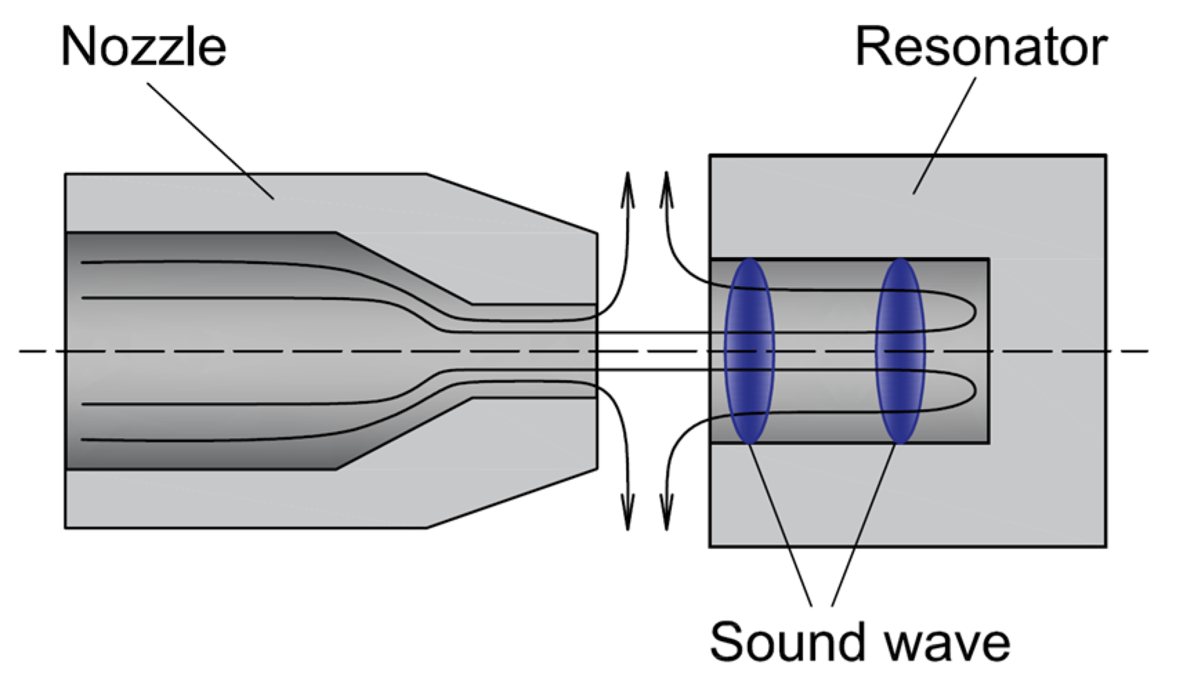
Figure 1. Ultrasound generator design and operating principle.
Energies 17 04975 g001
Figure 2. The design of a spark arrester with the design features of an ultrasound generator.
Energies 17 04975 g002
Figure 3. An example of a spark gap arrester in a disassembled state.
Energies 17 04975 g003
Figure 4. Diagrams of the high-voltage test bench: (a) block diagram; (b) electrical diagram.
Energies 17 04975 g004
Figure 5. The geometry of the spark gap arrester: (a) highlighted area with initial non-zero conductivity; (b) with a mesh for calculations.
Energies 17 04975 g005
Figure 6. Block diagram of a high-voltage test bench.
Energies 17 04975 g006
Figure 7. Comparison of experimental and calculated time dependencies of voltage (a) and current (b) on the spark gap arrester under study.
Energies 17 04975 g007
Figure 8. Temperature distributions at various points in time: (a) 1 μs; (b) 4 μs; (c) 12 μs; (d) 24 μs; (e) 36 μs; (f) 60 μs; (g) 90 μs; (h) 175 μs; (i) 400 μs; (j) 1 ms; (k) 3 ms; (l) 5 ms.
Energies 17 04975 g008
Figure 9. Time dependencies of pressure: (a) comparison of time dependencies of pressure at points 1 and 2 obtained by numerical simulations; (b) the location of points 1 and 2 inside the spark gap arrester.
Energies 17 04975 g009
Figure 10. Comparison of time dependencies of pressure in the spark gap region for the spark gap arrester designs with and without a nozzle and resonator.
Energies 17 04975 g010
Disclaimer/Publisher’s Note: The statements, opinions and data contained in all publications are solely those of the individual author(s) and contributor(s) and not of MDPI and/or the editor(s). MDPI and/or the editor(s) disclaim responsibility for any injury to people or property resulting from any ideas, methods, instructions or products referred to in the content.