Article

Position Servo Control of Electromotive Valve Driven by Centralized Winding LATM Using a Kalman Filter Based Load Observer

by
Yi Yang
1,
Xin Cheng
1,2,* and
Rougang Zhou
3,4,5,*
1
School of Information Engineering, Wuhan University of Technology, Wuhan 430070, China
2
School of Mechanical & Electronic Engineering, Wuhan University of Technology, Wuhan 430070, China
3
School of Mechanical Engineering, Hangzhou Dianzi University, Hangzhou 310018, China
4
Wenzhou Institute of Hangzhou Dianzi University, Wenzhou 325013, China
5
Mstar Technologies, Inc., Hangzhou 310012, China
*
Authors to whom correspondence should be addressed.
Energies 2024, 17(17), 4515; https://doi.org/10.3390/en17174515
Submission received: 14 June 2024 / Revised: 13 July 2024 / Accepted: 17 July 2024 / Published: 9 September 2024
(This article belongs to the Section F1: Electrical Power System)

Abstract

The exhaust gas recirculation (EGR) valve plays an important role in improving engine fuel economy and reducing emissions. In order to improve the positioning accuracy and robustness of the EGR valve under uncertain dynamics and external disturbances, this paper proposes a positioning servo system design for an electromotive (EM) EGR valve based on the Kalman filter. Taking a novel valve driven by a central winding limited angle torque motor (LATM) as the object, we have fully considered the influence of the motor rotor position and load current, as well as the magnetic field saturation and cogging effect, improved the existing LTAM model, and derived accurate torque expression. The parameter uncertainty of the above internal model and the external stochastic disturbance were unified as “total disturbance”, and a Kalman filter-based observer was designed for disturbance estimations and real-time feed-forward compensation. Furthermore, using non-contact magnetic angle measurements to obtain accurate valve position information, a position control model with real-time response and high accuracy was established. Numerous simulated and experimental data show that in the presence of ± 25% plant model parameter fluctuations and random shock-type disturbances, the servo system scheme proposed in this paper achieves a maximum position deviation of 0.3 mm, a repeatability of positioning accuracy after disturbances of 0.01 mm, and a disturbance recovery time of not more than 250 ms. In addition, the above performance is insensitive to the duration of the disturbance, which demonstrates the strong robustness, high accuracy, and excellent dynamic response capability of the proposed design.

1. Introduction

NOx (nitrogen oxide) and its secondary pollutants can form photochemical smog in the atmosphere and can also be harmful to the human nervous system [1]. As a result, engine manufacturers are seeking to improve fuel efficiency and drivability to meet environmental regulations and customer demand. A large number of studies have been conducted to reduce vehicle NOx emissions, encompassing charge air intercooling technology [2], catalytic reduction systems [3], particulate filters [4], oxidation catalysts [5], exhaust gas recirculation [6], etc. The EGR process has been of great interest in recent studies, as in [7], and has been shown to have a potential impact on emissions and fuel economy.
The EGR valve is the key component in controlling the in-cylinder gas state [8]. By controlling the valve opening, a portion of the exhaust gas is directed to re-enter the combustion chamber of an automotive engine, reducing the combustion rate and the maximum combustion temperature, thereby significantly reducing NOx emissions [1,6,7,8]. The EGR rate represents the ratio of the amount of exhaust gas to the total amount of intake air entering the cylinder [9]. To achieve the optimum balance between engine performance and emissions, the EGR rate in the system must be dynamically adjusted according to the load and temperature of the engine. Previous EM EGR valves have only been motorized and are simply actuators driven by a motor or solenoid [10], with their controllers integrated into the engine controller. The engine controller has to consider controlling a waste gate valve, an EGR valve, and a throttle valve, as shown in Figure 1 [11].
Advanced control algorithms may be an effective approach to reduce the number of tuning parameters in the control system. Using automated dynamometer tests, the authors of [12] introduced response surface methods, model-based calibration, and optimization algorithms to realize an efficient calibration process. Studies have been carried out on model predictive control (MPC), which addresses the control problem of optimizing multiple input–multiple output (MIMO) systems under multiple constraints. Kang and co-workers performed an engine hardware simulation based on the torque controller proposed in [13] and a virtual test bench in [14]. A discrete time identification model was proposed by Odachi and co-workers to overcome the problems associated with the computational load of the MPC algorithm [15]. However, the above method couples the uncertainty control problem of the EGR valve itself with the multi-parameter control of the engine conditions, which can lead to an extremely complex multi-parameter tuning process. In addition, it is difficult to achieve good EGR rates under a wide range of transient operating conditions by simply debugging experimental parameters at multiple operating points under steady state conditions [16].
An effective solution to the above problems is to establish a position servo system, i.e., an upper system which outputs the reference position while the servo system controls the object to achieve the reference position. However, in practical applications, the EGR valves suffer from uncertainties [17], such as dynamic and static friction due to the motion unit repeated switching phenomenon and road surface-induced vehicle vibration problems. The application conditions of the above disturbances are complex, making it difficult to accurately model the disturbance characteristics and introducing obvious uncertainties. Another unfavorable factor is the slowly changing plant dynamics due to carbon, pollution and exhaust corrosion, and other application environmental factors [10,18]. Therefore, the goal of EGR valve control at this stage is to achieve higher valve position control accuracy and dynamic response without overshoot in the presence of the above uncertain disturbances [19]. H. J. Kim et al. [19] proposed an EGR position control scheme to improve the position response at a low control frequency. The friction compensation and friction observer approaches for the unknown load torque were proposed in [20] and [21], respectively. The authors of [22] introduced the artificial electric field algorithm (AEFA) to optimize the fuzzy PID to achieve high-precision attitude control of small satellites. However, the PID control law is error-driven, and the accuracy and responsiveness of the controller depend on the parameter tuning, which is prone to mismatched uncertainty in the case of slowly varying plant dynamics. In addition, the short travel of the EGR valve makes it more difficult for the position control method, based on trajectory planning [23], to achieve a relatively reliable real-time response.
Modern control approaches have also achieved some research results for dynamic complex EGR systems. Mahdi Z. and co-workers [24] adopt an improved Gaussian process to identify such dynamics; their obtained model was then considered in the design of an optimal model-based control strategy. A linear and real-time adaptive control law [25,26] was found to be effective to keep the system stable in a variable-parameter magnetic levitation system, when the load mass of the maglev system varies greatly. To compensate for the effect of velocity lag, a nonlinear internal mode controller for linear valve control was designed [27]. In [28], a multi-reference online model predictive control (MPC) approach was designed based on a scheduling scheme considering the NOx tracking performance under uncertainties. To avoid the complex obstacle of modelling, the authors of [29] designed a model error compensator to compensate for the effect of model uncertainty caused by unmodeled nonlinear and dynamic factors. S. Lee and co-workers [30] predicted the EGR rate under transient and real driving emission conditions by building different models using a deep learning method. State observers are typically used to estimate system states that cannot be measured directly by sensors [31,32,33]. The authors of [34] proposed an improved linear active disturbance rejection control (LADRC) system with a fast-tracking differentiator (FTD) to manage the transient process of input signals. However, the above algorithms are computationally expensive in practical engineering applications, it is difficult to tune their parameters, and they place high requirements on the microcontroller platform and require accurate system parameters. In summary, the above methods have made some progress in similar applications but, considering the presence of slowly varying plant dynamics in the system under real vehicle conditions [35] and the fact that the complexity of stochastic disturbance transfer laws makes them difficult to model, the practical performance of model-based observer methods will be limited by the accuracy of the model.
In order to achieve positioning accuracy and robustness of EM valves under the above conditions, this paper proposes a servo system design in which internal model uncertainty and external disturbance are unified into the whole system disturbance and an observer is designed for disturbance estimations and online feed-forward compensation. The main contributions of this study are as follows.
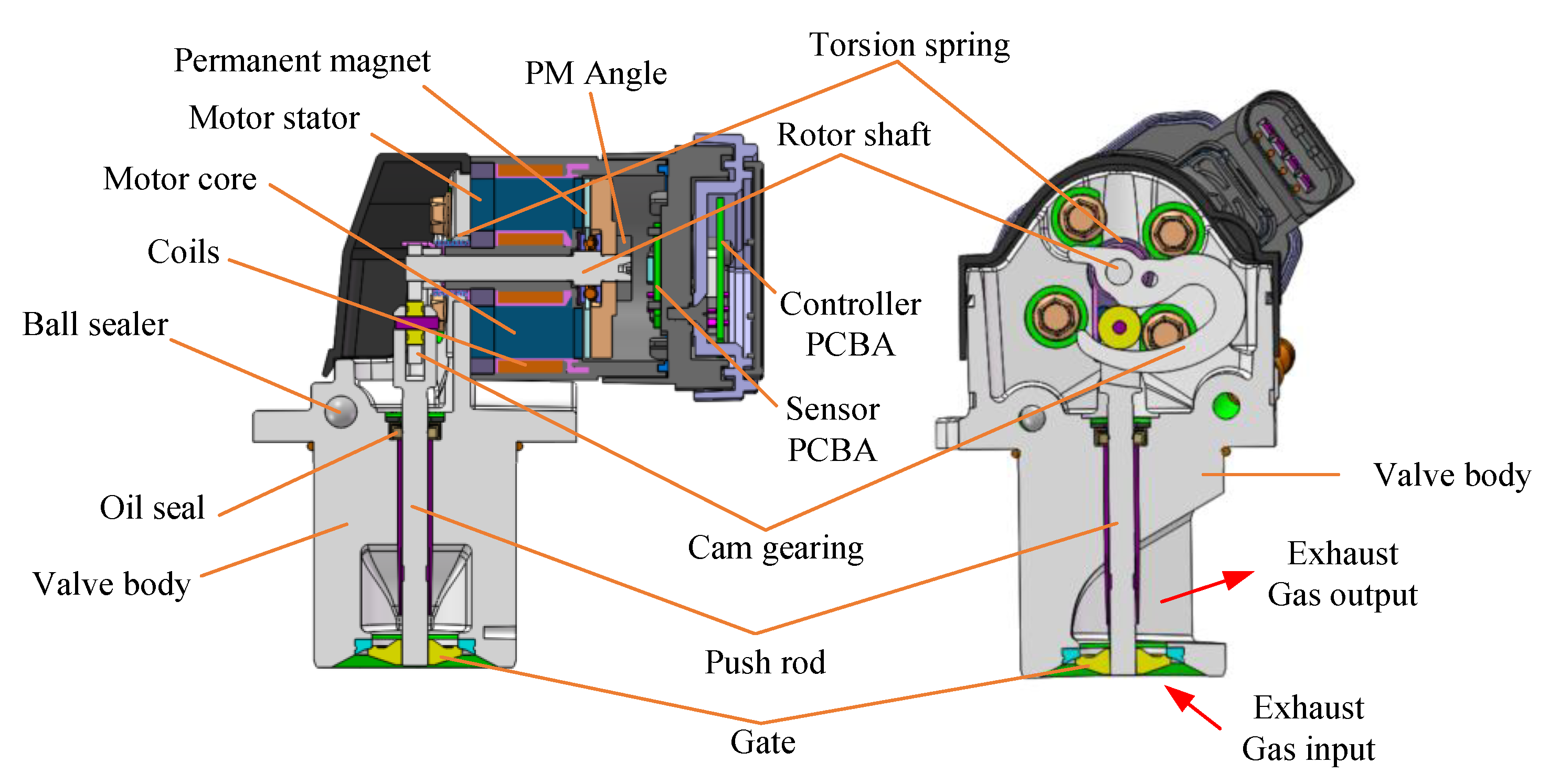
  • A new motorized valve structure driven by LATM is described in detail. We have fully considered the influence of motor rotor position and load current, magnetic field saturation and the cogging effect, improved the existing cogging structure LTAM model, and derived an accurate torque expression.
  • Through accurate system dynamics modelling, simulation verification, and definition of the available angular range, the uncertainty in the original system is transformed into unknown but bounded uncertainty.
  • The proposed approach presents an EM EGR valve servo system scheme with a dual closed-loop position and current, which achieves excellent positional accuracy and strong robustness to random shock-type disturbances through high-precision non-contact angle measurements, on-line load estimations, and feed-forward compensation.
The rest of this paper is organized as follows. Section 2 presents the structure and model. Section 3 presents the design of the servo system based on Kalman filtering, while Section 4 discusses the hardware configuration. Section 5 presents the experimental validation, and Section 6 gives the conclusions.

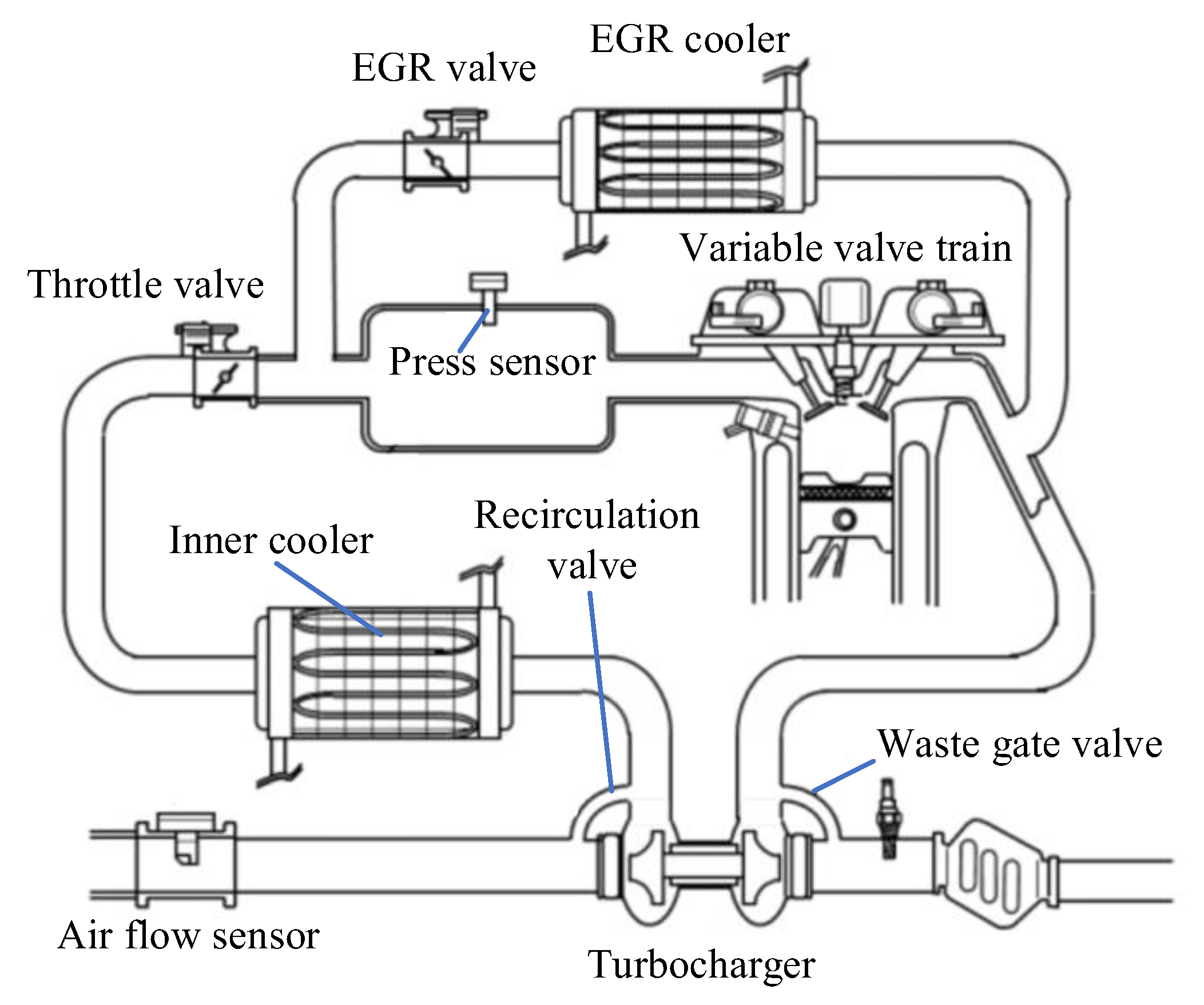
2. Structure and Modeling

2.1. Introduction of Structure

The object discussed is shown in Figure 2. The stator windings create a controllable electromagnetic field when a current is applied, which creates an electromagnetic torque to drive the shaft to rotate. Further details of the structural analysis can be found in another paper [35] from our group.

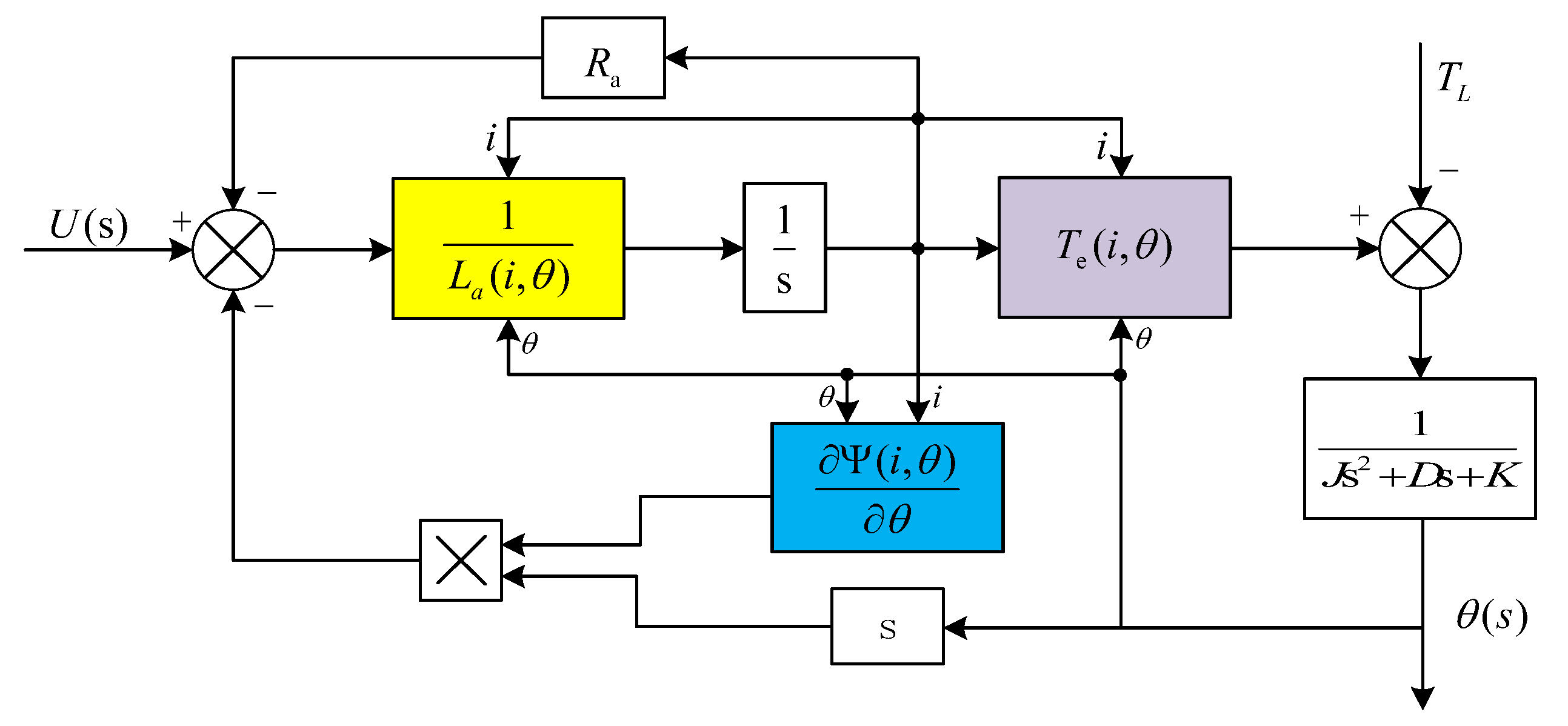
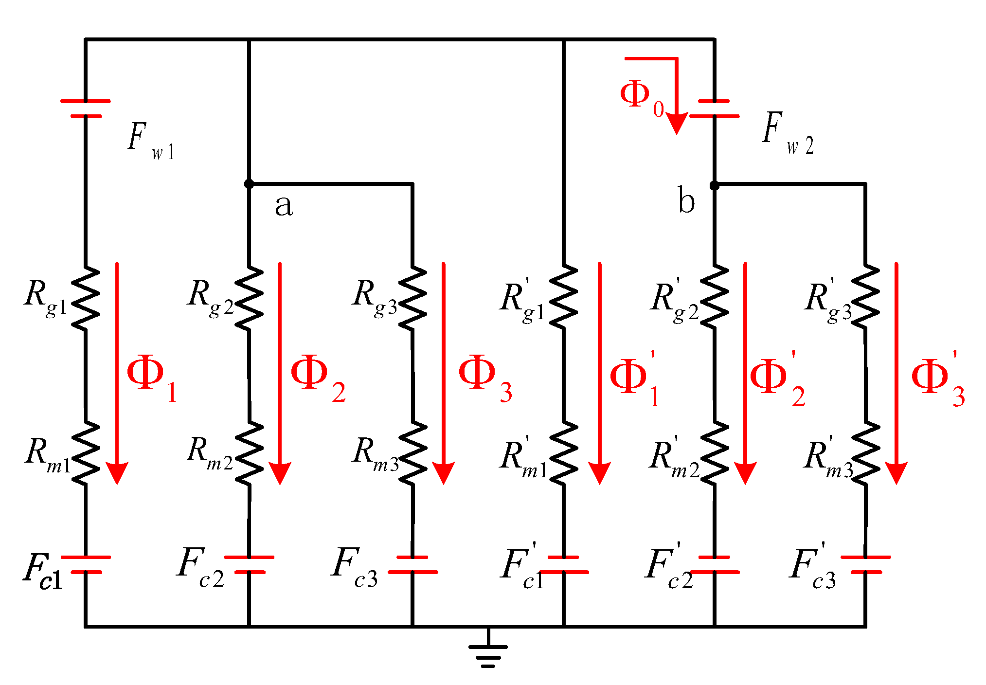
2.2. Centralized Winding LTAM Modeling

By considering the influence of rotor position change and the current magnitude on the electromagnetic parameters, we establish an accurate model of the centralized winding LATM. Equation (1) is the voltage equation considering magnetic field saturation.
u = i a R + d Ψ ( i , θ ) d t
where, u, i, R and ᴪ represent the voltage of the power, the current, the resistor of the coils, and the magnetic linkage in the air gap, respectively. By expanding Equation (1), we have
u = i a R + Ψ ( i , θ ) i d i d t + Ψ ( i , θ ) θ d θ d t
where θ represents the angle of the rotor. Inductance L a i , θ   can be derived with the help of finite element tools, so Equation (2) can be further simplified as:
u = i a R + L a ( i , θ ) d i d t + Ψ ( i , θ ) θ d θ d t
The following equation is the torque equation considering magnetic field saturation. The effect of cogging torque is included in the electromagnetic torque term, T e ( i , θ ) , as in Equation (4). J, D, and K represent the moment of inertia of the shaft and the damping and elasticity coefficients, while the TL represents the load torque.
T e ( i , θ ) = J d 2 θ d t 2 + D d θ d t + K θ + T L T e ( i , θ ) = 0 i Ψ ( i , θ ) θ d i
Combining Equations (1) to (4), an improved mathematical model of the centralized winding LATM can be derived, as shown in Figure 3.

2.3. Analytical Expression of the Electromagnetic Torque

In order to reduce the uncertainty of the LATM model and to obtain an accurate expression for the electromagnetic torque, the permanent magnets and air gap reluctance in the centralized winding LATM are divided into three parts according to the tooth shape, and their parameters with the dimensions that will be used are identified, as shown in Figure 4.
According to Figure 4, using the similarity between the magnetic field and electric field in mathematical formulas, the nodal voltage method in the circuit is extended to the magnetic circuit, and the magnetic kinetic potential and magnetic flux density at each point are found. Additionally, the equivalent magnetic circuit model of the centralized winding LATM is established, as shown in Figure 5. Node a and node b represent the symmetrical regions in the stator core, respectively.
The nodal magnetic potential and nodal flux equations corresponding to node a and node b are given by Equations (5) to (7). Due to the magnetic force potential F w between a and b, we introduce magnetic flux   Φ 0 to ensure that the equations have a solution.
F a + F w = F b
1 R g 3 + R m 2 + 1 R g 2 + R m 2 F b Φ 0 = F c 3 R g 3 + R m 3 F c 2 R g 2 + R m 2
1 R g 1 + R m 1 + 1 R g 2 + R m 2 + 1 R g 3 + R m 3 + 1 R g 1 + R m 1 F a + Φ 0 = F c 1 + F w R g 1 + R m 1 + F c 2 R g 2 + R m 2 F c 3 R g 3 + R m 3 F c 1 R g 1 + R m 1
where   R g 1 , R g 2 , R g 3 , R g 1 , R g 2 ,   a n d   R g 3 represent the equivalent magnetoresistance in the corresponding air gap, F a , F b represent the nodal magnetic potential, F c 1 , F c 2 , F c 3 ,   F c 1 , F c 2 ,   a n d   F c 3 represent the corresponding magnetic kinetic potential of the permanent magnet, and F w , F w represent the magnetic potential of the winding, respectively.
From Equations (8) to (9), it can be seen that
F a = F w 1 R g 1 + R m 1 1 R g 3 + R m 3 1 R g 2 + R m 2 2 R g 1 + R m 1 + 2 R g 2 + R m 2 + 2 R g 3 + R m 3
F b = F a + F w
The magnetic potential of the permanent magnet and the winding is calculated as:
F c 1 = F c 2 = F c 3 = F c 1 = F c 2 = F c 3 = h m H c
F w = F w = N I
where H c , h m ,   N , and I represent the coercivity of permanent magnets, the thickness of the equivalent permanent magnet in the direction of magnetization, the armature winding turns, and the value of the winding current, respectively. Since the core losses are neglected, when the rotor is in the position shown in Figure 4, the expression for each reluctance is
R m 1 = R m 1 = 1 μ 0 μ r r 1 r 2 1 l π 4 r d r = 4 π μ 0 μ r l ln r 2 r 1
R m 2 = R m 2 = 1 μ 0 μ r r 1 r 2 1 l ( π 4 θ ) r d r = 1 ( π 4 θ ) μ 0 μ r l ln r 2 r 1
R m 3 = R m 3 = 1 μ 0 μ r r 1 r 2 1 l θ r d r = 1 θ μ 0 μ r l ln r 2 r 1
R g 1 = R g 1 = 1 μ 0 r 2 r 3 1 l π 4 r d r = 4 π μ 0 l ln r 3 r 2
R g 2 = R g 2 = 1 μ 0 r 2 r 3 1 l ( π 4 θ ) r d r = 1 π 4 θ μ 0 l ln r 3 r 2
R g 3 = R g 3 = 1 μ 0 r 2 r 3 1 l θ r d r = 4 θ μ 0 l ln r 3 r 2
where μ 0   , μ r , and l   r e p r e s e n t air permeability, t h e relative permeability of permanent magnets, and the axial length of the permanent magnet.
From Equations (14) to (17), it can be concluded that both the permanent magnet and the air gap reluctance are related to the rotor position. If the flux direction is labelled according to Figure 4, the flux in each branch can be expressed by Equations (18) to (23).
Φ 1 = F a F w F c 1 R g 1 + R m 1
Φ 2 = F a F c 2 R g 2 + R m 2
Φ 3 = F a + F c 3 R g 3 + R m 3
Φ 1 = F a + F c 1 R g 1 + R m 1
Φ 2 = F b + F c 2 R g 2 + R m 2
Φ 3 = F b F c 3 R g 3 + R m 3
If the motor operates in the linear interval, the magnetic co-energy between the air gap and the permanent magnet can be expressed as in Equation (24).
W f = F Φ 2
The expression for the electromagnetic torque of the centralized winding of the LATM can be obtained by combining Equations (8) to (24).
T e = p W f θ = 2 p μ 0 μ r H c h m N I l ln r 2 / r 1 + μ r ln r 3 / r 2
where p   is the number of LATM pole pairs. From Equation (25), the electromagnetic torque is proportional to the structural parameters such as the number of pole pairs, the thickness of the equivalent permanent magnet magnetization direction, and the number of coils turns.

3. Position Servo Control System Using a Kalman-Filter Based Load Observer

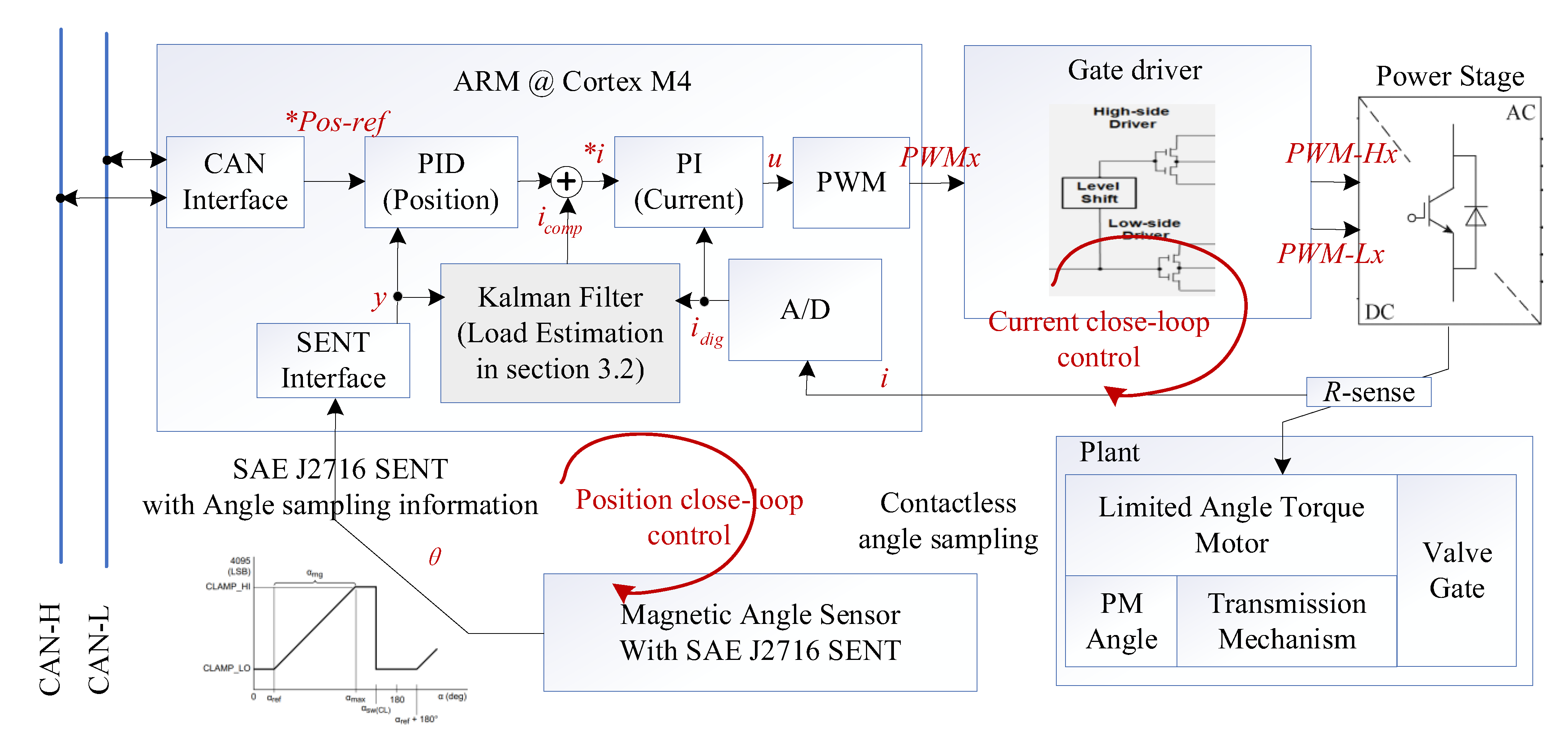
3.1. Position Servo System Structure

As shown in Figure 6, the servo system has a dual closed-loop structure. A Kalman filter-based load estimation was designed to compensate the observed load to the current control closed loop. θ represents the rotor angle, and i, i_err, i*, and ia represent the output of the position controller, the close-loop error, the desired current, and the actual current, respectively.

3.2. Kalman Filter Based Load Observer

We propose a Kalman filtering-based approach based on the state-space model of the system, using the minimum variance as the prediction criterion, the estimated value at the previous sampling moment, and the observed value at the current moment to correct the estimated value of the load by the Kalman gain to obtain the theoretically optimal load estimation. The system is described as
x ( k ) = F x ( k 1 ) + B u ( k 1 ) + w ( k 1 ) y ( k ) = C x ( k ) + v ( k )
where F, B, and C represent the state transfer matrix, the control matrix, and the observation matrix, respectively. w and v are denoted as system noise and measurement noise, respectively, and both are white noise conforming to a normal distribution with zero mean. The covariance matrix of the noise is defined as
Q = cov ( w ) = E { w w T } R = cov ( v ) = E { v v T }
where Q and R are system noise and the covariance matrix and the measurement noise covariance matrix, respectively.
The iterative process of the Kalman filtering algorithm is as follows:
  • Calculate the a priori estimates of the state variables and the a priori estimates of the covariance matrix, as follows.
    x ^ ( k ) = F x ^ ( k 1 ) + G u ( k 1 ) P ^ ( k ) = F P ^ ( k 1 ) F T + Q
  • Calculate the Kalman gain.
    K ( k ) = P ^ ( k ) H T H P ^ ( k ) H T + R
  • The state estimation is corrected based on the measurements, and the optimal estimate of the state variable is calculated, also known as the a posteriori estimate, which is the optimized output of the algorithm.
    x ^ ( k ) = x ^ ( k ) + K ( k ) [ y ( k ) H x ^ ( k ) ]
  • Calculate the posterior covariance matrix.
    P ^ ( k ) = [ I K ( k ) H ] P ^ ( k )
The Kalman optimization algorithm is based on the state space expression of the system. In Section 2.2 and Section 2.3, we have established the mathematical model of the LATM, which can be rewritten for the mechanical equations of motion of the motor of Equation (4) in the form of state equations. The state variables are selected as Equation (32).
x = [ ω θ T L ] T
The input variable is
u = [ T e ]
Then the state equation of the observer is
ω ˙ θ ˙ T ˙ L = D J K J 1 J 1 0 0 0 0 0 ω θ T L + 1 J 0 0 T e
The output variable is selected as
y = θ
Rewriting Equations (34) and (35) into matrix form yields
x ˙ = A x + G u y = C x
where C = [ 0 , 1 , 0 ] T . Expanding Equation (36) into discrete iterative form using the first-order Taylor’s formula, and also treating the error generated by the approximation process as system noise, yields:
x ( k ) = x ( k 1 ) + [ A x ( k 1 ) ] T S = ( 1 + A T S ) x ( k 1 ) + G u ( k 1 ) T S
Define:
F = I + A T S = ( 1 D J ) T S K T S J T S J T S T S 0 0 0 T S B = G T S = [ T S / J 0 0 ] T
The system state equations and measurement equations in the discrete domain can be obtained as
x ( k ) = F x ( k 1 ) + B u ( k 1 ) + w ( k ) y ( k ) = C x ( k ) + v ( k )
By substituting Equation (39) into Equations (28)–(31), the Kalman filter-based load torque observation is realized. The observed motor output angle is treated as the position feedback of the system, and the observed torque value is used for feed-forward compensation, as shown in Figure 6. K T is the EM torque coefficient, while k is the compensation coefficient; its value should be the reciprocal of the K T .

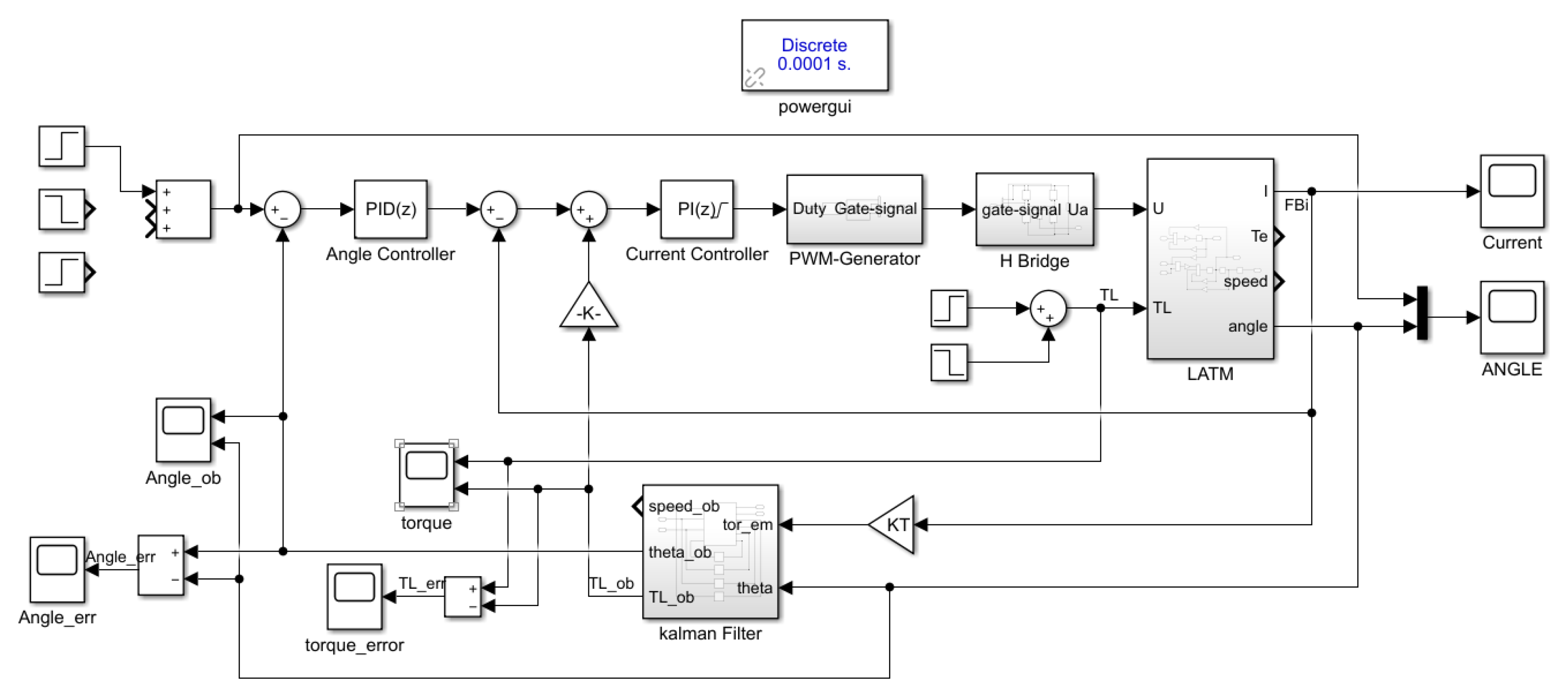
3.3. Simulation Verification

The simulation model of the servo system, realized in Matlab 2022b, is shown in Figure 7. The LATM model is derived from Equation (40), i.e., the improved model in Figure 3.
The inputs to the Kalman filter module are the electromagnetic torque and rotor position calculated from the winding currents, the outputs are the estimated load torque, and the rotor position and rotational speed. The values of the motor parameters are shown in Table 1.
U ( s ) = R I a ( s ) + L a I a ( s ) s + E ( s ) E ( s ) = K e θ ( s ) s T e ( s ) = T L ( s ) = J θ ( s ) s 2 + D θ ( s ) s + K θ ( s ) T e ( s ) = K T I a ( s )
The above parameters are measured at room temperature and may vary at higher temperatures. In practice, the temperature of the exhaust gas from a car engine is around 800–900 degrees Celsius when it passes through the three-way catalytic converter and the radiator and enters the EGR valve. However, by precisely controlling the coolant temperature, the actual operating temperature of the EGR valve is maintained within the range of 110–130 degrees Celsius. High temperature grease is used in the system design to avoid an increase of mechanical friction at high temperatures. The main effects of high temperatures are the demagnetization of the permanent magnets and fluctuations in the inductance and resistance values, which affect the accuracy of the specific feed-forward compensation values, so the control parameters should be calibrated based on the operating temperatures.
In addition, the values of Q and   R , which reflect the effects of modelling and measurement errors, must be taken into account. Accurate observations of the load torque require accurate motor model parameters and information about the complete state of the motor. Considering that noise terms w and v are assumed to affect the estimation results in different cases, their corresponding noise covariance matrices Q and   R should be set as diagonal matrices; their final values are shown in Equation (41).
Q = 0.1 0 0 0 0.01 0 0 0 3 R = 10
The simulation process was set up as follows. The reference position was set to 0.6 rad, and the motor was started with no load. After stabilization, a constant load of 0.4 N · m was added abruptly at 0.6 s, and then the load was reduced abruptly by 0.4 N · m at 1 s.
From the simulation result in Figure 8a, it can be seen that when the load was changed abruptly, the estimated value of the load had a certain hysteresis, but it converged to the real value within 15 ms, and then basically yielded unbiased estimations. The reason for the above phenomenon is that the Kalman filter is a time-domain recursive algorithm, which is jointly influenced by all past states, and there is a certain delay. From Figure 8b,c it can be seen that the controller could effectively suppress the effect of sudden load changes and keep the rotor in the reference position; additionally, the position error was close to 0 after less than 100 ms of adjustment time. Figure 8d shows the rotor position response under the same controller parameters, which shows that the feed-forward compensation could better compensate for the influence of the opposing load torque, improve the anti-interference characteristics of the control system, and improve the position control performance when the load torque was disturbed.

4. Position Servo System Implementation

In a typical application, the EM valve is a node on the CAN bus, which is a part of the intelligent actuators controlled by the on-board network. In accordance with the controller structure in Figure 6, a CAN bus-based position servo system was designed for the electronically controlled EGR valve in Figure 9.
The servo system contains an ARM-based controller, gate driver, power stage, sampling resistor (for current measurement), controlled motor and drive structure, and non-contact magnetic angle sensor (for position measurements). The servo system obtains reference position *Pos-ref, while the SENT interface obtains valve position y according to the transmission model, and the position controller outputs the desired controlled current according to the positional error, which, in turn, creates the desired electromagnetic torque for positional adjustment.
The design of the current control closed-loop improved the response speed and accuracy of the controlled current, i.e., the actual current information was obtained through the sampling resistor, the current controller calculated the current error and output the desired control command u output, which, through the PWM module as well as the pre-driver unit, generated the actual current ia.

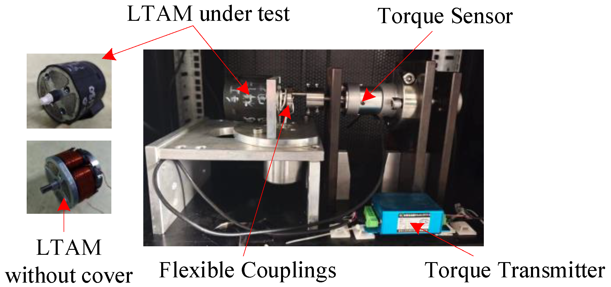
5. Experimental Verification

5.1. Plant Dynamics

Figure 10 shows that the experimental platform I. A tightening and positioning mechanism was designed to realize the electromagnetic torque output of the LATM motor under different stator and rotor angles.
A flexible coupling was designed to transfer the EM torque to the sensor. The range of the torque sensor was 0–0.5 N*m, and the resolution was 0.2% F.S. The torque transmitter converted the output signal of the sensor into a voltage signal, and the torque value was observed by an oscilloscope.
As shown in Figure 11a, when the stator-rotor angle was fixed, the electronic output EM torque and current were proportional to each other, which corresponded to the conclusion of Equation (25). The EM torque coefficient K T , defined as the ratio between the torque and the load current, could be calculated by the red line, and the value under a stator-rotor deviation of 45 degrees in Figure 11a was set to 0.1264 N*m/A.
Figure 11b shows the EM torque coefficient at each angle. It can be seen that the EM torque was affected by the cogging torque and friction. The selected effective working angle was 15–75 degrees. The model in Table 1 selected the EM torque coefficient with a stator-rotor deviation of 45 degrees (theoretically at this time, the cogging torque was 0 N*m), but there was a parameter fluctuation of maximum ± 25% in the range of its application interval, and there were obvious uncertainty dynamics.

5.2. Positioning Accuracy

Figure 12 shows experimental platform II. A displacement sensor was selected to validate the accuracy performance of the proposed method by obtaining the position under different valve opening commands. Keens IL-S-065 has a repeatable accuracy of 2 um and a maximum detection distance of 75 mm.
To verify the performance of the method in this paper in terms of disturbance rejection, we added a small cylinder (with a bore of 10 mm and a thrust disturbance of 1.57 kgN under 0.2 Mpa pressure) to provide a shock-type disturbance.
Figure 13 shows the valve positioning errors of different prototypes under different valve opening requirements. It can be seen that the maximum error of the method in this paper did not exceed 0.02 mm over the entire effective stroke range, and its positioning accuracy was 0.23% F.S. Compared with the previous LADRC-based control strategy developed by our group [35], its valve control accuracy showed better performance. It can be seen that the method in this paper is not sensitive to the fluctuation of the electromagnetic torque coefficient parameter of the maximum 25% in plant dynamics and has a good ability to suppress the internal model uncertainty.

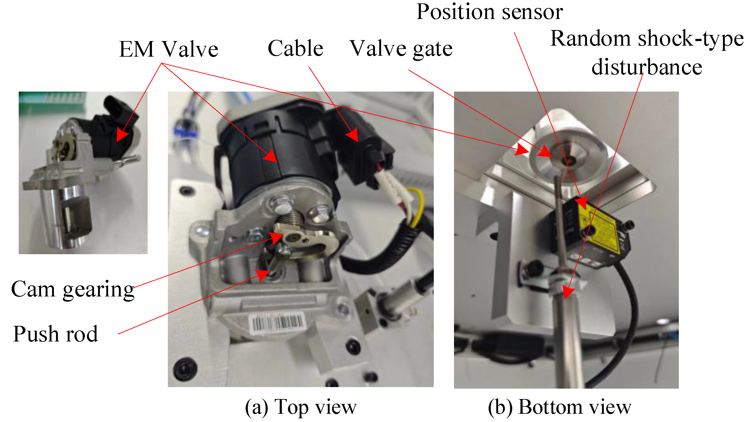
5.3. Verification of Shock-Type Disturbance Rejection

Figure 14a shows the gate trajectory under a 1.57 KgN shock-type disturbance with a duration of 300 ms. The maximum position error under the disturbance was about 0.1 mm and the recovery time was around 150 ms. The valve position error was much larger and the recovery time was longer, as shown in Figure 14b.
After the shock-type disturbance occurred, the servo system responded quickly to suppress the influence of the disturbance and return to the reference target position after the disturbance had disappeared. This proves that the system designed in this paper has a strong ability to suppress external shock disturbances.
The disturbance suppression performance of the system was further analyzed under different disturbance forces and durations. In Figure 15, it can be seen that as the disturbance air pressure increased, both the system positioning error and the recovery time increased. Additionally, the displacement under the effect of 0.6 Mpa@4.71 KgN disturbance reached a deviation of about 0.65 mm, and the recovery time was about 250 ms, i.e., the trajectory shown in Figure 13b. However, the errors after the end of the disturbances were all at the same level, i.e., between about 0.01–0.02 mm, and did not increase with the increase of the disturbances force.
As can be seen from Figure 16, the above parameters were insensitive to the disturbance duration and all remained at similar values when the disturbance duration varied from 0.5–1.2 s. The positioning accuracy also remained in a stable range of 0.01–0.02 mm.

6. Conclusions

In this paper, a new type of EM EGR valve driven by a central winding type LTAM was taken as the object, and a position servo system design scheme based on Kalman filter load observation is proposed, which solves the problem of valve positioning accuracy and robustness under the influence of uncertain dynamics and external random disturbances. A simulation and the experimental results demonstrate that:
(1)
The servo system scheme proposed in this paper can compensate for the influence of external shock-type disturbances in real time through effective load observation and realize better valve positioning accuracy, dynamic response capabilities, and robustness.
(2)
The proposed Kalman filter-based load observation method can converge to the real load value within 15 ms and then realize unbiased estimations.
(3)
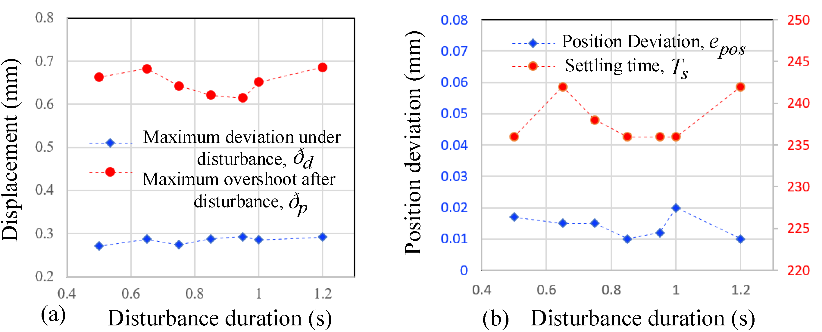
The proposed method showed a good real-time response and the ability to suppress external disturbances, and after the disappearance of the disturbance, the EM valve could be quickly restored to the reference position, with a maximum position offset of not more than 0.3 mm, a repeatable positioning error of not more than 0.002 mm after the disappearance of the disturbance, and a disturbance recovery time of not more than 250 ms. Additionally, consistent results were obtained in multiple repetitions of measurements, which demonstrates the validity and repeatability of this method.
(4)
The proposed method was not sensitive to the duration of the disturbance, and the values of position error, overshoot, disturbance recovery time, and other parameters caused by the disturbance of 0.5–1.2 s duration were almost at the same level.
(5)
Future work will be carried out in two directions: (1) Study of the influence of high temperatures on the dynamics of the plant under the actual application conditions, which could effectively improve the adaptability of the observer in different applications and further improve its observation accuracy; and (2) The failure mechanism of the observer and the constraints of the applied parameters, which could further improve the effectiveness of the application of the methods in this paper.

Author Contributions

Methodology, X.C.; validation, Y.Y.; writing—original draft preparation, Y.Y.; writing—review and editing, X.C.; supervision, R.Z.; project administration, R.Z. All authors have read and agreed to the published version of the manuscript.

Funding

This work was funded by the National Natural Science Foundation of China under Grant No. 52275065.

Data Availability Statement

The original contributions presented in the study are included in the article, further inquiries can be directed to the corresponding author.

Acknowledgments

The authors would like to thank Fu C. of the Wuhan University of Technology for helpful experiment validation.

Conflicts of Interest

Author Rougang Zhou was employed by the company Mstar Technologies, Inc. The remaining authors declare that the research was conducted in the absence of any commercial or financial relationships that could be construed as a potential conflict of interest.

References

  1. Wang, Y.; Su, S.; Lai, Y.; Luo, W.; Hou, P.; Lyu, T.; Ge, Y. China 6 EGR gasoline vehicles without a GPF may struggle to meet the potential SPN10 limit. Environ. Int. 2023, 181, 108306. [Google Scholar] [CrossRef]
  2. Ibrahim, A.; Bari, S. An experimental investigation on the use of EGR in a supercharged natural gas SI engine. Fuel 2010, 89, 1721–1730. [Google Scholar] [CrossRef]
  3. Li, X.; Liu, X.; Tang, H.; Zou, Y.; Cen, W.; Zhu, T. Simultaneously accomplishing selective catalytic reduction of NO and catalytic oxidation of CO in a catalyst coupling system. Fuel 2024, 360, 130616. [Google Scholar] [CrossRef]
  4. Guan, B.; Zhan, R.; Lin, H.; Huang, Z. Review of the state-of-the-art of exhaust particulate filter technology in internal combustion engines. J. Environ. Manag. 2015, 154, 225–258. [Google Scholar] [CrossRef]
  5. Dubien, C.; Schweich, D.; Mabilon, G.; Martin, B.; Prigent, M. Three-way catalytic converter modelling: Fast-and slow-oxidizing hydrocarbons, inhibiting species, and steam-reforming reaction. Chem. Eng. Sci. 1998, 53, 471–481. [Google Scholar] [CrossRef]
  6. Wei, H.; Zhu, T.; Shu, G.; Tan, L.; Wang, Y. Gasoline engine exhaust gas recirculation–a review. Appl. Energy 2012, 99, 534–544. [Google Scholar] [CrossRef]
  7. Panni, F.S.; Waschl, H.; Alberer, D.; Zaccarian, L. Position regulation of an EGR valve using reset control with adaptive feedforward. IEEE Trans. Control Syst. Technol. 2014, 22, 2424–2431. [Google Scholar] [CrossRef]
  8. Hirata, M.; Hayashi, T.; Takahashi, M.; Yamasaki, Y.; Kaneko, S. A nonlinear feedforward controller design taking account of dynamics of turbocharger and manifolds for diesel engine air-path system. IFAC Pap. OnLine 2019, 52, 341–346. [Google Scholar] [CrossRef]
  9. Yang, C.; Wang, B.; Wang, H.; Hu, D.; Duan, B.; Wang, Y. The effect of changing EGR rate on engine performance under different ammonia/methanol ratios. J. Energy Inst. 2024, 113, 101546. [Google Scholar] [CrossRef]
  10. Gutfrind, C.; Dufour, L.; Liebart, V.; Vannier, J.C. An approach to the prototyping of an optimized limited stroke actuator to drive a low pressure exhaust gas recirculation valve. Sensors 2016, 16, 735. [Google Scholar] [CrossRef]
  11. Suzuki, K. Feasibility Study on Model Predictive Control for an EGR-Air Path System in a Turbocharged SI Engine. IFAC Pap. OnLine 2021, 54, 27–32. [Google Scholar] [CrossRef]
  12. Guerrier, M.; Cawsey, P. The development of model based methodologies for gasoline IC engine calibration. SAE Tech. Pap. 2004, 1, 1466. [Google Scholar] [CrossRef]
  13. Ohtsuka, T. A continuation/GMRES method for fast computation of nonlinear receding horizon control. Automatica 2004, 40, 563–574. [Google Scholar] [CrossRef]
  14. Kang, M.; Shen, T. Receding horizon online optimization for torque control of gasoline engines. ISA Trans. 2016, 65, 371–383. [Google Scholar] [CrossRef] [PubMed]
  15. Odachi, K.; Oyama, H.; Yamakita, M. Nonlinear model predictive control of SI engine using discrete time identification model. In Proceedings of the 2015 54th Annual Conference of the Society of Instrument and Control Engineers of Japan (SICE), Hangzhou, China, 28–30 July 2015; pp. 1305–1310. [Google Scholar] [CrossRef]
  16. Shiraishi, T.; Hirata, M.; Nishida, R.; Suzuki, M.; Muto, M.; Fujii, T.; Hikita, T. Nonlinear feedforward controller design for air-path system with transport dynamics of external EGR system. IFAC Pap. OnLine 2021, 54, 1–6. [Google Scholar] [CrossRef]
  17. Pashaei, S.; Badamchizadeh, M. A new fractional-order sliding mode controller via a nonlinear disturbance observer for a class of dynamical systems with mismatched disturbances. ISA Trans. 2016, 63, 39–48. [Google Scholar] [CrossRef]
  18. Williams, R.; Cook, S.; Woodall, K.; Clayton, C.; Gee, M.; Mulqueen, S.; Reid, J.; Rimmer, J.; Ross, A. Development of an engine test to rate the EGR deposit formation propensity of fuels in light-duty diesel engines. SAE Int. J. Adv. Curr. Pract. Mobil. 2020, 3, 337–348. [Google Scholar] [CrossRef]
  19. Kim, H.J.; Son, Y.D.; Kim, J.M. Improved Position Control for an EGR Valve System with Low Control Frequency. Energies 2020, 13, 457. [Google Scholar] [CrossRef]
  20. Bhuiyan, H.; Lee, J.H. Low cost position controller for exhaust gas recirculation valve system. Energies 2018, 11, 2171. [Google Scholar] [CrossRef]
  21. Ashok, B.; Denis, A.S.; Ramesh, K.C. An Integrated Pedal Follower and Torque Based Approach for Electronic Throttle Control in a Motorcycle Engine. Eng. J. 2017, 21, 63–80. [Google Scholar] [CrossRef]
  22. Zhang, Z.; Li, Y. An AEFA-Based Optimum Design of Fuzzy PID Controller for Attitude Control Flywheel with BLDC Motor. Aerospace 2022, 9, 789. [Google Scholar] [CrossRef]
  23. Heo, H.J.; Son, Y.; Kim, J.M. A Trapezoidal Velocity Profile Generator for Position Control Using a Feedback Strategy. Energies 2019, 12, 1222. [Google Scholar] [CrossRef]
  24. Zarghami, M.; Hosseinnia, S.H.; Babazadeh, M. Optimal control of egr system in gasoline engine based on gaussian process. IFAC Pap. OnLine 2017, 50, 3750–3755. [Google Scholar] [CrossRef]
  25. Zhang, L. Hopf Bifurcation and Vibration Control for a Thrust Magnetic Bearing with Variable Load Mass. Sensors 2018, 18, 2212. [Google Scholar] [CrossRef] [PubMed]
  26. Zhang, Z.; Li, X. Real-Time Adaptive Control of a Magnetic Levitation System with a Large Range of Load Disturbance. Sensors 2018, 18, 1512. [Google Scholar] [CrossRef]
  27. Cheng, W.; Tan, Y.; Lu, Y.; Dong, R.; Tan, Q.; Chen, X. Nonlinear internal model control of EGR valve. In Proceedings of the 2019 12th Asian Control Conference (ASCC), Kitakyushu, Japan, 9–12 June 2019; pp. 1233–1236. [Google Scholar]
  28. Waschl, H.; Alberer, D.; del Re, L. Multi Reference Model Predictive EGR-Valve Control for Diesel Engines. In Proceedings of the International Federation of Automatic Control, Rueil-Malmaison, France, 23–25 October 2012; pp. 474–481. [Google Scholar] [CrossRef]
  29. Tan, Y.; Cheng, W.; Dong, R.; Tan, Q.; Cao, Q. Online optimizing positioning control with model error compensator for LEGRV system. IEEE-ASME Trans. Mechatron. 2020, 25, 594–603. [Google Scholar] [CrossRef]
  30. Lee, S.; Lee, Y.; Lee, Y.; Kim, M.; Shin, S.; Park, J.; Min, K. EGR prediction of diesel engines in steady-state conditions using deep learning method. Int. J. Automot. Technol. 2020, 21, 571–578. [Google Scholar] [CrossRef]
  31. Rajaei, N. Model Based Control of Exhaust Gas Recirculation Valves and Estimation of Spring Torque. Master’s Thesis, University of Windsor, Windsor, ON, Canada, 2010. [Google Scholar]
  32. Gao, J.; Feng, K.; Wang, Y.; Wu, Y.; Chen, H. Design, implementation and experimental verification of a compensator-based triple-step model reference controller for an automotive electronic throttle. Control Eng. Prac. 2020, 100, 104447. [Google Scholar] [CrossRef]
  33. Li, Y.; Yang, B.; Zheng, T.; Li, Y.; Cui, M.; Peeta, S. Extended-state-observer-based double-loop integral sliding-mode control of electronic throttle valve. IEEE Trans. Intell. Transp. Syst. 2015, 16, 2501–2510. [Google Scholar] [CrossRef]
  34. Yu, T.; Zhang, Z.; Li, Y.; Zhao, W.; Zhang, J. Improved active disturbance rejection controller for rotor system of magnetic levitation turbomachinery. Electron. Res. Arch. 2023, 31, 1570–1586. [Google Scholar] [CrossRef]
  35. Cheng, X.; Yin, J.; Li, X.; Zhou, R.; Fu, C. Design and Implementation of a linear active disturbance rejection control-based position servo control system of an electromotive valve for exhaust gas recirculation. Sensors 2024, 24, 1393. [Google Scholar] [CrossRef] [PubMed]
Figure 1. Schematic of a turbocharged engine system with an EGR system.
Energies 17 04515 g001
Figure 2. Structure of the electromotive EGR valve.
Energies 17 04515 g002
Figure 3. Block diagram of the improved model of the centralized winding LATM.
Energies 17 04515 g003
Figure 4. Centralized winding LATM parameters and dimensional identification.
Energies 17 04515 g004
Figure 5. Equivalent magnetic circuit model of the centralized winding LATM.
Energies 17 04515 g005
Figure 6. Block diagram of position servo system based on load torque observation and feed-forward compensation.
Energies 17 04515 g006
Figure 7. Simulation platform of Kalman filter-based feed forward compensation.
Energies 17 04515 g007
Figure 8. Simulation results of load torque observation. (a) Estimated and actual values of load; (b) Position response under sudden load change; (c) Controlled current during adjustment; (d) Position control results with and without feed-forward compensation.
Energies 17 04515 g008
Figure 9. Block diagram of position servo system for the EM valve.
Energies 17 04515 g009
Figure 10. Experimental platform I.
Energies 17 04515 g010
Figure 11. LTAM output electromagnetic torque characteristics, (a) relationship between electromagnetic torque and motor current for a stator-rotor relative angle of 45 degrees; (b) electromagnetic torque coefficients for rotor angles of 10–100 degrees.
Energies 17 04515 g011
Figure 12. Experimental platform II.
Energies 17 04515 g012
Figure 13. Valve gate position accuracy. (a) Position accuracy. (b) Comparison of maximum error in this paper and adapted with permission from Ref. [35].
Energies 17 04515 g013
Figure 14. Verification of shock-type disturbance rejection. (a) Gate trajectory under a 1.57 KgN shock-type disturbance with a duration of 300 ms. (b) Gate trajectory under a 4.71 KgN shock-type disturbance with a duration of 750 ms. Maximum deviation under disturbance, ðd. Maximum overshoot after disturbance, ðp. Settling time, Ts. Shock-type disturbance duration, Td.
Energies 17 04515 g014
Figure 15. Disturbance rejection performance of the system under different disturbing cylinder pressures. (a) Maximum deviation under disturbance. (b) Maximum overshoot after disturbance. (c) Positioning error after disturbance. (d) Settling time after disturbance.
Energies 17 04515 g015
Figure 16. Disturbance rejection performance for different disturbance durations. (a) Maximum deviation under disturbance and maximum overshoot after disturbance. (b) Position deviation and settling time after disturbance.
Energies 17 04515 g016
Table 1. Motor parameters in simulation.
SymbolParameterValueUnit
RResistance of stator winding3.6Ω
L a Equivalent inductance of winding32mH
JRotor moment of inertia0.002 k g · m 2
DViscous damping coefficient0.0024 N · m · s / r a d
KTorsion spring stiffness0.12 N · m / r a d
K T Electromagnetic torque coefficient0.126 N · m / A
K e Back electromagnetic force coefficient0.126 V · s / r a d
Disclaimer/Publisher’s Note: The statements, opinions and data contained in all publications are solely those of the individual author(s) and contributor(s) and not of MDPI and/or the editor(s). MDPI and/or the editor(s) disclaim responsibility for any injury to people or property resulting from any ideas, methods, instructions or products referred to in the content.

