Article

Consensus-Based Model Predictive Control for Active Power and Voltage Regulation in Active Distribution Networks

Department of Electrical and Information Engineering, University of Cassino and Southern Lazio, Via G. Di Biasio 43, 03043 Cassino, Italy
*
Author to whom correspondence should be addressed.
These authors contributed equally to this work.
Energies 2024, 17(17), 4490; https://doi.org/10.3390/en17174490
Submission received: 26 July 2024 / Revised: 27 August 2024 / Accepted: 29 August 2024 / Published: 6 September 2024

Abstract

:
In this paper, a consensus-based model predictive control (Cb-MPC) scheme is proposed to control the active power and voltage at all nodes in grid-connected active distribution networks (ADNs) with multiple distributed energy resources (DERs). The proposed design methodology is based on a multiple-input multiple-output (MIMO) model of an ADN which accounts for both the internal and external interactions among the control loops of the DERs. To achieve the control objective, each DER unit is equipped with a controller–observer system. In particular, the observer implements the consensus algorithm to estimate the collective system state by exchanging data only with its neighbors. The scope of the controller is to solve the MPC optimal problem based on its collective state estimate, and, due to the presence of an integral term in the control action, it is robust against any unknown scenarios of the ADN, which are represented by uncertainty in the model parameters. The results of numerical simulations validate the effectiveness of the proposed method in the presence of unknown changes in the operating conditions of the ADN and of communication using a sample and hold function.

1. Introduction

Electric distribution systems are undergoing significant changes under the strong push of environmental policies [1]. In fact, the exploitation of renewable energy sources (RESs) introduces small-sized distributed generators (DGs) that are connected to a distribution network (DN). DGs have a significant impact on the operation of a DN, especially on the voltage profiles, but they could be turned into an opportunity if adequately controlled [2]. In particular, DGs that exploit RESs can be equipped with energy storage systems (ESSs), which introduce flexibility in the active power control. Moreover, the reactive power injected by the power electronic devices that interface both the DGs and ESSs with the DN represents an additional source of flexibility. For this reason, during the evolution toward the smart distribution grids of the future, DGs and ESSs represent distributed energy resources (DERs) that can be controlled to simultaneously achieve two objectives: optimally exploiting the RESs and contributing to the voltage control in the active distribution networks (ADNs).
An ADN is an interconnected dynamic system, such as a multi-robot swarm, multi-agents, etc. The control of these systems, which overlaps with several research communities, is characterized by different definitions and a variety of approaches ranging from rigorous mathematical analysis to trial-and-error experimental study or the emulation-by-observation of natural phenomena. An overview can be found, among other things, in [3]. It turns out that most of the convergence properties of a network of interconnected dynamic systems are regulated by the so-called graph theory. A detailed analysis is out of the scope of this paper, but a short tutorial can be found in [4,5].
For the voltage control in an ADN, paper [6] presented one of the first studies that explores the potential of model predictive control (MPC). Subsequently, several papers investigated the use of MPC for voltage control using different flexible resources such as DERs, including DGs, ESSs, and electric vehicles (EVs), while also providing quality service to customers, the reduction of power losses, and the active power curtailment of photovoltaic (PV) output. Paper [7] proposes a combined wind farm controller based on MPC that accounts for the impact of active power on voltage variations due to the low X / R ratio of wind farms. Paper [8] proposes an MPC-based decentralized control strategy for DERs that are regulated with local Q V control curves to mitigate voltage fluctuations. The MPC technique is also employed in paper [9] to coordinate voltage regulation and the state of the charge of EVs. Paper [10] addresses the problem of EV charging stations based on PV/ESSs using MPC. In [11], the use of a local control scheme to enhance voltage quality is combined with a centralized controller that solves a multi-time-step-constrained optimization, inspired by MPC, to adjust the reactive power set point sent to each DER. In [12], a decentralized distributed model predictive control scheme is presented which employs the charging/discharging flexibility of EVs to provide voltage regulation, avoiding the active power curtailment of PVs. Paper [13] proposes MPC-based decentralized robust control of hybrid distribution transformers for voltage regulation in ADNs. In [14], MPC is used to control the frequency of micro-grid systems.
A different approach to the voltage control problem in ADNs is based on the use of centralized control schemes. Paper [15] proposes a centralized approach to coordinate DERs and OLTC, while paper [16] presents a PI control unit with a corrective control unit based on MPC. Paper [17] develops a control strategy-based coordinated MPC that considers the fluctuations of stochastic renewable sources, as well as weather conditions. An MPC-based technique is presented in [18], which proposes the utilization of flexible resources such as ESSs to provide voltage control and quality service to customers by employing an on-line power flow calculation. Finally, in paper [19], a centralized MPC scheme is proposed, including constraints that should guarantee robustness with respect to the uncertainties in RESs.
Concerning the architecture to be adopted in the voltage control, the large extent of ADNs and the increasing number of DERs make centralized control architecture difficult to implement in real cases; consequently, decentralized approaches are typically preferred [20,21]. The design of the local controller of any DER is a key problem because DERs interact through the ADN, causing undesired coupling whose effects may deteriorate the control performance [22]. Therefore, the distributed voltage control scheme has attracted the attention of smart grid control communities because introducing communication among the local controllers of DERs enables a cooperative approach and improves the stability of the operation of the controllers [23]. In [24], a consensus-based distributed control scheme is proposed to regulate the voltages and minimize the active power curtailment. The distributed approach proposed in [25] uses an off-line calculation of the sensitivity coefficients under the assumption that they undergo limited variations. However, it was seen that a large percentage variation of such coefficients can be expected over the wide range of different operating conditions that are present in ADNs. A distributed MPC approach using Q V control is proposed in [26] to reduce voltage violations, utilizing the ability of smart buildings to provide reactive power. Paper [27] presents a distributed MPC for the optimal management and operation of distributed wind and solar energy generation in ADNs.
A basic characteristic of distributed control is that a DER is not required to communicate with all the other DERs in the network but only with its neighbors. To keep this key feature, the present paper proposes a Cb-MPC (consensus-based model predictive control) algorithm to control the active power and voltage at each node where a DER is connected. From a modeling perspective, traditional control solutions for voltage regulation typically model the ADN as a collection of decoupled subsystems where the effects of neighboring subsystems are simply treated as measurable disturbances [28]. However, ADNs cannot be considered as a set of fully independent subsystems because DERs are coupled through the grid. Ignoring this strong physical coupling when designing distributed control systems could render the control ineffective. For this reason, this paper proposes a square MIMO model of the ADN that accounts for both internal and external interactions among the control loops of any DER. The approach developed in this paper is inspired by [29], where a decentralized controller–observer scheme for a multi-robot system is presented. The key idea is to develop, for each network’s node, an observer of the collective system’s state along with an appropriate controller. The observer is updated using only information from the node itself and from its neighbors; the controller is designed to achieve global or collective control objectives. The controller is based on an MPC approach which is gaining increasing interest within the control community due to its design flexibility and the ability to include constraints into the control design [30]. Additionally, an internal local observer loop must be designed by using standard linear dynamic systems theory [31].
Unlike papers [25,32], which estimate the sensitivity coefficients, and papers [11,26,33], which do not provide any discussion, the proposed algorithm uses the off-line calculation of sensitivity coefficients to model the grid. The advantage is that a detailed formulation and mathematical calculations of the power flow equations, as required in [18], are not necessary. The proposed algorithm effectively mitigates the effects of unpredictable variations in these sensitivity coefficients on the controlled outputs by incorporating an integral action into the state vector of the collective dynamic model.
The main contributions of this paper are summarized as follows:
  • A Cb-MPC is adopted for active power and voltage regulation at the connection node of each DER;
  • An MIMO model of the ADN is employed in the design to account for the effects of both internal and external interactions among DERs;
  • An integral action MPC is implemented to counteract the effects of uncertainties in modeling parameters;
  • Communication among DERs is incorporated into the numerical validation through a proper sample and hold function.
Table 1 summarizes the features of the proposed method in comparison with some other methods for DER control in the literature. Specifically, the proposed method features the following:
  • Compared to [12,16,19,25], the proposed method adopts an accurate DER model that accounts for the dynamic response of the closed-loop controls of the DER current components along the d-q axis. This model enables accurate estimation of the state variables through local observers;
  • Compared to [12,28,34], the proposed method uses a comprehensive ADN model to account for all the interactions among the active power and voltage controllers of all the DERs;
  • Compared to [12,16,19,28], the proposed method adopts a consensus-based algorithm that ensures convergence of the distributed algorithm to the optimal solution;
  • Compared to [28], the proposed method employs an MPC algorithm capable of effectively handling current saturations and interactions among different DERs;
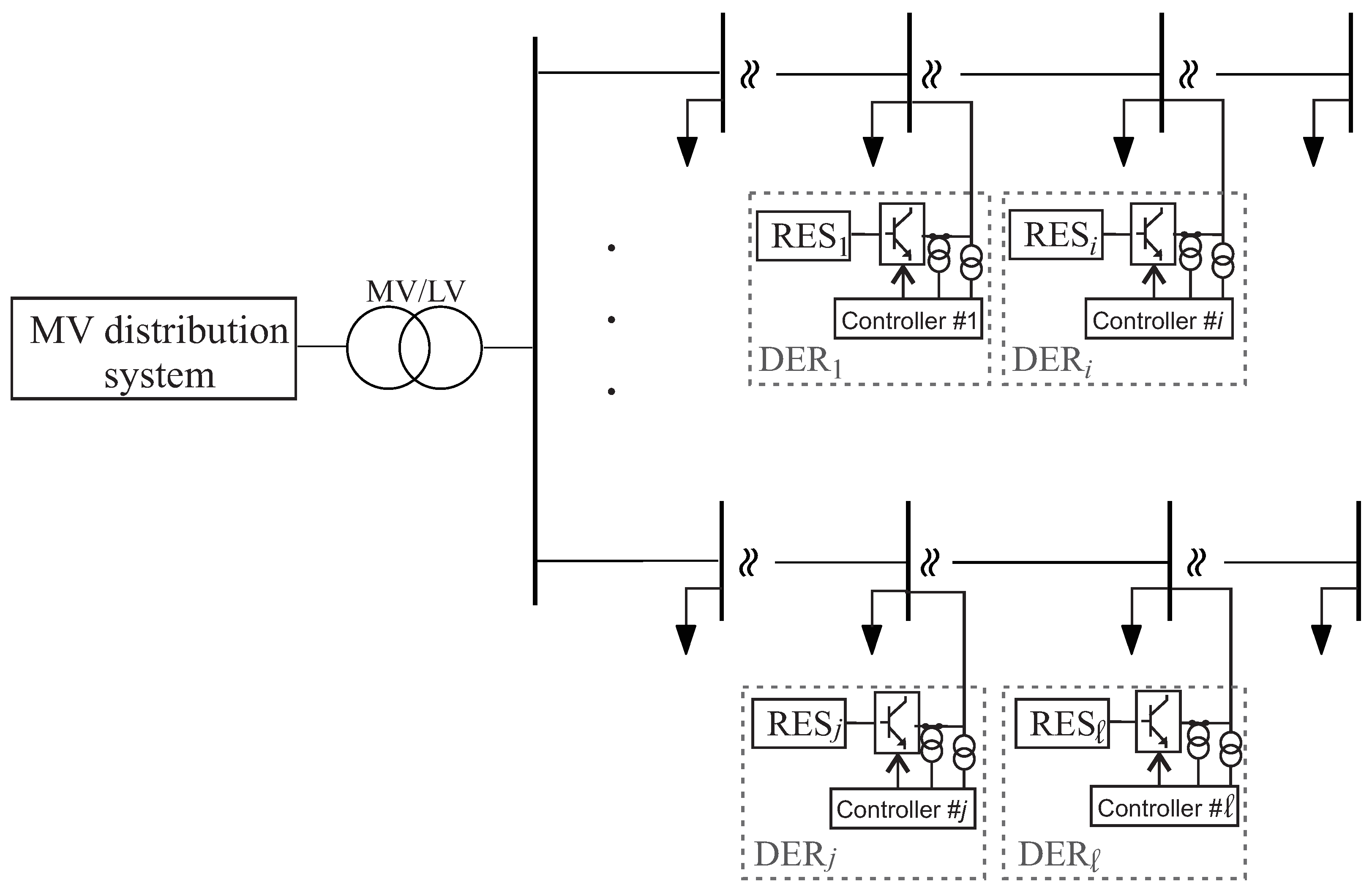
  • Compared to [12,16,19,25], the proposed method incorporates an integral action that guarantees null steady-state errors even in the presence of uncertainties in the model parameters;
  • Compared to [16,19], the proposed method uses a distributed rather than a centralized architecture, resulting in lower communication requirements.
The rest of the paper is organized as follows: Section 2 and Section 3 present, respectively, the model and the description of the proposed solution. Section 4 reports the numerical validation for an ADN with six DERs, and, finally, Section 5 draws the conclusions.

2. Model

The generic structure of an ADN is illustrated in Figure 1. The distribution grid, depicted at low voltage (LV), is supplied by a node at a higher voltage level, depicted at medium voltage (MV), where the voltage amplitude and phase are assigned (slack bus). The substation transformer feeds a busbar from which various feeders extend in a radial configuration. Each feeder consists of lines connecting nodes where loads and/or DERs are connected. The total number of DERs in the network is assumed to be . In the following, the model of the DERs and their interactions through the distribution network are described, with all electrical quantities expressed in per unit (p.u.) with a common unit base.
Regarding the DERs, the most common configuration includes a renewable energy system (RES), which may also be equipped with an energy storage system (ESS), and is connected to the network through a current-controlled voltage source converter (CCVSC). For the j-th DER, the CCVSC can be modeled by the transfer functions of the current closed control loops in the dq coordinate frame, which is synchronized with the network nodal voltage phasor v j so that v j , q = 0 . Assuming the current reference values i j , d , r e f and i j , q , r e f as inputs and the measured currents i j , d and i j , q injected by the DER into the network as outputs, the following TITO model is adopted [20]:
i j , d i j , q T = G j ( s ) i j , d , r e f i j , q , r e f T
with
G j ( s ) = 1 1 + s τ j d k j 1 s ( 1 + s τ j 1 ) ( 1 + s τ j 2 ) k j 2 s ( 1 + s τ j 3 ) ( 1 + s τ j 4 ) 1 1 + s τ j q
where τ j d , τ j q , τ j 1 , τ j 2 , τ j 3 , τ j 4 are appropriate time constants, and k j 1 , k j 2 are gain parameters.
A state-space realization of model (1) is trivially obtained by applying the Gilbert technique, refer to [31] for details, resulting in the following model representation:
x ˙ j = A j x j + B j i j , d , r e f i j , q , r e f = A j x j + B j u j with x j R 6 i j , d i j , q = i j = C ˜ j x j
with
A j = diag 1 τ j d 1 τ j q 1 τ j 1 1 τ j 2 1 τ j 3 1 τ j 4 B j = 1 / τ j d 0 0 1 / τ j q 0 k j 1 , n τ j 1 ( τ j 1 τ j 2 ) 0 k j 1 τ j 2 ( τ j 2 τ j 1 ) k j 2 τ j 3 ( τ j 3 τ j 4 ) 0 k j 2 τ j 4 ( τ j 4 τ j 3 ) 0 C ˜ j = 1 0 1 1 0 0 0 1 0 0 1 1
Model (3) in the case of DERs takes the following form:
x ˙ = A x + B u i = C ˜ x
where x = x 1 T x 2 T x l T T R 6 l , u = u 1 T u 2 T u l T T R 2 l and
A = diag A 1 A 2 A l R 6 l × 6 l B = B 1 O 6 × 2 O 6 × 2 O 6 × 2 B 2 O 6 × 2 O 6 × 2 O 6 × 2 B l R 6 l × 2 l C ˜ = C ˜ 1 O 2 × 6 O 2 × 6 O 2 × 6 C ˜ 2 O 2 × 6 O 2 × 6 O 2 × 6 C ˜ l R 2 l × 6 l
where O n × m represents an n × m null matrix.
The active and reactive powers ( p j , q j ) injected by the j-th DER are
p j = v j i j , d q j = v j i j , q
which are rewritten through linearization around an initial operating point as follows:
Δ p j = v j 0 Δ i j , d + i j , d 0 Δ v j   Δ q j = v j 0 Δ i j , q + i j , q 0 Δ v j
where the superscript " 0 " denotes the value of a variable at the initial operating point, and the prefix “ Δ ” indicates the variation of a variable with respect to its initial value. Model (6) can be written in compact form as
Δ [ p j q j ] T = v j 0 Δ i j + i j 0 Δ v j
with i j = [ i j , d i j , q ] T . The models (7) related to all the DERs are assembled in the following matrix form:
Δ F = V 0 Δ i + I 0 Δ v
with
F = [ p 1 q 1 p l q l ] T i = [ i 1 T i l T ] T v = [ v 1 v l ] T V 0 = diag [ v j 0 I 2 ]
where I n is the ( n × n ) identity matrix, I 0 is a ( 2 l × l ) matrix adequately composed of vectors i j 0 for j = 1 , , l , and V 0 is a ( 2 l × 2 l ) matrix adequately composed of the elements v j 0 for j = 1 , , l .
Since this paper focuses on controlling the active power injections and voltage amplitudes, the distribution system operation can be represented using phasor quantities. The most commonly adopted model for radial configurations is based on the non-linear DistFlow equations. However, approximate linear models are more suitable for DER control design. By employing the constrained Jacobian-based method proposed in [35] and extended in [36], the following model in variational form with respect to the initial operating point of the network can be written:
2 diag [ v j 0 ] Δ v = Γ Δ F
where Γ is a l × 2 l matrix of known sensitivity coefficients. Substituting (8) for Δ F in (9) and solving in Δ v yields
Δ v = T v Δ i
where matrix T v I R l × 2 l is evaluated as
T v = 2 diag [ v j 0 ] Γ I 0 1 Γ V 0
Substituting (10) for Δ v in (8) yields
Δ p = T p Δ i
with p = [ p 1 p l ] T . Matrix T p I R l × 2 l is obtained by extracting the even rows of the matrix V 0 + I 0 T v . Eventually, (10) and (11) are assembled in matrix form as
Δ y = T Δ i
where y = [ p 1 v 1 p l v l ] T R 2 l is the vector of the controlled outputs and matrix T I R 2 l × 2 l is obtained by alternating the rows of T p and T v . It is important to point out that matrix T is evaluated in a given operating condition of the ADN. If T is evaluated in the initial operating point with null currents and powers injected by DERs into the ADN, that is, i 0 = 0 and p = 0 , model (12) becomes
y = y 0 + T i
where y 0 = 0 v m 1 0 0 v m 1 0 0 v m l 0 T represents a voltage bias.
Finally, the comprehensive MIMO model of the ADN can be obtained by combining models (4) and (13). Specifically, substituting i = C ˜ x from (4) into (13) yields
x ˙ = A x + B u y = C x + y 0
with C = T C ˜ .
It is worth noting that the resulting model (14) accounts for two types of interactions. The former interaction is internal to each DER; it is related to the mutual coupling between the current components along the d–q axes and represented by the off-diagonal elements of matrix G j ( s ) in (2). The latter interaction is external to each DER; it is related to the effects of the closed control loops of the other DERs through the distribution grid and represented by matrix T.

3. Proposed Solution

The proposed solution is based on a distributed controller–observer scheme, represented in Figure 2. Each DER implements three tasks:
  • A local deterministic observer that evaluates the local state x ^ j R 6 in (3), according to [20];
  • A distributed consensus algorithm that evaluates the collective state x R 6 l in (14);
  • A constrained MPC [30] that uses the local estimate of the collective state to determine the command input to the CCVSC.
The MPC output is a collective vector of dimension 2 l , but the j-th DER implements only the two values related to its own current components, disregarding the other values.
As is typical for observer–controller schemes [31], the three tasks are designed to exhibit different bandwidths; the local observer presents a larger bandwidth than the distributed consensus task, which, in turn, presents a larger bandwidth than the MPC. The three tasks are described in the following subsections.

3.1. Local Observer

For each DER, a deterministic observer is implemented which is based on the discretization of the DER dynamic system model [20]. Using the Euler approximation of the derivative with the increments
x ˙ j = x j ( k + 1 ) x j ( k ) T
the DER model (3) is discretized, yielding
x j ( k + 1 ) = I 6 + T A j x j ( k ) + T B j u j ( k ) = A j x j ( k ) + B j u j ( k ) y j ( k ) = C ˜ j x j ( k )
where the approximation is valid provided that the sampling time T is small enough with respect to the time constants of the dynamic model.
Since the model (15) results are observable, it is possible to design the following deterministic (Luenberger) observer:
x ^ j ( k + 1 ) = A j x ^ j ( k ) + B j u j ( k ) + K o y j ( k ) y ^ j ( k ) .
The choice of the gain matrix K o R 6 × 2 determines the placement of the closed-loop eigenvalues of the new dynamic matrix on the error  A j K o C j . It can easily be computed through the Ackermann formula.

3.2. Consensus

Following the steps outlined in [29], each DER estimates the states of all the other DERs by exchanging information solely with its neighbors. This process is referred to as consensus in the literature and results in a distributed estimation of the collective state. The cited paper demonstrates the convergence of the controller–observer scheme under the assumptions of connected undirected graphs as well as directed balanced and strongly connected topologies. Each DER must know the structure of the other controllers to emulate it during the consensus process. In this paper, each DER implements the same constrained MPC, thereby satisfying this assumption.
Let the vector   i x ^ R 6 l be defined as the collective state computed by the i-th DER and let Π i be the ( 6 l × 6 l ) selection matrix:
Π i = diag { O 6 × 6 I 6 × 6 i th node O 6 × 6 } .
The following equality holds:
i = 1 l Π i = I 6 l × 6 l .
The collective state is estimated by the i-th DER ( i = 1 , , l ) through the following observer [29]:
  i x ^ ˙ = A   i x ^ + B   i u ^ + k o j N i   j x ^   i x ^ + Π i x   i x ^ ,
where k o > 0 is a scalar gain to be properly selected and
  i u ^ ( t ,   i x ^ ) = u 1 ( t ,   i x ^ ) u 2 ( t ,   i x ^ ) u l ( t ,   i x ^ ) R 6 l
represents the estimate of the collective input available to the i-th DER. It is worth noting that, to implement the observer (19), each DER uses only local information because Π i selects the i-th component of the collective state x, i.e., the sole state of the i-th DER. In addition, the exchange of the estimates is performed with the neighbors. Since the local state is not available as a measure, the output of the local observer is used, and (19) is rewritten as
  i x ^ ˙ = A   i x ^ + B   i u ^ + k o j N i   j x ^   i x ^ + Π i x ^ i   i x ^
where the vector x ^ i consists of the local observer estimates, with the remaining elements set to zero for the sake of equation compactness. These zero elements are effectively filtered out by the selection matrix  Π i .

3.3. Control Loop

The controller is designed using the discretized collective dynamic model (14). Due to the uncertainty in the matrix T, an integral action is incorporated. With this aim, the state vector is extended:
z = x x e
where
x e ( k + 1 ) = x e ( k ) + y d y ( k ) R 2 l
and the collective dynamic model (14) becomes
z ( k + 1 ) = A O C I z ( k ) + B O u ( k ) + 0 y d y ( k ) = C O z ( k )
which must be verified for controllability.
The MPC is designed to minimize the scalar functional
J ( u ( · ) ) = k = 0 N 1 z T ( k ) Q z ( k ) + u T ( k ) S u ( k ) + z T ( N ) P z ( N )
where N is the number of horizon samples and Q = Q T O R 8 l × 8 l , S = S T O R 2 l × 2 l , and P = P T O R 8 l × 8 l are weight matrices for the transient error, the control effort, and the steady-state error, respectively. Since the sole controlled variable is the output, a proper choice for Q is
Q = C T Q C with Q O
where C filters out the state components and keeps the only integral of the output errors as the control objective to be driven to zero.
The MPC can easily cope with the following constraints:
s . t . u min u ( k ) u max k = 0 , , N 1 y min y ( k ) y max k = 1 , , N
In conclusion, each DER solves the MPC problem by resorting to its local estimate of the collective state   i x ^ and evaluates a collective command input which is only partially used, extracting its own two components.

3.4. Time Constant Constraints

The choice of the sampling times of the three tasks requires satisfying a bandwidth separation constraint
T < < τ o l < < τ o g < < τ c
where τ o g and τ o l are the time constants of the local and collective observers, respectively, and τ c is the equivalent time constant of the MPC. It is worth noticing that an unconstrained MPC for linear systems is actually an LQR which can be implemented with a constant control gain matrix, thus assigning the closed-loop control eigenvalues. On the basis of this consideration, the choice of τ c assumes reasonable complexity.

3.5. DER Communication Constraints

Each DER executes its algorithm locally at the sampling time T while exchanging data with neighboring DERs at each T c o m m using a sample and hold function.

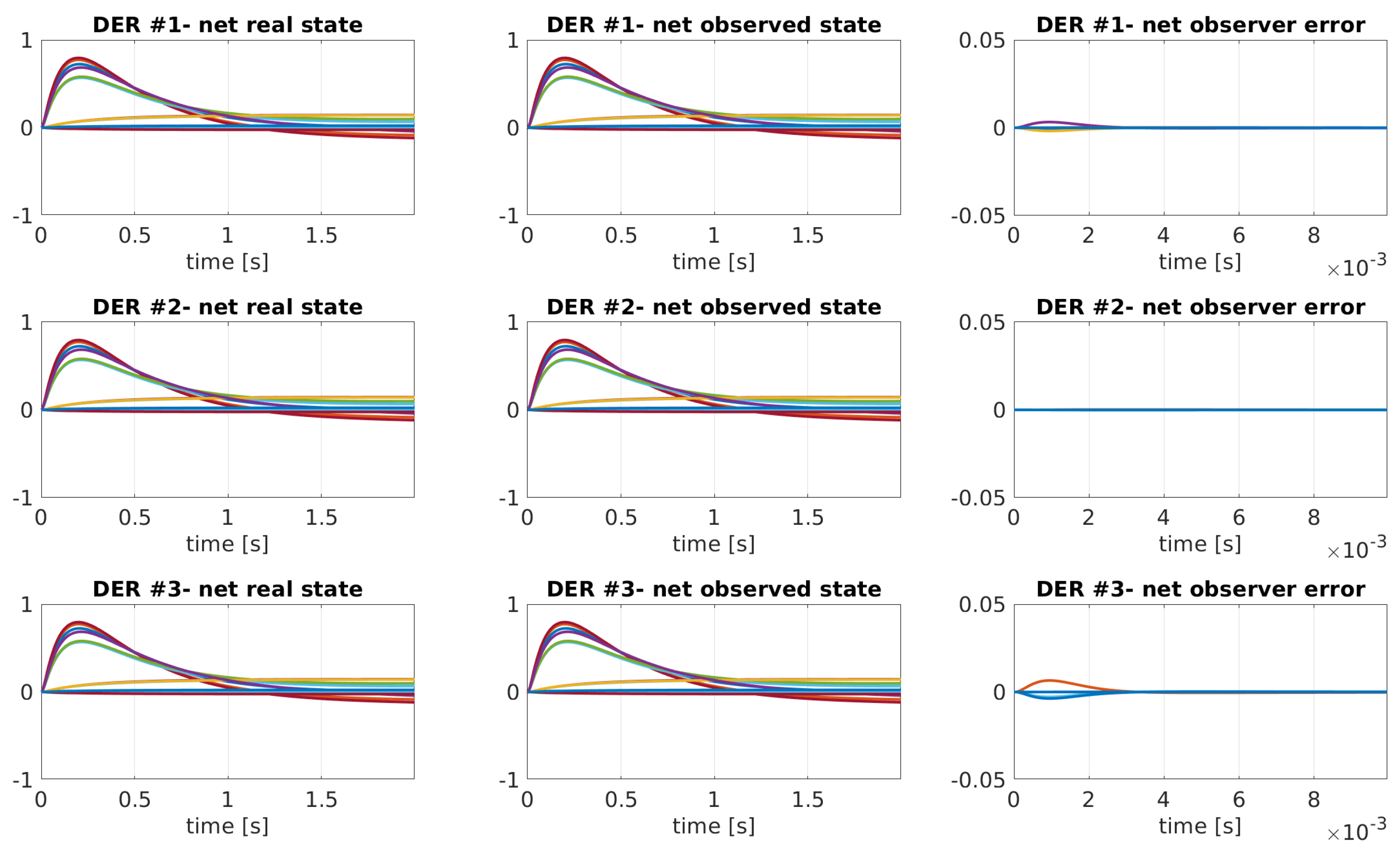
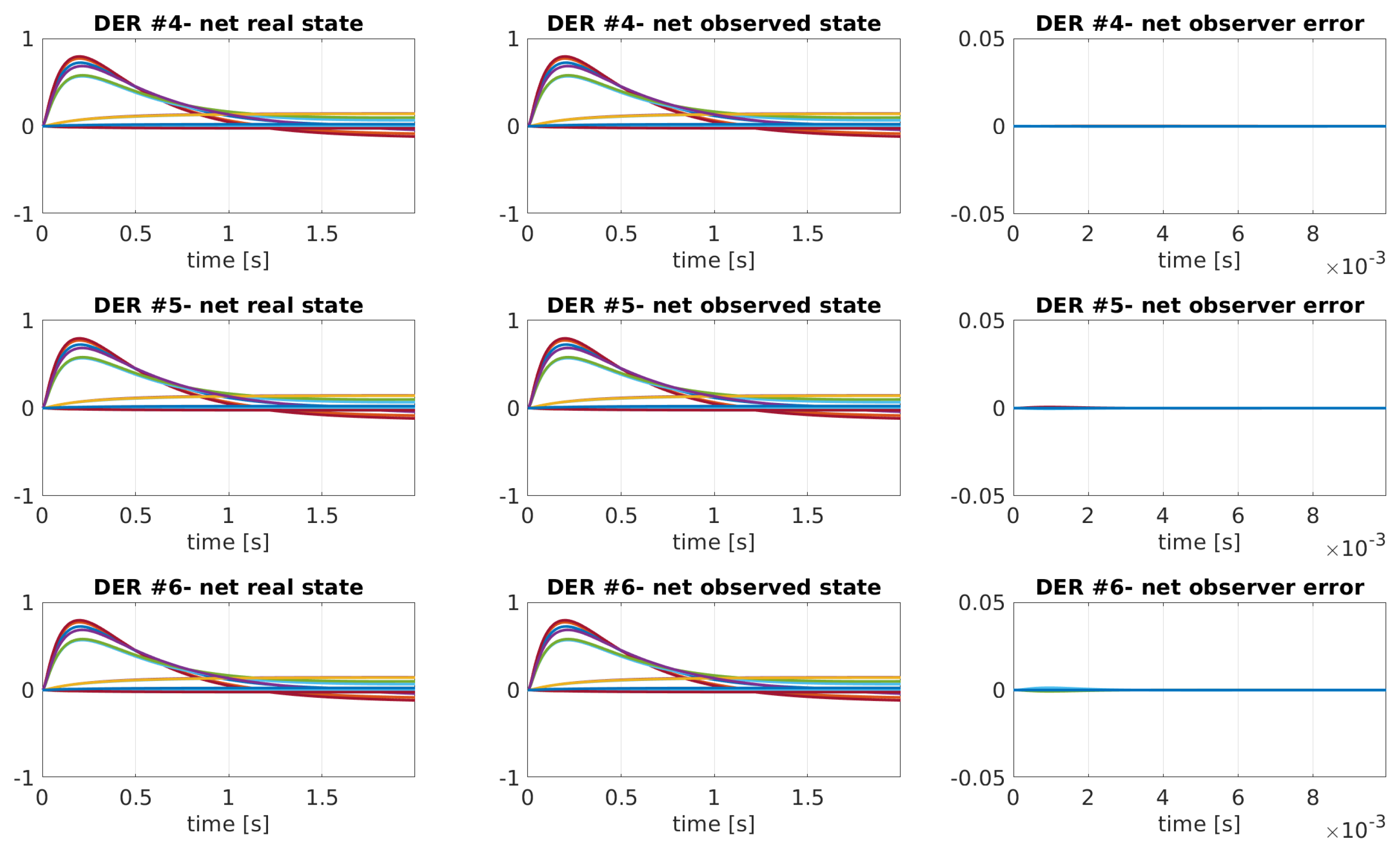
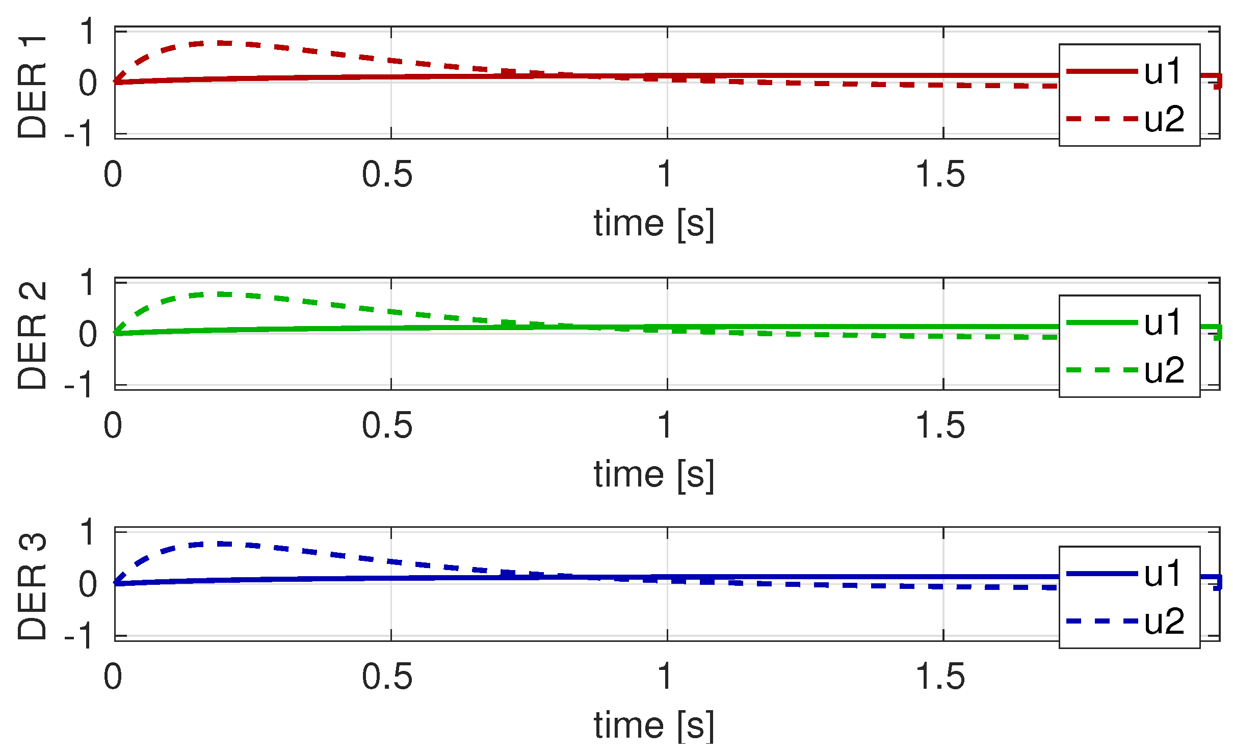
4. Numerical Validation

The proposed Cb-MPC has been tested on an ADN composed of 24 LV nodes with 6 DERs. The electric parameters of the ADN and the location and characteristic of the DERs are reported in [37]. Specifically, two feeders depart from the MV/LV substation, each one with a group of three DERs connected to different nodes. The DERs connected to the same feeder communicate among each other, whereas the two groups of DERs on different feeders communicate through only two DERs, respectively, #1 and #4. The resulting bidirectional topology of the communication network is characterized by the following Laplacian:
L = 0 1 1 1 0 0 1 0 1 0 0 0 1 1 0 0 0 0 1 0 0 0 1 1 0 0 0 1 0 1 0 0 0 1 1 0
which corresponds to the fully connected network reported in Figure 3.
The dynamic matrix of each DER is
A j = diag 83.3 76.9 66.6 74.0 66.6 74.0
corresponding to time constants around 15 ms. The collective dynamic matrix (14) is a diagonal composition of such matrices and presents the same eigenvalues. The coupling among DERs is the output matrix assumed equal to
T = 10 4 10170 64 78 46 167 62 1 29 1 29 0.6 28 342 127 156 92 335 125 2 57 3 57 1 57 70 46 10190 62 75 45 1 29 1 29 0.6 29 154 91 382 123 151 90 2 58 2 58 1 57 170 63 78 46 10260 74 1 29 1 29 0.6 28 340 127 155 91 515 148 2 57 3 57 1 57 0.7 28 1 28 0.4 28 10190 37 4 29 90 30 1 57 2 57 0.9 57 375 74 8 58 180 61 0.7 29 1 29 0.4 29 0.4 29 10270 43 3 29 1 57 2 57 0.9 57 8 59 542 87 6 59 0.7 28 1 28 0.4 28 94 33 4 29 10400 75 1 56 2 57 0.9 56 189 65 8 58 807 150
The overall system is implemented resorting to a simulation sampling time  T s , a target time constant for the local observer  τ o l , a target time constant for the consensus  τ o g , a communication sampling time  τ c o m m , and a target control time constant  τ c , which are assigned the values
T s = 50 μ s τ o l = 500 μ s = 0.5 ms τ o g = 5 ms τ c o m m = 50 ms τ c = 500 ms
which properly separate the observer and controller dynamics while accounting for the technical constraints.
For all the DERs, the reference values of the active powers are all equal to 0.15  p.u. on a 25 kVA basis (hereafter, all quantities are expressed in per unit relative to this basis), whereas the voltage reference values assume all the same variation equal to 0.01  p.u. with respect to the voltage value in the initial operating conditions; see the voltage bias in (13).
The network is assumed to start with a null initial condition (that is, no current injection by DERs) with a small observer error for four DERs out of six. The following constraints are included for the current components:
0 < i j , d 0.8 1 i j , q 1
The design uses the discretized model, and the local observers are implemented by resorting to a deterministic (Luenberger) observer with eigenvalues derived from the target time constant  τ o l . The consensus is implemented using (21) with k o = 10 3 , including or not including the communication sample and hold function with sampling time  τ c o m m . Once the controllability of the extended dynamic system has been verified, the MPC is implemented according to proposed solution with the given input–output constraints assuming in (25), the weight matrices
Q = diag 5 · 10 3 I 6 l 5 · 10 2 I 2 l S = diag 10 6 0 0 10 3 10 6 0 0 10 3 l times P = diag 5 · 10 3 I 6 l 5 · 10 2 I 2 l
and a horizon of ten samples ( N = 10 ). A heuristic procedure is implemented based on computing the equivalent Linear Quadratic Regulator and the related equivalent eigenvalues to design the weighting matrix and meet the target time constant τ c .
The results of the simulations with the proposed Cb-MPC implemented in Matlab R2023b environment are reported for the following case studies:
  • Case I: nominal case, i.e., ADN operating conditions are the same as the ones used in the Cb-MPC design without simulating the communication;
  • Case II: nominal case including the communication sample and hold functions;
  • Case III: comparison with an integral consensus-based controller designed using the eigenvalue assignment technique in the nominal case without simulating the communication;
  • Case IV: off-nominal case, i.e., different ADN operating conditions with respect to the ones assumed in the design.
Figure 4 shows the time evolution of the output quantities for all the DERs in Case I. It can be noticed that the desired values are reached by all the outputs with the target time constant  τ c . The output y R 2 l is defined in (12), and, in Figure 4, the line labeled yij refers to the output j (respectively, the active power for j = 1 and the voltage amplitude for j = 2 ) of the DER i, expressed in p.u.
Figure 5 and Figure 6 show the dynamics of the local observers for the two groups of DERs along, respectively, the first and the second feeder. From the plots in the third column, it is evident that the intentionally included initial error, if present, is recovered with the target time constant.
Figure 7 and Figure 8 show, for the first and the second group of DERs, respectively, the consensus dynamics, specifically, the time evolution of the system states, both the real and the observed values, and of the consensus errors. It is worth noticing that, for each DER, the error vector consists of 6 · l = 36 components.
Figure 9 and Figure 10 show the time evolution of the command input for each DER for the first and the second group of DERs, respectively. It can be noticed that the constraints are satisfied and the command is smooth.
Figure 11 shows the time evolution of the output quantities when sample and hold functions with sampling time T c o m m are included to simulate communication (Case II). A performance degradation can be noticed, which could be limited by increasing the frequency of data exchange.
Still referring to Case II, Figure 12 shows a time zoom of the time evolution of the collective states observed by the consensus algorithm for DER #1. It can be noticed that the information is exchanged every T c o m m , while the consensus algorithm is executed at a shorter sampling time.
For the sake of comparison, in Case III, DER controllers are designed using the eigenvalue assignment technique in place of the MPC approach, while the local observer and the consensus algorithm are left unchanged. The command input is saturated to the same values used for the MPC approach. Figure 13 shows the resulting time evolution of the output for all the DERs, and it can be stated that the performance is comparable with the one shown in Figure 4.
On the other hand, the proposed Cb-MPC scheme shows robustness with respect to the uncertainty in the model parameters. Case IV gives evidence of this robustness, simulating the ADN using a modified T  matrix, namely,
T = 10 4 10180 69 84 49 182 70 2 28 3 28 2 28 362 138 168 97 367 141 5 57 5 57 4 57 86 50 10200 66 86 51 2 29 3 29 2 29 171 100 398 132 172 101 5 58 5 58 4 58 179 68 83 48 10272 82 2 28 3 28 2 28 358 137 166 96 545 165 5 56 5 56 4 56 3 29 3 29 3 29 10194 41 5 29 102 37 5 57 6 57 5 57 388 82 11 58 204 75 3 29 3 29 3 29 5 30 10282 50 5 30 5 58 6 58 5 58 10 60 564 100 10 60 3 28 3 28 3 28 98 35 5 29 10427 89 5 56 5 56 5 57 197 71 11 58 854 179
which corresponds to different operating conditions of the ADN in terms of slack bus voltage and loads with respect to the ones assumed in the design. Comparing T and T , it is apparent that the elements are subject to large variations of up to 30 %. Figure 14 shows the time evolution of the output of all the DERs in Case IV. It can be noticed that the integral action guarantees a null steady-state error also in the presence of significant variations in the values of the matrix elements.
Still referring to Case IV, Figure 15 and Figure 16 show the time evolution of the command input for each DER. It can be noticed that the MPC controllers correctly cope with the saturation and maintain a stable behavior.

5. Conclusions

Active power and voltage control of distributed energy resources (DERs) in grid-connected active distribution networks (ADNs) are addressed in this paper. The control design is based on a multiple-input multiple-output model of the ADN, accounting for both internal and external interactions among the different control loops of the DERs. The proposed solution adopts a distributed controller–observer scheme in which each DER implements three tasks: a local deterministic observer, a distributed consensus algorithm, and a constrained MPC. Regarding communication requirements, each DER exchanges data only with its neighbors. Numerical validation referring to an LV ADN with six DERs has been presented, giving evidence of the performance of the proposed solution. In particular, the proposed control scheme is stable and guarantees null steady-state output errors also in the presence of uncertainty in the model parameters and of sample and hold functions in the communication among the DERs. Future work will focus on implementing alternative types of controllers still based on the proposed distributed consensus algorithm.

Author Contributions

Conceptualization, G.A., G.F. and M.R.; Methodology, G.A., G.F. and M.R.; Software, G.A., G.F. and M.R.; Validation, G.A., G.F. and M.R.; Formal analysis, G.A., G.F. and M.R.; Investigation, G.A., G.F. and M.R.; Resources, G.A., G.F. and M.R.; Data curation, G.A., G.F. and M.R.; Writing—original draft, G.A., G.F. and M.R.; Writing—review & editing, G.A., G.F. and M.R.; Visualization, G.A., G.F. and M.R.; Funding acquisition, M.R. All authors have read and agreed to the published version of the manuscript.

Funding

This work was supported by the Project “Ecosistema dell’innovazione—Rome Technopole” financed by the EU in the NextGenerationEU plan through MUR Decree no. 1051 23.06.2022-CUP H33C22000420001.

Data Availability Statement

The original contributions presented in the study are included in the article, further inquiries can be directed to the corresponding author.

Conflicts of Interest

The authors declare no conflicts of interest.

References

  1. Tatar, S.M.; Aydin, E. Design and operation of renewable energy microgrids under uncertainty towards green deal and minimum carbon emissions. Sustain. Energy Grids Netw. 2024, 37, 101233. [Google Scholar] [CrossRef]
  2. Sun, H.; Guo, Q.; Qi, J.; Ajjarapu, V.; Bravo, R.; Chow, J.; Li, Z.; Moghe, R.; Nasr-Azadani, E.; Tamrakar, U.; et al. Review of Challenges and Research Opportunities for Voltage Control in Smart Grids. IEEE Trans. Power Syst. 2019, 34, 2790–2801. [Google Scholar] [CrossRef]
  3. Antonelli, G. Interconnected dynamic systems. An overview on distributed control. IEEE Control Syst. Mag. 2013, 33, 76–88. [Google Scholar]
  4. Olfati-Saber, R.; Murray, R. Consensus problems in networks of agents with switching topology and time-delays. IEEE Trans. Autom. Control 2004, 49, 1520–1533. [Google Scholar] [CrossRef]
  5. Ren, W.; Beard, R.; Atkins, E. Information consensus in multivehicle cooperative control. IEEE Control Syst. Mag. 2007, 27, 71–82. [Google Scholar]
  6. Valverde, G.; Van Cutsem, T. Model predictive control of voltages in active distribution networks. IEEE Trans. Smart Grid 2013, 4, 2152–2161. [Google Scholar] [CrossRef]
  7. Zhao, H.; Wu, Q.; Wang, J.; Liu, Z.; Shahidehpour, M.; Xue, Y. Combined Active and Reactive Power Control of Wind Farms Based on Model Predictive Control. IEEE Trans. Energy Convers. 2017, 33, 1177–1187. [Google Scholar] [CrossRef]
  8. Li, P.; Ji, J.; Ji, H.; Jian, J.; Ding, F.; Wu, J.; Wang, C. MPC-based local voltage control strategy of DGs in active distribution networks. IEEE Trans. Sustain. Energy 2020, 11, 2911–2921. [Google Scholar] [CrossRef]
  9. Dutta, A.; Ganguly, S.; Kumar, C. Coordinated control scheme for ev charging and volt/var devices scheduling to regulate voltages of active distribution networks. Sustain. Energy Grids Netw. 2022, 31, 100761. [Google Scholar] [CrossRef]
  10. Cabrera-Tobar, A.; Pavan, A.M.; Blasuttigh, N.; Petrone, G.; Spagnuolo, G. Real time Energy Management System of a photovoltaic based e-vehicle charging station using Explicit Model Predictive Control accounting for uncertainties. Sustain. Energy Grids Netw. 2022, 31, 100769. [Google Scholar] [CrossRef]
  11. Bidgoli, H.S.; Van Cutsem, T. Combined local and centralized voltage control in active distribution networks. IEEE Trans. Power Syst. 2017, 33, 1374–1384. [Google Scholar] [CrossRef]
  12. Wang, L.; Dubey, A.; Gebremedhin, A.H.; Srivastava, A.K.; Schulz, N. MPC-based decentralized voltage control in power distribution systems with EV and PV coordination. IEEE Trans. Smart Grid 2022, 13, 2908–2919. [Google Scholar] [CrossRef]
  13. Kou, P.; Liang, D.; Gao, R.; Liu, Y.; Gao, L. Decentralized model predictive control of hybrid distribution transformers for voltage regulation in active distribution networks. IEEE Trans. Sustain. Energy 2019, 11, 2189–2200. [Google Scholar] [CrossRef]
  14. Wen, S.; Xiong, W.; Cao, J.; Qiu, J. MPC-based frequency control strategy with a dynamic energy interaction scheme for the grid-connected microgrid system. J. Frankl. Inst. 2020, 357, 2736–2751. [Google Scholar] [CrossRef]
  15. Balram, P.; Tuan, L.A.; Carlson, O. Comparative study of MPC based coordinated voltage control in LV distribution systems with photovoltaics and battery storage. Int. J. Electr. Power Energy Syst. 2018, 95, 227–238. [Google Scholar] [CrossRef]
  16. Nguyen, H.M.; Torres, J.L.R.; Lekić, A.; Pham, H.V. MPC based centralized voltage and reactive power control for active distribution networks. IEEE Trans. Energy Convers. 2021, 36, 1537–1547. [Google Scholar] [CrossRef]
  17. Ouammi, A.; Achour, Y.; Zejli, D.; Dagdougui, H. Supervisory model predictive control for optimal energy management of networked smart greenhouses integrated microgrid. IEEE Trans. Autom. Sci. Eng. 2020, 17, 117–128. [Google Scholar] [CrossRef]
  18. Karthikeyan, N.; Pillai, J.R.; Bak-Jensen, B.; Simpson-Porco, J.W. Predictive control of flexible resources for demand response in active distribution networks. IEEE Trans. Power Syst. 2019, 34, 2957–2969. [Google Scholar] [CrossRef]
  19. Maharjan, S.; Khambadkone, A.M.; Peng, J.C.H. Robust constrained model predictive voltage control in active distribution networks. IEEE Trans. Sustain. Energy 2021, 12, 400–411. [Google Scholar] [CrossRef]
  20. Fusco, G.; Russo, M. A decentralized approach for voltage control by multiple distributed energy resources. IEEE Trans. Smart Grid 2021, 12, 3115–3127. [Google Scholar] [CrossRef]
  21. Yazdanian, M.; Mehrizi-Sani, A. Distributed Control Techniques in Microgrids. IEEE Trans. Smart Grid 2014, 5, 2901–2909. [Google Scholar] [CrossRef]
  22. Andrén, F.; Bletterie, B.; Kadam, S.; Kotsampopoulos, P.; Bucher, C. On the Stability of Local Voltage Control in Distribution Networks With a High Penetration of Inverter-Based Generation. IEEE Trans. Ind. Electron. 2015, 62, 2519–2529. [Google Scholar] [CrossRef]
  23. Bolognani, S.; Carli, R.; Cavraro, G.; Zampieri, S. On the Need for Communication for Voltage Regulation of Power Distribution Grids. IEEE Trans. Control Netw. Syst. 2019, 6, 1111–1123. [Google Scholar] [CrossRef]
  24. Zeraati, M.; Golshan, M.E.H.; Guerrero, J.M. A consensus-based cooperative control of PEV battery and PV active power curtailment for voltage regulation in distribution networks. IEEE Trans. Smart Grid 2017, 10, 670–680. [Google Scholar] [CrossRef]
  25. Guo, Y.; Wu, Q.; Gao, H.; Shen, F. Distributed voltage regulation of smart distribution networks: Consensus-based information synchronization and distributed model predictive control scheme. Int. J. Electr. Power Energy Syst. 2019, 111, 58–65. [Google Scholar] [CrossRef]
  26. Dhulipala, S.C.; Monteiro, R.V.A.; da Silva Teixeira, R.F.; Ruben, C.; Bretas, A.S.; Guimarães, G.C. Distributed model-predictive control strategy for distribution network volt/var control: A smart-building-based approach. IEEE Trans. Ind. Appl. 2019, 55, 7041–7051. [Google Scholar] [CrossRef]
  27. Qi, W.; Liu, J.; Christofides, P.D. Distributed supervisory predictive control of distributed wind and solar energy systems. IEEE Trans. Control Syst. Technol. 2013, 21, 504–512. [Google Scholar] [CrossRef]
  28. Duan, J.; Wang, C.; Xu, H.; Liu, W.; Xue, Y.; Peng, J.C.; Jiang, H. Distributed control of inverter-interfaced microgrids based on consensus algorithm with improved transient performance. IEEE Trans. Smart Grid 2019, 10, 1303–1312. [Google Scholar] [CrossRef]
  29. Antonelli, G.; Arrichiello, F.; Caccavale, F.; Marino, A. A decentralized controller-observer scheme for multi-agent weighted centroid tracking. IEEE Trans. Autom. Control 2012, 58, 1310–1316. [Google Scholar] [CrossRef]
  30. Borrelli, F.; Bemporad, A.; Morari, M. Predictive Control for Linear and Hybrid Systems; Cambridge University Press: Cambridge, UK, 2017. [Google Scholar]
  31. Kailath, T. Linear Systems; Prentice-Hall: Englewood Cliffs, NJ, USA, 1980; Volume 156. [Google Scholar]
  32. Hu, J.; Ye, C.; Ding, Y.; Tang, J.; Liu, S. A distributed MPC to exploit reactive power V2G for real-time voltage regulation in distribution networks. IEEE Trans. Smart Grid 2021, 13, 576–588. [Google Scholar] [CrossRef]
  33. Xing, X.; Lin, J.; Wan, C.; Song, Y. Model predictive control of LPC-looped active distribution network with high penetration of distributed generation. IEEE Trans. Sustain. Energy 2017, 8, 1051–1063. [Google Scholar] [CrossRef]
  34. Subramanian, L.; Debusschere, V.; Gooi, H.B.; Hadjsaid, N. A distributed model predictive control framework for grid-friendly distributed energy resources. IEEE Trans. Sustain. Energy 2021, 12, 727–738. [Google Scholar] [CrossRef]
  35. Fusco, G.; Russo, M. Robust MIMO Design of Decentralized Voltage Controllers of PV Systems in Distribution Networks. IEEE Trans. Ind. Electron. 2017, 64, 4610–4620. [Google Scholar] [CrossRef]
  36. Fusco, G.; Russo, M.; Casolino, G.M. Voltage and active power local PI control of distributed energy resources based on the effective transfer function method. Int. J. Electr. Power Energy Syst. 2023, 152, 109264. [Google Scholar] [CrossRef]
  37. Fusco, G.; Russo, M. A Procedure to Determine the Droop Constants of Voltage Controllers Coping with Multiple DG Interactions in Active Distribution Systems. Energies 2020, 13, 1935. [Google Scholar] [CrossRef]
Figure 1. Typical configuration of a distribution system.
Energies 17 04490 g001
Figure 2. Overall architecture of the proposed control scheme. It is worth noticing that the output of each MPC, based on the local estimate of the collective state, is a collective input, but only the local components are effectively sent to the DER under control. The coupling matrix T is graphically represented as a block which connects all the DERs.
Energies 17 04490 g002
Figure 3. Communication network topology.
Energies 17 04490 g003
Figure 4. Case I. Time evolution of the output for all the DERs with the Cb-MPC (yij refers to the output j of the DER i).
Energies 17 04490 g004
Figure 5. Case I. Local observer quantities for the three DERs along the first feeder. From left to right for each DER: in the first column, the real states; in the second column, the observed states; and, in the third column, the estimation errors, zoomed to the first time instants.
Energies 17 04490 g005
Figure 6. Case I. Local observer quantities for the three DERs along the second feeder. From left to right for each DER: in the first column, the real states; in the second column, the observed states; and, in the third column, the estimation errors, zoomed to the first time instants.
Energies 17 04490 g006
Figure 7. Case I. Consensus quantities for the three DERs along the first feeder. From left to right for each DER: in the first column, the real collective states; in the second column, the observed collective states; and, in the third column, the consensus errors, zoomed to the first time instants.
Energies 17 04490 g007
Figure 8. Case I. Consensus quantities for the three DERs along the second feeder. From left to right for each DER: in the first column, the real collective states; in the second column, the observed collective states; and, in the third column, the consensus errors, zoomed to the first time instants.
Energies 17 04490 g008
Figure 9. Case I. Command input for the three DERs along the first feeder.
Energies 17 04490 g009
Figure 10. Case I. Command input for the three DERs along the second feeder.
Energies 17 04490 g010
Figure 11. Case II. Time evolution of the output for all the DERs including the sample and hold functions at T c o m m with the Cb-MPC (yij refers to the output j of the DER i).
Energies 17 04490 g011
Figure 12. Case II. Time zoom of the evolution of the collective state observed by the consensus algorithm for DER #1.
Energies 17 04490 g012
Figure 13. Case III. Time evolution of the output for all the DERs with the closed loops designed using the eigenvalue assignment technique (yij refers to the output j of the DER i).
Energies 17 04490 g013
Figure 14. Case IV. Time evolution of the output for all the DERs with the Cb-MPC (yij refers to the output j of the DER i).
Energies 17 04490 g014
Figure 15. Case IV. Command input for the three DERs along the first feeder.
Energies 17 04490 g015
Figure 16. Case IV. Command input for the three DERs along the second feeder.
Energies 17 04490 g016
Table 1. Main features of the proposed method compared with other methods in the literature.
MethodDER
Model
Network
Model
Consensus
Based
MPCIntegral
Action
Architecture
in [12]no dynamicscluster basednoyesnodecentralized
in [16]no dynamicslinearizednoyesnocentralized
in [19]no dynamicslinearizednoyesnocentralized
in [25]no dynamicslinearizedyesyesnodistributed
in [28]time domainmicro-gridnonoyesdistributed
in [34]time domainenergy communityyesyesyesdistributed
proposedtransfer functionlinearizedyesyesyesdistributed
Disclaimer/Publisher’s Note: The statements, opinions and data contained in all publications are solely those of the individual author(s) and contributor(s) and not of MDPI and/or the editor(s). MDPI and/or the editor(s) disclaim responsibility for any injury to people or property resulting from any ideas, methods, instructions or products referred to in the content.

