Review

Two-Dimensional Dual Jets—A Comprehensive Review of Experimental and Numerical Analyses

by
Paula J. Murphy
1,*,
Sajad Alimohammadi
2 and
Séamus M. O’Shaughnessy
1
1
Mechanical, Manufacturing & Biomedical Engineering, Trinity College, The University of Dublin, Dublin 02, D02 PN40 Dublin, Ireland
2
School of Mechanical Engineering, Technological University Dublin, Dublin 07, D07 H6K8 Dublin, Ireland
*
Author to whom correspondence should be addressed.
Energies 2024, 17(17), 4487; https://doi.org/10.3390/en17174487
Submission received: 26 July 2024 / Revised: 31 August 2024 / Accepted: 3 September 2024 / Published: 6 September 2024
(This article belongs to the Section K: State-of-the-Art Energy Related Technologies)

Abstract

:
A dual jet system, comprising a wall jet flowing tangential to a solid wall and a parallel offset jet, possesses a unique flow field that has proven advantageous in many industrial applications. Despite this, investigations of dual jets are severely underrepresented in the published literature, meaning their flow and heat transfer characteristics are yet to be fully understood. Many published studies dedicated to the characterization of dual jet flows are entirely numerical in nature, and significant discrepancies exist among the reported findings. This can be attributed to the distinct lack of experimental data related to dual jet flows, which has to date prohibited the full validation of any existing dual jet numerical model. The purpose of this report is to perform a comprehensive review of the available dual-jet literature to ascertain the present understanding of dual jet flow behavior and related heat transfer characteristics. An in-depth overview of dual jet flow theory is provided, and the reported effects of varying the major dual jets’ parameters are discussed, e.g., jet Reynolds number, jet offset ratio, and jet velocity ratio. In doing so, the major discrepancies among the relevant dual-jet studies are highlighted and a clear gap in the literature is identified. Recommendations for future studies on dual jets are provided.

1. Introduction

This study reviews in detail experimental and numerical analyses of the fluid flow and heat transfer behaviors of two-dimensional (2D) wall-bounded dual jets, where the term “dual jet” can refer to any jet configuration consisting of two coflowing jet streams. When a solid wall boundary is introduced, however, the now wall-bounded dual jet comprises a wall jet flowing immediately parallel to the solid boundary, alongside a coflowing offset jet whose inlet is offset from the solid boundary by some distance.
The characterization of wall-bounded dual jets is a topical area of research, comprising 50% of all related studies published since 2019. Despite this, the related published literature contains only limited information on their associated flow and heat transfer behaviors and lacks congruency, with predicted trends appearing inconsistent across multiple studies despite focusing on a similar range of jet parameters. As such, the available literature at present is insufficient for enabling the control and optimization of a wall-bounded dual jet flow, where the heat transfer capabilities of dual jet flows are still relatively misunderstood.
For this investigation, the primary focus is given to the topic of two-dimensional wall-bounded dual jets. Henceforth, for simplicity, the abridged term “dual jet” refers specifically to the combination of a planar wall jet and an offset jet. The term “wall jet” refers to a stream of fluid ejected immediately parallel to a solid boundary, and, when offset by some distance while maintaining the same flow direction, the fluid stream becomes an offset jet [1]. The resulting flow structure through the amalgamation of these two jet types is highly complex and distinctly different from that of a wall jet or offset jet in isolation, as shown by the velocity profiles in Figure 1, where the initial direction of the fluid at the nozzle exit is parallel for both jets, and the jets are of equal strength.

Industrial Applications of Dual Jets

Dual jets have various applications in industry, such as in entrainment processes, enhanced mixing, film-cooling, heat exchangers, and air conditioning, where the use of a dual jet offers an enhanced level of control and optimization compared to a single jet [2]. One of the most commonly encountered uses of a dual jet arrangement is for wastewater evacuation processes, whereby the enhanced mixing induced by a dual jet arrangement can help to quickly dilute pollutants to a safe level when discharged into a river or lake [3]. This is also an important factor when designing exhaust stacks, where the optimum distance between adjacent exhaust stacks must be identified to obtain the required level of mixing, while controlling the ratio of the exhaust velocities can help control the deflection of the exhaust plumes to avoid certain obstacles [4,5]. The improved mixing through the use of a dual jet has also proved advantageous in fuel injection systems, where the enhanced dispersion of fuel inside the combustion chamber can help improve the overall engine efficiency [6].
A wall-bounded dual jet is analogous to the setup within a gas turbine, as shown in Figure 2, where a cooler wall jet is used to shield the turbine blades from a coflowing stream of high-temperature gas, which could be in excess of the melting temperature of the turbine blade itself [7,8]. The efficiency of a gas turbine has been found to increase with increasing turbine inlet temperature, where an increase of 100 K represents an increase in efficiency of 2–3%. As a result, it is common to encounter gas temperatures in excess of 1950 K in the vicinity of the turbine blades, and it is expected that gas temperatures will exceed 2200 K in the near future [9]. With gas turbines and combined-cycle power stations accounting for approximately 22% of the global electricity production, the topic of turbine blade cooling is currently an important area of research, in particular the combination of film-cooling with air jet impingement.
The stabilization of an offset jet through the use of a thin, coflowing wall jet is commonly found in industry, particularly for cooling applications. This can be found in manufacturing processes such a blown film extrusion, which is crucial for the production of thin plastic films from 0.5 mm to 5 μm, where the addition of a wall jet to the cooling offset jet elongates the attachment length of the offset jet and significantly reduces fluctuations present in the flow [10,11]. This is achieved through the use of a dual lip ring located near the die, as shown in Figure 3, which cools the molten tubular film as it exits the die. The goal in this instance is to maximize the rate of solidification of the extruded material, where the output from the production line is generally limited by the cooling capabilities of the airflow [11]. Further to this, as instabilities in the airflow can induce deformities in the extruded product, the coflowing wall jet plays an important role in ensuring the quality of the final product.
The use of dual jets, or a multiple jet arrangement, is often the preferred choice for cooling purposes, not only for the increased rate of heat transfer that they can provide, but also for the noise suppression that can be achieved because of the jets’ interaction [12,13]. The use of dual jets as a means of noise suppression is common in aviation, where tight noise budgets imposed on airports and aircraft have heightened the need for improvement and further research in this area. In addition to this, the Advisory Council for Aeronautics Research in Europe (ACARE) have set out a Strategic Research and Innovation Agenda (SRIA), i.e., Flightpath 2050, to reduce aircraft noise pollution by 65% by 2050, ensuring noise reduction in aviation remains a topical area of research [14]. Examples of the use of dual jets in the suppression of the noise output from an aircraft include the use of a bypass nozzle to induce mixing with the core exhaust gases at the exit of the turbofan engine, as shown in Figure 4, and the use of dual planar air curtains on the landing gear or aircraft to reduce airframe noise [13,15].
Some of the studies detailed in this review are concerned with the heat transfer characteristics of a dual jet flow when used to cool a heated surface, such as that frequently encountered in the electronics cooling industry. The current need for effective thermal management solutions for electronic devices is a well-known issue, where the continuous miniaturization of electronic components has been found to significantly increase heat fluxes during normal operation. To ensure the device is operating within a safe temperature range and to improve the longevity of the device, heat fluxes up to the order of 1   M W / m 2 can require dissipation at present, such as that from advanced server equipment chips, which may pose challenges for many of the traditional methods of cooling [16]. There have been significant advancements in this area over recent years, such as the use of impinging jet arrays or minichannels; however, further enhancements are required on a continual basis as heat fluxes continue to rise [17,18]. Dual jet flows offer a possible solution in this regard, where the associated enhanced mixing can increase the rate of heat transfer from the heated surface, while an improved level of control would allow for tuning or optimization to a specific application. This sentiment is reflected across much of the published dual-jet studies, all of which cite electronics cooling as a potential application.
Figure 4. Noise suppression at the exit of a turbofan engine through the use of a coflowing bypass duct. (a) “Acoustic liners” © 2020 by M. Sadeghian, from “Technologies for aircraft noise reduction: A review” in Journal of Aeronautics & Aerospace Engineering, Vol. 9(1), no. 219. Retrieved from https://www.longdom.org/open-access/technologies-for-aircraft-noise-reduction-a-review-47567.html#:~:text=Passive%20control%20involves%20reducing%20the,and%20jet%20or%20exhaust%20jets, licensed under CC BY 4.0 by the authors (https://creativecommons.org/licenses/by/4.0/), accessed 1 July 2024 [19]. (b) “The structure of jet flow of turbofan engines with separate exhaust” © 2022 by Ji et al., from “Active jet noise control of turbofan engine based on explicit model predictive control” in Applied Sciences, vol. 12, no. 10, p. 4874. Retrieved from https://doi.org/10.3390/app12104874, licensed under CC BY 4.0 by MDPI, Basel, Switzerland (https://creativecommons.org/licenses/by/4.0/), accessed 1 July 2024 [15].
Energies 17 04487 g004

2. Comparison of Jet Flow Configurations

Though the purpose of this review is to investigate the flow behavior and heat transfer characteristics associated with a two-dimensional dual jet, a general understanding of other 2D jet flow configurations is required to achieve this. This section provides an overview of the various jet flow structures and introduces relevant terminology. First, important features relating to both free jets and various wall-bounded jet flow configurations are outlined. Subsequently, the relevant findings are incorporated into the dual-jet discussion to provide context for certain flow features. For the sake of brevity, the discussion is limited to fully turbulent jet flows only, as their use is considerably more prevalent across industrial applications. This is due to the enhanced mixing and superior heat transfer that can be acquired compared to a jet flow within the laminar or transitional flow regime. The critical Reynolds number ( R e c r ) for a free jet has been previously found to exist in the region of 2000 R e c r 3000 , depending on whether a planar or round jet was considered [20,21,22].

2.1. Turbulent Free Jets

Turbulent free jets have been reported extensively throughout the published literature, with notable studies such as by Miller and Comings [23], Wygnanski and Fiedler [24], Westerweel et al. [25] and Gutmark and Wygnanski [26]. A free jet is formed when a stream of fluid is discharged from a nozzle into quiescent surroundings, where no solid boundaries exist downstream of the jet nozzle exit to influence the jet development [27]. A distinction does exist, however, between free jets that emerge into an ambient fluid of similar density, termed a submerged jet, or those of lesser density, i.e., a free surface jet [28]. As this investigation is only concerned with the properties associated with a submerged jet, the use of the term ‘jet’ for the remainder of this literature review refers exclusively to submerged jets.
The category of turbulent free jets can be further subdivided into axisymmetric jets, rectangular jets, or plane jets, depending on the nozzle shape at the jet exit. In the case in which a jet is issued from a round nozzle, the jet is considered round or axisymmetric, while a rectangular jet is acquired through the use of a rectangular nozzle, where it has been shown that a rectangular jet can possess much higher rates of entrainment and enhanced mixing compared to an axisymmetric jet due to the presence of higher order instability modes [29,30]. In the case where the length (z-dimension) of the rectangular nozzle compared to its width (y-dimension), i.e., the aspect ratio, is sufficiently large, 3D effects arising from the presence of the shorter edge become negligible, resulting in a flow field that is statistically two-dimensional in the streamwise x- and transverse y-directions, but independent of variations along the spanwise z-direction [31]. The resulting jet flow is often referred to as a slot jet when analyzed as a three-dimensional flow structure; however, when idealized as a two-dimensional flow field along the xy-plane to simplify the flow analysis, it is termed a plane jet. The remainder of this discussion, therefore, focuses on the free plane jet, as the flow features are more closely aligned with those of a two-dimensional dual jet flow field, which is the primary focus of this investigation.

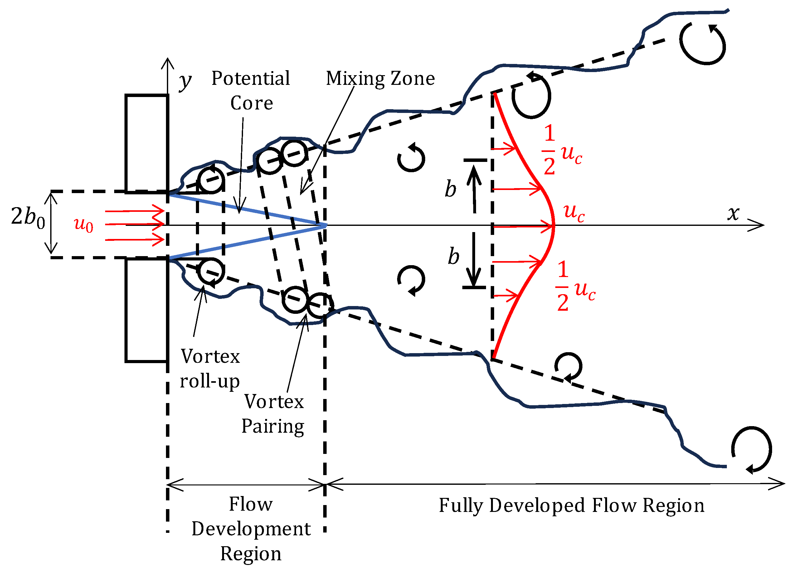
2.1.1. Single Plane Jet

The time-averaged flow structures associated with a free single-plane jet issuing from a slot nozzle of width 2 b 0 can be seen in Figure 5 [32]. As the fluid issues from the nozzle exit, a thin region of high vorticity, or shear layer, is formed between the high velocity jet fluid and the quiescent surroundings [27]. This arises as a result of Kelvin–Helmholtz instabilities in the fluid flow, where Kelvin–Helmholtz instabilities are defined as flow instabilities that arise as a result of a velocity or density difference across a finite thickness within a fluid domain, i.e., a discontinuity in the fluid velocity or density field [33,34]. This leads to the formation of roll-up vortices at the nozzle exit, which, when convected downstream, can pair up with like-signed regions of vorticity to form much larger vortical structures [35,36]. In doing so, surrounding ambient fluid is drawn into the jet flow which acts to slow the average jet velocity to maintain the momentum flux as the mass flow rate of the jet increases [27,37]. This process is referred to as entrainment, and it is responsible for the spreading of the jet in the vertical dimension and its eventual demise farther downstream.
This leads to the formation of two distinct downstream regions in the jet flow field, i.e., the flow development region and fully developed flow region [32]. The flow development region is located closest to the jet inlet and is characterized by the presence of the potential core, within which the initial jet exit velocity, u 0 , is conserved. The width of the potential core initially equates to the jet width at the nozzle inlet; however, as the thickness of the shear layer grows with streamwise distance, the width of the potential core decreases until its eventual depletion at some point downstream. The potential core length is, hence, defined as the streamwise distance along the jet centerline from the jet exit to a location at which the local fluid velocity is u = 0.95 u 0 , which is expected to be at approximately 12 b 0 for a plane jet [32,38].
In the fully developed region, the velocity profile describing the variation in the streamwise velocity, u, along the transverse y dimension acquires a distinct geometrical shape that remains relatively consistent at each streamwise position. That is, at each downstream location, the maximum streamwise velocity, u c , exists at the jet centerline, i.e., y = 0 m, and decays continuously toward 0 m/s with increases in y [32]. Because of the effects of entrainment with the ambient fluid, the jet flow spreads increasingly along the vertical direction with increasing streamwise distance, which subsequently reduces the value of u c with an increase in x. As the actual jet’s width is quite difficult to identify experimentally, the streamwise jet’s development, or jet spreading, is generally monitored in terms of the jet half-width, b , defined at each x-location as the distance in the transverse direction from the jet centerline to a location where the local streamwise velocity is half of that at the jet centerline, i.e., u b = u c / 2 [27,32].
When analyzing the development of the local velocity profile, it is common to nondimensionalize the velocity values with respect to the centerline velocity, u c , while the transverse dimension is generally scaled using the jet half-width. In plotting u / u c against y/b, it has been noted that the velocity distributions begin to collapse along a common curve after a certain streamwise distance, which is often referred to as a jet flow reaching self-similarity [8,13,20]. In this region, the nondimensionalized velocity profile does not appear to vary with the streamwise distance, meaning the flow behavior is considerably more predictable in this region, and the mean flow statistics are somewhat independent of the jet conditions at the nozzle exit [39,40]. After some streamwise distance, the self-similarity associated with a jet flow will begin to break down, as um slows significantly and the jet reaches its eventual end.
When compared to a free laminar jet, the overall flow structure of a single free turbulent jet generally resembles that of its laminar counterpart with regard to the existence of an initial potential core region followed by the acquisition of self-similarity. The finer details, however, differ greatly [41]. In the case of a fully laminar jet, i.e., R e < 500 according to Pearce [42], the dominant viscous forces act to rapidly dampen any instabilities that may arise in the flow field, thus preventing the formation of turbulent eddies and maintaining a flow direction parallel to the streamwise dimension [21]. The presence of shearing between the jet flow and the quiescent fluid still entrains additional fluid into the jet flow, enabling the laminar jet to spread laterally in a similar manner to the turbulent jet, which ultimately reduces the mean jet velocity with an increasing downstream distance as the mass flow rate increases [43]. The spreading rate of a laminar jet, as originally derived by Schlichting [44] based on boundary layer theory, is significantly less than that of a turbulent jet, whereby the presence of turbulent eddies enhances mixing and greatly increases the rate of fluid entrainment into the jet flow. A fully laminar jet is rarely encountered in practical applications, and it is generally expected that an initially laminar jet will eventually break down into turbulent eddies beyond some downstream distance, i.e., the laminar length, thus indicating a jet Reynolds number within the transitional regime [45]. Upon transition, the lateral spread of the jet flow increases suddenly, where the jet spreading rate decreases with an increase in R e , in addition to a shortening of the laminar length. Within a fully turbulent flow regime, the spreading rate of the jet reaches a constant value that is independent of R e , and the laminar length no longer exists [21].

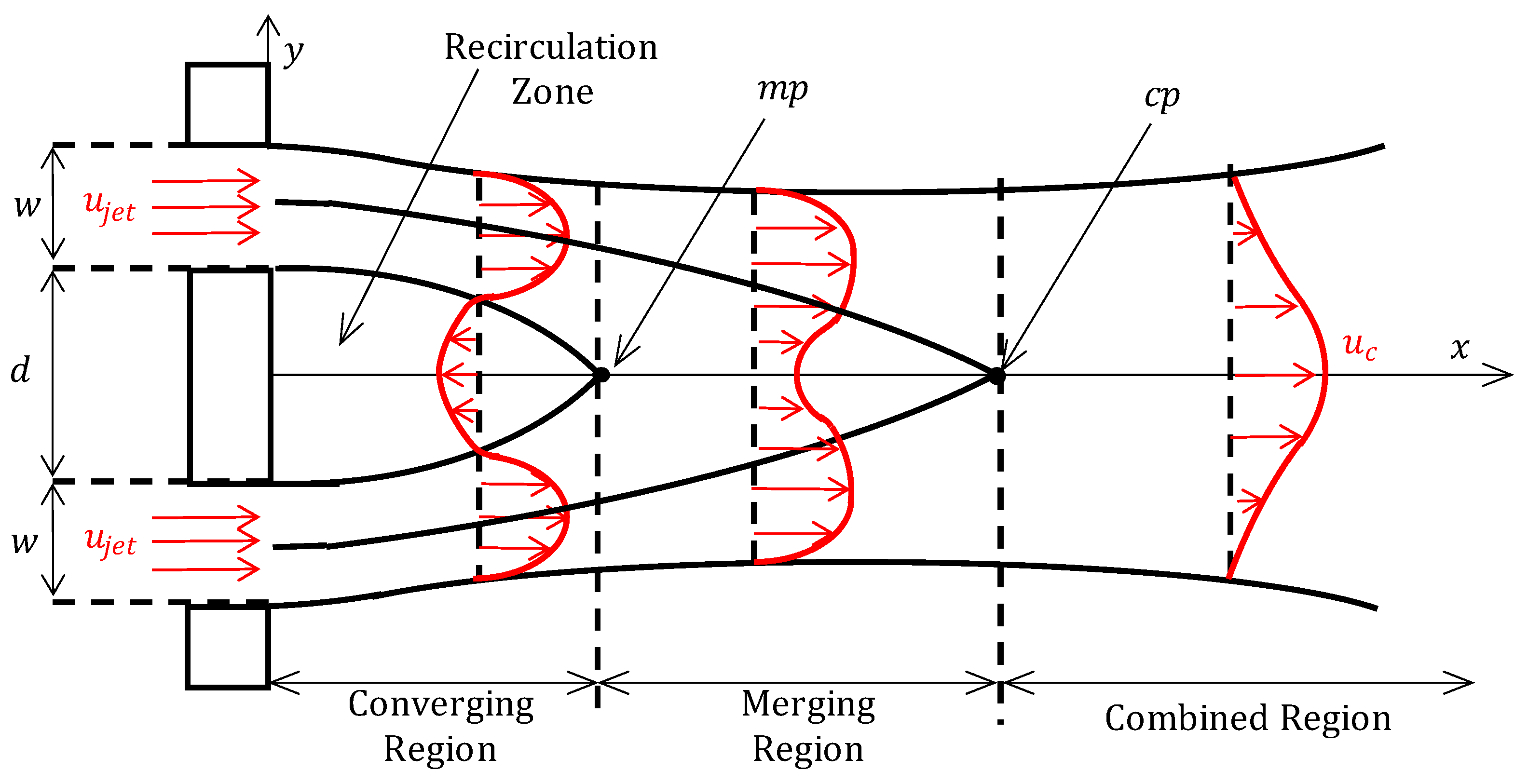
2.1.2. Plane Parallel Jet

While single free jets have an abundance of uses in industry, it is also common to encounter multiple plane jets in close proximity due to the enhanced mixing or control that may bring to a specific application, for example, fuel injection systems, thrust augmenting ejectors for vertical and/or short take-off and landing (V/STOL) aircraft, and dilution of thermal pollution [5,46,47].
A plane parallel jet is formed when two free slot jets are ejected from the same x = 0 plane, with the initial inlet directions of both jets parallel to the x -axis, as well as one another. The flow schematic can be viewed in Figure 6, which was first investigated experimentally in work carried out by Miller and Comings [48]. In this schematic, two 2D slot jets of width w are separated by the distance d or by a nondimensionalized separation ratio of d / w , where the x-axis acts as a plane of symmetry. Upon ejection from their respective nozzle exits, a shear layer forms along the inner and outer edges of each jet, where “inner” refers to the side closest to the opposing jet. The mutual entrainment of both jets with the central column of fluid leads to the creation of a low-pressure zone, or recirculation zone, between them, which causes the jets to deflect toward each other and eventually merge at some downstream location. The location at which the inner shear layers of both jets first meet is termed the merge point, mp, at which the mean flow velocity is 0 m/s, and the pressure reaches a local maximum value [49,50]. The downstream region extending from the jet exit plane to the merge point, encapsulating the full recirculation zone, is termed the converging region, the length of which can readily be controlled through adjusting the jet separation d. In doing so, it has been observed that a specific range of separation values exist that induce an unsteady flow regime inside the recirculation zone, where vortices are shed in a periodic manner similar to flow past a bluff body. Outside of this range of jet separation values, two steady, counter-rotating vortices have been observed inside this recirculation zone [5].
Downstream of the merge point, the interaction between the jets begins, continuing over the entire length of the merging region [5]. Within the merging region, the velocity along the centerline between the two jets increases steadily toward a maximum value, um, at the combined point, cp, at which the jets are considered to be fully combined and the local velocity profile no longer contains a negative deflection coinciding with the jet centerline [49]. Downstream of the combined point, within the combined region, the two jets behave as an equivalent single free jet [51]. In this region, the combined jet continues to spread in a linear fashion with downstream distance, where the rate at which this occurs has been shown to increase with increasing jet separation. Eventually, the combined jet flow reaches a self-similar state. While this flow structure is typical of the plane parallel jet behavior, research has shown that the extent of the jet mixing or jet deflection can be further controlled through altering the ratio of the jet inlet velocities or the respective sizes of the nozzle inlets, which can be advantageous when tuning to a specific application. For example, Fujisawa et al. [52] found that through adjusting the ratio of the jet inlet velocities, the extent of the deflection of the weaker jet is increased, which biases the transverse positions of both mp and cp toward the stronger jet and away from the jet centerline. More recently, Nassira and Amina [53] noted an enhanced mixing of jets of higher temperatures due to increased buoyancy effects, whereas cooler jets were notably less prone to merging.

2.2. Wall-Bounded Turbulent Jets
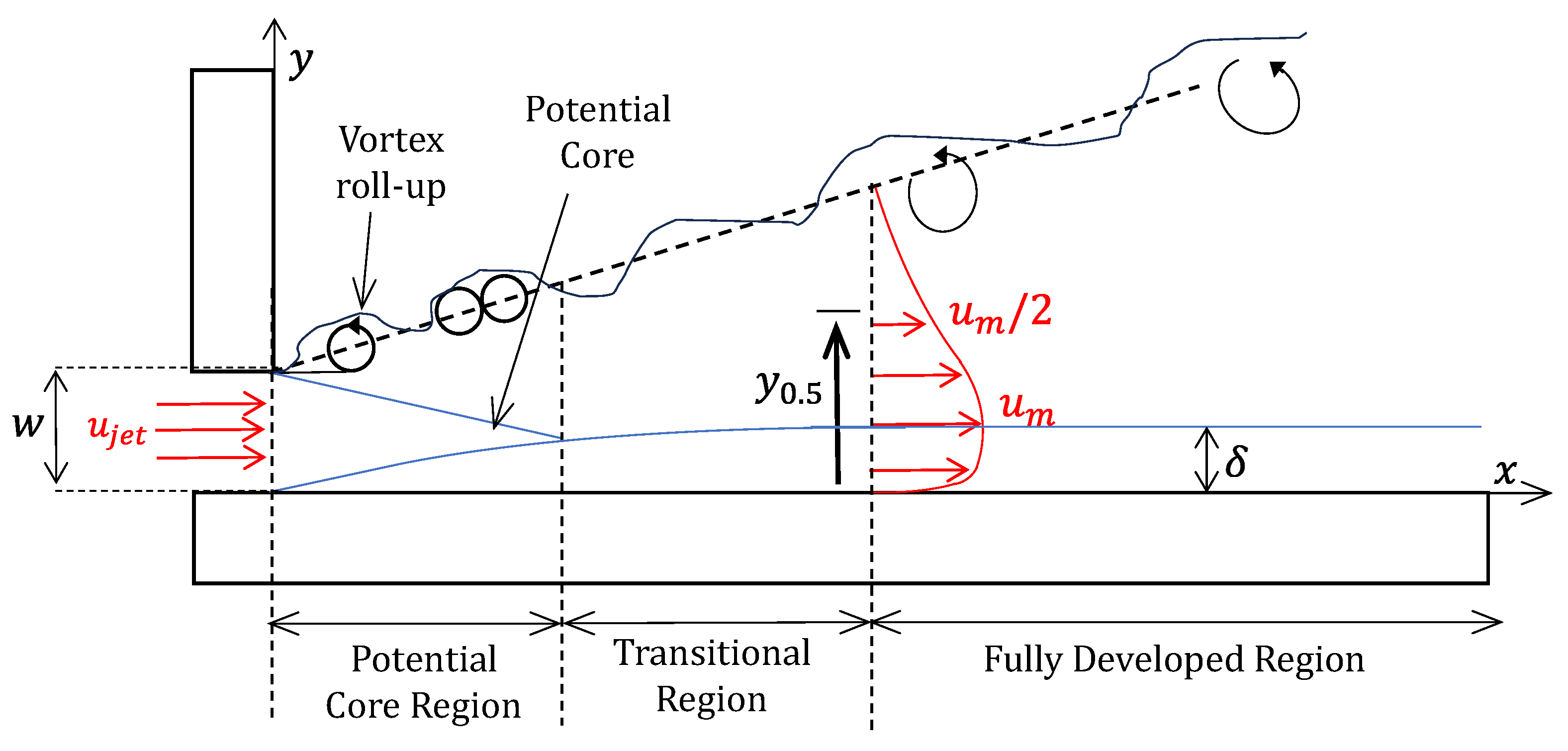
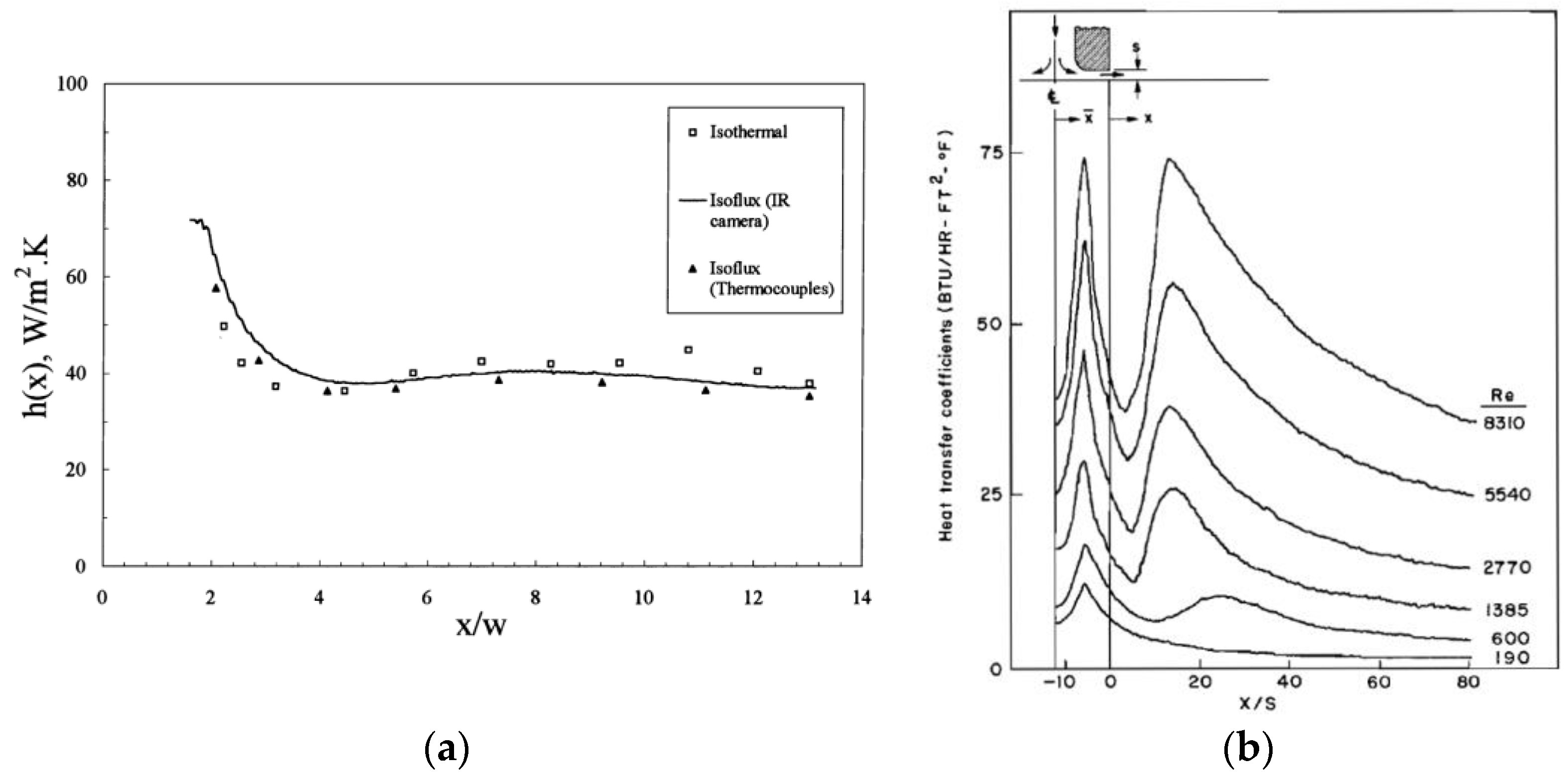
The use of turbulent jets as an effective means of cooling generally involves the impingement of the jet flow onto a heated solid surface, thus introducing a wall-bounded aspect to the turbulent jet flow. However, the use of wall-bounded jet flows is not exclusive to heat transfer applications. The influence of the wall on the jet flow structure depends on the jet proximity to the wall, as well as the direction of impingement. In the case of direct impingement, the jet is classified as an impinging jet which possesses a distinct flow structure. Impinging jets have been reported on extensively throughout the published literature in studies such as Lytle and Webb [54], Donaldson and Snedeker [55], and Jambunathan et al. [56]. The present investigation is concerned, however, with jets which flow parallel to the solid surface, either directly tangential, i.e., a wall jet, or offset from the wall boundary by some distance, i.e., an offset jet. The following sections briefly discuss the flow and heat transfer characteristics associated with wall and offset jets.

2.2.1. Wall Jets

A wall jet is formed when a jet, usually a slot jet, is discharged tangentially to a solid wall surface. The flow characteristics of a wall jet have previously been a popular area of research throughout the published literature due to their wide range of industrial applications, for example, Eriksson [57], Craft and Launder [58], Nizou [59], and AbdulNour et al. [60]. The basic flow structure of a two-dimensional wall jet is shown in Figure 7, where the downstream fluid flow development is distinctly different to that of a free jet. The presence of the wall dampens the growth of large-scale eddies, which thus reduces the rate of entrainment and the downstream decay of maximum velocity compared to the free jet [61].
Within the wall jet flow structure there exists the following two separate shear layers: the inner shear layer and the outer shear layer. The inner shear layer corresponds to the development of the viscous boundary layer along the solid wall boundary, where the no-slip condition ensures the fluid particles directly adjacent to the surface remain stationary. The boundary layer thickness, δ b l , at each x location is, hence, defined as the measured distance along the y -axis from the solid wall to a location corresponding to 99% of the local maximum streamwise velocity, u m , i.e., u = 0.99 u m [62]. Conversely, the outer shear layer is free to develop in a similar manner to a free jet, whereby the existence of a velocity difference between the flowing jet and the surrounding quiescent fluid leads to the formation of large-scale vortices due to the occurrence of Kelvin–Helmholtz instabilities. The development of the outer shear layer at each x -location is monitored by means of the jet half-width, y 0.5 , which corresponds to the perpendicular distance from the bounding wall to the position at which the local streamwise flow velocity equates to half of the maximum value measured at a given x -location, i.e., u = u m / 2 [32].
The fluid structure of a plane wall jet is divided into three downstream regions. Similar to a free jet, the length of the region closest to the jet exit is defined by the existence of the potential core, i.e., the potential core region. Beyond this is the transitional region, where, because of the prior demise of the potential core, the inner and outer shear layers are now free to interact. Within this region, the wall jet transitions from laminar to turbulent flow as the large-scale vortical structures within the outer shear layer pair with the smaller scale vortices in the inner shear layer, which are of opposing sign [62,63]. The intensity of the vortical structures within the inner shear layer has been shown to grow in strength with downstream distance, such that their associated strength is much greater than that of the outer shear layer, which enables the wall jet to cling to the surface over the total downstream distance [62]. The wall jet finally reaches a fully turbulent state within the fully developed region, at which point the jet flow achieves self-similarity [61].
The characteristic heat transfer profile associated with a two-dimensional wall jet flow is presented in Figure 8a,b in terms of the heat transfer coefficient h , as obtained by AbdulNour et al. [60] and Akfirat [64], respectively. In each case, h immediately decreases upon exiting the jet nozzle toward a minimum value, the position of which is relatively similar for both studies. This decline has previously been attributed to the growth in the wall boundary and degradation of the potential core, where the local minimum point coincides with the potential core length. Beyond this point, the interaction between the outer shear layer and the wall-boundary layer induces a sudden transition to turbulence in the wall-boundary layer, which subsequently causes a rise in the heat transfer coefficient along this region [64].
The growth in h due to the increasingly turbulent boundary layer reaches a limiting point, however, where h appears to reach a maximum value and subsequently declines over the remaining downstream distance. In each case, this was attributed to the continouous thickening of the wall-boundary layer, as well as the slowing of the overall mean jet velocity as entrainment effects began to dominate [60]. In similar work carried out by Mabuchi and Kumada [65], it was noted that the respective positions of the local minimum and maximum values in the heat transfer coefficient profile remain relatively unchanged for varying Reynolds number; however, an enhancement in the rate of heat transfer at each downstream location was observed for increases in R e , which was consistent with that presented by Akfirat [64].

2.2.2. Offset Jets

An offset jet is created when a slot jet is discharged from a vertical plane into the ambient fluid near a solid wall, where the wall is parallel to the jet inlet direction [66]. The fluid flow schematic for a two-dimensional offset jet can be seen in Figure 9, which is often considered similar to that of a backward facing step [67]. In the schematic, the jet nozzle is offset from the solid wall by a distance H , which is often nondimensionalized by means of the offset ratio, i.e., O R = H / w . Similar to previous jet setups, the jet flow in the downstream direction is divided into the following three distinct regions based on the flow behavior: recirculation region, impingement region, and wall region [68].
The recirculation region occurs closest to the nozzle exit and is characterized by the presence of the recirculation zone. Just downstream of the nozzle exit, the jet flow is momentum dominated, meaning the jet develops in a similar manner to that of a free jet [69]. However, the presence of the wall boundary induces unequal rates of entrainment above and below the jet, leading to the creation of a low-pressure zone directly below the jet exit, termed the recirculation zone. This low-pressure region causes the jet to deflect toward the wall and eventually impinge on the boundary at some downstream location, i.e., the Coanda effect. At the point where the jet flow attaches to the wall, i.e., the reattachment point x r p , part of the inner shear layer is deflected upstream due to the presence of an adverse pressure gradient, thus contributing to the creation of a large vortical structure within the recirculation zone [67,68]. While the recirculation zone is primarily dominated by the presence of a single recirculation bubble, a secondary recirculation region has been found to exist in close proximity to where the solid wall meets the jet exit plane [70]. The offset ratio has been shown to heavily influence the extent of the recirculation zone, whereby an increase in the offset ratio increases the length of the recirculation zone and the reattachment point is pushed farther downstream [71].
Beyond the reattachment point exists the impingement region, within which the jet centerline continues to deflect toward the wall. Within this region, the growth of a boundary layer at the wall surface, as well as subsequent interactions between the boundary layer and the outer shear layer, enable the jet to cling to the surface [67]. As the jet flow progresses, it has been found that at some downstream locations (within the wall region), the flow resembles that of an equivalent wall jet and will continue to develop in a similar manner.
The characteristic local Nusselt number, N u x , profiles reported by Kim et al. [70] and Song et al. [72] for a 2D single offset jet flow are presented in Figure 10a and Figure 10b, respectively. In each case, a sharp decline in N u x was observed immediately after the jet inlet is attributed to the secondary recirculation zone. The subsequent rise in N u x coincides with the more dominant recirculation bubble, where the local maximum N u x value occurs in conjunction with the reattachment point [70]. The final decline in N u x beyond this point is consistent with the jet flow continuing to develop in a manner similar to the single wall jet. The effect of O R on the N u x profile is clear in each case, whereby the downstream movement of x r p with an increase in O R consequentially increasing the streamwise position of the maximum N u x value. In doing so, the maximum N u x value decreased incrementally as the offset jet velocity at the impingement location became increasingly smaller. Downstream of x r p , a close alignment is observed among the respective N u x profiles at each O R , as the mass flow rate remains consistent throughout.

2.3. Dual Jets

The term “dual jet” throughout the published literature is generally used to describe a wall and offset jet combination, with both nozzle inlets aligned along the x = 0 plane. The restriction of the fluid flow in such a manner inhibits the jet’s development, which results in a highly complex flow structure quite different to a conventional plane parallel jet setup. While this terminology is somewhat vague considering the distinct wall-bounded nature of this particular jet flow configuration, where the label “dual jet” could technically be applied to any double jet flow configuration, it is used liberally throughout the published literature to refer specifically to the wall and offset jet combination. For this reason, this terminology is also adopted for the present investigation, where the use of the term “dual jet” for the remainder of the study refers to the wall-bounded wall jet and offset jet combination.
Much of the information presently available regarding dual jets has been derived from a limited number of numerical studies, while only a handful of experimental studies have been reported to date. The generally accepted, time-averaged two-dimensional dual jet flow structure can be seen in Figure 11, which was originally devised by Wang and Tan [73] based on the published work of Nasr and Lai [74] for plane parallel jets. The schematic shows two rectangular slot jets, a wall jet, and an offset jet, emerging into the quiescent ambient fluid from the same vertical plane, where the intersection of said vertical plane with the solid wall boundary defines the origin of the coordinate system. In this schematic, the working fluid is common to both the wall jet and the offset jet and is discharged parallel to the positive x-direction with initial streamwise mean velocities of u w and u o , respectively. The velocity ratio, V r , is hence defined as the ratio of the jet mean streamwise velocities, such that V r = u w / u o .
In Figure 11, the characteristic jet width, denoted by w , corresponds to the vertical jet dimension along the y-axis and is identical for both jets in this case. All locations within the flow domain are generally expressed in a nondimensional form with respect to the jet width, such that X = x / w and Y = y / w . The jet width is also interpreted as the appropriate characteristic length value when describing each jet flow in the dual-jet configuration by means of the nondimensional Reynolds number, such that R e j e t = u j e t w / υ , where u j e t is the corresponding jet inlet velocity, either u w or u o , and υ is the kinematic viscosity of the working fluid. In the specific case where u w = u o , the specified Reynolds number for a dual jet flow generally represents that calculated based on just one jet, as opposed to the summation of both Reynolds number contributions, such that R e = R e w = R e o . The two-dimensional plane at z = 0 is assumed to lie at the midpoint of the jet nozzle length l , where the z-direction corresponds to the depth of the flow domain spanning the region l / 2 z l / 2 . The jet aspect ratio, A R , is hence defined as A R = l / w , which must be sufficiently large to avoid edge effects at the jet center plane.
The separation distance between the wall jet and offset jet, d , is more commonly described in the literature in terms of a dimensionless offset ratio value for comparison purposes, such that O R = d w . This definition, however, differs throughout the published literature. A common definition of the offset ratio for dual jets is O R = H / w , which was first introduced by Kumar [75] and subsequently adopted in Refs. [12,76,77,78,79,80,81,82]. This definition was created as a means of comparison between a dual jet and a single offset jet for the purpose of numerical model verification, where H is the distance from the solid wall to the lower edge of the offset jet nozzle. Alternatively, Rathore et al. [8] defines H as the distance from the solid wall to the offset jet centerline, while both Kumar and Das [2] and Zhao and Sun [83] define the offset ratio as O R = D / w , taking D is the distance between both jet centerlines. However, for this review it was decided to adopt the original offset ratio definition, such that O R = d w , as this is consistent with the majority of dual-jet studies, including Wang and Tan [73], i.e., the first experimental dual-jet study, as well as Assoudi et al. [84], Farooq and Das [85], Vishnuvardhanarao and Das [86], Mondal et al. [87], and Li et al. [3].
Upon entering the fluid domain, both jets possess a potential core region within which the associated jet exit centerline velocity is maintained for some distance downstream before eventually degrading because of ambient fluid entrainment. Because of the specific configuration of a dual jet, four shear layers are created within the flow domain when the jet flow is issued into the ambient conditions, three of which are free shear layers that arise as a result of Kelvin–Helmholtz instabilities. The development of the three free shear layers is visualized using the jet half-width locations, y 0.5 i , which correspond to the perpendicular distances from the solid wall to the respective locations within the flow field at which the local fluid velocity equates to half of the maximum streamwise velocity at a given x-location, i.e., where u = u m / 2 . Layers 1 and 2, respectively, refer to the outer and inner shear layers of the offset jet, denoted by the jet half-widths y 0.5 1 and y 0.5 2 , calculated based on the maximum offset jet velocity, u o , m , while layer 3 is the inner shear layer of the wall jet, denoted by the jet half-width y 0.5 3 calculated using the maximum wall jet velocity, u w , m . The wall-boundary layer hence corresponds to the fourth shear layer, the thickness ( δ b l ) of which is defined at each downstream location as the transversal distance from the wall to the location at which u = 0.99 u m [73,88].
The streamwise development of the planar dual jet is described by the following three distinct regions: converging region, merging region, and combined region. First, the converging region extends initially from the nozzle exit and its length is defined by the extent of the recirculation zone. As both jets are issued from their respective nozzle exits, a sub-atmospheric pressure zone is created directly downstream of the jet exit plane as a result of the mutual entrainment of both jets with the central column of fluid, assuming both jets are issued initially into atmospheric pressure conditions [87]. This low-pressure zone, i.e., the recirculation zone, diverts the flow direction of both jets toward one another, which enables them to eventually meet at some streamwise distance and create a local stagnation point in the flow, i.e., the merge point, mp, whereby the local flow velocity is 0 m⁄s, i.e., u = v = 0 m⁄s [73]. As per Figure 11, the length of the recirculation zone, i.e., the length of the converging region, is defined by the merge point, located at ( X m p , Y m p = x m p / w , y m p / w ). Inside the recirculation zone, quite complex flow structures have been found to exist, including flow reversal. The extent of the recirculation zone diminishes with an increase in the streamwise distance. [2].
The merge point marks the beginning of the merging region, where the jets continue to interact until becoming fully combined at the combined point, cp [88]. This point, located at X c p , Y c p = x c p / w , y c p / w , is identified as the downstream location beyond which only a singular maximum velocity value is present in the flow domain for each X location, and the deflection in the local velocity profile no longer exists. This is signified by a singular instance of d u d y = 0 for a given X location [2]. Beyond the combined point, the dual jet continues to develop along the combined region in a manner similar to a single equivalent wall jet and eventually reaches a self-similar state [73].

3. Literature Review

Despite the plethora of information available on single wall jets and offset jets throughout published literature, the combination of such is considerably less accessible. The majority of published dual-jet studies were carried out entirely through numerical means. Only a handful of experimental dual-jet investigations exist, such as that by Murphy et al. [89,90,91], who investigated local and surface average heat transfer profiles, and Wang and Tan [73], who considered only the fluid flow behavior. A separate experimental investigation, conducted by Gao et al. [10], examined the use of a thin coflowing wall jet to stabilize a much larger offset jet. While this flow configuration was analogous to a dual jet, the aim of this investigation was not to characterize a fundamental dual jet flow; therefore, only limited insight could be acquired. The remaining studies dedicated to dual jet flows focus only on numerical simulations, where the lack of credible experimental data for the purpose of model validation has led to a great degree of disparity across the published numerical results. The following sections discuss the reported findings of the published dual-jet studies, where those that focus primarily on the flow field characteristics of a dual jet are reviewed initially, followed by studies that analyze the transfer of heat to a dual jet flow. A summary of the publications discussed alongside their main findings can be found in Table A1 in Appendix A.

3.1. Hydrodynamic Studies of Dual Jet Flows

The first study to analyze the fluid flow characteristics of a two-dimensional dual jet was carried out by Wang and Tan [73], who used particle image velocimetry (PIV) to investigate the flow structure of dual jet with R e = 10,000 and O R = 1 , where water was adopted as the working fluid. For jet widths of 10 mm and jet aspect ratio of 30, the authors recorded 360 instantaneous velocity fields at a maximum frequency of 15 Hz using an 8-bit charge-coupled device (CCD) camera with a 1024 × 1008-pixel resolution. Ensemble averaging of the images yielded the time-averaged velocity field shown in Figure 12a, from which the locations of the merge point and the combined point were identified at X m p = 0.75 and X c p = 6.4 , respectively. The authors noted that the interaction of the jets along the merging region caused a rapid decay in the maximum jet velocity with streamwise distance, where the rate of decay was much higher than that previously observed for a single wall jet, a single offset jet, or two parallel plane jets. Self-similarity was, hence, observed for X 15 . Most notably, the time-resolved analysis revealed that the inner shear layers could be characterized by the presence of a von Kármán-like vortex street, which indicated the periodic interaction between the two jets. A schematic of the time-resolved flow behavior is shown in Figure 12b, which the authors concluded to be similar to a bluff body in a crossflow. As such, roll-up vortical structures were periodically shed from the jet inlet plane with a Strouhal number of S t = 0.25 , where S t = f s d / u j e t and f s is the vortex shedding frequency. This behavior was found to also affect the development of the outer free shear layer, i.e., layer 1, where a vortex pairing mechanism was observed inside the flow field between the von Kármán-like vorticity and nearby patches of vorticity with opposing sign.
Li et al. [3] subsequently investigated an identical 2D dual-jet configuration through numerical means using a large eddy simulation (LES), where the primary intention was to examine the dilution characteristics with respect to the flow behavior, inspired by the extensive use of dual jet flows for wastewater evacuation purposes. A reasonable agreement was acquired when validating their numerical model using the experimental flow data acquired by Wang and Tan [73]; however, discrepancies were still found to exist. Most notably, Li et al. [2] reported the acquisition of self-similarity in the dual jet flow field at X = 10 , whereas Wang and Tan [73] only observed self-similarity beyond X = 15 . Other reported findings included trends associated with the streamwise velocity and turbulence intensity along the centerline between the two jets, as presented in Figure 13, as well as the respective downstream development of the individual shear layers.
In a follow-up study, Li et al. [92] analyzed the effect of varying the offset ratio ( O R = 0.5 ,   1 ,   2 ,   3.25 ,   a n d   5 ,   8 ) and the velocity ratio V r = u w / u o numerically using the k ε turbulence model. To alter the velocity ratio, u w was initially maintained at a constant value and u o was varied to produce V r = 0.25 ,   0.5 ,   0.75 ,   a n d   1 , following which u o was maintained at a constant value and u w was varied to achieve V r = 1 ,   1.33 ,   2 ,   a n d   4 , thereby varying the total mass flow rate consistently throughout. In doing so, the dual jet flow structure was found to shift from that of a single offset jet to a single wall jet with increasing V r , as shown in Figure 14, leading to the gradual decline of the recirculation zone. For V r < 1 , i.e., an offset jet dominated flow, increasing V r incrementally strengthened the entrainment of fluid into the wall jet, thereby increasing the rate of decay of the maximum flow velocity, u m . The rate of decay of um was found to subsequently decrease with increasing V r in the region X < 35 when V r > 1 due to the weakening of the offset jet entrainment. Finally, the rate of decay of the maximum velocity increased with the increase O R when V r was maintained at a constant value.
Using the k ε turbulence model, Kumar and Das [2] noted the presence of two stable, counter-rotating vortices inside the recirculation zone in a subsequent numerical study, which opposed that previously reported by Wang and Tan [73]. These vortices were termed the upper vortex (UV) and the lower vortex (LV) based on their respective locations within the recirculation zone, and their corresponding centers were labelled as the upper vortex center (UVC) and lower vortex center (LVC). Because of an absence of experimental dual-jet data at higher O R values, the numerical model was validated using experimental data provided by Pelfrey and Liburdy [93], Tanaka [94], and Spall et al. [4] for R e = 20,000 and an equivalent O R = 8 . However, these references pertain to experimental flow data for either a single offset jet or plane parallel jets, both of which have quite different flow characteristics to a dual jet. When compared to the results of a single offset jet, a greater deflection of the offset jet was observed in the case of the dual jet due to the existence of lower pressure inside the recirculation zone.
To accurately locate the streamwise and transversal positions of the UVC, LVC, and mp, Kumar and Das [2] identified all intersections of the u = 0 and v = 0 contour lines, where mp coincided with the intersection point located farthest downstream. By subsequently plotting the u / y = 0 contour line, the combined point was identified as the point at which, at a given downstream location, the velocity gradient u / y has a singular zero value. By this method, ( X m p , Y m p ) and ( X c p , Y c p ) were identified at (10.46, 2.42) and (18.38, 2.78), respectively, and it was noted that neither Y coordinate corresponded to the centerline between the two jets (approximately Y = 4.5 ), which was assumed to be the case in all previous studies up until this point.
In a numerical study carried out by Mondal et al. [87], which again adopted the k ε turbulence model, the influence of the offset ratio on the flow behavior near the jet nozzle exit of a dual jet with R e = 10,000 was investigated numerically. This study revealed the onset of the von Kármán-like shedding of vortices, only inside a specific range of O R values, i.e., 0.7 O R 2.1 , while two counter-rotating vortices were observed outside of this range, i.e., O R 0.6 or O R 2.2 , as shown in Figure 15a and Figure 15b, respectively. Within the unsteady region, the Strouhal number associated with the vortex shedding was found to decrease with an increase in O R , where the obtained value of S t = 0.22 when O R = 1 was comparable to that of Wang and Tan [73]. Mondal et al. [87] attributed the decrease in the Strouhal number with an increase in O R to the increased distance between the two inner shear layers, meaning an increased amount of time was taken for the roll-up vortex from each shear layer to grow sufficiently in size and strength to draw in the opposing vortex, hence delaying the shedding process. In addition to this, the results revealed that, within the unsteady range of O R , the time series of u and v exhibited sinusoidal oscillatory behavior, where both signals possessed identical frequencies corresponding to the vortex shedding frequency f s . A similar finding was reported more recently by Singh and Dewan [95] when analyzing the time-resolved flow behavior of a dual jet, who noted a slightly higher Strouhal number of S t = 0.294 for the same jet parameters using the SST k ω turbulence model. In addition, for a fixed O R = 1 , Singh and Dewan [95] noted that the value of X m p remained relatively constant when R e was varied in the range of 10,000 R e 40,000 , and self-similarity was observed for each case at X 30 , which is considerably farther downstream than that previously reported by Wang and Tan [73].
The effect of varying O R on the planar dual jet flow field was further investigated using the k ε turbulence model by Kumar [75] for R e = 15,000 , where O R was varied from 2 to 14 when adopting the definition of O R used in the present study. In this case, two-counter-rotating vortices were observed for all O R examined, as per Figure 16. As is to be expected, an increase in O R was found to increase the size of the recirculation zone, which moved the respective positions of UVC and LVC farther downstream, while UVC was pushed further from the solid wall by the lower vortex. While the size of both vortices consequentially increased, the growth in the upper vortex was considerably greater in comparison to the lower vortex, which led to an increased suppression of the lower vortex. This enabled the strength of the lower vortex to grow with an increase in O R , the value of which always exceeded the strength of the upper vortex. The offset ratio was found to impact the decay of the maximum velocity with the downstream distance; however, different behaviors were observed for O R = 2 and O R > 2 , as shown in Figure 17. For O R = 2 , it was noted that u m ( = U m a x in the figure) remained at a constant value until the potential core was consumed, before decreasing rapidly toward a local minimum value, beyond which u m exhibited a slight increase and subsequently decayed over the remaining downstream distance. For all other O R s investigated, this local peak in the um profile was not observed.
Following this, Kumar [76] further investigated this topic for the same range of dual jet parameters, where the locations of the merge point, combined point, and upper and lower vortex centers were identified using the method outlined by Kumar and Das [2] for the purpose of deriving appropriate correlations. In doing so, it was noted that while X m p , Y m p , and Y c p all increased consistently with an increase in O R , and the value of X c p appeared to initially decrease toward a minimum value at O R = 5 , beyond which it subsequently increased. An explanation for this behavior was derived from the analysis of the minimum pressure value within the recirculation zone, where a linear decrease in the minimum pressure was observed for a decrease in O R when O R > 5 ; however, for O R 5 , a sudden drop in pressure was noted. These considerably lower pressures for O R 5 enabled the jets to deflect toward each other and collide at a much higher intensity, thus delaying the onset of the combined point. For O R > 5 , however, inertial effects dictated the location of X c p . In a subsequent study by Kumar et al. [96] for a similar set of flow parameters, it was noted that increasing O R increased the intensity of the upper vortex, while increasing R e reduced X m p . This finding was in contrast to that reported by Singh and Dewan [95].
The first study to focus on the effect of V r on the onset of periodic flow instabilities in a two-dimensional dual jet flow was conducted by Mondal et al. [97] for O R = 1 and R e = 10,000 using the k ε turbulence model. The velocity ratio was varied by maintaining u w at a constant reference value and subsequently adjusting u o to achieve 0.5 V r   2 , therefore changing the total mass flowrate throughout. An unsteady interaction between the two jets was observed for 0.78 V r 1.34 , where the shed vortices were convected downstream to produce an organized von Kármán-like street. Outside of this V r sub-range, two counter-rotating vortices were noted in the recirculation zone. Increasing V r was found to increase S t inside the unsteady range of V r values. The transient behavior of a dual flow field was further investigated in Mondal et al. [98] and Mondal et al. [99], where an unsteady range of jet width values were, respectively, identified for varying just the wall jet width (identified as h ) and both jet widths simultaneously for R e = 10,000 . Mondal et al. [98] identified periodic vortex shedding for 0.3 h d 2 , where St decreased with increasing h / d before reaching a constant value for 1 h d 2 , while Mondal et al. [99] made a similar observation for 0.6 w / d 2 , where S t decreased with an increase in w / d for 0.6 w / d < 1.6 but remained constant thereafter.
The onset of flow instabilities in the dual jet flow field by varying O R was also investigated by Zhao and Sun [83], however, for a much lower Reynolds number flow of R e = 56 using the lattice Boltzmann BGK model. Periodic vortex shedding was reported to occur for a much higher equivalent offset ratio range of 8 O R 9 , while two counter-rotating vortices were observed for O R 7 . The corresponding Strouhal number was found to have a value of 0.012 when O R = 8 , which indicates a much lower shedding frequency compared to previous studies. In addition to the transient characteristics, Zhao and Sun [83] noted a downstream movement of both mp and cp with increasing O R while O R 7 , however, a slight decrease in their respective streamwise locations was observed when O R = 8 .
Hnaien et al. [78] further analyzed the positions of mp, cp, UVC and LVC with respect to O R , in addition to varying V r , using the k ω turbulence model and a series of correlations were hence proposed. A sample of the results acquired can be seen in Figure 18, which presents the contours of the streamwise velocity and static pressure fields acquired for R e = 15,000 and O R = 8 . Similar to many previous studies, through increasing O R for a constant V r value, the positions of mp, cp, UVC, and LVC were found to move downstream and farther from the solid wall, which became less apparent for higher V r . For a fixed offset ratio, however, the positions of mp, cp, UVC, and LVC appeared to move upstream with increases in the velocity ratio, while mp and LVC moved closer to the solid wall, the effect of which was, again, more prominent for higher O R values. In addition, the longitudinal displacement of UVC with an increasing velocity ratio appeared to be more pronounced compared to LVC, with the presence of the solid wall boundary appeared to impose a greater resistance on the displacement of LVC compared to that exerted by the surrounding fluid on UVC.
Assoudi et al. [84] also investigated the effect of the offset ratio and the velocity ratio on the flow behavior within a two-dimensional dual jet using the parameter ranges 1 O R 10 and 0.57 V r 1 for R e = 15,000 using the Reynolds stress model (RSM). Unlike previous studies that examined a similar set of dual jet parameters, the occurrence of periodic vortex shedding was not reported for O R = 1 . Instead, the steady, double-vortex phenomenon was observed throughout. Similar to Kumar [75], an increase in O R was found to cause a growth in the size of the upper vortex, which acted to further suppress the lower vortex, as shown in Figure 19. As a result, the value of X m p increased, thus increasing the extent of the recirculation zone. The values of X m p identified during this study were shown to be in good agreement with that provided by Kumar [76] and Mondal et al. [87]. The streamwise position of the combined point was also seen to increase with increasing O R , similar to previous studies, however, it was noted by Assoudi et al. [84] that the values obtained in this study were less than that reported by earlier investigations. With regard to the velocity ratio, it was noted that a decrease in V r allowed the flow field to shift from that of a dual jet to a single offset jet, which caused a subsequent growth in the recirculation zone. For V r = 1 , it was observed that, although both jets possessed comparable strengths, the entrainment effects of the wall jet appeared to be considerably more intense due to the presence of the boundary. Conversely, for V r 0.57 , the offset jet possessed stronger entrainment effects, thus dragging the wall jet away from the boundary and into the recirculation zone.
The remaining studies which focused on the fluid flow aspects of dual jet flow introduced variable parameters which would be considered outside of the scope of a fundamental dual jet study, i.e., the variation in R e , O R , and V r . They do, however, present some interesting findings and are therefore discussed in brief. For example, Hnaien et al. [79] and, subsequently, Hnaien et al. [12], investigated the effect of the wall inclination β on 2D dual jet flow behavior, defined as per Figure 20a, with respect to the maximum velocity decay and spreading of the inner and outer shear layers using the k ω turbulence model. For R e = 15,000 and O R = 8 , Hnaien et al. [79] reported the existence of a critical downstream location, X c r , before and after which the wall jet and offset jet, respectively, dictate the value of u m , where X c r was found to vary with β . Hnaien et al. [79] also noted a slight increase in the jet velocity after the nozzle exit, the value and streamwise location of which decreased with an increase in β . An increase in the jet spreading rate within the outer shear layers was also observed for an increase in β . Hnaien et al. [80] later investigated the effect of the offset jet ejection angle, α , as defined in Figure 20b, where, for a fixed O R , an increase in α displaced mp, cp, UVC, and LVC farther upstream and toward the solid wall, thus indicating an acceleration of the merging process.
A series of studies also focused on the effect of replacing the solid smooth wall boundary with the wavy surface, the first of which was conducted by Singh et al. [81] using the k ε turbulence model. For this investigation, the Reynolds number and equivalent O R were fixed at 15,000 and 6, respectively, and the nondimensionalized amplitude of the wavy surface was varied from 0.1 to 0.7 for a constant number of cycles N , where N = 10 . It was observed that the introduction of a wavy surface brought about a sudden decrease in the pressure inside the recirculation zone, which continued to decrease with the increasing amplitude of the surface. This subsequently moved mp and cp farther upstream, while also increasing the maximum streamwise velocity in the flow field. The effect of the wavy wall on the flow field characteristics of a dual jet was further investigated by the authors in [100,101,102,103].
A series of numerical studies carried out by Mondal et al. [104], Hnaien et al. [105], and Hnaien et al. [106] using the k ω turbulence model introduced a two-dimensional parallel coflow to the fluid domain into which the dual jet is injected, therefore replacing the initial quiescent condition inside the fluid domain with a steady flow velocity, where all three studies varied the coflow velocity for a constant R e = 15,000 . In doing so, Mondal et al. [104] noted that mp and cp moved downstream with increasing coflow velocity, the effect of which was greater at higher O R , while Hnaien et al. [105] reported a reduction in the sizes of the upper and lower vortex with an increase in the coflow ejection angle. Hnaien et al. [106] observed a decrease the size of the upper vortex toward that of the lower vortex with increasing coflow velocity, while moving both UVC and LVC farther downstream. Finally, the concept of a dual offset jet was explored in both Mondal and O’Shaughnessy [107] and Mondal et al. [108], where the wall jet was replaced with a second offset jet. This resulted in the creation of a second recirculation region at the solid interface, the presence of which greatly altered the resulting flow field.

3.2. Heat Transfer Characteristics of Dual Jet Flows

Studies pertaining to the transfer of heat to a dual jet flow are featured in the published literature to a much lesser extent, as shown in Table A1 in Appendix A. Moreover, the published results from these studies are considerably less agreeable in the absence of verified experimental data. The first numerical study to focus on the heat transfer characteristics of a planar dual jet flow was carried out by Vishnuvardhanarao and Das [86] using the k ε turbulence model. The purpose of this investigation was to examine the effect of varying the jet Reynolds number and the velocity ratio on the local Nusselt number ( N u x ) profile induced in the heated bounding wall for 10,000 R e 40,000 and O R = 1 . In the absence of experimental heat transfer data, the authors attempted to validate their numerical model based on flow-only data using that of Wang and Tan [73]. Similar to many studies previously discussed, the velocity ratio was varied by altering one jet velocity and maintaining the other at a constant value, where u w was adjusted incrementally to achieve V r = 0.25 ,   0.5 ,   0.75 ,   a n d   1 , and u o was subsequently varied to produce V r = 1 ,   1.33 ,   2 ,   a n d   4 . Examples of the N u x profiles acquired are presented in Figure 21.
For all jet velocity combinations examined, Vishnuvardhanarao and Das [86] reported that an increase in R e resulted in an increase in N u x , while the overall profile trends appeared to remain unchanged. For V r = 1 , significant fluctuations in N u x were observed close to the nozzle exit, which were assumed to arise as a result of the periodic shedding of vortices, as per Wang and Tan [73], beyond which a general decay in N u x was evident. The profile was greatly altered for V r 1 , where, for V r 0.5 , a maximum value of N u x was noted near the jet nozzle exit, as well as the existence of a secondary peak farther downstream due to the mixing of the two jet streams. For this subset of jet velocity combinations, the effect of varying u o was negligible near the jet exit and up to X = 20 ; however, beyond this point, the secondary peak appeared to both widen and move farther downstream with increases in u o . For V r < 0.5 , the maximum value of N u x , instead, existed at some point farther downstream, beyond which N u x continued to decay with streamwise distance. In this case, u w was observed to have considerable influence over N u x near the jet exit, where N u x was significantly enhanced in this region when u w > u o compared to interchanging the jet velocities for the same mass flow rate. Finally, a linear increase in the surface-averaged Nusselt number N u ¯ x with increasing R e was reported, where the maximum value was acquired when u o / u w = 0.25 .
Farooq and Das [85] subsequently conducted a numerical study to investigate the influence of the offset ratio in the range 2 O R 3 on the heat transfer characteristics of a dual jet for R e = 15,000 and P r = 0.71 , where, again, the k ε turbulence model was adopted. Similar to Vishnuvardhanarao and Das [86], Farooq and Das [85] obtained quite an oscillatory N u x profile; however, a prominent peak was observed in the location of the merge point, which appeared to move downstream with increasing O R , as shown in Figure 22a. The magnitude of N u x at the peak location was also reported to increase with increasing O R , which acted to increase N u ¯ x somewhat linearly. Kumar [75] subsequently investigated the effect of varying the offset ratio over the much wider range of 2 O R 14 for the same jet Reynolds number of R e = 15,000 and, in doing so, obtained a very different N u x profile, as presented in Figure 22b. In this case, while being considerably less oscillatory, two distinct peaks were identified in the N u x profile for O R 4 , i.e., a primary peak located close to the nozzle exit and a secondary peak at some distance downstream. The primary peak was reported to remain relatively consistent with changes in O R , but the secondary peak appeared to move downstream with an increase in O R , as well as growing in magnitude. Conversely, the N u x profile obtained for O R = 2 was found to contain only a single peak close to the nozzle exit. The authors provided no explanation for this behavior, however.
The effect of varying the Reynolds number in the range 10,000 R e 20,000 and Prandtl number in the range 1 P r 4 on N u x and N u ¯ x was examined by Mondal et al. [88] for O R = 1 , where the conductive properties of the bounding wall were also considered. The authors attempted to validate their model using experimental heat transfer data relating to single offset jet flows. Similar to Farooq and Das [85], a single prominent peak was identified in the N u x profile just downstream of the nozzle exit, where the value of N u x continued to decay thereafter, as shown in Figure 23a. The occurrence of this peak was again attributed to the position of the merge point, which appeared to move downstream with an increase in R e . Aside from the slight change in the peak position, an increase in R e was found to cause a proportional enhancement in N u x at each downstream location due to a rise in the convective heat transfer while preserving the overall trend. As a result, a linear rise in N u ¯ x was noted for an increase in R e .
Following this, Hnaien et al. [77] further investigated the effect of varying R e on the dual-jet-induced N u x profile using the k ω turbulence model, in addition to varying the offset ratio, where 10,000 R e < 40,000 and 4 O R 19 . The results obtained are presented in Figure 23b, where, similar to Mondal et al. [88], a singular prominent peak existed just downstream of the nozzle exit. While the plots shown in Figure 23b indicate a potential secondary peak for higher O R values, which becomes considerably more apparent at higher R e values, this was not addressed in the discussion provided by Hnaien et al. [77]. With regard to a changing R e , Hnaien et al. [77] obtained the same trend as Mondal et al. [88], such that an increase in R e enhanced N u x at all downstream locations, which subsequently increased N u ¯ x . Conversely, while an increase in O R caused a rise in N u x along the converging region, thus approaching that of a single wall jet, a subsequent decrease was observed along the merging and combined regions, therefore causing an overall reduction in N u ¯ x , which is inconsistent with Farooq and Das [85]. This effect became more apparent at higher R e values.
More recently, an experimental study on the heat transfer characteristics of a two-dimensional dual jet flow when subject to a uniform heat flux of 1670 W/m2 in the bounding wall was carried out by Murphy et al. [91] for O R = V r = 1 and 5500 R e 12,000 . This study adopted air as the working fluid and rectangular slot jets of w = 7   mm , where an aspect ratio of 30 ensured consistency with Wang and Tan [73]. The transfer of heat from the bounding wall was captured using infrared thermography techniques, however the chosen frame rate of 25 Hz was insufficient for conducting a complete time-resolved analysis. Nevertheless, the time-averaged analysis revealed a distinct N u x profile in the bounding wall, as shown in Figure 24a, whereby N u x initially decreased toward a minimum value, rose sharply toward a local maximum value, and, finally, decayed over the remaining downstream distance. The occurrence of a local minimum in the N u x profile was attributed to the presence of the merge point, while the local maximum value indicated the interaction of the jets, beyond which the slowing of the mean jet velocity caused a corresponding reduction in N u x . This trend remained consistent across all R e , where an increase in R e acted to elevate N u x at each streamwise position while preserving the overall trend. A linear rise was, hence, observed for N u ¯ x , as shown in Figure 24b. The same authors conducted a similar study in Murphy et al. [89] for O R = 3 , where similar behaviors were observed. Further to this, in Murphy et al. [90], also for O R = 3 , the authors studied (i) the effect of increasing the total mass flow rate for a given velocity ratio and (ii) the effect of adjusting the velocity ratio for a constant total mass flow rate. For condition (i), increasing the mass flow rate raised N u x at all downstream locations and moved the minimum value of N u x closer to the jet exit plane but had no effect on the position of the maximum N u x . For condition (ii), it was noted that the effect of V r was primarily realized close to the jet exit plane, with only minimal effects occurring farther downstream. The authors noted a complex interplay between mass flow rate, V r , and the maximum local Nusselt number, and postulated that these trends may be specific to O R = 3 and may not be consistent across lower O R values. Overall, it was noted that the N u x profiles obtained in Refs. [89,90,91] differed greatly from that of any prior studies that examined a similar range of dual jet parameters, prompting the need to acquire further dual jet experimental heat transfer data and corresponding flow data to understand the driving fluid flow phenomena.
The effect of the jet Reynolds number on the N u x profile for a planar dual jet flow was also analyzed numerically by Singh and Dewan [95] using the SST k ω turbulence model, with the aim of gaining a better understanding of the transient heat transfer characteristics associated with the unsteady flow field. Despite this, the local Nusselt number data are presented as time-averaged quantities only, where the N u x profile acquired for each R e is shown in Figure 25a. Similar to previous studies, an increase in R e was found to increase N u x at all downstream locations; however, the trend associated with the N u x profile was distinctly different from that of any other study previously discussed. In this case, the maximum N u x value was obtained at the nozzle exit, which proceeded to decline over the remaining downstream distance. The N u x profiles were compared to that of Vishnuvardhanarao and Das [86] in Figure 25a, where poor agreement between the datasets was attributed to the use of different turbulence model in each case, as follows: SST k-ω and standard k-ε, respectively.
Subsequently, Singh and Dewan [109] simultaneously investigated the flow field and heat transfer characteristics of a two-dimensional dual jet with R e = 7500 and O R = V r = 1 using large eddy simulation (LES) and went some way to validate their numerical model using experimental N u ¯ x values obtained by Murphy et al. [8]. While the surface-averaged values presented a reasonable agreement, the shape of the N u x profile still differed greatly and did not simulate the local minimum and maximum value reported previously. Having said this, Singh and Dewan [109] could readily attribute the heat transfer findings to turbulent structures identified with the dual jet flow field. Much larger roll-up vortices were identified close to the nozzle exit, where the heat transfer was greatest, which disintegrated with downstream distance due to the mixing of the two jets and entrainment from the ambient fluid. When compared to the single wall jet, the much higher rates of heat transfer attained using a dual jet could be attributed to this intrinsic mixing behavior.
The remaining investigations that examine the heat transfer characteristics of 2D dual jet flows vary parameters that lie outside the scope of a fundamental dual-jet study, which is similar to that previously observed in the review of the hydrodynamic literature. They are, therefore, only discussed in brief to highlight potential findings of interest. First, the effect of varying the wall inclination angle, β , was investigated by Hnaien et al. [12], for which a sample set of the N u x profiles acquired are presented in Figure 25b for R e = 15,000 . Similar to Mondal et al. [88], N u x and N u ¯ x were found to increase linearly with an increase in the Reynolds number for all β examined, where the rate of increase appeared to decrease with higher β values, and a single peak was observed in the N u x profile for β = 0 . As β increased, a general decline was observed in N u x ; however, the peak value of the N u x profile appeared to remain constant for β 15 . Furthermore, increases in β beyond 15 brought about the emergence of a local minimum N u x value prior to the N u x peak, the severity of which was greater for higher Reynolds numbers.
Rathore et al. [8] investigated the effect of introducing a temperature difference between the wall and offset jet for O R = 2 , V r = 1 , and R e = 200 ,   400 ,   600 . Through adjusting the offset jet temperature, the Grashof number ( G r ) was set to 1000, 10,000, and 35,000, hence simulating Richardson number values in the range 0.0028 R i 0.875 , where R i = G r / R e 2 . As the buoyancy effects became more apparent with the increases in R i , enhancement of the mixing and heat transfer between the jets was observed, in addition to a reduction in the size of the recirculation zone. The influence of the temperature ratio was further examined by Assoudi et al. [84] using the RSM turbulence model, where the effect of varying O R and V r was also considered. By increasing both O R and V r , a growth in the recirculation zone was noted, which subsequently pushed the positions of the merge point and the combined point farther downstream and slowed the streamwise rate of temperature decay. In addition to this, the position of the merge point was found to remain unaffected by the varying temperature ratio. In a subsequent study, Kumar et al. [96] reported that an increase in O R induced a rise in the fluid temperature inside recirculation zone when maintaining a uniform heat flux of 10,000 W/m2 in the bounding wall, where the offset ratio and jet Reynolds number were varied such that 3 O R 9 and 5000 R e 20,000 .
As previously discussed, the effect of introducing a wavy surface to the planar dual jet flow domain was analyzed Singh et al. [81], where a distinct enhancement in the heat transfer was observed. A sample of the resulting N u x profiles are presented in Figure 26a, where a series of peaks were observed to coincide with the high points of the wavy surface. Two more dominant peaks were evident close to the jet inlet, even for lower wall amplitudes, which was similar to that reported by Kumar [75]. Increasing the amplitude of the wavy surface induced a corresponding rise in the amplitude of these dominant N u x peaks, while also moving their location farther upstream. Over the remainder of the boundary, the N u x curve mimicked the profile of the wavy surface. A rise in the surface-averaged Nusselt number was observed when increasing the nondimensional amplitude of the wavy surface up to a value of 0.5, at which point a maximum enhancement of 12% was reported when compared to that of a plane wall. A subsequent decrease in N u x ¯ was observed when the amplitude of the wavy surface was increased beyond this point. The use of a wavy surface in conjunction with a dual jet flow for the purpose of heat transfer enhancement is further explored in studies [82,100,101,103,110], where the effect of varying O R , R e , the amplitude of the wavy wall and the number of cycles are also considered.
Mondal et al. [104] and Hnaien et al. [105] also considered the effect of the addition of a parallel coflow on the heat transfer characteristics of a dual jet flow. A sample N u x profile acquired by Mondal et al. [104] is shown in Figure 26b, where an initial decline in N u x was observed inside the converging region, followed by a steady increase along the merging region toward a maximum value, and, finally, a decline in N u x over the remaining streamwise distance. Increasing the coflow velocity was found to attenuate N u x along the merging region only, while the converging and combined regions remained unaffected. Hnaien et al. [105] also noted that an increase in the coflow ejection angle increased N u x values primarily along the merging and combined regions. Finally, the effect of solid wall motion on the transfer of heat to a dual jet flow was studied by Rathore and Verma [111] for 10,000 R e 25,000 and 4 O R < 12 using the k ε turbulence model. While the wall was stationary, two distinct peaks were observed in N u x profile, which was consistent with Kumar [75], but increasing the wall velocity reduced the number of N u x peaks to one. For wall velocities less than u j e t / 2 , an increase in the wall velocity caused a corresponding decline in N u ¯ x ; however, a subsequent rise was observed when the wall velocity was increased beyond u j e t / 2 .

4. Synthesis

This review discussed the reported findings from the relevant two-dimensional dual-jet studies published to date, a summary of which can be found in Table A1 in Appendix A alongside the range of parameters investigated and methods used. As a collective, the results show that the behavior of a dual jet is strongly influenced by R e , O R , and V r , while other parameters can also be used to alter the resulting flow field. While some consistencies can be identified between specific studies regarding the overall trends observed, a number of discrepancies in approach and results obtained are also evident across the published literature, as well as the scope to further explain some of the observed behavior.
The work of Wang and Tan [73] sparked the interest in dual jet flows as an important area of research, and since then multiple studies have been published which investigate the planar dual jet flow field through numerical means, such as Kumar and Das [2] and Mondal et al. [87]. In each case, the numerical flow data were validated using that of Wang and Tan [73], typically by comparison of the resulting velocity profile in the self-similar region, however, it was noted that most numerical studies predicted self-similarity would occur much farther downstream compared to Wang and Tan [73], i.e., X 30 compared to X 15 , where X = x / w . This slower rate of flow development noticeably indexed the respective positions of the most prominent flow features farther downstream in the numerical dual jet flow field, where studies such as Mondal et al. [98] obtained a combined point at X c p = 16.72 for the same set of flow parameters as Wang and Tan [73], who themselves obtained X c p = 6.4 .
With regard to the time-averaged flow structure of a two-dimensional dual jet, all of the reviewed studies appear to be in agreement regarding the effect of O R on the positioning of mp, UVC, and LVC, where the growth in the recirculation region with increasing O R moves all three flow features farther downstream. The position of the combined point with increasing O R is considerably less defined, where a continuous downstream movement was noted in studies such as Hnaien et al. [78] and Assoudi et al. [84], implying a worsening of the mixing characteristics of the dual jet with raising the height of the offset jet. However, Kumar [76] noted an initial decline in X c p until O R = 5 , beyond which it began to increase. With regard to changing R e , both Kumar et al. [96] and Mondal et al. [88] noted a change in X m p with varying R e , but Singh and Dewan [95] appeared to suggest that these values were uncorrelated. In addition to this, the locations of X m p and X c p appear to vary considerably throughout the literature for a similar set of jet parameters, with Assoudi et al. [84] noting observed values for X c p that were noticeably less than those provided by both Kumar [76] and Mondal et al. [87]. Further to this, the values obtained across all numerical studies are consistently located farther downstream compared to the experimental data of Wang and Tan [73], particularly in the case of the combined point. Finally, as the transverse locations of each flow feature were often not considered, insufficient data are available to corroborate the trends observed.
While few studies investigated the effect of the velocity ratio on the locations of various dual jet flow features, it is interesting to note that these studies typically focused on the use of a single Reynolds number for one jet while varying the other, meaning the observed trends are not verified for a wider range of R e values, and the total mass flow rate is typically not constant for varying V r . However, the results regarding the velocity ratio seemed consistent across the relevant studies; as V r increases, the recirculation zone diminishes as the flow behavior transitions from that of an offset jet to a wall jet. Having said this, only Hnaien et al. [78] investigated the effect of the velocity ratio on the locations of the key dual jet flow features. In a separate study, Hnaien et al. [79] documented the presence of a critical downstream distance before which the wall jet dictated the maximum jet velocity, whereas the offset jet primarily influenced the value of u m beyond this point. However, no further dual-jet investigations sought to verify these findings.
Many of the published studies examined the decay of the maximum velocity with downstream distance. It was noted that the decay of um began when the potential core was consumed and the rate of decay in the case of a dual jet was greater than that of any other jet type discussed in this report. However, Kumar [75] observed a local peak in the maximum velocity just beyond the potential core when O R = 2 . A similar finding was also evident in the work published by Mondal et al. [97] using the same offset ratio. However, no explanation was provided for such behavior, and no subsequent studies reiterated this finding.
One of the most interesting findings regarding two-dimensional dual jet flows was the existence of an unsteady range of O R and V r values which produce a von Kármán-like shedding of vortices and a periodic interaction between both jets. Outside of this range, two counter-rotating vortices were noted inside the recirculation region, the size of which generally depended on the offset ratio. Having said this, very few studies focused on the onset of such behavior, and, of those which did, only a single Reynolds number was examined. For example, Mondal et al. [87] observed that for R e = 10,000 , von Kármán-like vortex shedding occurred when 0.7 O R 2.1 . However, Zhao and Sun [83] noticed that this type of behavior occurred when 8 O R 9 for R e = 56 , indicating a clear dependence on the Reynolds number of the flow and the onset of instabilities, where Zhao and Sun [83] was the only study which to concern itself with a Reynolds number less than 1000.
Significantly fewer studies were concerned with the heat transfer characteristics of two-dimensional dual jet flow, all of which presented their respective heat transfer findings in terms of time-averaged quantities, which is interesting considering the potential instabilities associated with dual jet flows. In doing so, the N u x profiles acquired for a dual jet flow varied considerably throughout the relevant studies, with regard to both the overall trend and the observed N u x magnitudes, making it difficult to draw comparisons between the respective datasets. For example, Vishnuvardhanarao and Das [86] noted a highly fluctuating N u x profile for the same set of jet parameters as Wang and Tan [73]. Some studies such Mondal et al. [88] and Hnaien et al. [77] noted the occurrence of a single peak in the N u x profile, both Kumar [75] and Singh et al. [81] acquired two distinct N u x peaks and Singh and Dewan [95] obtained none. In each case, the various peaks observed in the N u x profile were vaguely attributed to the presence of the merge point; however, no further discussion was provided on the near-wall flow physics that could have potentially induced this behavior. Further to this, all of the N u x profiles acquired through numerical means differed greatly from that of Murphy et al. [89,90,91], i.e., the only experimental dual-jet heat transfer studies, meaning the numerical dual-jet models currently available cannot be used to accurately simulate flow behavior consistent with physical reality. As the presence of a single local minimum and maximum value in the N u x profile was unique to the experimental data, this implies that the heat transfer characteristics and underlying flow physics of dual jet flows still remain relatively misunderstood.
While there is a general agreement between all studies regarding an increase in both N u x and N u ¯ x with an increase in the Reynolds number, the effect of O R is somewhat contested. While Farooq and Das [85] noted a consistent increase in N u x , both Kumar [75] and Hnaien et al. [77] found N u x only increased in the region closest to the jet exit, while a decline was observed farther downstream. The effect of V r on the heat transfer characteristics was only conducted by Vishnuvardhanarao and Das [86] and Murphy et al. [90], meaning the reported findings are yet to be verified, however, incomplete explanation was provided for the trends observed. In addition, as the mass flow rate of the dual jet was not always maintained at a constant value while varying V r , the N u x profiles acquired do not necessarily allow for a fair comparison. In this case, it is difficult to differentiate between changes to the N u x profile that arise as a result of varying V r or inevitable changes due to increases in the mass flow rate. Further investigation is, therefore, required regarding the effect of V r on the N u x profile induced by a dual jet.
Regarding numerical simulation approaches, almost all studies assume turbulence and therefore use turbulence models. This is despite no clear definition of the critical Reynolds number range for a dual jet. While a certain degree of variability in chosen turbulence models is evident, the standard kε model appears to be the most used turbulence model for dual jet investigations, with the kω model being the second most popular. Considering the prominent solid boundary present in a dual-jet study, the choice of the standard kε model in most cases is questionable due to its acknowledged inaccuracies in the near wall region. Similarly, as the use of the kω model is generally not recommended, its use in conjunction with the dual jet flow configuration is problematic.
A number of studies reported conducting comparisons of the performance of various turbulence models before selecting which model was best suited for dual jet flow. Li et al. [92] was the first study to report on this, in which separate sets of results were acquired using the realizable kε model, SST kω model, kklω model, transition SST model, and ν2−f model. The results revealed that the realizable kε model was the most effective in a comparison of the experimental flow data of Wang and Tan [73] and was, hence, adopted for the remainder of the investigation. Kumar [75] subsequently identified the standard kε model as the best predictor of dual jet flow when compared to the RNG kε model and the Reynolds stress model (RSM), whereas Hnaien et al. [12] considered the standard kω model to be superior compared to a similar selection. In further contrast, Assoudi et al. [84] considered the RSM to be the most accurate turbulence model for use with dual jet flows. Li et al. [3] was one of only two investigations to use LES and, in doing so, compared the effectiveness of two small-scale eddy models, i.e., the dynamic Smagorinsky–Lily model (DSLM), and the dynamic kinetic energy subgrid-scale model (DKSM). The DKSM was identified as better at predicting the mean streamwise velocity when compared to the experimental findings of Wang and Tan [73]; however, no further studies have been conducted since to support this. Based on these findings, it is clear to see that there is significant disagreement among relevant authors regarding the turbulence model that most accurately predicts the behavior of a dual jet and, thus, requires further examination.

5. Conclusions and Recommendations

The review highlights the requirement of further experimental data relating to two-dimensional dual jet flows and associated heat transfer to aid in the validation of the various numerical models and improve on the congruency of the results acquired. Indeed, the lack of appropriate validation is evident across all the published results. In particular, the heat transfer characteristics of a dual jet are yet to be explored in depth, where the acquisition of credible trends is required if intending to control or optimize the dual jet cooling characteristics toward a specific application. In addition to this, as little information is provided on the near wall flow physics that drive the reported N u x profiles, further experimental flow data are required to understand the driving flow phenomena behind distinct dual jet heat transfer characteristics. Until these links are made, there is reasonable doubt regarding the trends observed with respect to R e , O R , and V r . This doubt is exacerbated by stark differences in the trends observed in results arising from numerical simulations of a dual jet flow field for a set of jet parameters for which credible experiment data are readily available. An example is the position of the merge point with increases in R e , which has been reported to increase, decrease, and remain constant in different studies.
For the most part, the discrepancies in the published literature discussed thus far can be attributed to a severe lack of credible experimental data relating to dual jet flows to validate the numerical findings. To date, dual jet flow behavior has been investigated through experimental means only once for a single set of dual jet flow parameters, while another three related studies acquired experimental heat transfer data relating to dual jet flows for varying values of R e and V r . As a result, the range of dual jet parameters for which experimental data are available is quite limited, which is interesting considering the extensive use of dual jets in industry. To accommodate for this, many numerical investigations have attempted to validate their heat transfer models through comparisons with experimental results from single offset jet studies. However, as mentioned in many of the published studies discussed, the flow field associated with a dual jet varies greatly from that of a single offset jet. The ability of a numerical model to produce results consistent with that of a single offset jet does not imply its suitability for dual jet flows. Nor does it follow that a flow only model that achieves similar behavior to the only dual jet experimental study is appropriate for accurately determining wall heat transfer. A gap, therefore, exists in the published literature regarding the provision of verified, repeatable experimental and numerical data relating to the flow and heat transfer behavior of a dual jet over a wide range of jet parameters.

Author Contributions

Conceptualization, P.J.M. and S.M.O.; methodology, P.J.M. and S.M.O.; writing—original draft preparation, P.J.M. and S.M.O.; writing—review and editing, P.J.M. and S.M.O.; supervision, S.M.O. and S.A.; project administration, S.M.O.; funding acquisition, P.J.M. All authors have read and agreed to the published version of the manuscript.

Funding

This research was funded by the Irish Research Council (IRC), grant number: GOIPG/2019/3719.

Acknowledgments

The authors would like to acknowledge the expertise and guidance of Darina Murray, The University of Dublin, Trinity College.

Conflicts of Interest

The authors declare no conflicts of interest. The funders had no role in the design of the study; in the collection, analyses, or interpretation of data; in the writing of the manuscript; or in the decision to publish the results.

Appendix A

Table A1. Summary of main findings of the dual jet studies in the published literature. Note that the O R and V r values marked with an * have been converted to align with the definition used in the current study, i.e., O R = d / w and V r = u w / u o , and mp = merge point, cp = combined point, LVC = lower vortex center, UVC = upper vortex center and n/a = data not available.
AuthorsMethod O R V r Re (×103)mpcpLVCUVCMain Findings
Experimental
Wang and Tan [73]PIV1110(0.75, -n/a)(6.4, n/a)n/an/a
von Kármán vortex shedding with S t = 0.25 .
Self-similarity at X = 15 .
Murphy et al. [8]IR Thermography115.5–12n/an/an/an/a
Local N u x minimum occurred in the vicinity of mp and was succeeded by local maximum.
N u x increased with R e without changing the overall trend.
Numerical
Li et al. [3]LES1110n/an/an/an/a
Self-similarity at X = 10 .
Li et al. [92]k-ε0.5–80.25–4 *10n/an/an/an/a
As V r increased, flow pattern shifts from the offset jet to the wall jet and recirculating region gradually diminished.
Kumar and Das [2]k-ε8 *120(10.5, 2.4)(18.4, 2.8)n/an/a
Two stable, counter-rotating vortices in the recirculation region.
Mondal et al. [87]k-ε0.5–2.5110(1.4, n/a) to
(1.9, n/a)
(8.3, n/a) to
(36.3, n/a)
n/an/a
Von Kármán vortex shedding for 0.7 O R 2.1 , two stable, counter-rotating vortices outside of this range.
S t decreased with O R .
Singh and Dewan [95]SST k-ω1 *110–40(1.5, 1.4) to
(1.4, 1.5)
n/an/an/a
X m p independent of R e .
Self-similarity at X 30 .
Kumar [75] and
Kumar [76]
k-ε2–14 *115(3, 1.7)
to
(16.3, 3.1)
(16.3, 1.7)
to
(24.1, 3.8)
(1.2, 1.4)
to
(8.7, 2.9)
(1.3, 2.4)
to
(10.6, 8.6)
As O R increased, UV size increased with increases in O R and LV pushed UVC up. Both UVC and LVC move axially downstream
Secondary N u x peak for O R > 2 .
Kumar et al. [96]k-ε3–915–20n/an/an/an/a
Increases in O R increased the intensity of UV.
Increases in R e reduced Xmp.
Mondal et al. [97]k-ε10.5–210(1.3, 1.6) to
(1.2, 1.3)
n/an/an/a
Periodic vortex shedding for 0.78 V r 1.34 , two stable, counter-rotating vortices outside of this range.
S t decreased with V r .
Mondal et al. [98] k-ε1110(1.5, n/a) to
(1.6, n/a)
(11.5, n/a) to
(18.7, n/a)
n/an/a
As the wall jet nozzle width h increased, S t decreased for 0.3 h / d 1 and remained constant for h / d > 1 .
Mondal et al. [99]k-ε0.5–3.33 *110(1.4, n/a) to
(1.9, n/a)
(8.3, n/a) to
(36.3, n/a)
n/an/a
For w / d 0.5 , two steady counter-rotating vortices occurred.
For 0.6 w / d < 1.6 , periodic vortex shedding occurred, St decreased, and S t remained constant for w/d ≥ 1.6.
Zhao and Sun [83]BGK3–9 *156(3.9, 2.4) to
(5.7, 5.6)
(9, 1.9) to
(12.7, 5.5)
n/an/a
For O R ≤ 8, X m p and X c p increased with an increase in O R but decreased at O R = 9 .
Evidence of vortex shedding at O R 9 .
Hnaien et al. [78] k-ω4–140.5–115(3.8, 2.4) to
(14.9, 16)
(4.9, 7.4) to
(15, 24.5)
(3.4, 2.2) to
(7.5, 3.3)
(4.3, 5)
to
(9.8, 9.1)
Increases in O R increased both the transverse and longitudinal positions of mp, cp, UVC, and LVC, less obvious for higher values of V r .
Increases in V r moved mp, cp, UVC and LVC upstream, while bringing only mp and LVC closer to the solid wall.
Assoudi et al. [84]RSM1–100.57–115(1.4, n/a) to
(12.3, n/a)
(11.2, n/a) to
(16, n/a)
n/an/a
The dual jet decayed faster than the SOJ in the near region.
Increases in O R increased UV and X m p while suppressing LV.
Hnaien et al. [79] k-ω8115n/an/an/an/a
Offset jet and wall jet, respectively, dictated um before and after critical location X c r , depending on the wall inclination.
u increased just downstream of the nozzle exit, and the magnitude of the increase decreased with an increase in wall inclination.
Hnaien et al. [80]k-ω8 *115(4.8, 2.1) to
(17.1, 3.2)
(13.9, 2.1) to
(23.5, 3.6)
(1.9, 1.8) to
(7.2, 3.2)
(2.3, 3.7) to
(9.1, 9.3)
Increases in the offset jet ejection angle moved mp, cp, UVC, and LVC upstream and accelerated the merging process.
Singh et al. [81]k-ε6 *115(8.2, 2.1) to
(7.7, 2.2)
(15.8, 2.5) to
(14.4, 2.6)
(4, 1.9) to
(5.4, 1.3)
(5.1, 4.5) to
(4.6, 4.3)
Wavy surface increased the pressure gradient.
Increases in amplitude increased N u x to a certain point, decreasing thereafter.
Mondal et al. [104] k-ω4–10 *115(5.3, n/a) to
(16.3, n/a)
(13.4, n/a) to
(37.7, n/a)
(3, 2.1) to
(3.6, 2.2)
(3.6, 5) to
(4, 5.3)
Increases in the coflow velocity negatively affected N u ¯ x , with the most noticeable influence in the merging region.
Hnaien et al. [105]k-ω1415n/an/an/an/a
Increasing coflow ejection angle reduced the sizes of UV and LV and increased N u x in merging region.
Hnaien et al. [106] k-ω4–10 *115(7.6, 2.4) to
(9.6, 2.7)
(15.4, 2.4) to
(24.3, 3)
(3, 2.1) to
(3.6, 2.22)
(3.6, 5) to
(4, 5.3)
Increases in coflow velocity decreased the size of UV and moved mp, cp, UVC, and LVC downstream and farther from the wall.
Vishnuvardhanarao and Das [86]k-ε10.25–4 *10–40n/an/an/an/a
Evidence of periodic vortex shedding in the N u x profile.
Singular prominent N u x peak.
Farooq and Das [85]k-ε2–3115n/an/an/an/a
N u x peak at mp that moved downstream with O R .
Mondal et al. [88]k-ε1110–20n/an/an/an/a
mp moved downstream with R e .
N u x affected by R e and P r .
Hnaien et al. [77]k-ω4–19 *110–40n/an/an/an/a
Increases in O R increased N u x toward that of the SWJ near the jet exit, decreasing thereafter. The effect was more obvious for a higher R e .
Hnaien et al. [12]k-ω8 *115–40n/an/an/an/a
Increases in the wall inclination decreased N u x .
Rathore and Verma [111]k-ε4–12 * 110–25n/an/an/an/a
Increase in the solid wall-boundary velocity u b decreased N u x if u b / u j e t < 1 . Further increases in u b increased N u x . u m increased at each X for increases in u b if u b / u j e t 1 .

References

  1. Wang, X.-K.; Tan, S.K. Environmental fluid dynamics-jet flow. J. Hydrodyn. Ser. B 2010, 22, 1009–1014. [Google Scholar] [CrossRef]
  2. Kumar, A.; Das, M.K. Study of a turbulent dual jet consisting of a wall jet and an offset jet. J. Fluids Eng. 2011, 133, 101201. [Google Scholar] [CrossRef]
  3. Li, Z.-W.; Huai, W.-X.; Jie, H. Large eddy simulation of the interaction between wall jet and offset jet. J. Hydrodyn. Ser. B 2011, 23, 544–553. [Google Scholar] [CrossRef]
  4. Spall, R.E.; Anderson, E.A.; Allen, J. Momentum flux in plane, parallel jets. J. Fluids Eng. 2004, 126, 665–670. [Google Scholar] [CrossRef]
  5. Mondal, T.; Das, M.K.; Guha, A. Periodic vortex shedding phenomenon for various separation distances between two plane turbulent parallel jets. Int. J. Heat Mass Transf. 2016, 99, 576–588. [Google Scholar] [CrossRef]
  6. Liu, Q.; Baccarella, D.; McGann, B.; Lee, T.; Do, H. Experimental Investigation of Single Jet and Dual Jet Injection in a Supersonic Combustor. In Proceedings of the AIAA Aerospace Sciences Meeting, Kissimmee, FL, USA, 8–12 January 2018; AIAA: Reston, VA, USA, 2018; p. 1363. [Google Scholar] [CrossRef]
  7. Aslanidou, I.; Rosic, B.; Kanjirakkad, V.; Uchida, S. Leading edge shielding concept in gas turbines with can combustors. J. Turbomach. 2013, 135, 021019. [Google Scholar] [CrossRef]
  8. Rathore, S.K.; Pathak, A.; Majumdar, A.; Chaudhuri, S. Computational Investigation of Mixed Convection Heat Transfer from Laminar Offset Jet and Wall Jet. In Proceedings of the Fifth International Conference on Computational Methods for Thermal Problems, Bangalore, India, 9–11 July 2018; University of Cambridge: Cambridge, UK, 2018. [Google Scholar]
  9. Xu, L.; Sun, Z.; Ruan, Q.; Xi, L.; Gao, J.; Li, Y. Development Trend of Cooling Technology for Turbine Blades at Super-High Temperature of above 2000 K. Energies 2023, 16, 668. [Google Scholar] [CrossRef]
  10. Gao, N.; Ching, C.Y.; Ewing, D.; Naughton, J.W. Flow and heat transfer measurements in a planar offset attaching jet with a co-flowing wall jet. Int. J. Heat Mass Transf. 2014, 78, 721–731. [Google Scholar] [CrossRef]
  11. Vlachopoulos, J.; Polychronopoulos, N.D. Understanding Rheology and Technology of Polymer Extrusion; Polydynamics Inc.: Dundas, ON, Canada, 2019. [Google Scholar]
  12. Hnaien, N.; Marzouk, S.; Aissia, H.B.; Jay, J. Wall inclination effect in heat transfer characteristics of a combined wall and offset jet flow. Int. J. Heat Fluid Flow 2017, 64, 66–78. [Google Scholar] [CrossRef]
  13. Zhao, K.; Alimohammadi, S.; Okolo, P.N.; Kennedy, J.; Bennett, G.J. Aerodynamic noise reduction using dual-jet planar air curtains. J. Sound Vib. 2018, 432, 192–212. [Google Scholar] [CrossRef]
  14. Zhao, K.; Okolo, P.; Neri, E.; Chen, P.; Kennedy, J.; Bennett, G.J. Noise reduction technologies for aircraft landing gear—A bibliographic review. Prog. Aerosp. Sci. 2020, 112, 100589. [Google Scholar] [CrossRef]
  15. Ji, R.; Huang, X.; Zhao, X. Active Jet Noise Control of Turbofan Engine Based on Explicit Model Predictive Control. Appl. Sci. 2022, 12, 4874. [Google Scholar] [CrossRef]
  16. Zhang, Z.; Wang, X.; Yan, Y. A review of the state-of-the-art in electronic cooling. e-Prime-Adv. Electr. Eng. Electron. Energy 2021, 1, 100009. [Google Scholar] [CrossRef]
  17. Nada, S.A.; El-Zoheiry, R.; Elsharnoby, M.; Osman, O. Enhancing the thermal performance of different flow configuration minichannel heat sink using Al2O3 and CuO-water nanofluids for electronic cooling: An experimental assessment. Int. J. Therm. Sci. 2022, 181, 107767. [Google Scholar] [CrossRef]
  18. Sarkar, S.; Gupta, R.; Roy, T.; Ganguly, R.; Megaridis, C.M. Review of jet impingement cooling of electronic devices: Emerging role of surface engineering. Int. J. Heat Mass Transf. 2023, 206, 123888. [Google Scholar] [CrossRef]
  19. Sadeghian, M. Technologies for aircraft noise reduction: A review. J. Aeronaut. Aerosp. Eng. 2020, 206, 123888. Available online: https://hal.science/hal-03789480 (accessed on 29 May 2024).
  20. Namer, I.; Ötügen, M. Velocity measurements in a plane turbulent air jet at moderate Reynolds numbers. Exp. Fluids 1988, 6, 387–399. [Google Scholar] [CrossRef]
  21. Ungate, C.D.; Harleman, D.R.; Jirka, G.H. Stability and Mixing of Submerged Turbulent Jets at Low Reynolds Numbers; MIT-EL 75-014; MIT Energy Lab: Cambridge, MA, USA, 1975. [Google Scholar]
  22. Nienow, A.W.; Edwards, M.F.; Harnby, N. Mixing in the Process Industries; Butterworth-Heinemann: Oxford, UK, 1997. [Google Scholar]
  23. Miller, D.R.; Comings, E.W. Static pressure distribution in the free turbulent jet. J. Fluid Mech. 1957, 3, 1–16. [Google Scholar] [CrossRef]
  24. Wygnanski, I.; Fiedler, H. Some measurements in the self-preserving jet. J. Fluid Mech. 1969, 38, 577–612. [Google Scholar] [CrossRef]
  25. Westerweel, J.; Fukushima, C.; Pedersen, J.M.; Hunt, J.C. Momentum and scalar transport at the turbulent/non-turbulent interface of a jet. J. Fluid Mech. 2009, 631, 199–230. [Google Scholar] [CrossRef]
  26. Gutmark, E.; Wygnanski, I. The planar turbulent jet. J. Fluid Mech. 1976, 73, 465–495. [Google Scholar] [CrossRef]
  27. Ball, C.; Fellouah, H.; Pollard, A. The flow field in turbulent round free jets. Prog. Aerosp. Sci. 2012, 50, 1–26. [Google Scholar] [CrossRef]
  28. Fitzgerald, J.A.; Garimella, S.V. A study of the flow field of a confined and submerged impinging jet. Int. J. Heat Mass Transf. 1998, 41, 1025–1034. [Google Scholar] [CrossRef]
  29. Oshkai, P.; Djilali, N. Multi-component high aspect ratio turbulent jets issuing from non-planar nozzles. Int. J. Hydrogen Energy 2019, 44, 15262–15277. [Google Scholar] [CrossRef]
  30. Faghani, E.; Maddahian, R.; Faghani, P.; Farhanieh, B. Numerical investigation of turbulent free jet flows issuing from rectangular nozzles: The influence of small aspect ratio. Arch. Appl. Mech. 2010, 80, 727–745. [Google Scholar] [CrossRef]
  31. Alnahhal, M.; Panidis, T. The effect of sidewalls on rectangular jets. Exp. Therm. Fluid Sci. 2009, 33, 838–851. [Google Scholar] [CrossRef]
  32. Rajaratnam, N. Turbulent Jets; Elsevier: Amsterdam, The Netherlands, 1976. [Google Scholar]
  33. Zhang, R.; He, X.; Doolen, G.; Chen, S. Surface tension effects on two-dimensional two-phase Kelvin–Helmholtz instabilities. Adv. Water Resour. 2001, 24, 461–478. [Google Scholar] [CrossRef]
  34. Rosenhead, L. The formation of vortices from a surface of discontinuity. Proc. R. Soc. Lond. Ser. A Contain. Pap. A Math. Phys. Character 1931, 134, 170–192. [Google Scholar] [CrossRef]
  35. Melander, M.V.; Zabusky, N.J.; McWilliams, J.C. Symmetric vortex merger in two dimensions: Causes and conditions. J. Fluid Mech. 1988, 195, 303–340. [Google Scholar] [CrossRef]
  36. Winant, C.D.; Browand, F.K. Vortex pairing: The mechanism of turbulent mixing-layer growth at moderate Reynolds number. J. Fluid Mech. 1974, 63, 237–255. [Google Scholar] [CrossRef]
  37. Dahm, W.; Dimotakis, P. Measurements of entrainment and mixing in turbulent jets. AIAA J. 1987, 25, 1216–1223. [Google Scholar] [CrossRef]
  38. Incropera, F.P.; DeWitt, D.P.; Bergman, T.L.; Lavine, A.S. Fundamentals of Heat and Mass Transfer, 6th ed.; John Wiley & Sons: Hoboken, NJ, USA, 2011. [Google Scholar]
  39. Agrawal, A.; Prasad, A. Properties of vortices in the self-similar turbulent jet. Exp. Fluids 2002, 33, 565–577. [Google Scholar] [CrossRef]
  40. Ghosal, S.; Rogers, M.M. A numerical study of self-similarity in a turbulent plane wake using large-eddy simulation. Phys. Fluids 1997, 9, 1729–1739. [Google Scholar] [CrossRef]
  41. Squire, H.B. The Round Laminar Jet. Q. J. Mech. Appl. Math. 1951, 4, 321–329. [Google Scholar] [CrossRef]
  42. Pearce, A.F. Critical Reynolds Number for Fully-Developed Turbulence in Circular Submerged Water Jets; Hydromechanics Research Department, National Mechanical Engineering Research Institute, Council for Scientific and Industrial Research: Accra, Ghana, 1966. [Google Scholar]
  43. Bieber, M.; Kneer, R.; Rohlfs, W. Self-similarity of heat transfer characteristics in laminar submerged and free-surface slot jet impingement. Int. J. Heat Mass Transf. 2017, 104, 1341–1352. [Google Scholar] [CrossRef]
  44. Schlichting, H. Laminar spread of a jet. Z. Angew. Math. Mech. 1933, 13, 260–263. [Google Scholar] [CrossRef]
  45. Mollendorf, J.C.; Gebhart, B. An experimental and numerical study of the viscous stability of a round laminar vertical jet with and without thermal buoyancy for symmetric and asymmetric disturbances. J. Fluid Mech. 1973, 61, 367–399. [Google Scholar] [CrossRef]
  46. Hiromasa, S.; Hara, S.; Inaoka, K. The velocity and thermal fields of two parallel plane jets using simultaneous PIV and two-color LIF measurements. Int. J. Heat Fluid Flow 2023, 103, 109192. [Google Scholar] [CrossRef]
  47. Lin, Y.; Sheu, M. Investigation of two plane paralleltiinven ilated jets. Exp. Fluids 1990, 10, 17–22. [Google Scholar] [CrossRef]
  48. Miller, D.R.; Comings, E.W. Force-momentum fields in a dual-jet flow. J. Fluid Mech. 1960, 7, 237–256. [Google Scholar] [CrossRef]
  49. Anderson, E.A.; Spall, R.E. Experimental and Numerical Investigation of Two-Dimensional Parallel Jets. J. Fluids Eng. 2001, 123, 401–406. [Google Scholar] [CrossRef]
  50. Zheng, X.; Jian, X.; Wei, J.; Wenzheng, D. Numerical and Experimental Investigation of Near-Field Mixing in Parallel Dual Round Jets. Int. J. Aerosp. Eng. 2016, 2016, 7935101. [Google Scholar] [CrossRef]
  51. Tanaka, E. The interference of two-dimensional parallel jets: 2nd report, experiments on the combined flow of dual jet. Bull. JSME 1974, 17, 920–927. [Google Scholar] [CrossRef]
  52. Fujisawa, N.; Nakamura, K.; Srinivas, K. Interaction of two parallel plane jets of different velocities. J. Vis. 2004, 7, 135–142. [Google Scholar] [CrossRef]
  53. Nouali, N.; Amina, M. Numerical Study of Mixed Convection of Buoyant Twin Jet. ASME J. Heat Mass Transf. 2024, 146, 031001. [Google Scholar] [CrossRef]
  54. Lytle, D.; Webb, B. Air jet impingement heat transfer at low nozzle-plate spacings. Int. J. Heat Mass Transf. 1994, 37, 1687–1697. [Google Scholar] [CrossRef]
  55. Snedeker, R.S. A study of free jet impingement. Part 1. Mean properties of free and impinging jets. J. Fluid Mech. 1971, 45, 281–319. [Google Scholar] [CrossRef]
  56. Jambunathan, K.; Lai, E.; Moss, M.; Button, B. A review of heat transfer data for single circular jet impingement. Int. J. Heat Fluid Flow 1992, 13, 106–115. [Google Scholar] [CrossRef]
  57. Eriksson, J. Experimental Studies of the Plane Turbulent Wall Jet. Doctoral Dissertation, Royal Institute of Technology, Stockholm, Sweden, 2003. [Google Scholar]
  58. Craft, T.; Launder, B. On the spreading mechanism of the three-dimensional turbulent wall jet. J. Fluid Mech. 2001, 435, 305–326. [Google Scholar] [CrossRef]
  59. Nizou, P. Heat and momentum transfer in a plane turbulent wall jet. ASME J. Heat Transf. 1981, 103, 138–140. [Google Scholar] [CrossRef]
  60. AbdulNour, R.; Willenborg, K.; McGrath, J.; Foss, J.; AbdulNour, B. Measurements of the convection heat transfer coefficient for a planar wall jet: Uniform temperature and uniform heat flux boundary conditions. Exp. Therm. Fluid Sci. 2000, 22, 123–131. [Google Scholar] [CrossRef]
  61. Pramanik, S.; Das, M.K. Computational study of a turbulent wall jet flow on an oblique surface. Int. J. Numer. Methods Heat Fluid Flow 2014, 24, 290–324. [Google Scholar] [CrossRef]
  62. Kaffel, A.; Moureh, J.; Harion, J.-L.; Russeil, S. Experimental investigation of a plane wall jet subjected to an external lateral flow. Exp. Fluids 2015, 56, 95. [Google Scholar] [CrossRef]
  63. Fu, C.; Uddin, M.; Curley, A. Insights derived from CFD studies on the evolution of planar wall jets. Eng. Appl. Comput. Fluid Mech. 2016, 10, 44–56. [Google Scholar] [CrossRef]
  64. Akfirat, J.C. Transfer of Heat from an Isothermal Flat Plate to a Two-Dimensional Wall Jet. In Proceedings of the International Heat Transfer Conference Digital Library, Chicago, IL, USA, 7–12 August 1966; Begel House Inc.: Danbury, CT, USA, 1966. [Google Scholar] [CrossRef]
  65. Mabuchi, I.; Kumada, M. Studies on heat transfer to turbulent jets with adjacent boundaries: 1st report, flow development and mass transfer in plane turbulent wall jet. Bull. JSME 1972, 15, 1236–1245. [Google Scholar] [CrossRef]
  66. Rajesh Kanna, P.; Das, M.K. Numerical simulation of two-dimensional laminar incompressible offset jet flows. Int. J. Numer. Methods Fluids 2005, 49, 439–464. [Google Scholar] [CrossRef]
  67. Nasr, A.; Lai, J.C.S. A turbulent plane offset jet with small offset ratio. Exp. Fluids 1998, 24, 47–57. [Google Scholar] [CrossRef]
  68. Rathore, S.K.; Das, M.K. A comparative study of heat transfer characteristics of wall-bounded jets using different turbulence models. Int. J. Therm. Sci. 2015, 89, 337–356. [Google Scholar] [CrossRef]
  69. Gu, R. Modeling Two-Dimensional Turbulent Offset Jets. J. Hydraul. Eng. 1996, 122, 617–624. [Google Scholar] [CrossRef]
  70. Kim, D.S.; Yoon, S.H.; Lee, D.H.; Kim, K.C. Flow and heat transfer measurements of a wall attaching offset jet. Int. J. Heat Mass Transf. 1996, 39, 2907–2913. [Google Scholar] [CrossRef]
  71. Vishnuvardhanarao, E.; Das, M.K. Computation of Mean Flow and Thermal Characteristics of Incompressible Turbulent Offset Jet Flows. Numer. Heat Transf. Part A Appl. 2007, 53, 843–869. [Google Scholar] [CrossRef]
  72. Song, H.B.; Yoon, S.H.; Lee, D.H. Flow and heat transfer characteristics of a two-dimensional oblique wall attaching offset jet. Int. J. Heat Mass Transf. 2000, 43, 2395–2404. [Google Scholar] [CrossRef]
  73. Wang, X.; Tan, S. Experimental investigation of the interaction between a plane wall jet and a parallel offset jet. Exp. Fluids 2007, 42, 551–562. [Google Scholar] [CrossRef]
  74. Nasr, A.; Lai, J.C.S. Comparison of flow characteristics in the near field of two parallel plane jets and an offset plane jet. Phys. Fluids 1997, 9, 2919–2931. [Google Scholar] [CrossRef]
  75. Kumar, A. Mean flow and thermal characteristics of a turbulent dual jet consisting of a plane wall jet and a parallel offset jet. Numer. Heat Transf. Part A Appl. 2015, 67, 1075–1096. [Google Scholar] [CrossRef]
  76. Kumar, A. Mean flow characteristics of a turbulent dual jet consisting of a plane wall jet and a parallel offset jet. Comput. Fluids 2015, 114, 48–65. [Google Scholar] [CrossRef]
  77. Hnaien, N.; Marzouk, S.; Ben Aissia, H.; Jay, J. CFD investigation on the offset ratio effect on thermal characteristics of a combined wall and offset jets flow. Heat Mass Transfer 2017, 53, 2531–2549. [Google Scholar] [CrossRef]
  78. Hnaien, N.; Marzouk, S.; Aissia, H.B.; Jay, J. Numerical investigation of velocity ratio effect in combined wall and offset jet flows. J. Hydrodyn. 2018, 30, 1105–1119. [Google Scholar] [CrossRef]
  79. Hnaien, N.; Marzouk, S.; Kolsi, L.; Al-Rashed, A.; Aissia, H.B.; Jay, J. CFD Investigation on the steady interaction between an offset jet and an oblique wall jet. J. Appl. Fluid Mech. 2018, 11, 885–894. [Google Scholar] [CrossRef]
  80. Hnaien, N.; Marzouk, S.; Kolsi, L.; Alsagri, A.S.; Ben Aissia, H.; Jay, J. Offset jet ejection angle effect in combined wall and offset jets flow: Numerical investigation and engineering correlations. J. Braz. Soc. Mech. Sci. Eng. 2019, 41, 479. [Google Scholar] [CrossRef]
  81. Singh, T.P.; Kumar, A.; Satapathy, A.K. Heat transfer and fluid flow characteristics of a turbulent dual jet impinging on a wavy surface. J. Therm. Sci. Eng. Appl. 2020, 12, 041017. [Google Scholar] [CrossRef]
  82. Singh, T.P.; Kumar, A.; Satapathy, A.K. Role of a sinusoidal wavy surface in enhancement of heat transfer using turbulent dual jet. J. Heat Transf. 2021, 143, 032002. [Google Scholar] [CrossRef]
  83. Zhao, L.; Sun, J. Numerical Investigation on a Dual-jet Consisting of a Plane Wall Jet and a Parallel Offset Jet at Low-Reynolds Number. Trans. Nanjing Univ. Aeronaut. Astronaut. 2018, 35, 778–788. [Google Scholar] [CrossRef]
  84. Assoudi, A.; Mahjoub Saïd, N.; Bournot, H.; Le Palec, G. Comparative study of flow characteristics of a single offset jet and a turbulent dual jet. Heat Mass Transf. 2019, 55, 1109–1131. [Google Scholar] [CrossRef]
  85. Farooq, S.; Das, M. Simulation of Thermal Characteristics of Turbulent Dual Jets. J. Appl. Mech. Eng. 2014, 3, 2. [Google Scholar] [CrossRef]
  86. Vishnuvardhanarao, E.; Das, M.K. Study of the heat transfer characteristics in turbulent combined wall and offset jet flows. Int. J. Therm. Sci. 2009, 48, 1949–1959. [Google Scholar] [CrossRef]
  87. Mondal, T.; Das, M.K.; Guha, A. Numerical investigation of steady and periodically unsteady flow for various separation distances between a wall jet and an offset jet. J. Fluids Struct. 2014, 50, 528–546. [Google Scholar] [CrossRef]
  88. Mondal, T.; Guha, A.; Kumar Das, M. Analysis of conjugate heat transfer for a combined turbulent wall jet and offset jet. J. Heat Transf. 2016, 138, 051701. [Google Scholar] [CrossRef]
  89. Murphy, P.J.; Alimohammadi, S.; O’Shaughnessy, S.M. Experimental Analysis of Heat Transfer to a Dual Jet Flow: Effect of Reynolds Number. In Proceedings of the 28th International Workshop on Thermal Investigations of ICs and Systems (THERMINIC), Dublin, Ireland, 28–30 September 2022; IEEE: New York, NY, USA; pp. 1–6. [Google Scholar] [CrossRef]
  90. Murphy, P.J.; Alimohammadi, S.; O’Shaughnessy, S.M. Experimental Investigation of Heat Transfer to a Dual Jet Flow with Varying Velocity Ratio. In Proceedings of the 22nd IEEE Intersociety Conference on Thermal and Thermomechanical Phenomena in Electronic Systems (ITherm), Orlando, FL, USA, 30 May–2 June 2023; IEEE: New York, NY, USA; pp. 1–8. [Google Scholar] [CrossRef]
  91. Murphy, P.J.; Alimohammadi, S.; O’Shaughnessy, S.M. Experimental investigation of dual jet flow past a heated surface: Effect of Reynolds number. Int. J. Heat Mass Transf. 2024, 218, 124786. [Google Scholar] [CrossRef]
  92. Li, Z.; Huai, W.; Yang, Z. Interaction between wall jet and offset jet with different velocity and offset ratio. Procedia Eng. 2012, 28, 49–54. [Google Scholar] [CrossRef]
  93. Pelfrey, J.; Liburdy, J. Mean flow characteristics of a turbulent offset jet. J. Fluids Eng. 1986, 108, 82–88. [Google Scholar] [CrossRef]
  94. Tanaka, E. The interference of two-dimensional parallel jets: 1st report, experiments on dual jet. Bull. JSME 1970, 13, 272–280. [Google Scholar] [CrossRef]
  95. Singh, T.P.; Dewan, A. Heat transfer characteristics of a periodically transient flow for turbulent wall-bounded dual jet. Eng. Sci. Technol. Int. J. 2022, 36, 101146. [Google Scholar] [CrossRef]
  96. Kumar, M.; Biswal, R.; Gupta, A.K.; Behera, S.K.; Sahoo, R.K. Effect of Wall Heat Flux on Fluid Flow and Thermal Characteristics of a Turbulent Dual Jet. Math. Model. Eng. Probl. 2020, 7, 127–134. [Google Scholar] [CrossRef]
  97. Mondal, T.; Guha, A.; Das, M.K. Computational study of periodically unsteady interaction between a wall jet and an offset jet for various velocity ratios. Comput. Fluids 2015, 123, 146–161. [Google Scholar] [CrossRef]
  98. Mondal, T.; Guha, A.; Das, M.K. Effect of bottom wall proximity on the unsteady flow structures of a combined turbulent wall jet and offset jet flow. Eur. J. Mech. B/Fluids 2016, 57, 101–114. [Google Scholar] [CrossRef]
  99. Mondal, T.; Das, M.K.; Guha, A. Transition of a steady to a periodically unsteady flow for various jet widths of a combined wall jet and offset jet. J. Fluids Eng. 2016, 138, 070907. [Google Scholar] [CrossRef]
  100. Singh, T.P.; Dewan, A. Transient flow and thermal transport characteristics of wall-bounded turbulent dual jet with heated undulated wall. Int. J. Therm. Sci. 2022, 182, 107800. [Google Scholar] [CrossRef]
  101. Singh, T.P.; Kumar, A.; Satapathy, A.K. Effect of wavy wall surface on flow structure and thermal characteristics of a turbulent dual jet comprising of a wall jet and an offset jet. Proc. Inst. Mech. Eng. Part A J. Power Energy 2021, 235, 524–545. [Google Scholar] [CrossRef]
  102. Singh, T.P.; Kumar, A.; Satapathy, A.K. Fluid flow analysis of a turbulent offset jet impinging on a wavy wall surface. Proc. Inst. Mech. Eng. Part C J. Mech. Eng. Sci. 2020, 234, 544–563. [Google Scholar] [CrossRef]
  103. Singh, T.P.; Dewan, A. Performance assessment of different turbulence models for a dual jet flowing over a heated sinusoidal wavy surface. J. Therm. Sci. Eng. Appl. 2022, 14, 051016. [Google Scholar] [CrossRef]
  104. Mondal, T.; Hnaien, N.; Ajmi, M.; Ghachem, K.; Kolsi, L. CFD investigation of thermal characteristics for a dual jet with a parallel co-flow. ACS Omega 2022, 7, 27864–27875. [Google Scholar] [CrossRef] [PubMed]
  105. Hnaien, N.; Mondal, T.; Ajmi, M.; Aich, W.; Ayadi, B.; Kolsi, L. A CFD modelling on effects of ejection angle of a co-flow on the thermal characteristics for a combined wall and offset jet flow. Alex. Eng. J. 2023, 68, 83–91. [Google Scholar] [CrossRef]
  106. Hnaien, N.; Mondal, T.; Ajmi, M.; Marzouk, S.; Aich, W.; Kolsi, L. Numerical study on mean flow characteristics for a combined turbulent wall and offset jets with a parallel co-flow. J. Taibah Univ. Sci. 2022, 16, 732–748. [Google Scholar] [CrossRef]
  107. Mondal, T.; O’Shaughnessy, S. Numerical investigation of conjugate heat transfer to a turbulent dual offset jet. Int. J. Therm. Sci. 2022, 180, 107716. [Google Scholar] [CrossRef]
  108. Mondal, T.; Srivastava, N.; O’Shaughnessy, S.; Pramanik, S. Comparison of the mean flow and turbulence characteristics of a single offset jet and a dual offset jet. Eur. J. Mech. B/Fluids 2023, 98, 161–179. [Google Scholar] [CrossRef]
  109. Singh, T.P.; Dewan, A. Computational study of thermal and fluid mixing behaviour of a dual jet flow using LES approach. Int. Commun. Heat Mass Transf. 2024, 154, 107436. [Google Scholar] [CrossRef]
  110. Singh, T.P.; Dewan, A. Improvement in cooling using a sinusoidal wavy surface for a turbulent dual jet: A computational study. J. Therm. Anal. Calorim. 2023, 148, 2935–2947. [Google Scholar] [CrossRef]
  111. Rathore, S.S.; Verma, S.K. Computational investigation on the thermal and flow characteristics of a turbulent dual jet impinging on a heated moving surface. J. Heat Transf. 2022, 144, 092301. [Google Scholar] [CrossRef]
Figure 1. Dual jet flow schematic, where the red arrows indicate the local velocity profile.
Energies 17 04487 g001
Figure 2. “Schematic of cooling technology in gas turbines” © 2023 by Xu, Liang et al. from “Development trend of cooling technology for turbine blades at super-high temperature of above 2000 K” in Energies, vol. 16, no. 2, p. 668. Retrieved from https://doi.org/10.3390/en16020668, licensed under CC BY 4.0 by MDPI, Basel, Switzerland (https://creativecommons.org/licenses/by/4.0/), accessed 1 July 2024 [9]. The red arrows show the flow direction of the hot gas toward the blade.
Energies 17 04487 g002
Figure 3. “Schematic representation of air rings for external cooling: (left) single-lip air ring; (right) dual-lip air ring. Arrows indicate air flow.” © 2019 by John Vlachopoulos and Nickolas D. Polychronopoulos from “Understanding rheology and technology of polymer extrusion” first edition, chapter 8, p. 8–10. Published by POLYDYNAMICS INC. Retrieved from http://hdl.handle.net/11375/27289, licensed under CC BY 4.0 by the authors (https://creativecommons.org/licenses/by/4.0/), accessed 29 May 2024 [11].
Energies 17 04487 g003
Figure 5. General flow structure of a free plane jet, adapted from Ball et al. [27]. The red arrows show the local velocity profile, and the dashed lines represent the approximate jet width.
Energies 17 04487 g005
Figure 6. Fluid flow schematic for plane parallel jets. The red arrows depict the local velocity profile.
Energies 17 04487 g006
Figure 7. Fluid flow schematic of a plane wall jet. The red arrows depict the local velocity profile.
Energies 17 04487 g007
Figure 8. Variation in the local heat transfer coefficient in the solid boundary when subject to a plane wall jet flow. (a) Reprinted from Experimental Thermal and Fluid Science, vol. 22, no. 3–4, R. AbdulNour, K. Willenborg, J. McGrath, J. Foss, and B. AbdulNour, “Measurements of the convection heat transfer coefficient for a planar wall jet: Uniform temperature and uniform heat flux boundary conditions”, pp. 123–131, Copyright (2000), with permission from Elsevier, accessed 9 July 2024 [60]. (b) Reprinted from International Heat Transfer Conference Digital Library, vol. 3, J. C. Akfirat, “Transfer of heat from an isothermal flat plate to a two-dimensional wall jet”, p. 274–279, Copyright (1966), with permission from Begell House, Inc. (New York, NY, USA), accessed 9 July 2024 [64].
Energies 17 04487 g008
Figure 9. Fluid flow schematic for an offset jet. The red arrows depict the local velocity profile.
Energies 17 04487 g009
Figure 10. Variations in the local Nusselt number in the solid boundary when subject to a plane offset jet flow, as provided by (a) Kim et al. [70] ( R e = 39,000 ) (Reprinted from International Journal of Heat and Mass Transfer, vol. 39, no. 14, D. S. Kim, S. H. Yoon, D. H. Lee, and K. C. Kim, “Flow and heat transfer measurements of a wall attaching offset jet”, pp. 2907–2913, Copyright (1996), with permission from Elsevier, accessed 9 July 2024) and (b) Song et al. [72] ( R e = 53,200 ) (Reprinted from International Journal of Heat and Mass Transfer, vol. 43, no. 13, H. B. Song, S. H. Yoon, and D. H. Lee, “Flow and heat transfer characteristics of a two-dimensional oblique wall attaching offset jet”, pp. 2395–2404, Copyright (2000), with permission from Elsevier, accessed 9 July 2024).
Energies 17 04487 g010
Figure 11. Flow structure of a dual jet, adapted from Wang and Tan [73]. The red arrows show the changing local velocity profile with downstream location.
Energies 17 04487 g011
Figure 12. (a) Mean velocity vector plot and (b) von Kármán vortex interaction [73]. Reproduced from “Experimental investigation of the interaction between a plane wall jet and a parallel offset jet”, X. Wang and S. Tan, International Journal of Heat and Mass Transfer, vol. 43, no. 13, pp. 2395–2404, 2007, with permission from Springer Nature (Accessed at https://doi.org/10.1007/s00348-007-0263-9 on 9 July 2024).
Energies 17 04487 g012
Figure 13. Changes in (a) streamwise velocity and (b) turbulence intensity with downstream distance, as reported by Li et al. [3], by means of LES, where L is analogous to the jet width, w . Reproduced from “Large eddy simulation of the interaction between wall jet and offset jet”, Z. Li, W. Huai, and H. Jie, Journal of Hydrodynamics, Ser. B, vol. 23, no. 5, pp. 544–553, 2011, with permission from Springer Nature (Accessed at https://doi.org/10.1016/S1001-6058(10)60148-5 on 9 July 2024).
Energies 17 04487 g013
Figure 14. Contours and vector plots of the velocity magnitudes for O R = 5, as per Li et al. [92], by means of the k ε turbulence model, where V r = (a) 0.25; (b) 0.5; (c) 0.75; (d) 1; (e) 1.33; (f) 2; (g) 4. Reprinted from Procedia Engineering, vol. 28, Z. Li, W. Huai, and Z. Yang, “Interaction between wall jet and offset jet with different velocity and offset ratio”, pp. 49–54, Copyright (2012), with permission from Elsevier. Accessed 9 July 2024.
Energies 17 04487 g014
Figure 15. Streamline plot acquired by Mondal et al. [87] using the k ε turbulence model for a dual jet with O R = (a) 0.7 and (b) 0.6, demonstrating the stable and unstable flow regimes, respectively. Reprinted from Journal of Fluids and Structures, vol. 50, T. Mondal, M. K. Das, and A. Guha, “Numerical investigation of steady and periodically unsteady flow for various separation distances between a wall jet and an offset jet”, pp. 528–546, Copyright (2014), with permission from Elsevier. Accessed 9 July 2024.
Energies 17 04487 g015
Figure 16. Streamline plots representing the effect of varying O R on the dual jet flow field, as acquired by Kumar [75], using the k ε turbulence model, where O R = d / w = (a) 2; (b) 6; (c) 10; (d) 14. Reprinted from “Mean flow and thermal characteristics of a turbulent dual jet consisting of a plane wall jet and a parallel offset jet”, A. Kumar, Numerical Heat Transfer, Part A: Applications, vol. 67, no. 10, pp. 1075–1096, 2015, by permission of the publisher (Taylor & Francis Ltd., http://www.tandfonline.com). Accessed 9 July 2024.
Energies 17 04487 g016
Figure 17. Decay of the maximum velocity with the downstream distance for a dual jet, as acquired by Kumar [75], using the k ε turbulence model, where R e = 15,000 and O R = d / w = (a) 2 and (b) 6, as per the present definition. Reprinted from “Mean flow and thermal characteristics of a turbulent dual jet consisting of a plane wall jet and a parallel offset jet”, A. Kumar, Numerical Heat Transfer, Part A: Applications, vol. 67, no. 10, pp. 1075–1096, 2015, by permission of the publisher (Taylor & Francis Ltd., http://www.tandfonline.com). Accessed 9 July 2024.
Energies 17 04487 g017
Figure 18. Contours of (a) streamwise velocity and (b) static pressure for R e = 15,000 and O R = 8 obtained by Hnaien et al. [78] using the k ω turbulence model. Reproduced from “Numerical investigation of velocity ratio effect in combined wall and offset jet flows”, N. Hnaien, S. Marzouk, Journal of Hydrodynamics, vol. 30, no. 6, pp. 1105–1119, 2018, with permission from Springer Nature (Accessed at https://doi.org/10.1007/s42241-018-0136-0 on 9 July 2024).
Energies 17 04487 g018
Figure 19. Streamline plots for a dual jet with a varying O R and an R e = 15,000 , as per Assoudi et al. [84], acquired using the Reynolds stress model (RSM). Reproduced from “Comparative study of flow characteristics of a single offset jet and a turbulent dual jet”, A. Assoudi, N. Mahjoub Saïd, H. Bournot, and G. Le Palec, Heat and Mass Transfer, vol. 55, no. 4, pp. 1109–1131, 2019, with permission from Springer Nature (Accessed at https://doi.org/10.1007/s42241-018-0136-0). Accessed 9 July 2024.
Energies 17 04487 g019
Figure 20. (a) Definition of wall inclination angle, β , in the context of the dual jet flow configuration, as per Hnaien et al. [79] (Reprinted from International Journal of Heat and Fluid Flow, vol. 64, N. Hnaien, S. Marzouk, H. B. Aissia, and J. Jay, “Wall inclination effect in heat transfer characteristics of a combined wall and offset jet flow”, pp. 66–78, Copyright (2017), with permission from Elsevier). (b) Definition of the offset jet ejection angle, α, in the context of the dual jet flow configuration, as per Hnaien et al. [80] (Reproduced from “Offset jet ejection angle effect in combined wall and offset jets flow: Numerical investigation and engineering correlations”, N. Hnaien, S. Marzouk, L. Kolsi, A. S. Alsagri, H. Ben Aissia, and J. Jay, Journal of the Brazilian Society of Mechanical Sciences and Engineering, vol. 41, no. 11, pp. 1–17, 2019, with permission from Springer Nature (Accessed at https://doi.org/10.1007/s40430-019-1982-6) on 9 July 2024). The arrows show the local velocity profile.
Energies 17 04487 g020
Figure 21. N u x distribution along the solid wall, as per Vishnuvardhanarao and Das [86], for a two-dimensional dual jet with a varying R e and an O R = 1 , acquired using the k ε turbulence model: (a) V r = 1 ; (b) V r = 0.25 ; (c) V r = 0.5 ; (d) V r = 4 . Reproduced from E. Vishnuvardhanarao and M. K. Das, “Study of the heat transfer characteristics in turbulent combined wall and offset jet flows”, International Journal of Thermal Sciences, 2009, vol. 48, no. 10, pp. 1949–1959. Copyright © 2009 Elsevier Masson SAS. All rights reserved. Accessed 10 July 2024.
Energies 17 04487 g021
Figure 22. Variation in N u x profile with respect to changing O R for R e = 15,000 as per (a) Farooq and Das [85] (“Comparison of N u x for different separation ratios for constant heat flux boundary condition” © 2014, S. Farooq and M. Das, from “Simulation of thermal characteristics of turbulent dual jets”, Journal of Applied Mechanical Engineering, vol. 3, no. 141, p. 2. Retrieved from https://www.walshmedicalmedia.com/open-access/simulation-of-thermal-characteristics-of-turbulent-dual-jets-28356.html, licensed under CC BY 4.0 by the authors. Accessed 9 July 2024) and (b) Kumar [75] ( O R is defined as H / w in the figure, which equates to O R + 1 , as per the present definition) (reprinted from “Mean flow and thermal characteristics of a turbulent dual jet consisting of a plane wall jet and a parallel offset jet”, A. Kumar, Numerical Heat Transfer, Part A: Applications, vol. 67, no. 10, pp. 1075–1096, 2015, by permission of the publisher (Taylor & Francis Ltd., http://www.tandfonline.com). Accessed 9 July 2024) by means of the k ε turbulence model.
Energies 17 04487 g022
Figure 23. Variation in the N u x profile with respect to R e for a two-dimensional dual jet as per (a) Mondal et al. [88] for O R = 1 and (b) Hnaien et al. [77] for 4 O R 19 , where H = O R + 1 (Reproduced from “CFD investigation on the offset ratio effect on thermal characteristics of a combined wall and offset jets flow”, N. Hnaien, S. Marzouk, H. Ben Aissia, and J. Jay, Heat and Mass Transfer, vol. 53, no. 8, pp. 2531–2549, 2017, with permission from Springer Nature (Accessed at https://doi.org/10.1007/s00231-017-2000-0 on 9 July 2024)), by means of the k ε and k ω turbulence models, respectively.
Energies 17 04487 g023
Figure 24. Effect of R e on (a) the N u x profile and (b) N u ¯ x , as obtained by Murphy et al. [91], for a two-dimensional dual jet with O R = V r = 1 and 5500 R e 12000 . ((a) “Time-averaged N u x profiles for a dual jet for different R e values” and (b) “Relationship between the surface-averaged, time-averaged Nusselt number N u ¯ x and the dual jet Reynolds number” © 2024 P. J. Murphy, S. Alimohammadi, and S. M. O’Shaughnessy, from “ Experimental investigation of dual jet flow past a heated surface: Effect of Reynolds number”, International Journal of Heat and Mass Transfer, vol. 218, p. 124786. Retrieved from https://doi.org/10.1016/j.ijheatmasstransfer.2023.124786, licensed under CC BY 4.0 by the authors. Accessed 9 July 2024).
Energies 17 04487 g024
Figure 25. Variation in the N u x profile for a two−dimensional dual jet with respect to (a) R e , as per Singh and Dewan [95], for O R = 1 (Reprinted from Engineering Science and Technology, vol. 36, T. P. Singh and A. Dewan, “Heat transfer characteristics of a periodically transient flow for turbulent wall-bounded dual jet”, p. 101146, Copyright (2022), with permission from Elsevier) and (b) β , as per Hnaien et al. [12] for R e = 15,000 and O R = 8 (Reprinted from International Journal of Heat and Fluid Flow, vol. 64, N. Hnaien, S. Marzouk, H. B. Aissia, and J. Jay, “Wall inclination effect in heat transfer characteristics of a combined wall and offset jet flow”, pp. 66–78, Copyright (2017), with permission from Elsevier. Accessed 9 July 2024).
Energies 17 04487 g025
Figure 26. Variation in the N u x profile for a two-dimensional dual jet with R e = 15,000 with respect to (a) varying amplitude, as per Singh et al. [81], by means of the k ε turbulence model for O R = 6 (compared to that of Kumar [75]) and (b) varying coflow velocity, as per Mondal et al. [104], by means of the k ω turbulence model for O R = 8 (“Local Nusselt number N u x evolution along the horizontal wall for a constant wall temperature Tw = 310 K with different co-flow velocities CFV and O R = 5 ” © 2022 T. Mondal, N. Hnaien, M. Ajmi, K. Ghachem, and L. Kolsi, from “Simulation of thermal characteristics of turbulent dual jets” in ACS Omega, vol. 7, no. 32, pp. 27864–27875. Retrieved from https://doi.org/10.1021/acsomega.2c00609 on 9 July 2024, licensed under CC-BY-NC-ND 4.0. by the authors).
Energies 17 04487 g026
Disclaimer/Publisher’s Note: The statements, opinions and data contained in all publications are solely those of the individual author(s) and contributor(s) and not of MDPI and/or the editor(s). MDPI and/or the editor(s) disclaim responsibility for any injury to people or property resulting from any ideas, methods, instructions or products referred to in the content.

