Abstract
The thermal performance of a lithium-ion battery pack for an electric vehicle by adding straight rib turbulators in battery cooling plate channels has been numerically investigated in this paper and the numerical model of the battery pack has been validated by experimental data, which exhibits a satisfactory prediction accuracy. The effects of rib shapes, rib angles, rib spacings, and irregular gradient rib arrangement configurations on the flow and heat transfer behaviors of battery pack cooling plates have been thoroughly explored and analyzed in this paper. In addition, the thermal performance of the ribbed battery cooling plates was examined at actual high-speed climbing and low-temperature heating operating conditions. The results indicate that compared to the original smooth cooling plate, the square-ribbed battery cooling plate with a 60° angle and 5 mm spacing reduced the maximum battery temperature by 0.3 °C, but increased the cross-sectional temperature difference by 0.357 °C. To address this issue, a gradient rib arrangement was proposed, which slightly reduced the maximum battery temperature and lowered the cross-sectional temperature difference by 0.445 °C, significantly improving temperature uniformity. The thermal performance of the battery thermal management system with this gradient rib configuration meets the requirements for typical electric vehicle operating conditions, such as high-speed climbing and low-temperature heating conditions.
1. Introduction
Due to limited energy resources and issues such as air pollution, there is a growing pursuit of sustainable energy development to address these pressing problems. In the transportation sector, the development of new energy vehicles (NEVs) is an effective means of achieving energy conservation and emission reduction []. Conventional fuel vehicles significantly contribute to environmental pollution, containing harmful elements such as particulate matter, carbon monoxide, carbon dioxide, hydrocarbons, nitrogen oxides, lead, and sulfur oxides, which pose risks to human health []. Consequently, the automotive industry has been actively developing NEVs powered by high-power battery systems to replace traditional fuel vehicles. Lithium-ion batteries, owing to their high energy density, low self-discharge rate, and long cycle life, have been widely adopted in NEVs []. However, the performance of lithium-ion batteries is significantly affected by temperature. Elevated operating temperatures can lead to overheating and uneven temperature distribution in power batteries, severely impacting their lifespan, safety, and performance. In extreme cases, thermal runaway may occur, where the battery generates gasses, deforms, or even explodes, posing severe risks to the vehicle and passengers. Conversely, in low-temperature environments, batteries can suffer from capacity loss, accelerated aging, and increased internal resistance []. Therefore, it is crucial to develop advanced battery thermal management systems (BTMSs) to maintain the temperature and temperature gradient of lithium-ion batteries within an appropriate range while enhancing temperature uniformity [].
In new energy vehicles, battery cooling methods generally fall into several categories: air cooling [], liquid cooling [], heat pipe cooling [], and phase change cooling [,]. Currently, heat pipe cooling and phase change cooling are mostly in the experimental research stage and have not matured []. Air cooling technology is widely used in the early stages of new energy vehicle development due to its low cost and relatively simple structure. Yang et al. [] analyzed the impact of longitudinal and transverse spacing on cooling performance for aligned and staggered battery packs, obtaining the optimal combination of longitudinal spacing, transverse spacing, and inlet width. Tong et al. [] constructed a one-dimensional thermal–electrochemical coupling model to study the heat dissipation performance of air cooling, finding that increasing inlet velocity and reducing battery spacing can lower the maximum temperature. Chen et al. [] combined genetic algorithms with flow resistance grid models to optimize the angles of air inlet and outlet guide plates, reducing the maximum temperature and temperature difference of battery modules. Yan [] used orthogonal experimental methods to study the effects of inlet size, inlet-to-outlet area ratio, inlet-to-outlet horizontal eccentricity, and vertical eccentricity on the air cooling heat dissipation effect of 21,700-type battery packs. By applying orthogonal experimental methods, combined with a range analysis and variance analysis, the study determined the sequence of the impact intensity of the four factors. Hasan H. A. et al. [] examined the effects of battery spacing, Reynolds number, and average Nusselt number on the thermal performance of an air cooling system. It was found that increasing the air inlet velocity (Reynolds number) can significantly reduce the average air temperature of the cooling module and the temperature difference between the battery cells. Oyewola O. M. et al. [] introduced a step-like divergence plenum into the standard Z-type battery thermal management system (BTMS) to alter its airflow distribution pattern, thereby improving the cooling effectiveness.
As the demand for higher speeds and longer ranges in NEVs increases, there is a growing need for batteries with high energy density, long cycle life, and the capability for rapid high-power charging []. However, the relatively low thermal conductivity and heat transfer coefficient of air fundamentally limit its application in high-discharge-rate battery systems. Compared to traditional air cooling, liquid cooling offers better cooling performance due to the higher specific heat capacity of the coolant []. As compared to the poor cooling effect of air cooling, liquid cooling systems have been extensively researched for their superior cooling performance. Liquid cooling systems can be classified into direct liquid cooling systems and indirect liquid cooling systems based on the contact between the liquid and the battery surface []. To prevent short circuits and electrochemical corrosion when the coolant contacts the battery, the coolant should have insulating, non-toxic, chemically stable, and flame-retardant properties. Currently, most research adopts silicone oil and mineral oil as coolants []. Karimi et al. [] suggested that silicone oil has better cooling effects than air. Luo et al. [] used transformer oil as the cooling medium for direct cooling of power batteries, controlling the maximum temperature under a 4 C discharge to 307.35 K. To avoid liquid leakage and short circuits, indirect liquid cooling systems often use internal cooling plates with circulating coolant flow for battery cooling. Shang et al. [] optimized the width of the cooling plate, inlet temperature, and mass flow rate through a single-factor analysis and orthogonal experiments, reducing the maximum temperature and temperature difference by 12.61% and 20.83%, respectively. Zhang et al. [] designed a liquid heat exchange structure with aluminum flat tube arrays and arranged flexible graphite between the battery and the cooling plate, reducing the maximum temperature difference on the battery surface from 7 K to 2 K. Xu et al. [] established a heat transfer thermal resistance network model and pressure loss model for serpentine liquid cooling plates, combining them to establish target liquid cooling plate structures that simultaneously meet heat dissipation performance and economic benefits. Wang et al. [] established a three-dimensional electrochemical–thermal coupling model for 18,650 cylindrical batteries, simulating the effects of different channel heights and widths, coolant temperatures, and coolant inlet velocities on the cooling performance of the cooling plate. They adopted a multi-layer wrap design to increase the contact area between the outermost battery and the cooling plate, thus enhancing the heat dissipation effect of the battery cooling plate system. Angani A. et al. [] proposed a battery thermal management system for a 72 V battery module, integrating internal Zig–Zag plates and developing two external cooling systems: a hybrid cooling system and a liquid cooling system. It was found that the hybrid cooling system effectively reduced the temperature rise in each cell and achieved uniform temperature distribution. Subhedar D. et al. [] conducted a computational simulation study on the thermal control effectiveness of a liquid cooling system for battery packs. The study found that when the volume fraction of Al2O3/EG–water nano-coolant reaches 4% or higher, it can maintain the maximum battery temperature below 50 °C.
In summary, phase change cooling and heat pipe cooling are still in the laboratory research stage. Direct liquid cooling using water or a certain concentration of an ethylene glycol solution as the coolant has been widely applied in the electric vehicle industry due to its satisfactory performance and mature manufacturing process compared to air cooling []. Current liquid cooling research primarily discusses the impact of cooling plate structure shapes on battery heat dissipation performance, with relatively fewer studies focusing on arranging straight ribs to enhance heat transfer. It is necessary to further enhance heat transfer on existing cooling plate structures to control temperature and ensure the safe operation of electric vehicles. To improve the heat dissipation effectiveness of the cooling plate to meet the heat dissipation requirements of high-power batteries, this paper proposes passive heat transfer enhancement technology. Combining with channel dimensions, straight ribs are arranged on the upper and lower surfaces of the channel to enhance heat transfer. A comparative analysis of the enhanced heat transfer performance of different rib arrangements is conducted using comprehensive performance factors and combined cross-sectional velocity clouds. Based on the obtained influence patterns of different rib arrangements on battery temperature rise characteristics, a gradient rib arrangement is proposed and simulated for comparison with smooth channels.
2. Numerical Method
2.1. Physical Model
The geometric model adopted in this paper originates from a commercial electric vehicle battery pack thermal management system. In order to improve the model prediction accuracy of the battery pack and reduce computational costs, some simplifications have been carried out for the battery pack. The simplified geometric model is illustrated in Figure 1, where the dimensions of the battery pack in the length, width, and height directions are 1265 mm, 818 mm, and 102.5 mm, respectively. The battery system consists of 16 modules, each comprising 6 series-connected battery cells, resulting in a 1P96S connection configuration for the battery pack. In this study, a cooling plate with smooth channels is installed beneath the battery module to cool and heat the battery pack. Additionally, a 1.5 mm thick thermal conductive silicone pad is placed between the battery cell and the cooling plate to reduce contact thermal resistance and enhance heat transfer. Thermal pads with a thickness of 2.5 mm are placed between the battery cell, which aims to prevent the vibrations and shocks during the driving process of the electric vehicle, thereby improving the stability and lifespan of the battery module.
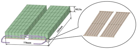
Figure 1.
Geometric model of battery module.
In order to improve the heat transfer enhancement in the battery cooling plate, various shapes of ribs are systematically arranged on the upper and lower surface of the cooling plate for the lithium-ion battery pack as depicted in Figure 2a. The rib shapes including a square rib, triangular rib, and semicircular rib on the cooling plate are explored in this study as shown in Figure 2b. In addition, the inclined ribs with rib angles of 75°, 60°, 45°, and 30° are also considered in this study as depicted in Figure 2c.
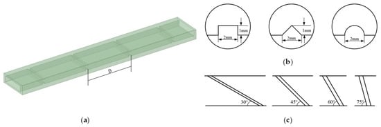
Figure 2.
Schematic diagram of (a) straight rib arrangement inside cooling channel, (b) rib shapes, (c) rib angles.
2.2. Heat Generation Model of Battery
The heat generation model of battery cells plays a crucial role in simulating the temperature distribution of the battery pack under various charging and discharging conditions. Generally, battery heat generation models can be divided into two categories: the electrochemical thermal battery model and the Bernardi heat generation model. The electrochemical thermal battery model requires detailed fundamental parameters of the battery, which is challenging to obtain in practical scenarios, thus limiting its application to some extent []. However, the Bernardi model only requires a subset of basic parameters to calculate the heat generation of the battery, making it widely used in both engineering applications and academic research []. In this study, the Bernardi model is adopted for the thermal simulation of the battery. The heat generation calculation formula of the Bernardi model is as follows:
This formula includes reversible heat, Ohmic heat, and polarization heat; , ,, and represent the current (A), open-circuit voltage (V), terminal voltage (V), and battery temperature (°C) during charging and discharging, respectively; is the temperature coefficient []. The right side of the equation includes Joule heat and electrochemical reaction heat. Since the value of the electrochemical reaction heat is relatively small and can be neglected, the formula is simplified []:
where represents the internal resistance of the battery (Ω). According to the data provided by the company, the capacity of the battery cell is 130 Ah, with charge/discharge cut-off voltages of 3.4 V/2.7 V, respectively. Under the same state of charge (SOC), low temperatures will increase the internal resistance of the battery. This is because at lower temperatures, the electrolyte conductivity decreases, the electrochemical reaction rate decreases, and some electrode materials may undergo structural changes or deactivation, resulting in decreased performance of the electrode materials and thus an increase in battery internal resistance []. The open-circuit voltage (OCV) of the battery () varies with SOC obtained through offline OCV testing [], as shown in Figure 3a. Meanwhile, the battery internal resistance used in this study was obtained through HPPC experimental testing [], and the variation in battery internal resistance with SOC under different test environment temperatures is shown in Figure 3b.
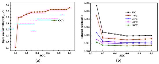
Figure 3.
Battery characteristics’ curve: (a) open-circuit voltage variation with SOC, (b) internal resistance variation with SOC at different ambient temperatures.
2.3. Governing Equations
The structure of lithium-ion batteries is complex and involves internal electrochemical reactions. When conducting CFD numerical simulations, simplification is necessary to reduce computational complexity; otherwise, it will increase the number of grids and complexity, leading to significantly longer simulation times and difficulty in achieving convergence of the results. Therefore, in order to reduce computational complexity and improve efficiency, the battery is treated as a uniform volume heat source, and internal thermal convection and radiation are not considered; the thermal capacity of the battery is constant and independent of time; the heat generated by the battery is radially transferred to the surroundings through direct contact. The energy equation during the charging and discharging processes of the battery is as follows:
where , , and represent the density, specific heat capacity, and temperature of the battery, respectively; and represent the thermal conductivity along the length and width directions of the battery, respectively, and represents the thermal conductivity along the thickness direction; represents the heat generated by the battery calculated by Equation (1). The mass conservation law, momentum conservation law, and energy conservation law of the liquid coolant are formulated as follows []:
where , , , , , , and represent the density, velocity vector, static pressure, dynamic viscosity, specific heat capacity, thermal conductivity, and temperature of the coolant, respectively. Equation (4) represents mass conservation, indicating that within a given period, the mass flow rate through any given surface is equal to the rate of change of mass within the fluid, meaning that mass only transforms between different substances. Equation (5) represents momentum conservation, revealing the distribution of velocity and pressure fields during fluid flow, describing their motion trajectories under different conditions. Equation (6) represents energy conservation, indicating that energy of an object neither increases nor decreases out of thin air, revealing the law of energy conversion and transfer in the fluid.
2.4. Boundary Conditions and Mesh Independent Study
In this study, a cooling plate with smooth channels is installed beneath the battery module to cool the battery pack. Additionally, a 1.5 mm thick thermal conductive silicone pad is placed between the battery cells and the cooling plate to reduce contact thermal resistance and enhance heat transfer. A 2.5 mm spacer is inserted between the batteries to prevent direct contact and mitigate the risk of short circuits. Moreover, the resilience of the spacer aids in absorbing vibrations and impacts during the operation of electric vehicles, thereby improving the stability and lifespan of the battery module. The thermal physical properties of the battery pack system are presented in Table 1.

Table 1.
Thermal Material Properties.
The simplified battery pack model was meshed for CFD numerical calculations. Since the fluid mesh significantly affects simulation accuracy, the fluid region was refined with a mesh size of 0.5 mm. Polyhedral meshes were selected for their ability to accurately describe complex geometries and improve convergence of the computational results. The meshing results of the battery module are shown in Figure 4a, with a total of 26.82 million cells. Figure 4b shows the local grid details at the interface between the battery, thermal pad, and cooling plate.
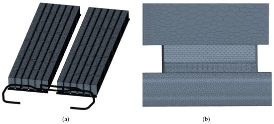
Figure 4.
The battery pack: (a) overall mesh, (b) local mesh.
In this study, five grid schemes were selected with grid numbers ranging from 2.29 million to 18.06 million to perform grid independence verification. The maximum battery temperature and the pressure drop in the flow channels were used as monitoring parameters, and the results are shown in Figure 5. As depicted in the figure, it can be observed that changes in the grid number have a minimal impact on the maximum temperature, while the variation in the pressure drop is more significant. When the grid number reaches 8.71 million, both the maximum battery temperature and the pressure drop are independent regarding grid numbers. Therefore, a grid number of 8.71 million is adopted in the present study.
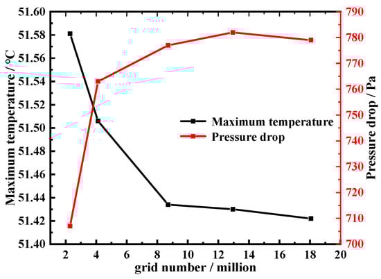
Figure 5.
Grid independence test.
2.5. Numerical Validation
The thermal performance of the battery pack of an electrical vehicle at high-speed climbing operating conditions in an environmental test chamber has been conducted and the tested experimental data have been adopted in this paper to validate the numerical model. In this experimental study, the ambient temperature of the battery pack is maintained as 40 ± 3 °C provided by a constant illumination intensity of 950 W/m2, and the relative humidity of the environmental test chamber is set as 40%, which provides the high-temperature environment in summer. The power output of the battery pack for an electrical vehicle at high-speed climbing operating conditions is 54.07 kW, and the initial SOC of the battery pack is 95%. For the battery pack cooling system, the liquid coolant with 50% ethylene glycol and 50% water in weight is adopted in the experimental test and the inlet temperature and mass flow rate of the liquid coolant are 25 °C and 10 L/min. The details of experimental tests can be found in our previous study in Ref. [] and are not repeated here.
In order to validate the numerical model of the battery pack, the boundary conditions adopted in this study are consistent with the experimental test as mentioned above. Figure 6 gives the numerical results of the maximum and the minimum temperature of the battery pack against corresponding experimental data. It should be noted that the difference between the maximum temperature and the minimum temperature in the experiments at the initial state of the experimental test has also been considered in our numerical model. It can be observed from Figure 6 that the prediction results of both the maximum and the minimum temperature of the battery pack are consistent with the experiments and the maximum prediction deviation in the numeral model is less than 5%. Thereby, the numerical model adopted in the present study is reasonable and convincible.
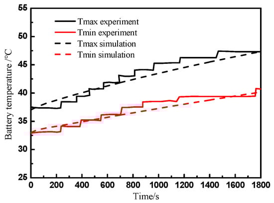
Figure 6.
Comparison of numeral results with experimental data [].
2.6. Parameter Definition
Fluid flow can be classified into laminar flow and turbulent flow based on the flow state. The criterion for determining the flow state is usually based on the Reynolds number (Re), calculated as shown in Equation (7).
where is the average velocity of the fluid cross-section (m/s), and represents the characteristic length of the cooling channel (m). When the cross-section of the channel is rectangular, the characteristic length in Equation (7) can be replaced by the equivalent diameter , which is calculated as follows:
where and represent the cross-sectional area (m2) and the perimeter (m) of the channel, respectively. The coolant used in the channels is an ethylene glycol solution. Since the Reynolds number for this coolant is less than 1000, a laminar flow model is employed in this study.
The dimensionless Nusselt number (Nu) performs the evaluation of natural convective heat transfer for a fluid flow []. It is defined as the ratio of convective to conductive heat transfer, which allows for an in-depth study of the mechanisms of fluid flow, convective heat transfer, and thermal conduction. A higher Nusselt number indicates stronger convective heat transfer, greater heat exchange capability, and higher heat transfer efficiency. The Nusselt number is calculated as follows:
According to the heat convection calculation formula [], the formula for calculating it is as follows:
where is the heat flux of the heat exchange wall; is the area of the heat exchange wall; is the temperature of the heat exchange wall; and is the volume-averaged temperature of the coolant. The formulas for calculating and are as follows:
where and are the average temperatures at the inlet and outlet of the coolant, respectively. The friction factor reflects the energy loss due to viscous resistance when the fluid flows inside the pipe. The calculation formula is shown in Equation (13). Its value is dimensionless and is positively correlated with the pressure drop of the coolant; thus, it can be used as an economic evaluation index. The calculation formula is as follows:
where is the pressure drop between the inlet and the outlet, and is the length of the flow channel.
This study comprehensively considers heat transfer performance and economic benefits, and proposes an evaluation index called the Heat Performance Enhancement Factor to measure the degree of improvement in thermal performance []. The calculation formula is shown in Equation (14). This factor is also dimensionless and indicates the improvement in heat transfer performance of the flow channel under the same energy consumption. It is used to evaluate the overall performance improvement in the proposed scheme compared to the original design in subsequent studies.
where and are the Nusselt numbers for the optimized channel and the smooth channel, respectively; and are the friction factors for the optimized channel and the smooth channel, respectively.
3. Results and Discussion
3.1. Effect of Straight Rib Shape on Heat Transfer Performance
The impacts of the straight rib shapes including rectangular ribs, semicircular ribs, and triangular ribs on the heat transfer performance of battery cooling plates have been analyzed in this paper based on the 2 C discharge rate operating condition of the battery pack. The results are shown in Figure 7. As the mass flow rate increases, different rib shapes exhibit different trends. At low mass flow rates, triangular ribs show the highest thermal performance improvement. This is because the geometric shape of the triangular ribs induces stronger fluid disturbance and turbulence, thereby enhancing heat transfer. Additionally, the Nusselt number of the triangular ribs is close to that of the rectangular ribs, while the friction factor is lower, further promoting thermal performance improvement. With an increasing mass flow rate, rectangular ribs exhibit the best thermal performance at high mass flow rates. This is because the geometric shape of the rectangular ribs better suppresses fluid flow separation and vortex generation, reducing energy loss and flow resistance, and improving heat transfer efficiency. The thermal performance improvement in semicircular ribs is intermediate between rectangular and triangular ribs. Due to the relatively smooth geometric shape of the semicircular ribs, they generate less turbulence disturbance during fluid flow; thus, their heat transfer performance improvement is relatively low. Different rib shapes exhibit different thermal performance trends at varying mass flow rates. At low mass flow rates, triangular ribs achieve the highest thermal performance improvement through stronger fluid disturbance and lower friction factors. However, at high mass flow rates, rectangular ribs show the best thermal performance, while semicircular ribs fall between rectangular and triangular ribs.
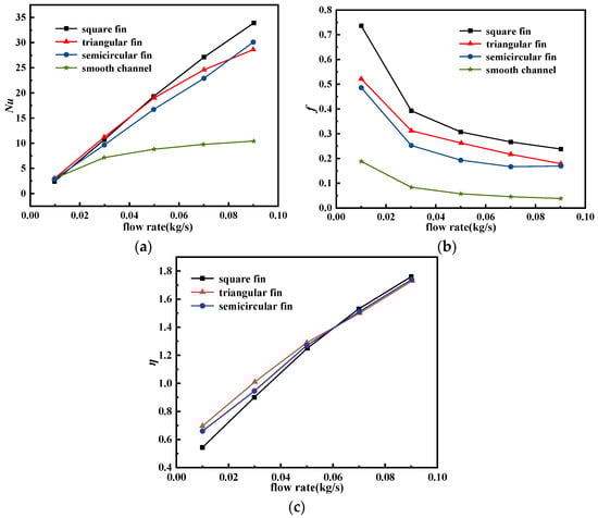
Figure 7.
Influence of different rib shapes on heat transfer performance: (a) Nusselt number, (b) friction factor, (c) thermal performance factor.
Figure 8 and Figure 9 present the temperature contour maps of the battery cross-section and the battery module, respectively, for four different configurations with an inlet mass flow rate of 0.09 kg/s. The results also confirm that the thermal performance of the cooling plate with ribs is significantly superior to that of the smooth channel. Furthermore, considering different cross-sectional shapes, the rectangular shape demonstrates the best heat transfer performance, followed by the semicircular shape, while the triangular shape exhibits relatively lower performance. Taking into account both heat transfer performance and economic benefits, subsequent investigations will adopt the rectangular ribbed structure as the fundamental model due to its more balanced performance.
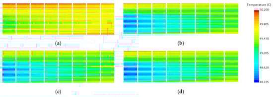
Figure 8.
Temperature contour plots of the mid-section of the battery under different straight rib cross-sectional shapes: (a) smooth channel, (b) triangular, (c) semicircular, (d) rectangular.
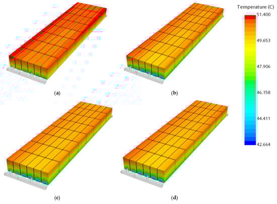
Figure 9.
Temperature contour plots of the battery module under different straight rib cross-sectional shapes: (a) smooth channel, (b) triangular, (c) semicircular, (d) rectangular.
Figure 10 depicts the velocity distribution of the fluid coolant in internal ribbed channels with different rib shapes for the battery cooling plate. It can be concluded that the velocity contour plot for the case of the square-ribbed channel is significantly higher than that of the other case, which implies that the case of the square-ribbed channel obtains the best heat transfer enhancement over the tested cases.
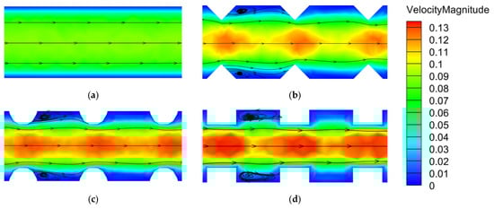
Figure 10.
Cross-sectional velocity distribution contour plots for different rib shapes: (a) smooth channel, (b) triangular, (c) semicircular, (d) rectangular.
3.2. Effect of Rib Angle on Heat Transfer Performance
Based on the comparison of simulation results for different cross-sectional shapes of straight ribs in the previous section, square ribs exhibiting better thermal performance at high mass flow rates were selected in this section to discuss the effect of the rib angle on the heat transfer performance of the cooling plate. With a specified spacing of 5 mm, the influence of the rib angle on the thermal performance of the cold plate was investigated. The simulation results are shown in Figure 11.
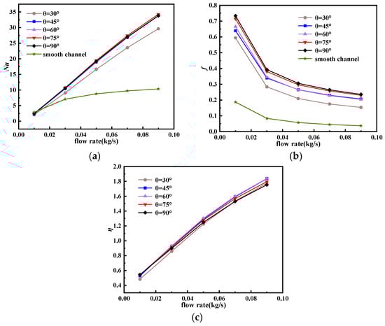
Figure 11.
Influence of different rib angles on heat transfer performance: (a) Nusselt number, (b) friction factor, and (c) thermal performance factor.
From Figure 11, it can be seen that the arrangement of ribs at various angles significantly increases both the Nusselt number and the friction factor compared to the straight channel. Except for the 30° ribs, the Nusselt numbers of the cold plates with ribs is insignificant. As the rib angle increases, the friction factor also gradually increases. Considering both heat transfer performance and pump power loss, Figure 11c shows that the cold plate with a 60° rib arrangement has a relatively higher thermal performance enhancement factor, indicating that this structure has the optimal heat transfer capability under the same pump power.
Figure 12 and Figure 13 show the temperature contour plots of the battery cross-section and battery module at different rib angles with an inlet mass flow rate of 0.09 kg/s. The results confirm the previous conclusions; i.e., the heat transfer performance of the ribbed cold plate is significantly better than that of the smooth channel. As the rib angle increases, the heat transfer performance improves. However, for a rib angle beyond 60 degrees, the minimum temperature continues to decrease insignificantly, and temperature uniformity is adversely affected. Therefore, considering both heat transfer performance and temperature uniformity, the 60° rib angle is adopted in this paper.
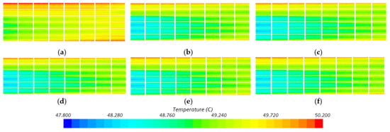
Figure 12.
Temperature contour plots of the battery cross-section at different rib angles: (a) smooth channel, (b) θ = 30°, (c) θ = 45°, (d) θ = 60°, (e) θ = 75°, (f) θ = 90°.
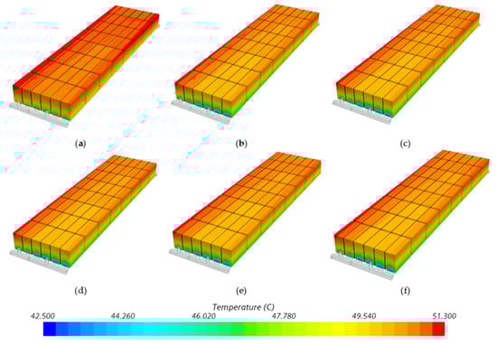
Figure 13.
Temperature contour plots of the battery module at different rib angles: (a) smooth channel, (b) θ = 30°, (c) θ = 45°, (d) θ = 60°, (e) θ = 75°, (f) θ = 90°.
Figure 14 illustrates the velocity contour plot for incline ribs in the cooling plate with different rib angles ranging from 30° to 90°. It can be observed that the cases of a rib angle of 60° to 90° obtain the highest velocity distribution as compared to the other cases. However, the pressure drops increase with the rise in the rib angle as shown in Figure 11b. Comparatively, the rib angle of 60° obtains the best heat transfer performance in battery cooling plates over the tested rib cases.
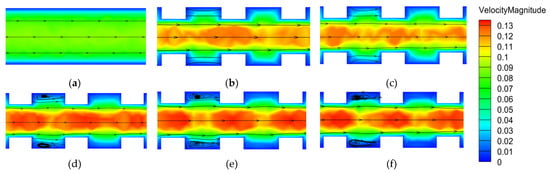
Figure 14.
Cross-sectional velocity distribution contour plots: (a) smooth channel, (b) θ = 30°, (c) θ = 45°, (d) θ = 60°, (e) θ = 75°, (f) θ = 90°.
3.3. Effect of Rib Spacing on Heat Transfer Performance
The effects of five different rib spacings (3 mm, 5 mm, 10 mm, 20 mm, and 40 mm) on the heat transfer characteristics of battery cooling plates with 60° square ribs based on a 2 C discharge rate of battery cells have been explored in this section. The simulation results are shown in Figure 15. It can be observed that as the mass flow rate of the cooling fluid increases, the difference between the Nusselt number of the ribbed cold plate and that of the smooth plate gradually increases, indicating that the ribbed cold plate has better heat transfer potential than the smooth plate. However, the presence of ribs increases the resistance during the flow of the cooling fluid. Moreover, as the flow rate increases, the impact of the cooling fluid on the ribs intensifies, amplifying the scale of the resistance effect. This is an inevitable side effect in most heat transfer enhancement techniques. While the presence of ribs enhances heat transfer performance with a smaller rib spacing under low flow rates, the increase in resistance is more significant. Conversely, under high flow rates, the situation is reversed. Therefore, the performance improvement factor decreases with decreasing rib spacing under low flow rates and increases with decreasing rib spacing under high flow rates. It is worth noting that as the rib spacing decreases, both the Nusselt number and the pressure drop increase, but after the rib spacing decreases to a certain value (D = 3 mm), both the Nusselt number and the pressure drop decrease.
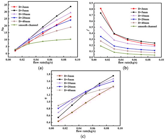
Figure 15.
Influence of different rib spacings on heat transfer performance: (a) Nusselt number, (b) friction factor, and (c) thermal performance factor.
Figure 16 and Figure 17 depict the temperature contour plots of the battery cross-section and battery module, respectively, for six different rib spacings at an inlet mass flow rate of 0.09 kg/s. It can be concluded from Figure 16 and Figure 17 that the heat transfer performance of the ribbed cold plate is significantly superior to that of the smooth channel. For different rib spacings at high flow rates, the heat transfer performance improves as the spacing increases. However, beyond a spacing of 5 mm, both the maximum temperature and temperature difference start to rise instead of decreasing. Therefore, considering both heat transfer performance and temperature uniformity, the rib spacing of 5 mm obtains the best thermal performance.
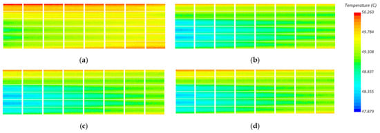
Figure 16.
Temperature contour plots of the battery cross-section for different rib spacings: (a) smooth channel, (b) D = 3 mm, (c) D = 5 mm, (d) D = 10 mm.
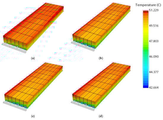
Figure 17.
Temperature contour plots of the battery module for different rib spacings: (a) smooth channel, (b) D = 3 mm, (c) D = 5 mm, (d) D = 10 mm.
Figure 18 shows the cross-sectional flow field information at a relatively stable state along the direction of coolant flow. Compared to the smooth channel (as shown in Figure 18a), the presence of ribs reduces the cross-sectional area of the channel, which increases the coolant flow velocity between the ribs and is consistent with the velocity distribution shown in the figure. After passing through the ribs, the fluid shifts laterally, forming secondary flows and vortices that disturb the thermal boundary layer at the wall. This allows the main cold fluid to come into direct contact with the wall, increasing the heat transfer temperature gradient and reducing thermal resistance at the wall. The disturbance also causes mixing between different fluid layers, enhancing heat exchange between the hot and cold fluids, thereby increasing the convective heat transfer coefficient and improving the heat transfer performance of the coolant. As the rib spacing decreases, fluid mixing becomes more frequent. However, if the rib spacing is sufficiently small, flow dead zones form between the ribs, where fluid does not pass through these areas a second time, reducing heat transfer and also decreasing pressure loss.
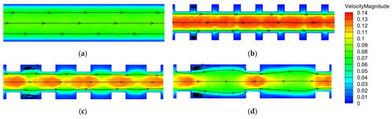
Figure 18.
Cross-sectional velocity contour plots: (a) smooth channel, (b) D = 3 mm, (c) D = 5 mm, (d) D = 10 mm.
3.4. Effect of Gradient Ribs on Heat Transfer Performance
Based on the investigation of the effects of different rib arrangements in the previous sections, this study selects three structures for comparison: structure a (smooth channel without ribs), structure b (rectangular rib configuration with 5 mm spacing and 60° orientation in a ribbed channel), and structure c (gradient ribbed channel).
Structure b is initially selected for its relatively better thermal performance compared to structure a. Simulations reveal that while the highest battery temperature with the ribbed structure b is reduced by 0.3 °C compared to the smooth channel structure a, the cross-sectional temperature difference within the battery cell increases by 0.357 °C. This increase in temperature difference is attributed to the uniform arrangement of ribs, which enhances the Nusselt number and heat transfer capability. However, this also causes the coolant to absorb more heat at the front end of the channel, resulting in a higher fluid temperature as it flows downstream. This reduces the temperature gradient with the cold plate, weakening the coolant’s ability to remove heat from the battery pack, leading to a higher temperature at the cooling channel outlet and an increased temperature difference between the inlet and outlet of the battery module. Addressing the temperature gradient along the flow direction of the coolant is crucial for improving the thermal uniformity of batteries.
To mitigate this issue, this study proposes a new design, structure c, featuring a gradient rib arrangement cold plate, as shown in Figure 19. This structure is divided into four zones along the flow channel, with 60° rectangular ribs arranged in a gradient. Zone 1 near the outlet has ribs with 5 mm spacing, Zone 2 has ribs spaced at three times that of the previous zone, and Zone 4 has no ribs. The rationale behind this gradient rib arrangement is to balance the heat absorption along the flow channel, thereby reducing the temperature gradient and improving thermal uniformity. The effectiveness of the gradient rib arrangement (structure c) is simulated and compared with structures a and b, as illustrated in Figure 20. The simulations demonstrate how the proposed gradient structure improves thermal performance and addresses the issues identified with the uniform rib arrangement in structure b.
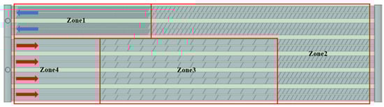
Figure 19.
Schematic diagram of gradient rib arrangement.
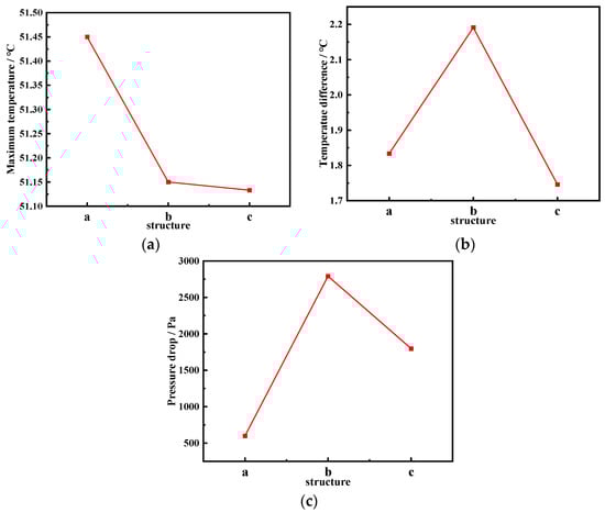
Figure 20.
Simulation results for different configurations: (a) maximum temperature, (b) temperature difference, (c) pressure drop.
From Figure 20, it can be observed that compared to structure b, the arrangement of gradient ribs in structure c reduces the temperature difference across the battery section by 0.445 °C, with a reduction of 20.3%, while keeping the maximum temperature of the battery module from increasing or even slightly decreasing. Additionally, the pressure drop decreases from 2792 Pa to 1798 Pa, with a reduction of 35.6%. Figure 21 and Figure 22 illustrate the temperature distribution across the battery module and the battery cell section under a 2 C discharge rate for the three different structures. It can be seen that structure b exhibits the lowest overall temperature, attributed to its wider distribution and denser arrangement of ribs, resulting in enhanced convective heat transfer due to higher Nusselt numbers, thereby improving the overall heat transfer performance. However, this also leads to a larger temperature gradient within the battery module, with a significant difference in temperature between the inlet and outlet regions of the flow channel above the battery cell section, validating the accuracy of the simulation results. The arrangement of gradient ribs in structure c reduces flow resistance in the upstream region of the cooling plate channel, while strengthening heat transfer with the arrangement of ribs with the highest Nusselt numbers downstream, aiming to lower the temperature in the region with the highest temperature and improve temperature uniformity across the battery module.
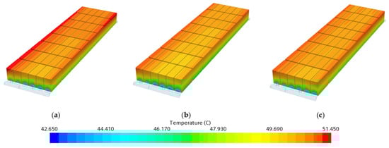
Figure 21.
Battery module temperature contour plots: (a) structure a, (b) structure b, (c) structure c.
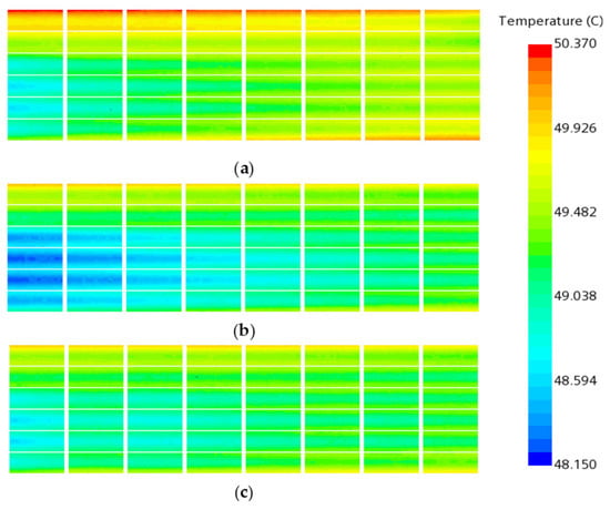
Figure 22.
Cross-sectional temperature contour plots of the battery cell: (a) structure a, (b) structure b, (c) structure c.
3.5. Analysis of Heat Transfer Performance under Real Working Conditions
3.5.1. Heat Transfer Performance in High-Speed Climbing Conditions
Based on the study in the previous section, Section 3.4, the thermal performance of the improved configuration of gradient ribs and the original smooth channel is compared in this section. The comparison results are shown in Figure 23. Compared to the smooth channel structure, the gradient ribbed structure reduced the maximum temperature by approximately 0.9 °C and the temperature difference by 0.8 °C, effectively enhancing heat dissipation performance and temperature uniformity.
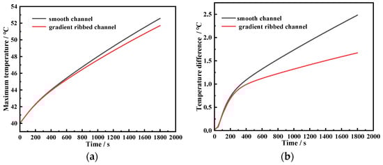
Figure 23.
Simulation comparison results: (a) maximum temperature of battery module, (b) cross-sectional temperature difference within battery cell.
Figure 24 and Figure 25 show the temperature contour plots of the battery module and the temperature distribution within the battery cell cross-section under high-speed climbing conditions. From Figure 24a and Figure 25a, it can be seen that the temperature of the battery increases continuously along the flow direction of the channel, with higher temperatures observed in the battery near the outlet of the cold plate. This is an inherent defect of the straight channel structure. By contrast, the temperature uniformity for the case of the gradient ribbed channel is significantly improved as compared to the case of the smooth straight channel as shown in Figure 24 and Figure 25.
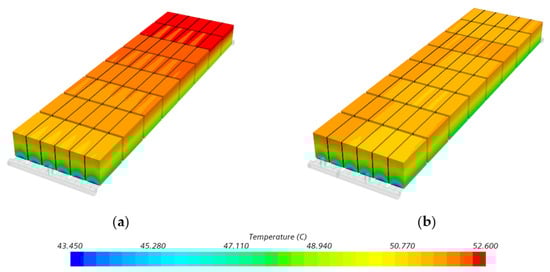
Figure 24.
Temperature contour plots of the battery module: (a) smooth channel, (b) gradient ribbed channel.
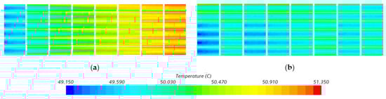
Figure 25.
Cross-sectional temperature contour plots of the battery cell: (a) smooth channel, (b) gradient ribbed channel.
3.5.2. Heat Transfer Performance in Low-Temperature Heating Conditions
As is well known, the driving range of electric vehicles and the lifespan of the power batteries at low temperatures are severely affected by temperature, especially at low-temperature operating conditions. This study adopts an actual engineering application of electric vehicles’ operating condition in a low-ambient-temperature environment. It simulates the condition of heating the battery pack from −30 °C to 5 °C in a low-ambient-temperature environment, evaluating the heating performance of the battery pack based on the temperature rise rate and the cross-sectional temperature difference of the battery pack at the end of heating.
In this study, the heating performance for both the improved model (gradient rib channel) and the smooth channel is evaluated at a coolant inlet temperature of 45 °C. The results of temperature difference for the heating condition are shown in Figure 26. It can be seen from Figure 26 that the trend of a temperature rise in the battery pack varying with heating time for both the gradient rib channel and the smooth channel is similar, but the temperature difference in the straight channel reached 6.6 °C at the end of heating time, exceeding the engineering safety limit of a maximum temperature difference of 5 °C. In contrast, the temperature difference for the gradient rib channel increased rapidly at the early stage of the heating process, but gradually decreased for heating time beyond 400 s. At the end of heating time, the temperature difference in the optimized structure was 2.2 °C, significantly lower than that of the straight channel, maintaining the battery module within the safe temperature difference range. This phenomenon can be explained by examining the temperature distribution in the battery module and the cross-section of the battery cell under the heating conditions of the two cooling plate structures, as shown in Figure 27 and Figure 28. It is evidently observed that from Figure 27a and Figure 28a that the entire battery module exhibits a significant temperature gradient along the flow direction in the straight channel cooling plate, resulting in a large temperature difference between the inlet and the outlet of the cooling plate. Comparatively, the gradient rib arrangement effectively decreases the temperature difference of both the battery pack and the cooling plate as shown in Figure 27b and Figure 28b, which implies that the gradient rib configuration significantly enhances the heat transfer downstream of the cooling plate, resulting in diminishing the whole temperature difference of the battery pack.
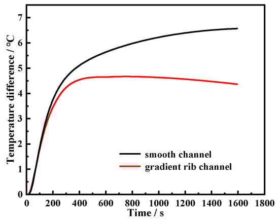
Figure 26.
Temperature difference variation curves over time for the gradient ribbed channel and smooth channel.
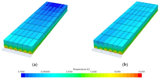
Figure 27.
Temperature contour plots of the battery module: (a) smooth channel, (b) improved structure.
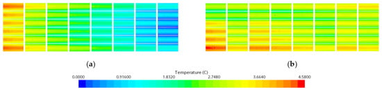
Figure 28.
Temperature contour plots of the battery cell cross-section: (a) smooth channel, (b) gradient ribbed channel.
The temperature of the cooling liquid is a crucial parameter affecting the heating performance of the battery module. Therefore, this section also discusses the influence of four cooling liquid temperatures ranging from 25 °C to 55 °C on the thermal performance of the battery module, covering the actual temperature range of the heating fluid in the battery thermal management cycle system. The simulation results are shown in Figure 29, indicating that as the temperature of the heating fluid increases, the time required to heat the battery to 5 °C decreases, but the temperature uniformity deteriorates. For instance, the battery module heated by the fluid at 55 °C reaches the target temperature of 5 °C by a heating time of 1254 s, which is faster than that heated by the fluid at 25 °C with an increased temperature difference of 2.525 °C.
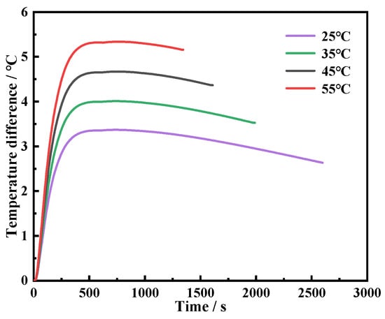
Figure 29.
The variation curves of battery temperature difference over time at different temperatures.
4. Conclusions
This study investigates the thermal performance of a battery pack for an electric vehicle. The cooling plate of the battery pack added by various rib configurations in the smooth channel has been considered in this study. The effects of rib shapes, rib angles, rib spacing, and gradient rib configurations on the flow and heat transfer of the cooling plate as well as the thermal performance of the battery pack have been discussed and analyzed in detail. In addition, the thermal performance of the battery pack for an improved rib configuration of the cooling plate at real electric vehicle operation conditions for both the high-temperature cooling and low-temperature heating conditions is also considered in this study. The primary objective is to provide valuable insights and recommendations for optimizing cooling plate designs in power battery systems. The corresponding results are summarized as follows:
- (1)
- The square-ribbed channel obtains the best heat transfer performance in the battery pack cooling plate among all the investigated rib shape configurations. In addition, the square rib configuration with a rib spacing of 5 mm and rib angle of 60° exhibits the best heat transfer performance over the tested rib cases. Compared with the original smooth channel cooling plate, the rib-added configuration of the cooling plate obviously reduces the maximum temperature of the battery pack and improves the battery pack temperature uniformity.
- (2)
- At low mass flow rates, the triangular ribs exhibit the greatest improvement in thermal performance, while at high mass flow rates, the rectangular ribs achieve the most significant enhancement. The semicircular ribs demonstrate thermal performance that falls between the two. An increase in the rib angle noticeably enhances the heat transfer of the cooling plate with increased pressure drops. In addition, the heat transfer enhancement in the cooling plate decreases with the rise in rib spacing except for the case of rib spacing at 3 mm. Meanwhile, the pressure drops decrease with the increase in rib spacing.
- (3)
- The gradient rib configuration in a battery cooling plate is proposed in this study. The thermal performance of the battery pack coupled with the gradient rib cooling plate is significantly improved as compared to the smooth straight cooling plate for both the high-speed climbing operating condition and low-temperature heating condition. The maximum temperature and temperature difference of the battery pack for the case of gradient rib configuration compared with the smooth channel at the high-speed climbing operating condition are reduced by 0.9 °C and 0.8 °C, respectively, while the maximum temperature difference for the case of gradient rib configuration at the low-temperature operating condition is decreased by 2.2 °C as compared to the smooth channel.
- (4)
- The inlet temperature of the fluid coolant for the battery pack with the gradient rib cooling plate at the low-temperature heating operating condition is also explored in this paper. Increasing the inlet temperature of the fluid coolant can obviously shrink the heating time of the battery pack with the maximum temperature difference of 5.3 °C at an inlet temperature of 55 °C.
Author Contributions
Conceptualization, J.W. and D.L.; methodology, H.S.; software, C.L.; validation, H.W.; formal analysis, Y.J.; investigation, J.W.; resources, J.Z. and T.G.; data curation, H.Y.; writing—original draft preparation, J.W.; writing—review and editing, J.W. and D.L.; supervision, J.Z.; project administration, J.Z. and T.G.; funding acquisition, J.Z. All authors have read and agreed to the published version of the manuscript.
Funding
The research was funded by the Science and Technology Research Program of Chongqing Municipal Education Commission (Grant No. KJQN202201120).
Data Availability Statement
The original contributions presented in the study are included in the article, further inquiries can be directed to the corresponding author.
Conflicts of Interest
Authors Jiadian Wang and Haonan Sha were employed by the company The 703 Research Institute of China Shipbuilding Industry Corporation, Hang Wu and Yanjun Jiang were employed by the company Chongqing Tsingshan Industria Co., Ltd. The remaining authors declare that the research was conducted in the absence of any commercial or financial relationships that could be construed as a potential conflict of interest.
References
- Lei, S.; Xin, S.; Liu, S. Separate and Integrated Thermal Management Solutions for Electric Vehicles: A Review. J. Power Sources 2022, 550, 232133. [Google Scholar] [CrossRef]
- Shahjalal, M.; Shams, T.; Islam, M.E.; Alam, W.; Modak, M.; Hossain, S.B.; Ramadesigan, V.; Ahmed, M.R.; Ahmed, H.; Iqbal, A. A Review of Thermal Management for Li-Ion Batteries: Prospects, Challenges, and Issues. J. Energy Storage 2021, 39, 102518. [Google Scholar] [CrossRef]
- Bandhauer, T.M.; Garimella, S.; Fuller, T.F. A Critical Review of Thermal Issues in Lithium. J. Electrochem. Soc. 2011, 158, R1–R25. [Google Scholar] [CrossRef]
- Ma, S.; Jiang, M.; Tao, P.; Song, C.; Wu, J.; Wang, J.; Deng, T.; Shang, W. Temperature Effect and Thermal Impact in Lithium-Ion Batteries: A Review. Prog. Nat. Sci. Mater. Int. 2018, 28, 653–666. [Google Scholar] [CrossRef]
- Pesaran, A.A. Battery Thermal Management in Ev and Hevs: Issues and Solutions. Battery Man 2001, 43, 34–49. [Google Scholar]
- Jiaqiang, E.; Yue, M.; Chen, J.; Zhu, H.; Deng, Y.; Zhu, Y.; Zhang, F.; Wen, M.; Zhang, B.; Kang, S. Effects of the Different Air Cooling Strategies on Cooling Performance of a Lithium-Ion Battery Module with Baffle. Appl. Therm. Eng. 2018, 144, 231–241. [Google Scholar]
- Yates, M.; Akrami, M.; Javadi, A.A. Analysing the Performance of Liquid Cooling Designs in Cylindrical Lithium-Ion Batteries. J. Energy Storage 2021, 33, 100913. [Google Scholar] [CrossRef]
- Fan, Y.; Wang, Z.; Xiong, X.; Zhu, J.; Gao, Q.; Wang, H.; Wu, H. Novel Concept Design of Low Energy Hybrid Battery Thermal Management System Using Pcm and Multistage Tesla Valve Liquid Cooling. Appl. Therm. Eng. 2023, 220, 119680. [Google Scholar] [CrossRef]
- Al-Zareer, M.; Dincer, I.; Rosen, M.A. Heat and Mass Transfer Modeling and Assessment of a New Battery Cooling System. Int. J. Heat Mass Transf. 2018, 126, 765–778. [Google Scholar] [CrossRef]
- Babaharra, O.; Choukairy, K.; Faraji, H.; Hamdaoui, S. Improved Heating Floor Thermal Performance by Adding Pcm Microcapsules Enhanced by Single and Hybrid Nanoparticles. Heat Transf. 2023, 52, 3817–3838. [Google Scholar] [CrossRef]
- Yu, L.; Li, Y. A Flexible-Possibilistic Stochastic Programming Method for Planning Municipal-Scale Energy System through Introducing Renewable Energies and Electric Vehicles. J. Clean. Prod. 2019, 207, 772–787. [Google Scholar] [CrossRef]
- Yang, N.; Zhang, X.; Li, G.; Hua, D. Assessment of the Forced Air-Cooling Performance for Cylindrical Lithium-Ion Battery Packs: A Comparative Analysis between Aligned and Staggered Cell Arrangements. Appl. Therm. Eng. 2015, 80, 55–65. [Google Scholar] [CrossRef]
- Tong, W.; Somasundaram, K.; Birgersson, E.; Mujumdar, A.S.; Yap, C. Thermo-Electrochemical Model for Forced Convection Air Cooling of a Lithium-Ion Battery Module. Appl. Therm. Eng. 2016, 99, 672–682. [Google Scholar] [CrossRef]
- Chen, K.; Song, M.; Wei, W.; Wang, S. Structure Optimization of Parallel Air-Cooled Battery Thermal Management System with U-Type Flow for Cooling Efficiency Improvement. Energy 2018, 145, 603–613. [Google Scholar] [CrossRef]
- Yan, Z. Characteristics and Optimization Design of Forced Air Cooling for Lithium-ion Batteries of Electric Vehicles. Master’s Thesis, Beijing University of Technology, Beijing, China, 2021. [Google Scholar]
- Hasan, H.A.; Togun, H.; Abed, A.M.; Biswas, N.; Mohammed, H.I. Thermal Performance Assessment for an Array of Cylindrical Lithium-Ion Battery Cells Using an Air-Cooling System. Appl. Energy 2023, 346, 121354. [Google Scholar] [CrossRef]
- Oyewola, O.M.; Awonusi, A.A.; Ismail, O.S. Design Optimization of Air-Cooled Li-Ion Battery Thermal Management System with Step-Like Divergence Plenum for Electric Vehicles. Alex. Eng. J. 2023, 71, 631–644. [Google Scholar] [CrossRef]
- De Vita, A.; Maheshwari, A.; Destro, M.; Santarelli, M.; Carello, M. Transient Thermal Analysis of a Lithium-Ion Battery Pack Comparing Different Cooling Solutions for Automotive Applications. Appl. Energy 2017, 206, 101–112. [Google Scholar] [CrossRef]
- Zhu, Y.; Cui, X.; Han, H.; Sun, S. The Study on the Difference of the Start-up and Heat-Transfer Performance of the Pulsating Heat Pipe with Water—Acetone Mixtures. Int. J. Heat Mass Transf. 2014, 77, 834–842. [Google Scholar] [CrossRef]
- Mali, V.; Saxena, R.; Kumar, K.; Kalam, A.; Tripathi, B. Review on Battery Thermal Management Systems for Energy-Efficient Electric Vehicles. Renew. Sustain. Energy Rev. 2021, 151, 111611. [Google Scholar] [CrossRef]
- Murali, G.; Sravya, G.S.N.; Jaya, J.; Vamsi, V.N. A Review on Hybrid Thermal Management of Battery Packs and It’s Cooling Performance by Enhanced Pcm. Renew. Sustain. Energy Rev. 2021, 150, 111513. [Google Scholar] [CrossRef]
- Karimi, G.; Li, X. Thermal Management of Lithium-Ion Batteries for Electric Vehicles. Int. J. Energy Res. 2013, 37, 13–24. [Google Scholar] [CrossRef]
- Luo, Y.; Luo, B.; Lang, C. Research on Direct Contact Liquid Cooling Method for Lithium-ion Power Battery Pack. Automot. Eng. 2016, 38, 909–914. [Google Scholar]
- Shang, Z.; Qi, H.; Liu, X.; Ouyang, C.; Wang, Y. Structural Optimization of Lithium-Ion Battery for Improving Thermal Performance Based on a Liquid Cooling System. Int. J. Heat Mass Transf. 2019, 130, 33–41. [Google Scholar] [CrossRef]
- Zhang, T.; Gao, Q.; Wang, G.; Gu, Y.; Wang, Y.; Bao, W.; Zhang, D. Investigation on the Promotion of Temperature Uniformity for the Designed Battery Pack with Liquid Flow in Cooling Process. Appl. Therm. Eng. 2017, 116, 655–662. [Google Scholar] [CrossRef]
- Xu, S. Analysis of Heat Dissipation and Pressure Loss in Serpentine Liquid Cooling Plate Battery Thermal Management System. Master’s Thesis, Hunan University, Hunan, China, 2017. [Google Scholar]
- Wang, Y. Design and Optimization Research on Surrounding Liquid Cooling Heat Dissipation Structure of Lithium-ion Battery Module for Electric Vehicles. Master’s Thesis, Jiangsu University, Jiangsu, China, 2021. [Google Scholar]
- Angani, A.; Kim, H.-W.; Hwang, M.-H.; Kim, E.; Kim, K.-M.; Cha, H.-R. A Comparison between Zig-Zag Plated Hybrid Parallel Pipe and Liquid Cooling Battery Thermal Management Systems for Lithium-Ion Battery Module. Appl. Therm. Eng. 2023, 219, 119599. [Google Scholar] [CrossRef]
- Subhedar, D.; Chauhan, K.V.; Panchal, S.; Bais, A. Numerical Investigation of Performance for Liquid-Cooled Cylindrical Electrical Vehicle Battery Pack Using Al2O3/Eg-Water Nano Coolant. Mater. Today Proc. 2023. [Google Scholar] [CrossRef]
- Chen, S.; Bao, N.; Garg, A.; Peng, X.; Gao, L. A Fast Charging—Cooling Coupled Scheduling Method for a Liquid Cooling-Based Thermal Management System for Lithium-Ion Batteries. Engineering 2021, 7, 1165–1176. [Google Scholar] [CrossRef]
- Botte, G.G.; Subramanian, V.R.; White, R.E. Mathematical Modeling of Secondary Lithium Batteries. Electrochim. Acta 2000, 45, 2595–2609. [Google Scholar] [CrossRef]
- Bernardi, D.; Pawlikowski, E.; Newman, J. A General Energy Balance for Battery Systems. J. Electrochem. Soc. 1985, 132, 5–12. [Google Scholar] [CrossRef]
- Li, Z.; Huang, J.; Liaw, B.Y.; Zhang, J. On State-of-Charge Determination for Lithium-Ion Batteries. J. Power Sources 2017, 348, 281–301. [Google Scholar] [CrossRef]
- Liang, G.; Li, J.; He, J.; Tian, J.; Chen, X.; Chen, L. Numerical Investigation on a Unitization-Based Thermal Management for Cylindrical Lithium-Ion Batteries. Energy Rep. 2022, 8, 4608–4621. [Google Scholar] [CrossRef]
- Ma, R.; Ma, X.; Ye, Y.; Wu, Y. Comparison of the Mixed Flow and Heat Transfer Characteristics in the Evaporator of a Vapor Compression Heat Pump in Normal Gravity and Microgravity. Int. J. Heat Mass Transf. 2021, 172, 121170. [Google Scholar] [CrossRef]
- Zheng, Y.; Ouyang, M.; Lu, L.; Li, J. Understanding Aging Mechanisms in Lithium-Ion Battery Packs: From Cell Capacity Loss to Pack Capacity Evolution. J. Power Sources 2015, 278, 287–295. [Google Scholar] [CrossRef]
- Bai, Y.; Li, L.; Li, Y.; Chen, G.; Zhao, H.; Wang, Z.; Wu, C.; Ma, H.; Wang, X.; Cui, H.; et al. Reversible and Irreversible Heat Generation of Nca/Si–C Pouch Cell During Electrochemical Energy-Storage Process. J. Energy Chem. 2019, 29, 95–102. [Google Scholar] [CrossRef]
- Wu, C.; Ni, J.; Shi, X.; Huang, R. A New Design of Cooling Plate for Liquid-Cooled Battery Thermal Management System with Variable Heat Transfer Path. Appl. Therm. Eng. 2024, 239, 122107. [Google Scholar] [CrossRef]
- Zeng, J.; Fu, H.; Feng, S.; Lai, C.; Song, J.; Fu, L.; Chen, H.; Gao, T. Numerical Analysis on Thermal Management Performance of Lithium-Ion Battery Pack with Liquid Cooling. In Proceedings of the International Conference on Energy Storage and Intelligent Vehicles, online, 3–4 December 2022. [Google Scholar]
- Faraji, H.; Teggar, M.; Arshad, A.; Arıcı, M.; Berra, E.M.; Choukairy, K. Lattice Boltzmann Simulation of Natural Convection Heat Transfer Phenomenon for Thermal Management of Multiple Electronic Components. Therm. Sci. Eng. Prog. 2023, 45, 102126. [Google Scholar] [CrossRef]
- Yang, S.M.; Tao, W. Heat Transfer Science; Higher Education Press: Beijing, China, 2006. [Google Scholar]
- Jiang, W.; Zhao, J.; Rao, Z. Heat Transfer Performance Enhancement of Liquid Cold Plate Based on Mini V-Shaped Rib for Battery Thermal Management. Appl. Therm. Eng. 2021, 189, 116729. [Google Scholar] [CrossRef]
Disclaimer/Publisher’s Note: The statements, opinions and data contained in all publications are solely those of the individual author(s) and contributor(s) and not of MDPI and/or the editor(s). MDPI and/or the editor(s) disclaim responsibility for any injury to people or property resulting from any ideas, methods, instructions or products referred to in the content. |
© 2024 by the authors. Licensee MDPI, Basel, Switzerland. This article is an open access article distributed under the terms and conditions of the Creative Commons Attribution (CC BY) license (https://creativecommons.org/licenses/by/4.0/).