Article

A Stability Control Method to Maintain Synchronization Stability of Wind Generation under Weak Grid

1
The School of Electric Power Engineering, South China University of Technology, Guangzhou 510640, China
2
State Key Laboratory of HVDC, Electric Power Research Institute, China Southern Power Grid Co., Ltd., Guangzhou 510663, China
3
The School of Automation Science and Engineering, South China University of Technology, Guangzhou 510640, China
*
Author to whom correspondence should be addressed.
Energies 2024, 17(17), 4450; https://doi.org/10.3390/en17174450
Submission received: 18 June 2024 / Revised: 21 August 2024 / Accepted: 1 September 2024 / Published: 5 September 2024
(This article belongs to the Topic Clean and Low Carbon Energy, 2nd Volume)

Abstract

:
When wind generation systems operate under weak grid conditions, synchronization stability issues may arise, restricting the wind farms’ power transfer capacity. This paper aims to address these challenges on the grid side. Firstly, a clear exposition of the coupling mechanism between the grid-connected inverters (GCI) of wind generations and the weak grid is provided. Then, an equivalent parallel compensation method integrated into the PLL to enhance synchronization stability is proposed. The method changes the reference of the PLL and equivalently parallels the virtual resistance with the grid impedance, which alters the strength of the grid. It reshapes the inverter qq-axis impedance at the impedance level. And the proper design of the virtual resistance will enhance the system’s stability without compromising the dynamic performance of PLL. In addition, the proposed method is robust to the parameter changes of the grid-connected system and the grid impedance measurement error. Experimental results are presented to validate the effectiveness of the compensation method.

1. Introduction

The development of wind generation has gained significant momentum as a solution to environmental pollution in recent years. Given the decentralized nature of wind resources, power plants are often situated in remote locales. And it relies on GCI to access the conventional grid.
However, employing PLL as synchronization units in wind generation systems can potentially introduce synchronization instability problems, particularly under weak grid conditions [1]. The sub-synchronous resonance (SSR) was observed in the Xinjiang Type-IV wind generation plant [2].
The impedance-based stability criterion combined with the generalized Nyquist criterion (GNC) is extensively adopted to address the synchronization instability issues [3]. The dq-frame impedance model of GCI is established in [4], and the qq-axis negative resistance is considered as the fundamental factor contributing to synchronization instability. Ref. [5] analyzes the PLL feedforward effect on the control of GCI and concludes that the PLL current feedforward effect has a more adverse impact on system stability. Ref. [6] simplifies the MIMO impedance model to the SISO model to assess the impacts on the synchronization stability of PLL, current control, voltage feedforward, and DC voltage controller. Additionally, ref. [7] derives a SISO impedance model related to the synchronization loop, with PLL loop shaping employed to enhance stability. In [8], a d-axis current error is feedforward to current control to damp the resonance based on the steady-state relationship.
The stability improvement methods are proposed for both the motor side [9] and the grid side. On the grid side, the widely adopted method is a feedforward method to reshape the impedance characteristic [10].
Since the PLL is pivotal for synchronization, several studies have focused on modifying the PLL [11,12]. Recent efforts have predominantly focused on changing the PLL input. Ref. [13] enhances the passivity of a GCI by multiplying the output impedance phase regulator of normalized magnitude with the phase-locked loop inputs. Ref. [14] introduces a compensation frame to achieve current control by phase lag compensation, which is employed in PLL. By modifying the PLL input, ref. [15] introduces a series resistance in the grid impedance to increase damping in the studied system. However, this method entails a complex impedance model. Ref. [16] analogous to the back electromotive force observer in DC motor control, the input ofthe PLL is readjusted by state estimation.
Some of the literature achieves oscillation suppression by employing novel control methods. The literature [17] points out that the grid-forming control has more stability under weak grids compared to the grid-following control, but it will be a risk of instability under strong grids. Ref. [18] controls the GCI without adopting PLL implemented by the voltage-modulated direct power control. And it can also be utilized in weak grids by employing a band-pass filter [19]. The adaptive dual-mode control is suggested for oscillation suppression, i.e., current source mode under a weak grid and voltage source mode under a strong grid [20]. Ref. [21] proposes a grid voltage feedforward control strategy based on multi-objective objective constraint to broaden the adaptation range of the system to the grid impedance.
In addition, ref. [22] analyzes the stability range of PLL parameters under weak grid, finding suitable parameters by iterative adjustment method to enhance the power transfer capability. Ref. [23] concludes that the guideline that the PLL bandwidth should not exceed one-tenth of the current loop may not be applicable under weak grid. Ref. [24] proposes a control parameter design method considering the fluctuation of the grid impedance to improve the dynamic stability under weak grid. The supplementary damping controllers, such as TCSC, have also been adopted to damp the SSR of wind generations [25].
However, stability enhancement methods based on optimizing system parameters sacrifice the bandwidth of the PLL or current control, increasing the coupling between the current control and PLL. The supplementary damping controllers are limited in their promotion by their high cost and complex operation control modes. Therefore, optimizing the grid-side or motor-side control system for the studied system is more appropriate.
But the current study of the coupling mechanism of a grid-connected system is still incomplete, resulting in the existing stability control strategies mainly relying on feedforward compensation based on the q-axis voltage. And the compensation term is complicated. When the grid impedance changes and the parameter changes during the actual operation of the system, it brings new challenges for the stability control methods. Hence, there is a pressing need to introduce novel stability control methods derived from the coupling mechanism of grid-connected systems.
This article proposes an equivalent parallel resistance compensation method on the grid side employed in the PLL, which is based on comprehending the root of instability. The highlights are summarized as below:
(a)
A clear exposition of the coupling mechanism among the PLL, weak grid, and current control is provided, laying the groundwork for forthcoming stability enhancement techniques.
(b)
An equivalent parallel resistance compensation method integrated into PLL is proposed to improve synchronization stability. It reshapes the qq-axis impedance and will not decrease the dynamic performance of PLL with a proper design of virtual resistance.
(c)
The compensation method demonstrates robustness against system parameter variations and grid impedance measurement errors.
The subsequent sections are structured as follows: Section 2 derives the investigated system’s impedance model and analyzes the coupling mechanism between the PLL, weak grid, and current control. Section 3 presents the proposed equivalent parallel resistance compensation method, including its design and performance analysis. Section 4 conducts the experimental verification. Section 5 concludes and outlines future work.

2. Impedance Model and Stability Analysis of the Grid-Connected System

2.1. Description and Model of System

Because the dynamic of the DC capacitor is slow, the motor side and the grid side are decoupled in type-IV wind generation. Thus, the rotor side is represented by DC-source. The topology is shown in Figure 1. Filter inductor Lf is utilized to filter the GCI output voltage Viabc to PCC voltage Vabc. By controlling the dq-component ( i d c , i q c ) of the current Iabc and synchronizing with the voltage of PCC, the grid-following control based on PLL can be achieved. Table 1 lists the introduction and the value of system parameters. SCR is usually used to define the grid strength, and the equation of SCR can be expressed as:
S C R = 3 V g 2 Z g S
where Vg is the grid voltage magnitude, Zg is the grid impedance, and S is the rated capacity of the grid-connected system. When SCR > 3, it is considered a strong grid; 2 < SCR < 3, it is considered a weak grid; and SCR < 2, it is considered a very weak grid.
The input of the PLL is Vabc rather than Vgabc under the weak grid case. This leads to distinct system frames and control frames. The dq-component of variables in the system and control frame are equal in steady state, namely x d q s = x d q c , where the control frame and the system frame are designated with “c” and ”s”.
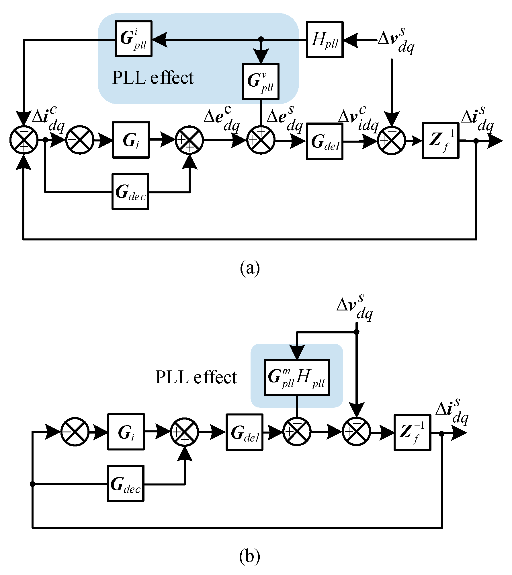
Figure 2a illustrates the control block of the GCI with PLL effects. The relationship between the current ∆idq and modulated voltage ∆edq in different frames is as follows [8]:
Δ i d q c = Δ i d q s + 0 I q r e f 0 I d r e f G p l l i ( s ) H p l l ( s ) Δ v d q s
Δ e d q c = Δ e d q s + 0 V i q 0 V i d G p l l v ( s ) H p l l ( s ) Δ v d q s
G p l l i ( s ) and G p l l v ( s ) represent the PLL feedforward effects on current and modulated voltage. Idqref and Vidq denote the steady-state values [8]. Hpll(s) describes the relationship from the Δ v q s to the ∆θ:
H p l l ( s ) = G p l l ( s ) s + V d s G p l l ( s )
G p l l ( s ) = k p p l l + k i p l l s 1
Gi(s) represents the matrix of current control, Gdec(s) is the matrix of decoupling term, and I is the unit matrix.
G i ( s ) = G i ( s ) I = k p i + k i i s 1 I
G d e c ( s ) = 0 ω L f ω L f 0
The impedance matrix Zf corresponds to the inverter side filter inductance Lf and is expressed as:
Z f = s L f ω L f ω L f s L f
The time delay matrix Gdel(s) accounts for the digital control delay, with Tdel = 1.5 Ts. It is defined as:
G d e l ( s ) = ( 1 0.5 T d e l s 1 + 0.5 T d e l s ) I
Figure 2a can be further converted to Figure 2b, where G p l l m ( s ) can be given by:
G p l l m = G d e l ( ( G i G d e c ) G p l l i G p l l v )
Considering that the capacitor branch has a more significant influence on the high-frequency dynamics, while the oscillation of the studied system primarily occurs at frequencies less than 200 Hz, the filter capacitor branch is simplified. Consequently, the expression for the inverter impedance Zout can be obtained as:
Z o u t = Z o u t , d d Z o u t , d d Z o u t , q d Z o u t , q q = ( Z f + ( G i G d e c ) G d e l ) ( I + G p l l m H p l l ) 1
The grid impedance, denoted as Zg, can be obtained as follows:
Z g = s L g ω L g ω L g s L g

2.2. Stability and the Coupling Mechanism Analysis

Based on (8), the Zout can be presented in a more intuitive way:
Z o u t = ( I ( Z f + ( G i G d e c ) G d e l ) 1 Z p l a n t 1 + G p l l m H p l l ( Z f + ( G i G d e c ) G d e l ) 1 Z p l l m 1 ) 1
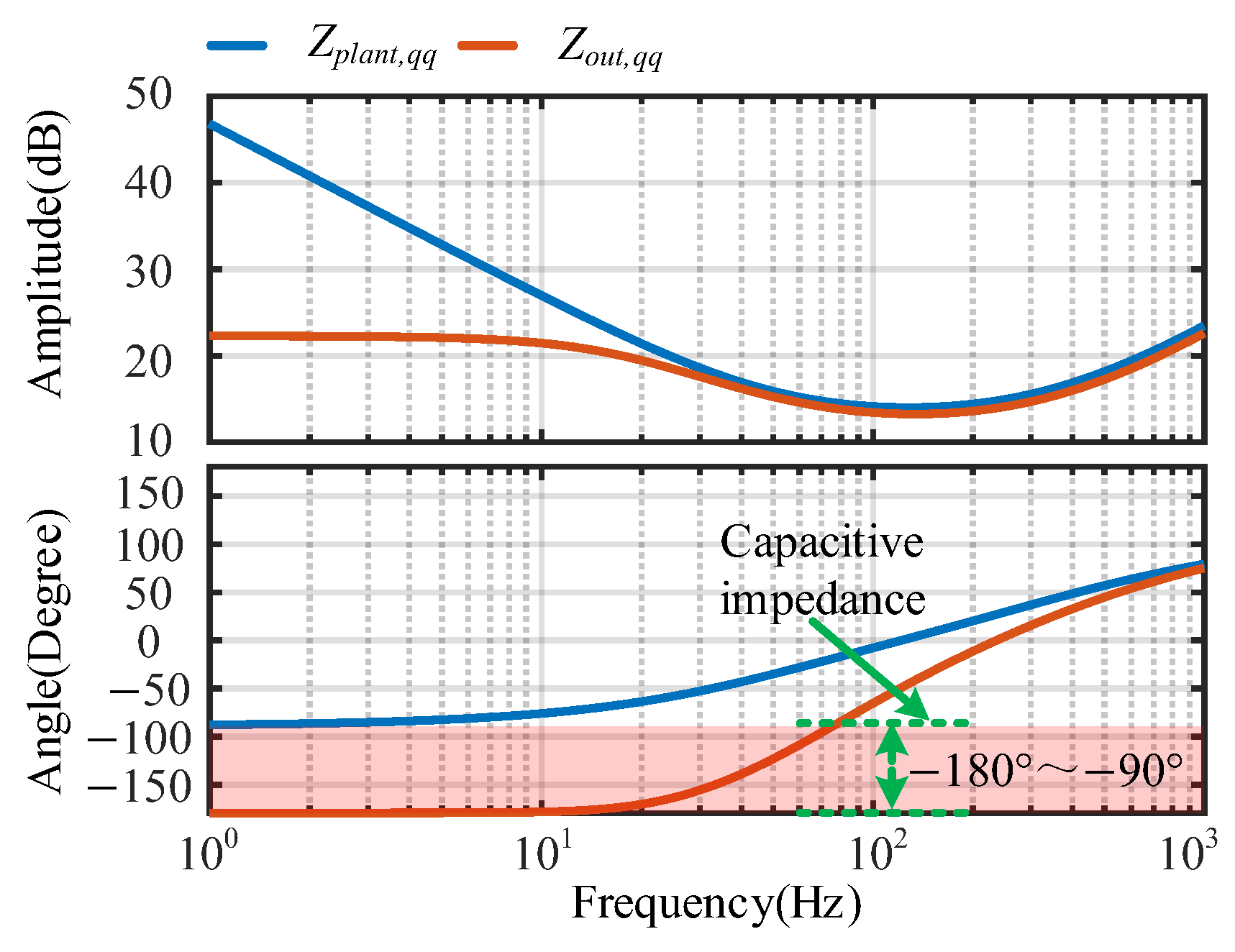
Zout denotes the impedance of the GCI incorporating the PLL feedforward effect, while Zplant refers to the GCI impedance when the PLL feedforward path is not taken into account. Z p l l m ( s ) represents the impedance formulated by the feedforward effect.
Figure 3 shows the GNC plot of the L p ( s ) = Z g Z p l a n t 1 when Lg = 16 mH and the L o ( s ) = Z g Z o u t 1 when Lg = 9 mH, Lg = 16 mH. The eigen-traces λ1p, λ2p correspond to Lp(s), and the eigen-traces λ1o, λ2o correspond to Lo(s).
As depicted in Figure 3, when the PLL effect is not taken into account, and Lg = 16 mH, the λ1p, λ2p do not intersect (−1, j0), where the stable operation can be maintained. When taking into account the PLL effect, it is evident that the system remains stable when Lg = 9 mH, whereas instability arises when Lg = 16 mH. Therefore, the system’s stability is primarily influenced by both the PLL and the grid impedance. The coupling between the weak grid and the PLL will be explored in the following.
The Bode plot of the GCI impedance in qq-axis when considering PLL effects and not considering PLL effects is shown in Figure 4. It can be deduced that Zout,qq exhibits capacitive impedance characteristics in qq-axis due to the PLL effect, which may couple with a weak grid and further contribute to instability. Thus, the PLL affects the stability of the studied system via current control by the feedforward effect.
Further exploration of the coupling between the weak grid and PLL will be conducted subsequently. The steady-state relationship between the v d q s , v g d q s and Zg can be formulated as:
v d q s = v g d q s + Z g i d q s
Linearizing Formula (14) and assuming negligible variation in the grid voltage v g d q s at steady state:
Δ v d q s = Z g Δ i d q s
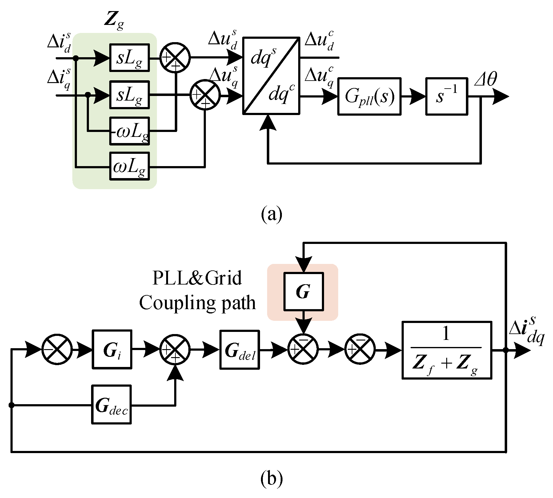
Based on Formula (15), the small signal model of the PLL can be represented in Figure 5a. This depiction clearly reveals the interconnection between the Zg and PLL. PLL further feedforwards the current control, resulting in the formulation of the qq-axis capacitive impedance area.
Figure 5b further provides an intuitive representation of the coupling, where G denotes the coupling term, which can be mathematically obtained as:
G = G p l l m H p l l Z g

3. Analysis and Design of Equivalent Parallel Compensation Method

3.1. Analysis of the Equivalent Parallel Compensation Method

When a virtual resistance is parallel with Zg, it leads to a modification in the reference of the PLL, consequently changing the coupling method. It results in a reduction in the coupling degree between the qq-axis capacitive impedance of the GCI and the inductive weak grid. Meanwhile, the damping of the studied system can be improved by the virtual resistance.
To achieve the stability control of the grid-connected system, an equivalent parallel compensation method integrated into PLL is proposed. The Zg in complex space is expressed as follows [26]:
Z g = ( s + j ω 1 ) L g
Assuming the virtual resistance Rv is parallel with Zg, the expression for the grid impedance Zg,com after parallel connection can be expressed as:
Z g , c o m = R v ( s + j ω 1 ) L m g + R v G v r , d q ( s + j ω 1 ) L g
where Lmg is the grid impedance value measured by the impedance measuring device, G can be expressed as another expression:
G ( s ) = G p l l m ( s ) H p l l ( s ) G v r , d q H p l l ( s ) H p l l , c o m ( s + j ω 1 ) L g
The specific implementation of the virtual resistance will be discussed below. Due to the difficulty of paralleling the resistance with the grid impedance in practical applications, it can modify Hpll to Hpll,com, namely modify the input of the PLL as shown in Formula (18). Where Gvr,dq in dq domain can be converted to Gvr,αβ in αβ domain:
G v r , α β ( s ) = e j θ G v r , d q ( s + j ω ) e j θ = R v s L m g + R v
According to Formula (19), when multiplying the transfer function Gvr,αβ with the PLL input in the αβ domain, the transfer function of Hpll becomes Hpll,com, which equivalently parallels the virtual resistance Rv with the grid impedance. The equivalent parallel resistance compensation method alters the coupling method in the studied system. Adopting the equivalent parallel resistance compensation method, the coupling degree will decrease, which theoretically improves the damping of the studied system.
Expanding on the above analysis, the modified PLL structure is shown in Figure 6. Here, Gvr,αβ = Gvr,αβ·I, and Gbpf = Gbpf·I. Gbpf is the band-pass filter aimed at preserving high-frequency characteristics and suppressing additional harmonics, expressed as:
G b p f ( s ) = 2 ξ ω 1 s s 2 + 2 ξ ω 1 s + ω 1 2
where ξ = 0.707, ω1 denotes the grid angular frequency. The introduction of Gvr,αβ changes the phase reference of PLL input, consequently altering the stable operational point. This leads to an undesirable reactive power. Therefore, the dq transform angle should be modified, formulated as:
T α β , d q = e j θ p l l , c o m = cos ( θ p l l , c o m ) sin ( θ p l l , c o m ) sin ( θ p l l , c o m ) cos ( θ p l l , c o m )
where θpll,com represents the corrected dq transform angle. Since the phase shift of the Gbpf is 0 at the fundamental frequency, θpll,com can be formulated as:
θ p l l , c o m = G v r , α β + θ p l l
Consequently, the impedance of GCI with the proposed compensation method can be modified as follows:
Z o u t , c o m = ( Z f + ( G i + G c o m ) G d e l ) ( I + G p l l m G v r , d q H p l l ) 1

3.2. Dynamic Performance of Compensation Method

The compensation method is utilized in the PLL without impacting the current tracking dynamic performance. The impact of the compensation method on PLL dynamic performance is assessed through MATLAB R2021b/Simulink.
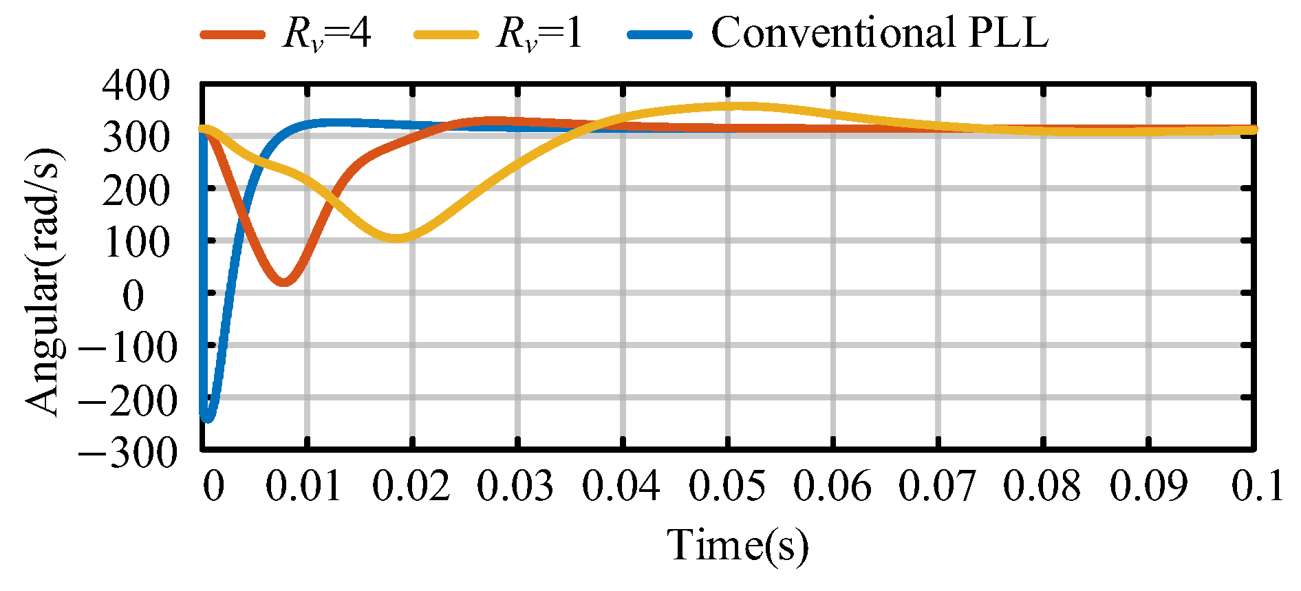
The dynamic performance of the frequency tracking for both the conventional PLL and the improved PLL with different values of Rv (Rv = 4 and Rv = 1) is illustrated in Figure 7. The improved PLL exhibits reduced undershoot compared to the conventional PLL. Furthermore, as Rv decreases, the undershoot is further minimized. Therefore, the improved PLL effectively mitigates the overshoot and undershoot observed in the conventional PLL.
The dynamic response time is slightly changed with the improved PLL when Rv = 4. But it will further decrease with improved PLL when Rv = 1. Thus, the Rv will not be designed too small for a better dynamic response time of the PLL.
Thus, with a well-designed Rv, the proposed compensation method effectively maintains the stability while preserving minimal impact on the dynamic performance of the frequency tracking. For the selection of Rv, if Rv is too high, the coupling degree cannot be decreased. Conversely, if Rv is set too low, it may adversely affect the dynamic performance of the PLL.

3.3. Design and Stability Analysis

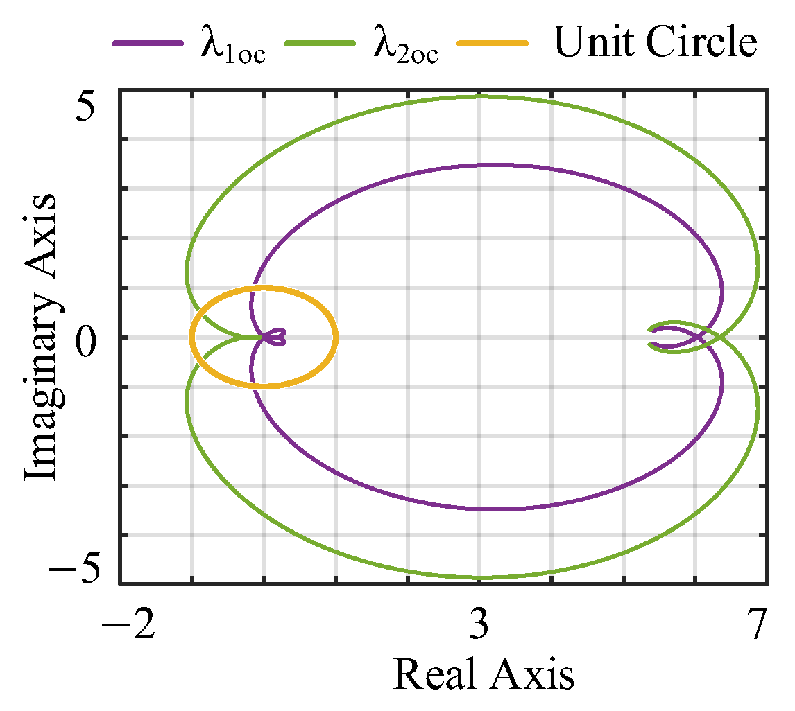
The stable range of the Rv is (0, 6) by employing the GNC to L c ( s ) = Z g Z o u t , c o m 1 . In this study, Rv is chosen as 2, as it offers appropriate damping while preserving the dynamic performance of the PLL. Figure 8 illustrates the GNC plot for Lg = 16 mH and Rv = 2. The GNC plot clearly indicates that (−1, j0) lies outside the λ1oc, λ2oc, indicating the stable operation of the interconnection system.
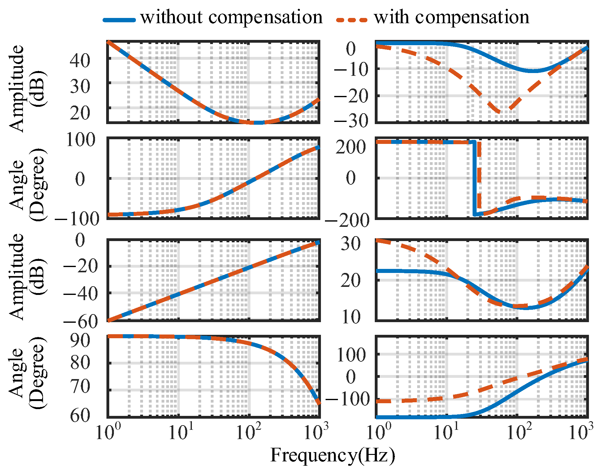
Figure 9 showcases the Bode plots of the GCI output impedance with and without compensation. Because the magnitude of the dq-axis impedance and the qd-axis impedance are relatively small, which can be omitted. The primary influence of the compensation method is located on the qq-axis impedance. With the implementation of the compensation method, the positive resistance area of qq-axis impedance expands. This signifies a reduction in the coupling degree between the PLL and the weak grid.

3.4. Robustness Analysis

The different operation modes of the grid-connected system may further decrease the stability. Factors such as the introduction of reactive power, increased PLL bandwidth, and grid impedance variations can destabilize the system. The errors of the estimated grid impedance Lmg of Gvr,dq also influence the effect of the compensation method. Therefore, it is imperative to conduct further analysis on the robustness of the proposed compensation method.
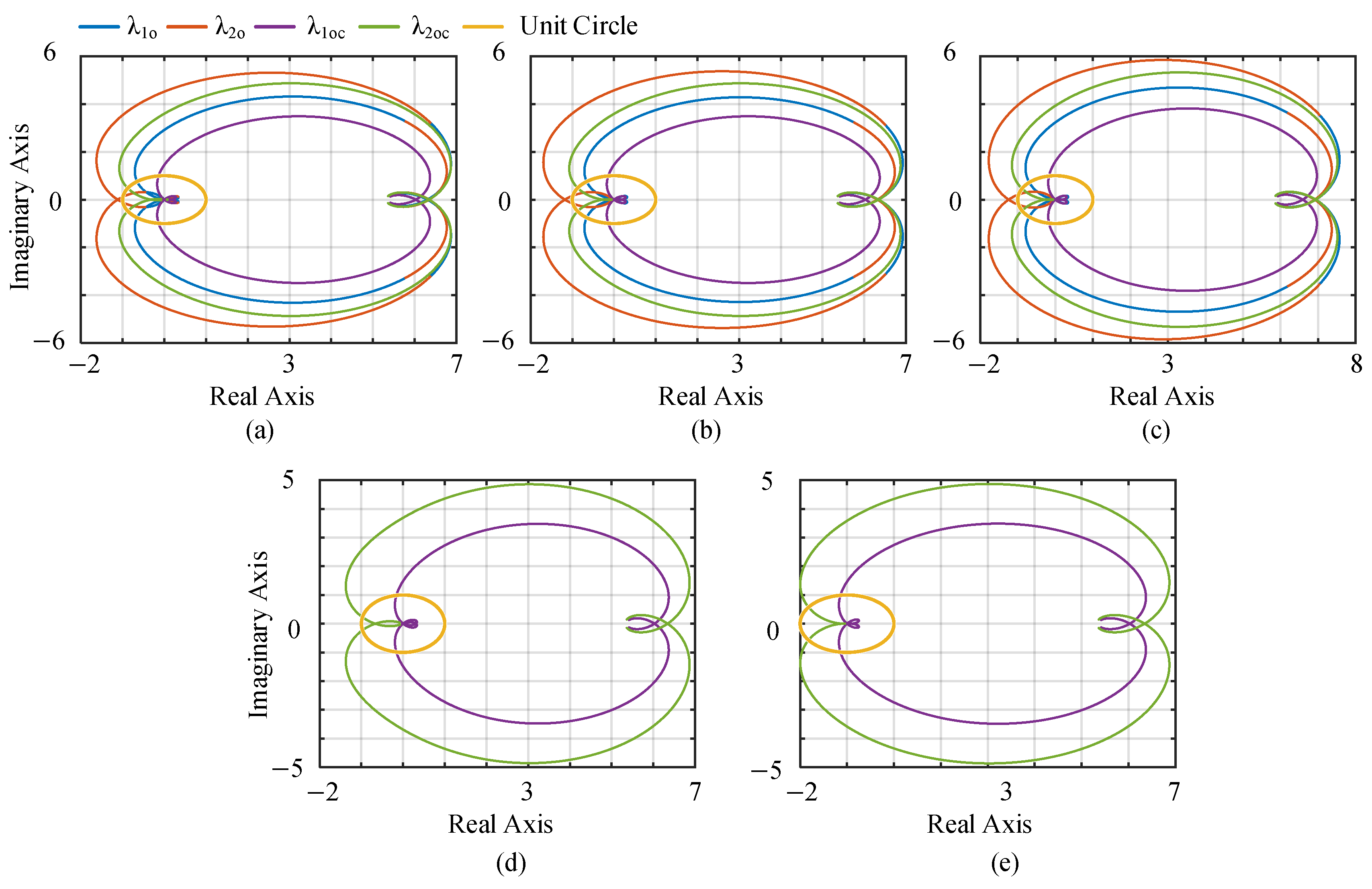
To validate the robustness of the equivalent parallel resistance compensation method, a series of test cases listed in Table 2 were investigated. Depicted in Figure 10, the grid-connected system exhibited instability under cases I, II, and III. However, with the equivalent parallel resistance compensation method, stability was achieved in the grid-connected system for all three cases. It demonstrates the robustness of the equivalent parallel resistance compensation in accommodating reactive power introduction, fluctuations in PLL bandwidth, and grid impedance.
The proposed compensation method relies on obtaining grid impedance information. However, in practice, the unavoidable error of the grid impedance measurement device will lead to a deviation between the Lmg and the Lg. Therefore, it is necessary to analyze whether the equivalent parallel resistance compensation can achieve stable control when there are errors in grid impedance measurement.
The impacts of grid impedance estimation value Lmg, as revealed by Equation (19), on the compensation method can be inferred. Case IV and case V demonstrate that the compensation method can maintain stability even when the error in grid impedance measurement reaches −70% Lg and +160 Lg.
Compared with [27], the proposed compensation method is highly tolerated for grid impedance measurement errors. In addition, compared with the series resistance compensation method in [15], the impedance model of the proposed compensation method is not complicated.

4. Experiment and Simulation Verification

To verify the proposed equivalent parallel compensation method, a 2 kW grid-connected system is built up, employing a PM50CLA20 inverter made by Mitsubishi in Tokyo, Japan, and YXSPACE-SP2000 made by YANXU in Nanjing, China. Additionally, IT6535C serves as the DC power source, which is made by ITCH in Nanjing, China. And GCT33060 functions as the grid simulator, which is made by HANSUN in Shanghai, China. The weak grid is realized by connecting the inductor between the converter and grid simulator. The experimental setup is depicted in Figure 11.
Figure 12 shows the waveforms with different Lg. It can be observed from Figure 12b that when the SCR is switched from 4.6 to 2.59, the oscillations will occur. Notably, a positive-sequence frequency of 111.25 Hz and a negative-sequence frequency of 11.25 Hz are observed due to the mirror frequency effect, as illustrated in Figure 12c.
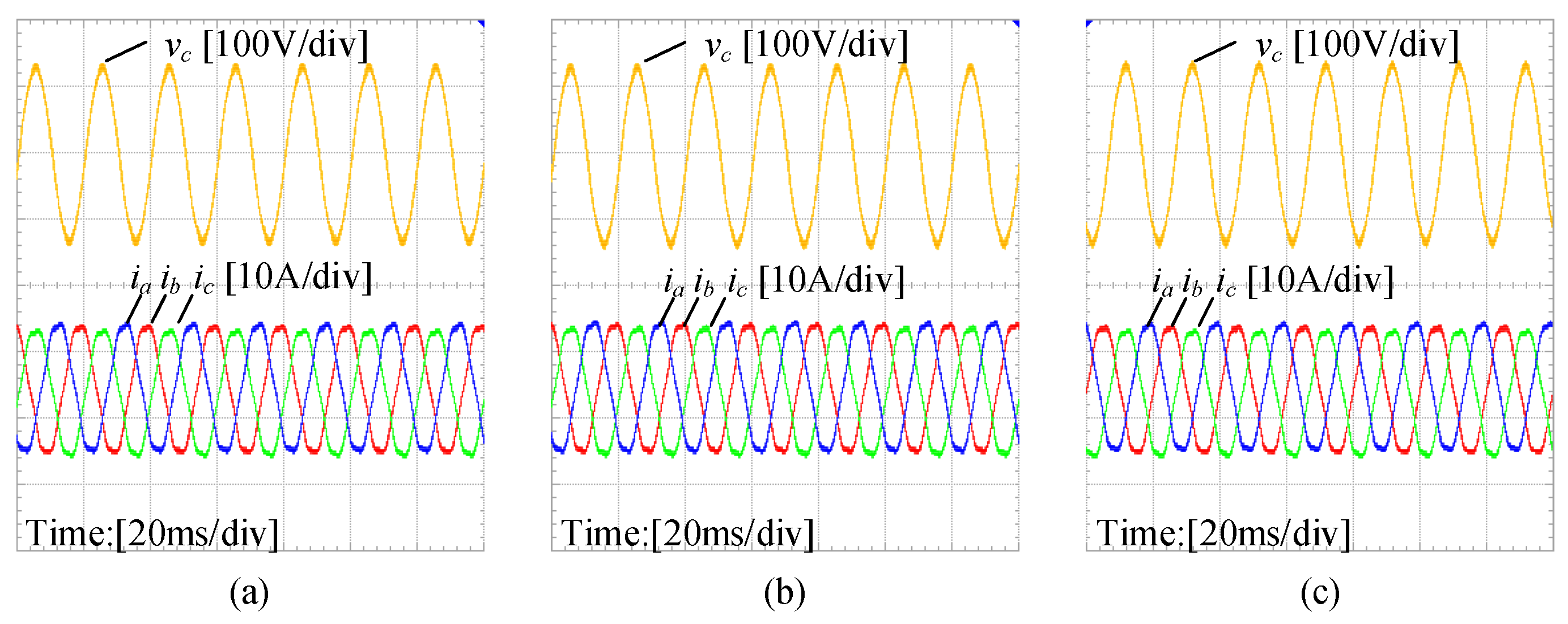
Figure 13 showcases the waveforms with the compensation method when Rv = 1, Rv = 2, Rv = 4. As depicted in Figure 13, the utilization of the compensation method reduces voltage and current distortion. Consequently, the studied system demonstrates stable operation with the utilization of the compensation method. Additionally, Figure 14 presents the fast Fourier transform (FFT) analysis of the current, indicating the damping of oscillation frequencies in all three cases.
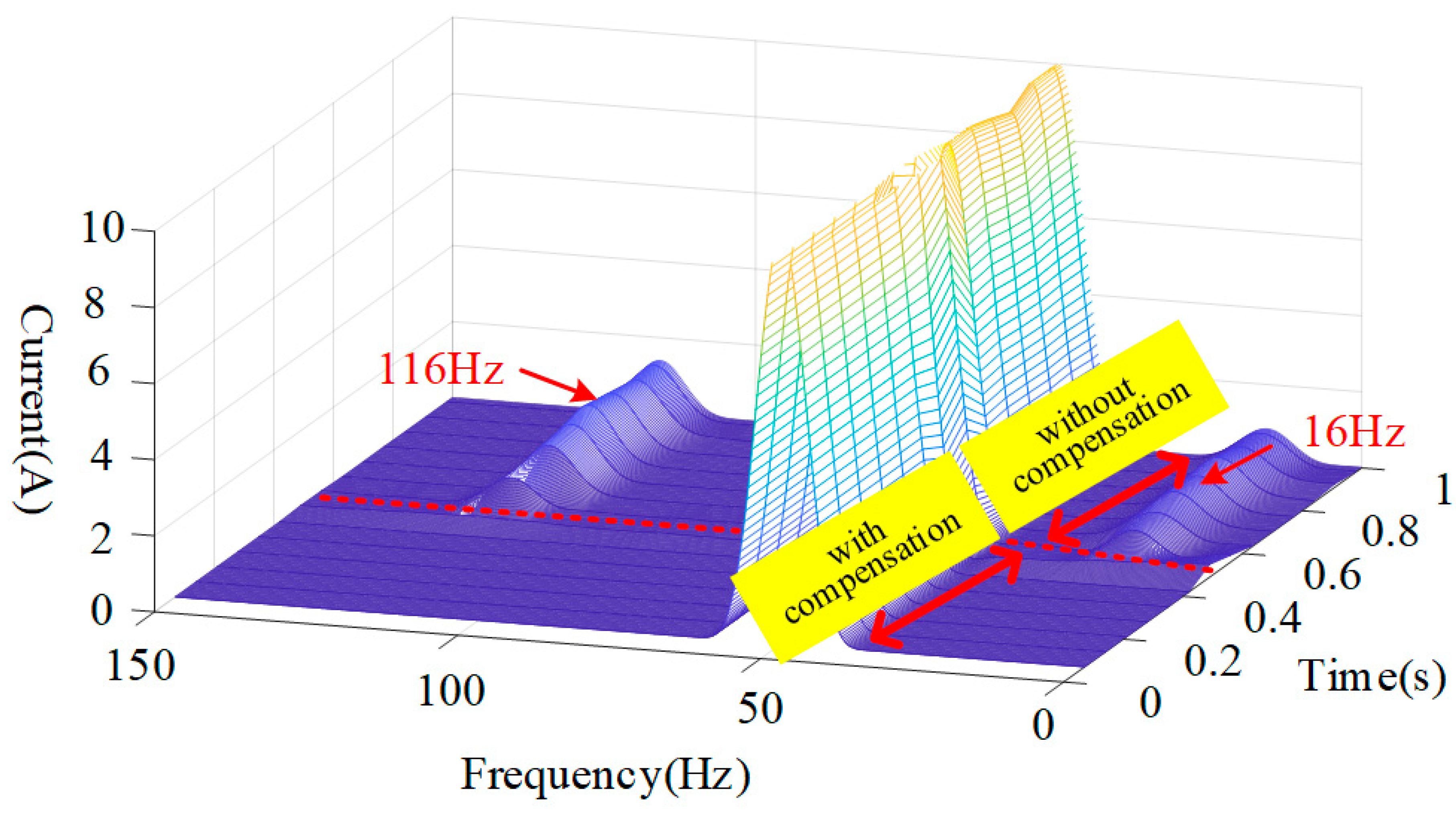
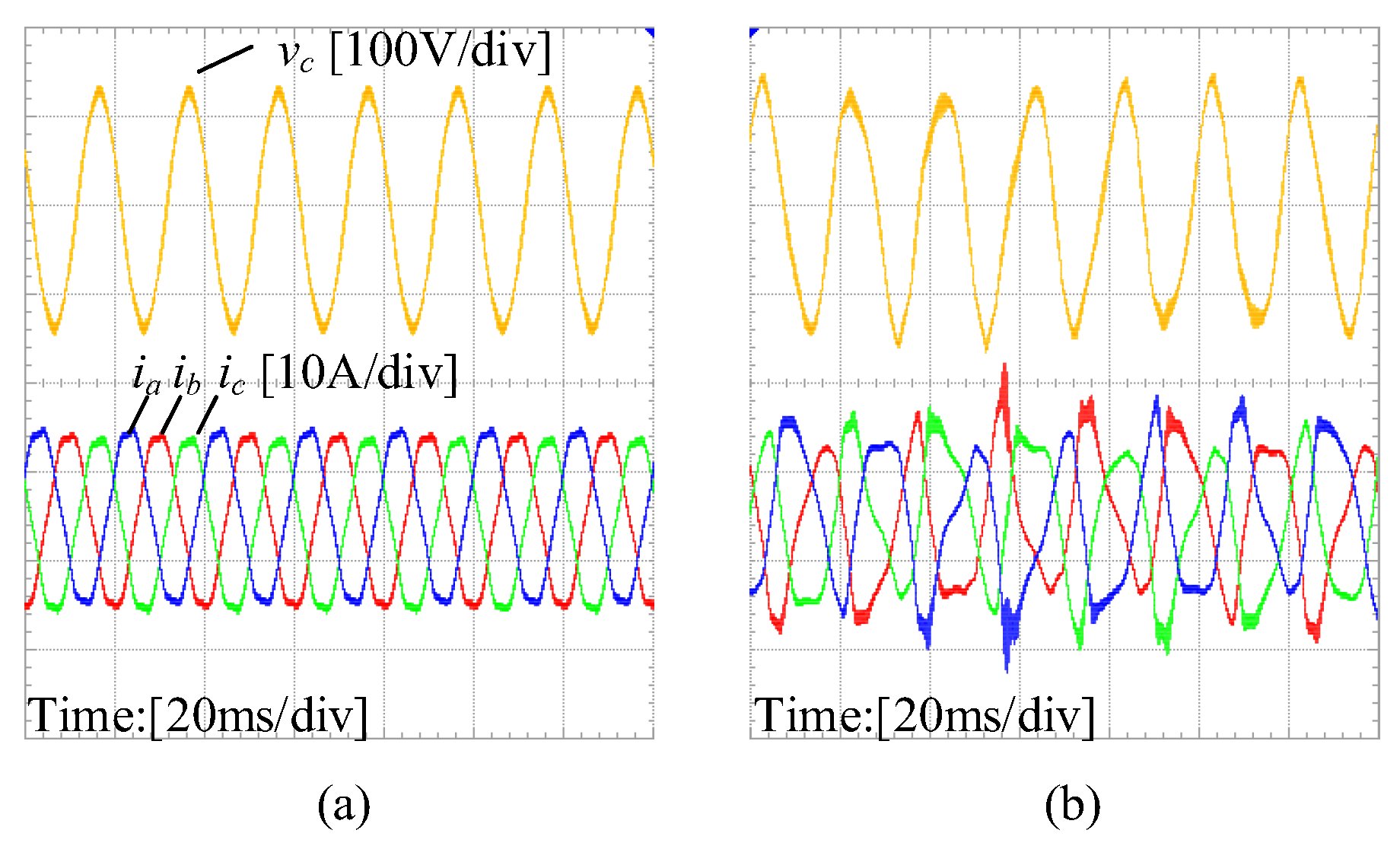
Figure 15 exhibits the waveforms with the compensation method for Rv = 2 under case I. The parameter variations of the studied system alter the oscillation frequency. From Figure 15a, when the compensation is not utilized, the investigated system experiences resonance. When the compensation method is adopted, the resonance can be mitigated. But the reference of PLL will be changed. Thus, there is a transient current overshoot and reactive power before the phase lock process, as depicted in Figure 15c. Figure 16 shows the damping process of ia, which is based on discrete Fourier transformation (DFT). The oscillation frequency of 16 Hz and 116 Hz will be attenuated after the adoption of the compensation method.
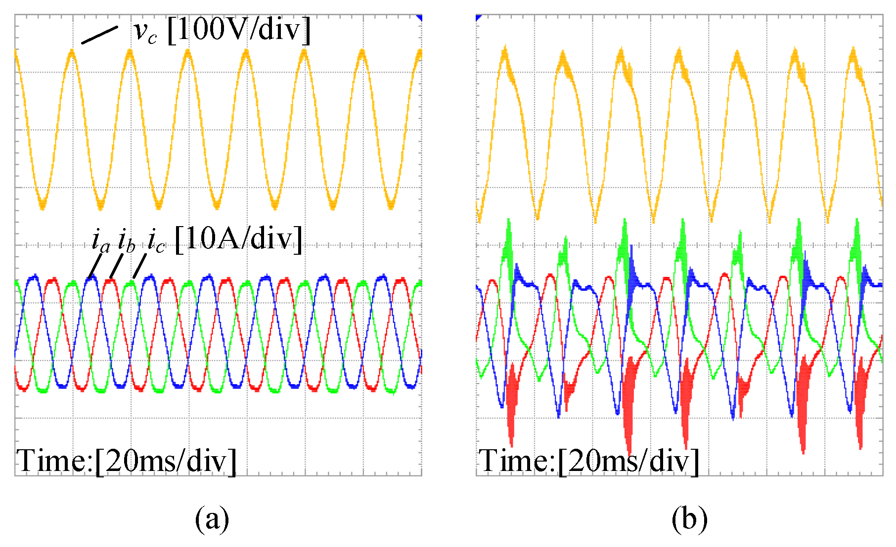
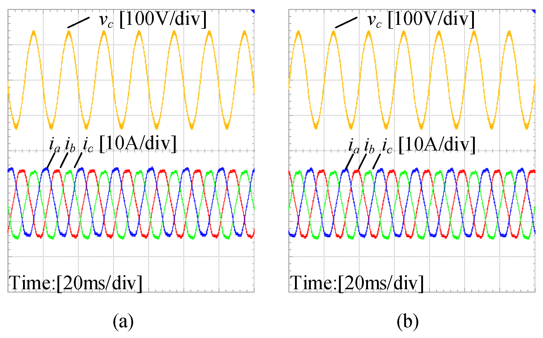
Figure 17 and Figure 18 present the waveforms when Rv = 2 under case II and case III. It can be deduced that the compensation method effectively dampens the resonance even when the oscillation frequency has shifted, indicating the robustness of the method against the introduction of reactive power, fluctuations in PLL bandwidth, and grid impedance. These experimental results provide further evidence of the effectiveness and robustness of the compensation method.
Figure 19 illustrates the waveforms of when Rv = 2 under case IV and case V. Given Formula (23), the error in grid impedance measurement does not affect the effectiveness of the phase correction. In addition, the error of grid impedance measurement can be up to −70% and +160%, demonstrating the robustness of the compensation method to errors in grid impedance measurement, as verified experimentally.
Moreover, the waveforms of when the frequency of the grid changes 0.5 Hz and −0.5 Hz and Rv = 2 are shown in Figure 20, which is conducted in MATLAB/Simulink. The system can maintain stability in both cases, which indicates the proposed compensation method can deal with the change of grid frequency.

5. Conclusions and Future Work

This paper provides a clear exposition of the coupling mechanism in the grid-connected system. Based on this coupling mechanism, an equivalent parallel compensation method is proposed by altering the structure of PLL. This method introduces a virtual resistance in parallel with the grid impedance, which achieves the decouple of the studied system. It reshapes the inverter qq-axis impedance at the impedance level. By carefully designing the virtual resistance, the PLL dynamic performance can be maintained. Additionally, the method also has robustness to the parameter variations, such as the introduction of reactive power, the fluctuations of the PLL bandwidth, and grid impedance. And the error of grid impedance measurement can be up to −70% Lg and +160% Lg. Experimental waveforms further validate the effectiveness of this method.
The outlook of future work on this topic can be directed towards the following aspects:
(1)
The instability mechanism of the grid-connected system can be deeply analyzed, which enables us to propose a more effective stability control method.
(2)
The effectiveness and implementation of the equivalent parallel resistance compensation method in scenarios such as multiple inverters should be explored.

Author Contributions

Data curation, M.W., G.Y. and J.X.; formal analysis, M.W.; funding acquisition, J.Z. and J.L.; investigation, M.W. and G.Y.; methodology, M.W. and G.Y.; project administration, J.Z. and J.L.; resources, S.Y. and Y.Z.; software, M.W. and G.Y.; supervision, J.Z. and J.L.; validation, M.W., G.Y. and J.X.; visualization, M.W. and G.Y.; writing—original draft, M.W.; writing—review and editing, M.W., J.Z., G.Y., J.X. and J.L. All authors have read and agreed to the published version of the manuscript.

Funding

This work was supported by State Key Laboratory of HVDC (SKLHVDC-2022-KF-03).

Data Availability Statement

Data are contained within the article.

Conflicts of Interest

Authors Shuangfei Yang, Yuebin Zhou were employed by the company China Southern Power Grid Co., Ltd. The remaining authors declare that the research was conducted in the absence of any commercial or financial relationships that could be construed as a potential conflict of interest.

References

  1. Li, Y.; Fan, L.; Miao, Z. Stability Control for Wind in Weak Grids. IEEE Trans. Sustain. Energy 2019, 10, 2094–2103. [Google Scholar] [CrossRef]
  2. Ma, J.; Shen, Y.; Du, Y.; Liu, H.; Wang, J. Overview on Active Damping Technology of Wind Power Integrated System Adapting to Broadband Oscillation. Power Syst. Technol. 2021, 45, 1673–1686. [Google Scholar] [CrossRef]
  3. Sun, J. Impedance-Based Stability Criterion for Grid-Connected Inverters. IEEE Trans. Power Electron. 2011, 26, n3075–n3078. [Google Scholar] [CrossRef]
  4. Wen, B.; Boroyevich, D.; Burgos, R.; Mattavelli, P.; Shen, Z. Analysis of D-Q Small-Signal Impedance of Grid-Tied Inverters. IEEE Trans. Power Electron. 2016, 31, 675–687. [Google Scholar] [CrossRef]
  5. Tu, C.; Gao, J.; Xiao, F.; Guo, Q.; Jiang, F. Stability Analysis of the Grid-Connected Inverter Considering the Asymmetric Positive-Feedback Loops Introduced by the PLL in Weak Grids. IEEE Trans. Ind. Electron. 2022, 69, 5793–5802. [Google Scholar] [CrossRef]
  6. Gong, H.; Wang, X.; Harnefors, L. Rethinking Current Controller Design for PLL-Synchronized VSCs in Weak Grids. IEEE Trans. Power Electron. 2021, 37, 1369–1381. [Google Scholar] [CrossRef]
  7. Huang, L.; Xin, H.; Li, Z.; Ju, P.; Yuan, H.; Lan, Z.; Wang, Z. Grid-Synchronization Stability Analysis and Loop Shaping for PLL-Based Power Converters with Different Reactive Power Control. IEEE Trans. Smart Grid 2020, 11, 501–516. [Google Scholar] [CrossRef]
  8. Wu, M.; Zeng, J.; Ying, G.; Liu, J. A d-axis current error compensation method based on coupling mechanism for Grid-Connected inverters under weak grid. Int. J. Electr. Power Energy Syst. 2023, 151, 109189. [Google Scholar] [CrossRef]
  9. Shair, J.; Xie, X.; Li, H.; Zhao, W.; Liu, W. A grid-side multi-modal adaptive damping control of super-/sub-synchronous oscillations in type-4 wind farms connected to weak AC grid. Electr. Power Syst. Res. 2023, 215, 108963. [Google Scholar] [CrossRef]
  10. Fang, J.; Li, X.; Li, H.; Tang, Y. Stability Improvement for Three-Phase Grid-Connected Converters through Impedance Reshaping in Quadrature-Axis. IEEE Trans. Power Electron. 2018, 33, 8365–8375. [Google Scholar] [CrossRef]
  11. Li, G.; Chen, Y.; Luo, A.; Wang, Y. An Inertia Phase Locked Loop for Suppressing Sub-Synchronous Resonance of Renewable Energy Generation System under Weak Grid. IEEE Trans. Power Syst. 2021, 36, 4621–4631. [Google Scholar] [CrossRef]
  12. Yang, D.; Wang, X.; Liu, F.; Xin, K.; Liu, Y.; Blaabjerg, F. Symmetrical PLL for SISO Impedance Modeling and Enhanced Stability in Weak Grids. IEEE Trans. Power Electron. 2020, 35, 1473–1483. [Google Scholar] [CrossRef]
  13. Lin, X.; Wen, Y.; Yu, R.; Yu, J.; Wen, H. Improved Weak Grids Synchronization Unit for Passivity Enhancement of Grid-Connected Inverter. IEEE J. Emerg. Sel. Top. Power Electron. 2022, 10, 7084–7097. [Google Scholar] [CrossRef]
  14. Tao, R.; Wu, M.; Ying, G.; Tang, J.; An, R.; Wang, Q.; Liu, J. A phase compensation method combined with power correction for suppressing sub-synchronous resonance of wind generation under weak grid. Int. J. Electr. Power Energy Syst. 2023, 151, 109115. [Google Scholar] [CrossRef]
  15. Li, C.; Liu, W.; Liang, J.; Ding, X.; Cipcigan, L.M. Improved Grid Impedance Compensation for Phase-Locked Loop to Stabilize the Very-Weak-Grid Connection of VSIs. IEEE Trans. Power Deliv. 2022, 37, 3863–3872. [Google Scholar] [CrossRef]
  16. Duan, Z.; Meng, Y.; Wu, K.; Yang, Y.; Wang, X.; Wang, X. Back-electromotive-force observer (BEMF observer) based symmetrical PLL for grid synchronization stability enhancement under weak grid conditions. IET Gener. Transm. Distrib. 2022, 16, 4068–4079. [Google Scholar] [CrossRef]
  17. Mirmohammad, M.; Azad, S.P. Control and Stability of Grid-Forming Inverters: A Comprehensive Review. Energies 2024, 17, 3186. [Google Scholar] [CrossRef]
  18. Gui, Y.; Wang, X.; Blaabjerg, F. Vector Current Control Derived from Direct Power Control for Grid-Connected Inverters. IEEE Trans. Power Electron. 2019, 34, 9224–9235. [Google Scholar] [CrossRef]
  19. Gui, Y.; Wang, X.; Wu, H.; Blaabjerg, F. Voltage-Modulated Direct Power Control for a Weak Grid-Connected Voltage Source Inverters. IEEE Trans. Power Electron. 2019, 34, 11383–11395. [Google Scholar] [CrossRef]
  20. Li, M.; Zhang, X.; Yang, Y.; Cao, P. The Grid Impedance Adaptation Dual Mode Control Strategy in Weak Grid. In Proceedings of the 2018 International Power Electronics Conference (IPEC-Niigata 2018-ECCE Asia), Niigata, Japan, 20–24 May 2018; pp. 2973–2979. [Google Scholar] [CrossRef]
  21. Wang, S.; Cui, K.; Hao, P. Grid-Connected Inverter Grid Voltage Feedforward Control Strategy Based on Multi-Objective Constraint in Weak Grid. Energies 2024, 17, 3288. [Google Scholar] [CrossRef]
  22. Zhu, D.; Zhou, S.; Zou, X.; Kang, Y. Improved Design of PLL Controller for LCL-Type Grid-Connected Converter in Weak Grid. IEEE Trans. Power Electron. 2020, 35, 4715–4727. [Google Scholar] [CrossRef]
  23. Li, X.; Lin, H. A Design Method of Phase-Locked Loop for Grid-Connected Converters Considering the Influence of Current Loops in Weak Grid. IEEE J. Emerg. Sel. Top. Power Electron. 2020, 8, 2420–2429. [Google Scholar] [CrossRef]
  24. Li, Y.; Chen, J.; Wang, X.; Zhang, X.; Zhao, X. Dynamic Stability Study of Grid-Connected Inverter Based on Virtual Synchronizer under Weak Grid. Energies 2022, 15, 7091. [Google Scholar] [CrossRef]
  25. Piyasinghe, L.; Miao, Z.; Khazaei, J.; Fan, L. Impedance Model-Based SSR Analysis for TCSC Compensated Type-3 Wind Energy Delivery Systems. IEEE Trans. Sustain. Energy 2015, 6, 179–187. [Google Scholar] [CrossRef]
  26. Wang, X.; Harnefors, L.; Blaabjerg, F. Unified Impedance Model of Grid-Connected Voltage-Source Converters. IEEE Trans. Power Electron. 2018, 33, 1775–1787. [Google Scholar] [CrossRef]
  27. Lin, X.; Yu, J.; Yu, R.; Zhang, J.; Yan, Z.; Wen, H. Improving Small-Signal Stability of Grid-Connected Inverter Under Weak Grid by Decoupling Phase-Lock Loop and Grid Impedance. IEEE Trans. Ind. Electron. 2022, 69, 7040–7053. [Google Scholar] [CrossRef]
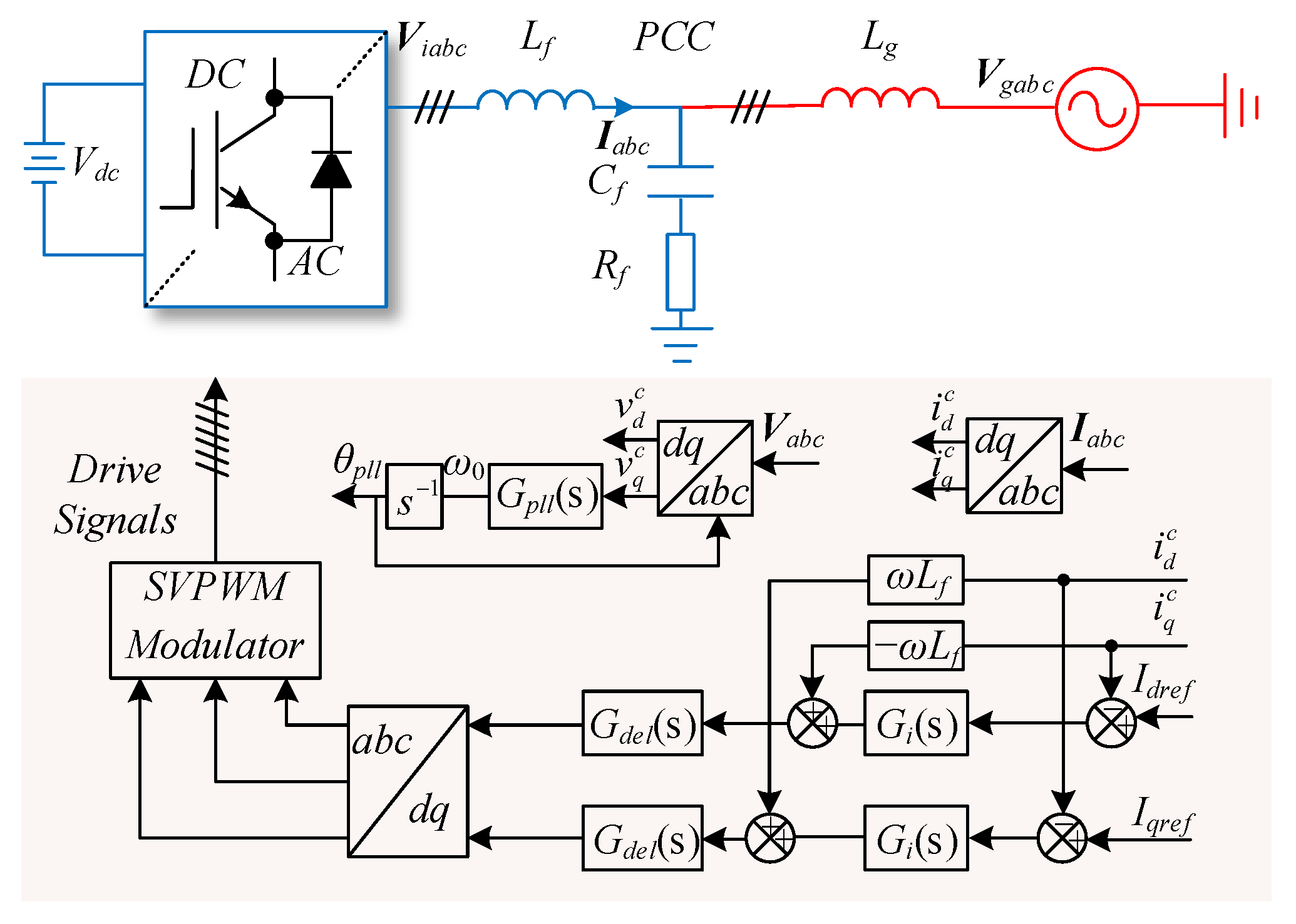
Figure 1. System topology and control diagram.
Energies 17 04450 g001
Figure 2. (a) Control block of GCI with PLL effects. (b) Equivalent diagram.
Energies 17 04450 g002
Figure 3. The GNC plot under weak grid (a) Lg = 16 mH, without PLL effect (b) Lg = 9 mH, with PLL effect (c) Lg = 16 mH, with PLL effect.
Energies 17 04450 g003
Figure 4. Bode plot of GCI impedance in qq-axis.
Energies 17 04450 g004
Figure 5. (a) PLL considering grid impedance (b) current control of GCI with PLL effects considering grid impedance.
Energies 17 04450 g005
Figure 6. The improved PLL.
Energies 17 04450 g006
Figure 7. Dynamic tracking frequency comparison between the improved PLL and the conventional PLL.
Energies 17 04450 g007
Figure 8. The GNC plot with proposed compensation method when Lg = 16 mH.
Energies 17 04450 g008
Figure 9. The Bode plot of GCI output impedance with and without compensation.
Energies 17 04450 g009
Figure 10. The GNC plot under Rv = 2 (a) case I; (b) case II; (c) case III; (d) case IV; (e) case V.
Energies 17 04450 g010
Figure 11. Experimental setup.
Energies 17 04450 g011
Figure 12. Waveforms under (a) Lg = 9 mH and (b) Lg = 16 mH (c) FFT analysis of unstable current.
Energies 17 04450 g012
Figure 13. Waveforms with proposed compensation under (a) Rv = 1, (b) Rv = 2, and (c) Rv = 4.
Energies 17 04450 g013
Figure 14. FFT of current under Figure 13 (a) Rv = 1, (b) Rv = 2, and (c) Rv = 4.
Energies 17 04450 g014
Figure 15. Case I (a) voltage and current waveforms (b) the stable waveforms (c) the unstable waveforms.
Energies 17 04450 g015
Figure 16. DFT of current under case I.
Energies 17 04450 g016
Figure 17. Case II. (a) The stable waveforms; (b) the unstable waveforms.
Energies 17 04450 g017
Figure 18. Case III. (a) The stable waveforms; (b) the unstable waveform.
Energies 17 04450 g018
Figure 19. (a) The stable waveforms of case IV; (b) the stable waveforms of case V.
Energies 17 04450 g019
Figure 20. Rv = 2. (a) The waveforms of frequency changes 0.5 Hz; (b) the stable waveforms of frequency changes −0.5 Hz.
Energies 17 04450 g020
Table 1. System parameters.
ParameterValues
DC-link voltage Vdc400 V
Grid voltage RMS value Vg130 V
Rated power Pn2 kW
Filter inductors Lf3 mH
Filter capacitors Cf20 μF
Damping resistors Rf10 Ω
Grid inductors Lg9/16 mH
Switching frequency fsw10 kHz
Sampling frequency fs10 kHz
Proportional gain of Gi kpi5.24
Integral gain of Gi kii1370
Proportional gain of Gpll kppll4.2
Integral gain of Gpll kipll384
Table 2. Test cases.
CasesLmg (mH)Lg (mH)PLL Parametersdq-Axis Current (A)
I1616kppll = 4.2, kipll = 384Idref = 10, Iqref = 2
II1616kppll = 4.2, kipll = 484Idref = 10, Iqref = 0
III1617.5kppll = 4.2, kipll = 384Idref = 10, Iqref = 0
IV4.8 (−70% Lg)16kppll = 4.2, kipll = 384Idref = 10, Iqref = 0
V41.6 (+160% Lg)16kppll = 4.2, kipll = 384Idref = 10, Iqref = 0
Disclaimer/Publisher’s Note: The statements, opinions and data contained in all publications are solely those of the individual author(s) and contributor(s) and not of MDPI and/or the editor(s). MDPI and/or the editor(s) disclaim responsibility for any injury to people or property resulting from any ideas, methods, instructions or products referred to in the content.