1. Introduction
Renewable resources are becoming increasingly popular due to the increasing demand for electricity consumption. This proliferation also introduces new challenges for a power system. For example, islanding poses one of the significant challenges to the safe operation of a power system [
1]. Islanding is when a load is supplied by a generator disconnected from the main grid [
2]. The combination of the load and the generator is a microgrid. Generally, a microgrid combines generations, lines, and loads working dependently or independently from the main grid.
Islanding can occur either intentionally or unintentionally [
3]. In an intentional islanded operation, the goal is to maintain power flow in a part of the grid isolated from the main grid. Some advantages of intentional islanding include facilitating recovery, increasing system reliability, and preventing economic losses. Maintaining an island by distributed generation necessitates fulfilling specific requirements, such as real and reactive power controls, coordination among distributed generations to compensate for island load fluctuations, voltage control, and synchronization during reconnection. Unintentional islanding occurs when a portion of the grid, due to cyberattacks, faults, protection system errors, or switch failures, separates from the main grid and continues to supply power to the island at a voltage and frequency different from the main grid [
4]. Since maintaining the island is not a consideration of the power system design and operation, unintentional islanding can lead to adverse consequences for both the grid and consumers.
Throughout the islanded operation, fluctuations in distributed energy resources (DER) output parameters can cause detrimental effects on the microgrid and the maintenance personnel, ranging from power quality degradation, negative effects on sensitive and important loads, life-threatening for maintenance personnel or residents, severe or slight changes in frequency and voltage, changes in inverter-based resources (IBR) output current [
5], asynchronous reclosing, malfunction in protection relays, and the possibility of IBR damaging when the grid returns. Therefore, an accurate islanding detection method is important for the safe operation of a power system and microgrid. From the viewpoint of the IEEE standard 1547, the delay of the open–close mechanism should be the only time available for islanding detection.
During islanded operation, a microgrid can operate in one of the following three ways: the first is to turn off the generations of the microgrid, where the IEEE standard 1547 requires islanding detection and turning off the generations in less than two seconds [
6]; the second is the ride-through operation of microgrid generations; the third maintains the islanded microgrid by balancing the generation and the load demand. For each approach, islanding detection is necessary. Islanded operation is indeed detectable using the current measurement of the main circuit breaker. In certain scenarios, when the current passing through the breaker is zero, the detection of islanded operation becomes impossible solely through current measurements. This scenario is when the voltages on two sides of the breaker are the same, and no current passes through the breaker. Most islanding detection methods are proposed to detect islanded operations in such situations. Although it may seem that the most obvious islanding detection method is to monitor the status of switches, the distribution system, unlike the transmission system, does not have a comprehensive data collection system. Such monitoring in the distribution network would require substantial expenditures to establish this system. Therefore, alternative methods are typically employed for islanding detection.
A simple islanding detection method uses conventional frequency and voltage protections [
7]. Installing these protections is usually mandatory and is used to maintain the frequency within 1% and the voltage around 10% of the nominal value. If there is a significant imbalance between the real power generated by the distributed generation and the load, the frequency falls outside the desired range, activating the frequency protection. A similar situation may occur for voltage due to reactive power imbalance, causing the voltage protection to activate and disconnect the generation from the grid, thus eliminating the island. While these two protections provide a simple method for detecting and mitigating an islanded operation, problems arise when the imbalances are not large enough to trigger the protections. The island can operate at different but acceptable voltage and frequency levels in such cases. Therefore, other proposed methods have a smaller NDZ and better operational speed.
Islanding detection methods are primarily divided into two categories: remote and local [
8]. Remote islanding detection methods are mainly based on communication infrastructures. An example is the power line carrier method. This method sends an islanding signal to the control center once the main circuit breaker is disconnected. Local islanding detection methods are generally categorized into active and passive approaches. Passive islanding detection methods use the point of common coupling (PCC) measurements to detect islanded operation [
9]. These methods often have a significant nondetection zone (NDZ) but are easy to implement [
10]. Reference [
11] proposed an advanced passive islanding detection method for systems incorporating multiple inverters. Reference [
12] introduced an index for postprocessing by estimating the number of peaks and valleys within a cycle using a sliding window, enabling the detection of islanded operation based on the statistical features of the square of the RMS value and the average crest factor. Reference [
13] detected islanding based on the cumulative sum of superimposed impedances. Reference [
14] introduced a method for islanding detection based on the long short-term memory network. Reference [
15] proposed a passive islanding detection method based on the frequency deviations using chaos theory. This study applies a forced Helmholtz oscillator to detect islanded operations for multiple distributed generations.
Active islanding detection methods inject perturbation into the inverter output parameters and detect the islanded operation based on the changes in measurement. The perturbation facilitates islanding detection and decreases the NDZ but causes power quality degradation. Reference [
16] employed a small magnitude current injection via
-axis current controller. Reference [
17] presented an islanding detection method using a modified active frequency drift. This method proposes a reduced total harmonic distortion without affecting the reliability of the active frequency drift method. Reference [
18] incorporated a frequency locked-loop (PLL) that utilizes the voltage phase and frequency at the point of common coupling (PCC), along with a modified auto phase shift (APS), to enable decentralized power generation systems for effective islanding detection. Reference [
19] presented a method for islanding detection that leverages the rate of change of kinetic energy and the RMS value of absolute frequency deviation, specifically designed to operate effectively under perfectly matched loading conditions. Hybrid methods combine passive and active islanding detection methods to use their advantages and reduce drawbacks.
The noise effect is neglected in most of the mentioned passive and active islanding detection methods. High ambient noise levels applied to the PCC point measurements can disturb most islanding detection methods. The noise can arise from switching transients, harmonics, grounding issues, voltage sag and swell, electromagnetic interference (EMI), external sources of electromagnetic fields, and power quality issues. For example, a radio frequency (RF) signal, lightning, and the corona effect of a high voltage transmission line can interfere with islanding detection. However, it is important to detect islanded operations in a noisy environment with a small NDZ. The main contribution of this paper is reducing the noise effects on islanding detection. The proposed method utilizes a signal processing approach using a classical Duffing equation to mitigate the impact of noise on islanding detection. The main point of using the Duffing oscillator for islanding detection is that even under a high noise, the Duffing oscillator can discern small periodic signals by altering its phase trajectory from periodic to chaotic mode. The method is tested under different load quality factors and switching events probable for a power system. The proposed method has a negligible NDZ in a high-noise environment, a small detection period, and easy and low-cost implementation. The proposed method is validated in a 3.6 kW PV setup.
Section 2 of this paper presents the study system.
Section 3 discusses the application of the Duffing oscillator in weak signal detection and its characteristics on islanding detection, as well as analyzing the proposed method and the noise effect on the islanding detection.
Section 4 discusses the simulation and implementation results in grid-connected and islanded operations. Finally,
Section 5 concludes the paper.
2. Study System
Figure 1 shows the study system contains a primary source with a voltage-sourced converter (VSC), main grid, and load [
7]. The system can work either in grid-connected or islanded modes when the circuit breaker is closed or open, respectively. The primary source and the VSC are connected to the PCC point through a transformer and a series filter which are represented by
and
in
Figure 1. The Thevenin equivalent of the main grid is modeled by a voltage source, the equivalent impedance
of the power system, and the equivalent inductance
of the lines and loads [
20]. The study system parameters are mentioned in
Table 1.
According to (
1), once the load reactive power supplied from the main grid
decreases, the primary source should supply the reactive power shortage of the load
[
5]. However, for the islanded operation,
is eliminated from (
1), and the primary source should supply the reactive power of the load solely. Thus, a proper islanding system is necessary to control the PCC voltage before and after the islanded operation and to compensate for the load reactive power.
During a grid-connected operation, an islanding system regulates the output current of the inverter. When the grid is disconnected, the voltage may exceed its threshold [
21]. Once the main circuit breaker is disconnected, the PCC voltage must meet the standard criteria. The islanding detection system is responsible for detecting the islanded operation and must modify the grid-following to the grid-forming inverter mode. In the grid-forming inverter mode, the inverter injects the needed reactive power and maintains the PCC voltage in the normal range.
3. Application of the Duffing Oscillator for Weak Signal Detection
The Duffing equation is generally based on the Rayleigh differential Equation (
2):
considering
as the derivative of x with respect to time,
is a nonlinear expression. If
is chosen as
, (
2) changes to:
Equation (
3) is the van der Pol–Duffing equation. By choosing
and
the classical Duffing equation is obtained as:
Equation (
4) is a nonperturbed Duffing equation. By adding
to the right side of (
4), the perturbed Duffing equation is as follows [
22]:
which is the general form of a classical Duffing equation. In (
5),
controls the system damping by dissipating energy and decreasing the amplitude of oscillations over time. The linear stiffness of the system is controlled with
. It measures how the system responds to small displacements from equilibrium. The restoring force nonlinearity is controlled by
,
is the driving force amplitude, and
is the angular frequency of the driving force.
The sensitivity of the Duffing oscillator on its initial conditions is used to develop an islanding detection system [
23]. The finite cycles in nonlinear systems enable the analysis of state variables through the bifurcation feature [
24]. By increasing
in (
5), the period (
) of state variables for the Duffing system doubles. For example, it increases from
to
or from
to
. This change in the state of the oscillator is bifurcation. Bifurcation in the Duffing oscillator happens several times, for
,
,
, and
, and the other bifurcation happens when
. Increasing
causes the state variables of the Duffing oscillator to be in order mode in the time domain. This is the order state of the Duffing oscillator. Increasing
changes the Duffing state to chaotic mode. In two- or more-dimensional state spaces, an oscillating response is also one of the possible system responses. The movement of state variables along a closed loop indicates periodic oscillations within the system. When the state trajectory approaches this loop, the system is regarded as stable; otherwise, it is unstable [
24]. This paper shows that an islanding event is detectable using the phase plane trajectory of the Duffing oscillator and by changing the state from order to chaos under a high-noise environment.
Equation (
5) presents a nonlinear elastic system with the damping ratio
, nonlinear restoring force
, and the driving force
. The nonlinear dynamic system has four modes, and two of the four modes, the order and chaos modes, are used to detect the islanded operation [
25]. To investigate the changes on
, this paper considers
and
to solve the second-order differential equation using the Runge–Kutta algorithm with a step size of
, which fixes
. Equation (
6) is obtained by substituting the constants in (
5) considering the PCC voltage and the added noise as the perturbations:
where
is the critical point of the Duffing oscillator, and the changes in
can change the state of the system based on the bifurcation. The frequency of the driving force in (
5) under a high-noise environment is equal to the frequency of the signal to be detected. This is characteristic of the Duffing oscillator when the frequency of the driving force is the same as the signal to be detected the Duffing oscillator adds the amplitudes of the driving force to the signal [
26]. When the Duffing oscillator is in a critical state, minor changes in system measurements can lead to significant state changes. Increasing
to values more than
changes the state of the Duffing oscillator from order to chaos. Transitioning from an order to a chaotic state in a high-noise environment changes the coefficients of the fast Fourier transform (FFT) of the Duffing equation output
y. FFT coefficients change from symmetrical to unsymmetrical waveforms when
surpasses
. The even coefficients of the FFT(
y) for symmetrical waveforms are almost zero. However, for the unsymmetrical waveforms, the even and odd coefficients of FFT(
y) have values other than zeros [
27]. Using FFT(
y) for islanding detection, the third and fourth harmonics differences are used as the criteria to send the islanded operation signal to the inverter.
The main difficulty of passive islanding detection methods is determining the threshold. Determining the threshold is important since the detection accuracy depends on the threshold. This paper uses the Melnikov function [
23] to calculate the threshold of
as the amplitude of the driving force [
28] for the Duffing oscillator in islanding detection. This function is a predictive tool for nonlinear dynamical systems subjected to periodic perturbations [
29]. By analyzing the Melnikov function and identifying when it equals zero, the potential for chaotic dynamics of the Duffing oscillator is revealed subjected to periodic perturbations [
30].
To find the threshold, the chaotic state needs to be considered, when
and
, then the threshold for
in (
8) is obtained using residue theorem and direct integration [
24]:
Equation (
8) is valid for
and
. Using this criterion, the amplitudes of the driving force and the signal to be detected add to each other once the driving force and the input signal have small enough frequency differences. The Duffing oscillator can detect a small signal buried in the noise environment if and only if the difference between the frequency of the driving force and the signal to be detected is almost the same (
).
4. Applying Duffing Oscillator to Islanding Detection
Islanding detection using a Duffing oscillator is based on monitoring voltage fluctuations of the PCC. Disconnection of the inverter is necessary for the grid-following inverters when the voltage is outside the normal operating range. Once the main circuit breaker is disconnected, the islanding system should change the operation strategy from grid-connected to islanded mode. Using a grid-forming inverter, the inverter continues to operate in island mode when the main circuit breaker is disconnected from the main grid and during islanded operation. The grid-forming inverter maintains the voltage and frequency of the island and stabilizes the island for resynchronization [
21]. Considering a PV system as the primary source, the injected power from the PV system is
, and the difference in power supplied from the main grid is
.
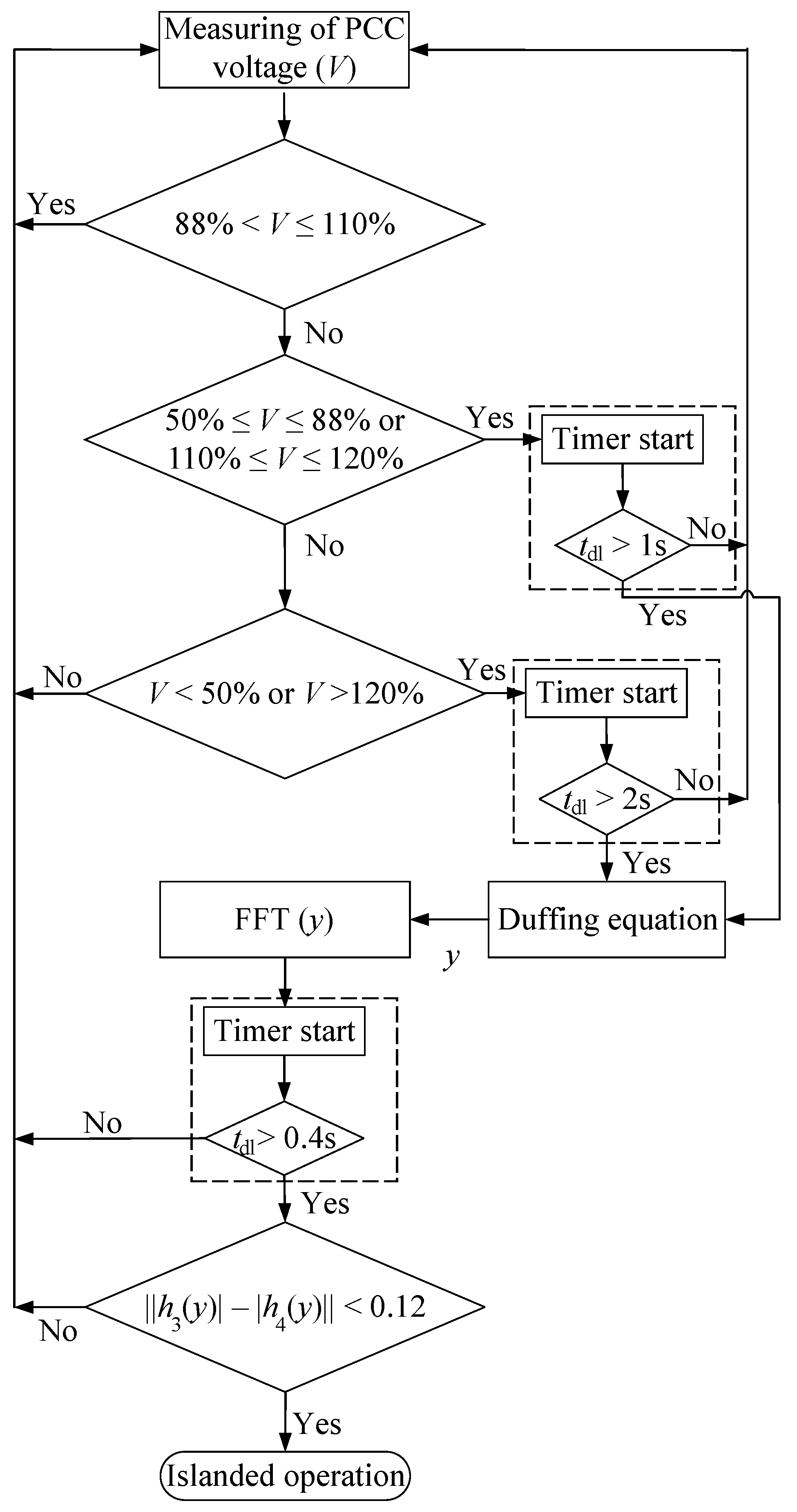
The protection mechanism detects an islanded operation through voltage deviations beyond the standard range. Following the IEEE standard 1547, the voltage range in a grid-connected operation is between 88% and 110% of the nominal voltage.
Table 2 represents the response of DER to abnormal voltage conditions of a power system [
6]. This table guides the appropriate setting of DER trip functions in response to abnormal voltage conditions, promoting the reliability and security of the grid [
6]. In this table, OV reflects the overvoltage and UV reflects the undervoltage limits.
Three different conditions are probable for islanding detection using the Duffing oscillator. The first condition is when the output reactive power of the PV is equivalent to the power demand of the load. In this condition, the Duffing oscillator is accompanied by the rate of change of voltage (ROCOV) for islanding detection. Differentiating the voltage variations using ROCOV magnifies the smallest changes and facilitates the islanding detection [
31]. In the second condition, the reactive power is injected from the grid into the local load
, whereby the PCC voltage is lower than the grid voltage during the islanded operation. In the third scenario, reactive power is injected from the local load into the grid
, where the PCC voltage is greater than the grid voltage during islanded operation.
4.1. Analysis of the Proposed Method
In (
5), the driving force frequency is
rad/s. The normal frequency of the grid is 60 Hz. The grid dynamics, including load and generation changes, change the normal operation frequency based on
Table 3 [
6]. The Duffing equation frequency for islanding detection should be compatible with the normal frequency range of the main grid. This normal frequency is not necessarily limited to 60 Hz. To match the grid frequency with the Duffing oscillator driving force frequency, an array of Duffing oscillators is used in this paper to cover the whole normal frequency domain of a 60 Hz power system.
Based on
Table 3, to ensure the synchronous operation of the detection system with the grid frequency, it is imperative to set a specific driving force frequency range for the Duffing array between 58.5 Hz and 61.2 Hz. A frequency transformation of the Duffing equation driving force is indispensable to achieve this requisite frequency alignment. This transformation is realized by substituting a time variable,
t, related to
via the equation
and considering
:
by substituting (
9) in (
6), (
10) is obtained as:
Equation (
10) is used to synchronize the islanding detection method with a power system that works in
f normal operation frequency [
28].
4.2. Noise Effect on the Proposed Islanding Detection Method
In this paper, the noise is considered as an additional input. The dynamics of the system are described in terms of the state variables
x and
y, and the input is added to the system in (
11):
where
is the Gaussian white noise with the root mean square
,
is the small enough frequency difference between the driving force and the voltage signal, where
, and
is the primary phase difference between the driving force and voltage signal. The above transformation led to the construction of the Duffing oscillator array to detect islanded operations in the normal frequency range. This array comprises several uncoupled Duffing oscillators with different frequency definitions. In this array, each Duffing oscillator is responsible for islanding detecting in a very narrow frequency extent
[
32]. The Runge–Kutta algorithm is sensitive to the different step sizes, and there is a truncation (discretization) error when using the Runge–Kutta algorithm due to the infinite Taylor series. The truncation error causes a distinct discrepancy of the critical value
for different step sizes. Changing the step size in numerical simulations does not result in a phase trajectory transition. The only parameter that changes the phase trajectory is
. For the Duffing oscillator, the phase transition happens if and only if the frequency of the voltage signal and the driving force are close enough (
). The total periodic force of the Duffing oscillator containing the driving force, the PCC voltage, and the ambient noise is obtained using (
6) as:
Assuming the total amplitude in (
12) is equal to the
, then
and
are achievable using (
13) and (
14), respectively, [
32] as follows:
and
In (
13) and (
14), there are three probabilities for the Duffing oscillator state. If
is negligible, then
and the phase difference (
) can change the state of the Duffing oscillator. For
, when
the Duffing oscillator remains in its initial state (order mode) [
33]. When
is not in this range, the Duffing oscillator cannot detect the islanded operation correctly. In this paper, the driving force amplitude is considered to be half of the voltage amplitude in normal operation. This consideration causes a negligible NDZ resulting from
. For a significant
, when
, the Duffing oscillator is in its chaotic mode, and for
, it is in its order mode. A feedback loop assesses the number of chaotic Duffing oscillators in the array. The frequency of the Duffing oscillator is calculated using
and checked with the grid frequency. For a significant
, the
effect is negligible on islanding detection.
4.3. Noise Immunity of the Islanding Detection Method
In this study, the power of the noise is increased gradually to check when the proposed method cannot detect the islanded operation through the noise. This point is considered the worst-case signal-to-noise ratio for the proposed method. The noise in this study is the measuring point noise. The power system is considered to work in a remote place such that the noise cannot affect the power system stability. The SNR value represents that for 1 pu of the voltage, the maximum noise amplitude in measurement should not exceed eight times bigger than the voltage signal. However, the proposed method can detect islanded operation in a real power system when the signal-to-noise ratio in PCC is not exceeded by:
The simulation and experimental results show that the proposed islanding detection method detects an islanded operation in an environment with about 7.04 dB signal-to-noise ratio in reality. The noise amplitude is almost three times smaller than a power system voltage signal amplitude in this ratio.
6. Performance Evaluation of the Proposed Islanding Detection Method
Islanding detection methods are evaluated and compared according to several key criteria. These include compatibility with the type of primary energy source, implementation costs, suitability for systems with multiple distributed generators (DG), impact on power quality, the nondetection zone, type of load, quality factor, response time, and vulnerability to cyberattacks.
The proposed islanding detection method is applicable to both inverter-based resources and synchronous generators. However, it is not suitable for systems with multiple DG. A significant advantage of this method is that it does not introduce any disturbances to the power quality of the system and has very low implementation costs. While it is suitable for various load types, capacitive loads affect its performance. According to the UL1741 test [
34], the most challenging scenario for detecting islanded operations occurs when
. The proposed method is capable of detecting islanded operations in this condition and generates an islanding signal. However, it is vulnerable to cyberattacks, and incorporating encryption and decryption mechanisms could improve its resilience against such threats.
6.1. Response Time of the Proposed Islanding Detection Method
Given the detrimental effects of islanded operations on a microgrid, reducing the detection response time is of critical importance. This section compares the response time of the proposed islanding detection method with passive islanding detection methods in
Table 4 [
35].
6.2. Nondetection Zone of the Islanding Detection Method
NDZ presents a range of conditions or situations where an islanding detection method cannot recognize the islanded operation [
36]. Decreasing NDZ is important to ensure the reliability of the islanding detection method. This paper uses the real and reactive power mismatches to calculate NDZ [
37]. For an RLC load, the reactive power of the load is calculated as follows [
31]:
For the grid-connected operation mode of the inverter and considering a unity power factor, the load reactive power equals the reactive power mismatch [
31]:
Considering
, the reactive power mismatch is obtained as follows:
where
is the load nominal frequency,
L is the load inductance,
R is the load resistance,
V is the voltage, and
is the frequency range based on the IEEE standard 1547. Real power mismatch is similarly calculated as [
38]:
Figure 11 shows that the NDZ of the proposed method is smaller than the other references, which can acknowledge the reliability of the islanding detection method. Simulations show that when
is varied between 0.1 and 0.5 pu, a stiff grid (SCR > 5), the proposed method remains robust. The method tolerates variations of up to ±10% in
and
without significant performance degradation. This demonstrates the resilience of the proposed method under real-world conditions. Under weak grid conditions, however, the system becomes unstable.


