

Jet Fuel Contamination: Forms, Impact, Control, and Prevention


Abstract
1. Introduction
2. Conventional and Modern Pathways for Jet Fuel Production
- Two-way catalyst, responsible for dehydrogenation molecules to achieve alkenes and also for hydrogenating olefinic complexes.
- Single-way catalyst, responsible for carbon–carbon bond cutting and hydrogenation of molecules.
- Monofunctional acidic catalysts for molecular hydrogen initiated on Brønsted acid sites, known as “catalytic cracking”.
- A lack of a catalyst for hydropyrolysis in a temperature range from 500 °C up to 600 °C with gaining pressures.
- Annex A1: Fischer–Tropsch hydroprocess synthesized paraffinic kerosene (SPK)—maximum volume in conventional Jet A1 is 50%.
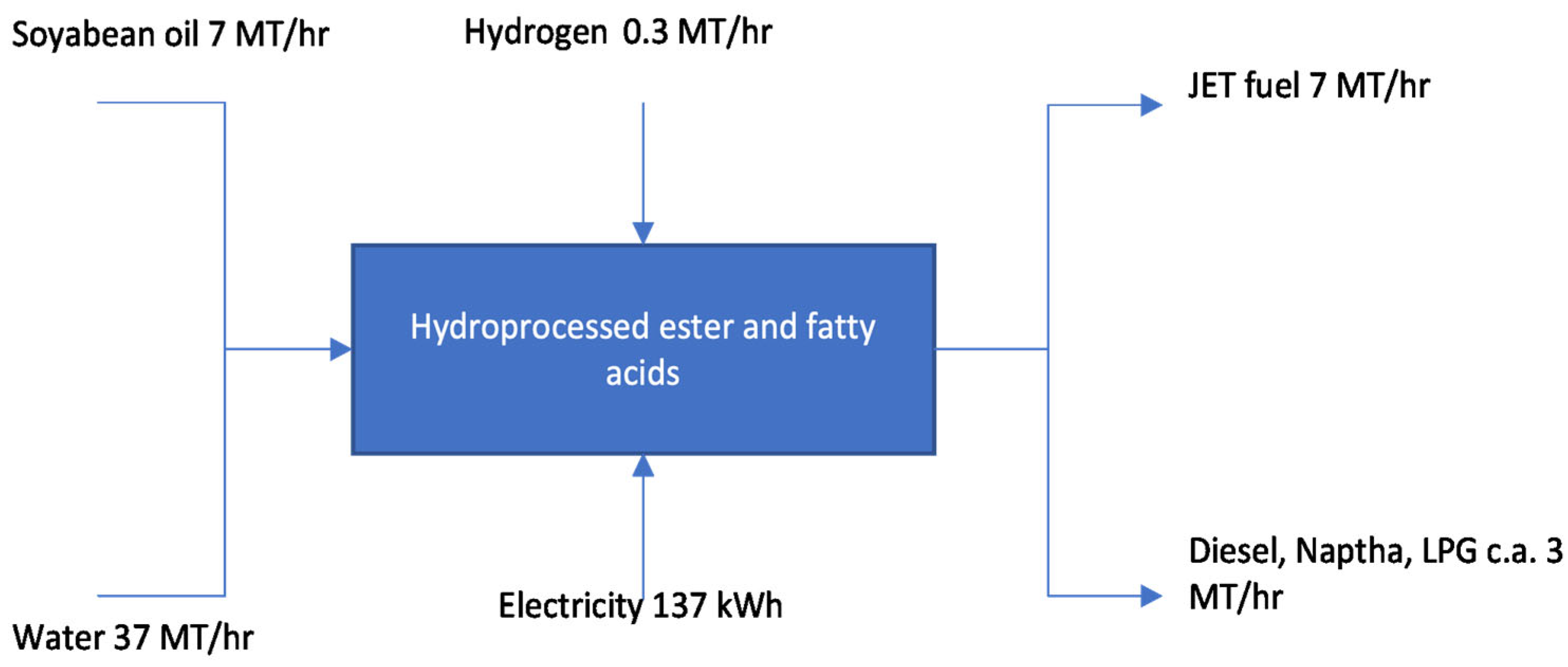
- Annex A2: Synthesized paraffinic kerosene produced from hydroprocessed esters and fatty acids—maximum volume in conventional Jet A1 is 50%.
- Annex A3: Synthesized iso-paraffins (SIP) produced from hydroprocessed fermented sugars—maximum volume in conventional Jet A1 is 50%.
- Annex A4: Fischer–Tropsch Synthesized Paraffinic Kerosene plus Aromatics (SPK/A)—maximum volume in conventional Jet A1 is 50%.
- Annex A5: Alcohol-to-jet synthetic paraffinic kerosene (ATJ-SPK)—maximum volume in conventional Jet A1 is 50%.
- Annex A6: Catalytic hydrothermolysis jet (CHJ)—maximum volume in conventional Jet A1 is 50%.
- Annex A7: Synthesized paraffinic kerosene from hydroprocessed hydrocarbons, esters, and fatty acids (HC-HEFA SPK)—maximum volume in conventional Jet A1 is 10%.
3. Characterization of the Main Types of Contamination in Aviation Fuels
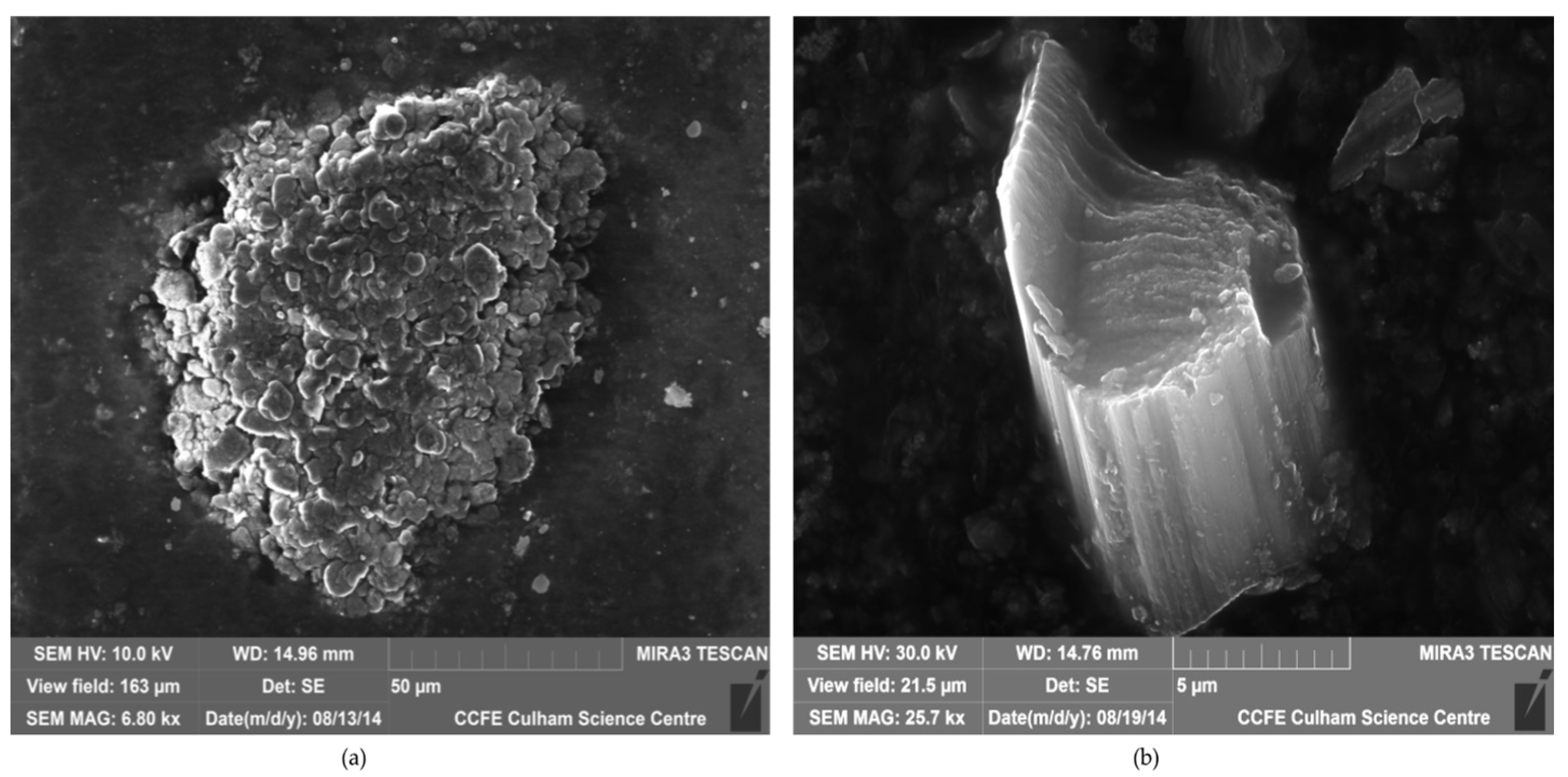
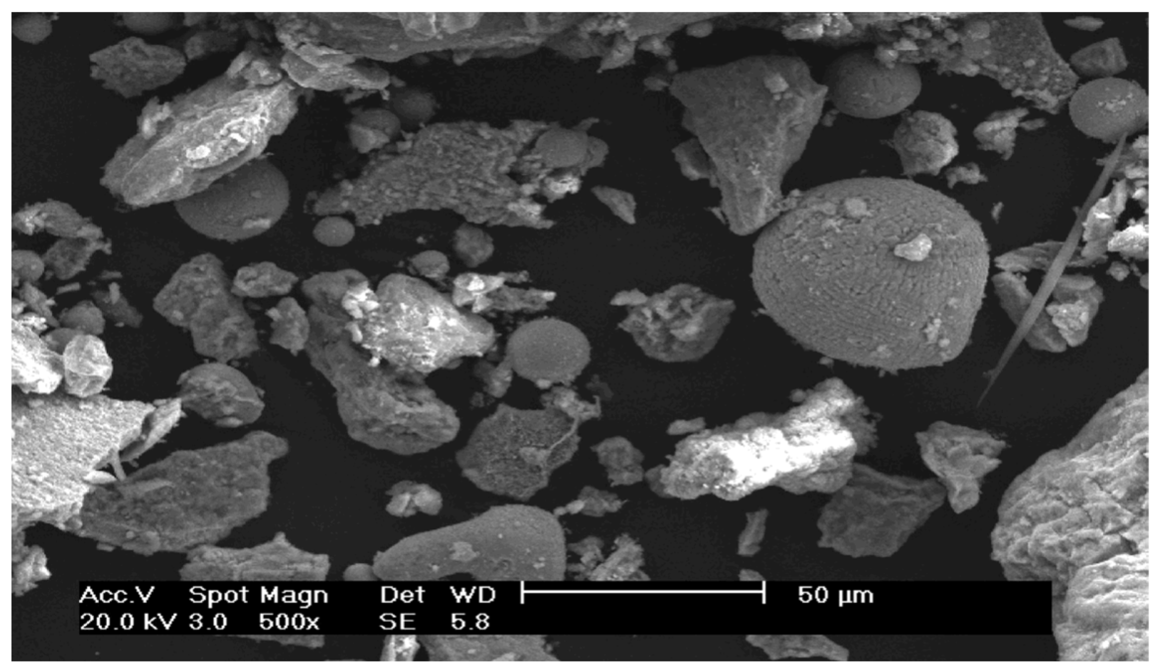
3.1. Solid Particulates and Trace Element Contamination
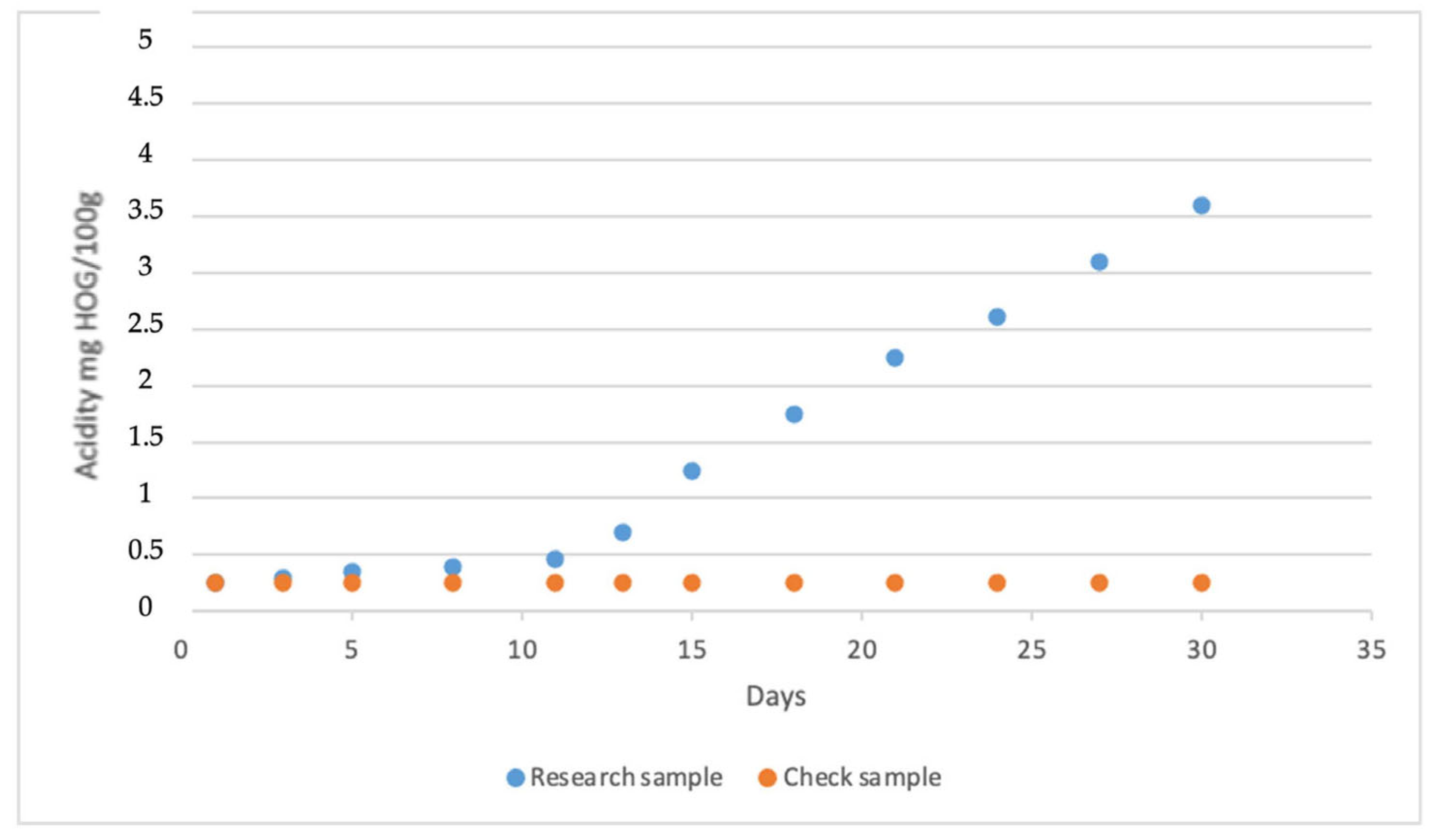
3.2. Microbiological Contamination
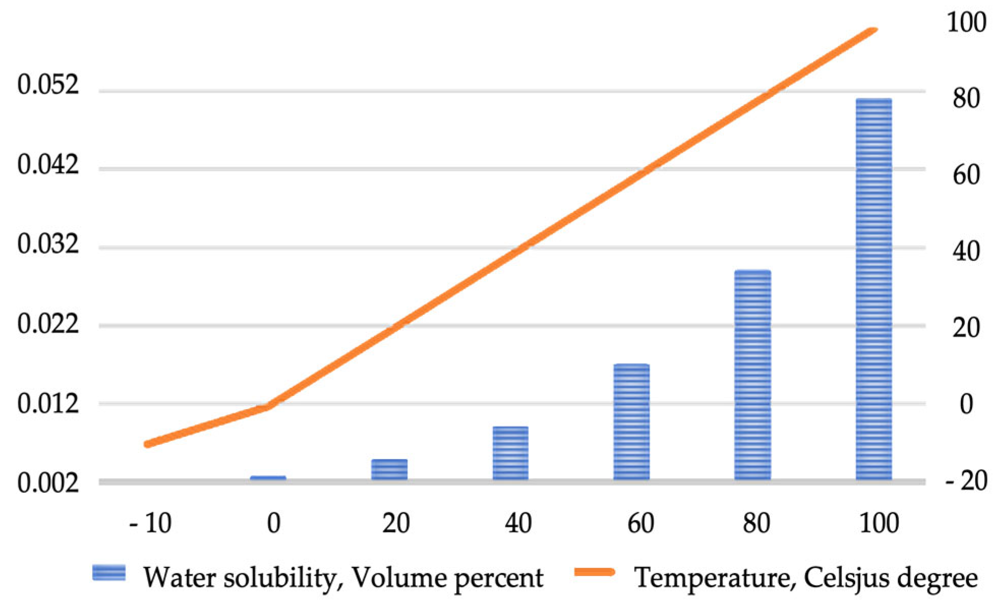
3.3. Water Contamination
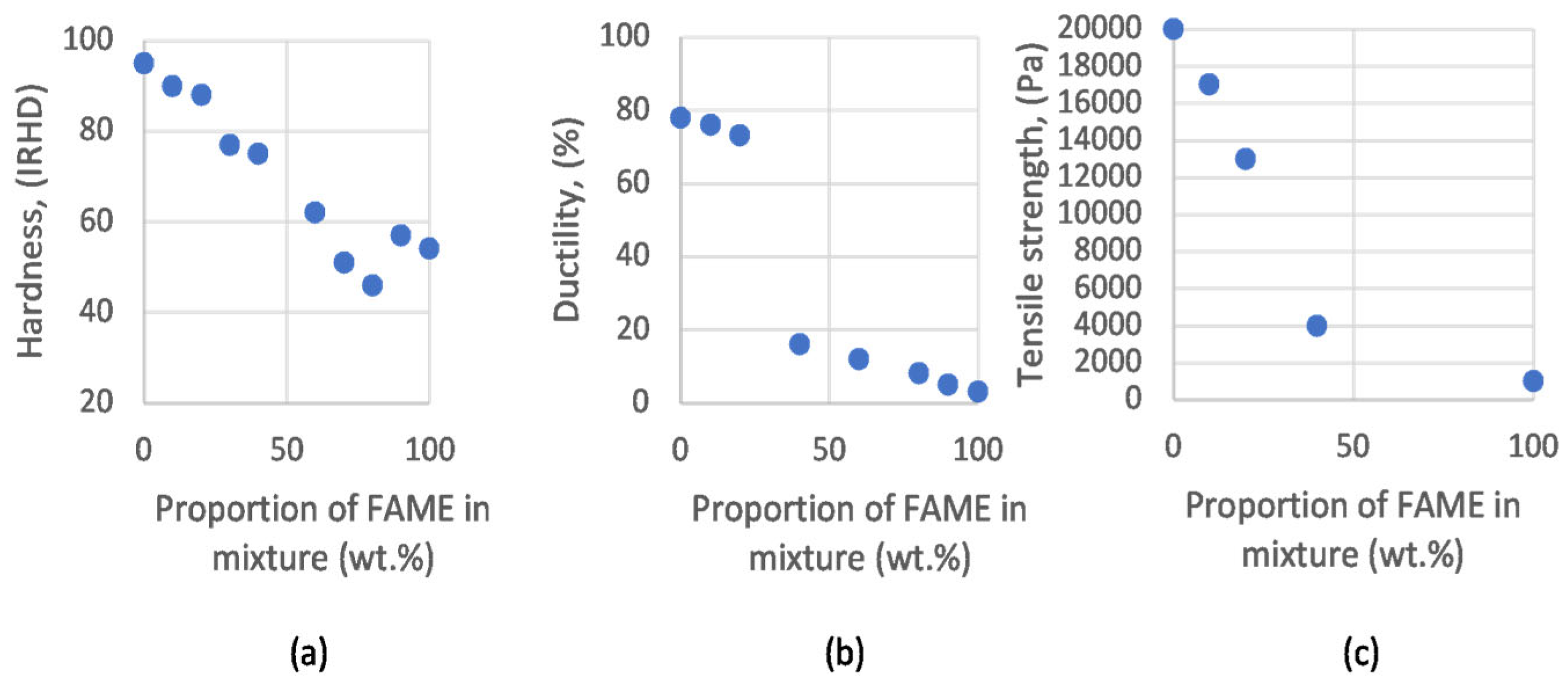
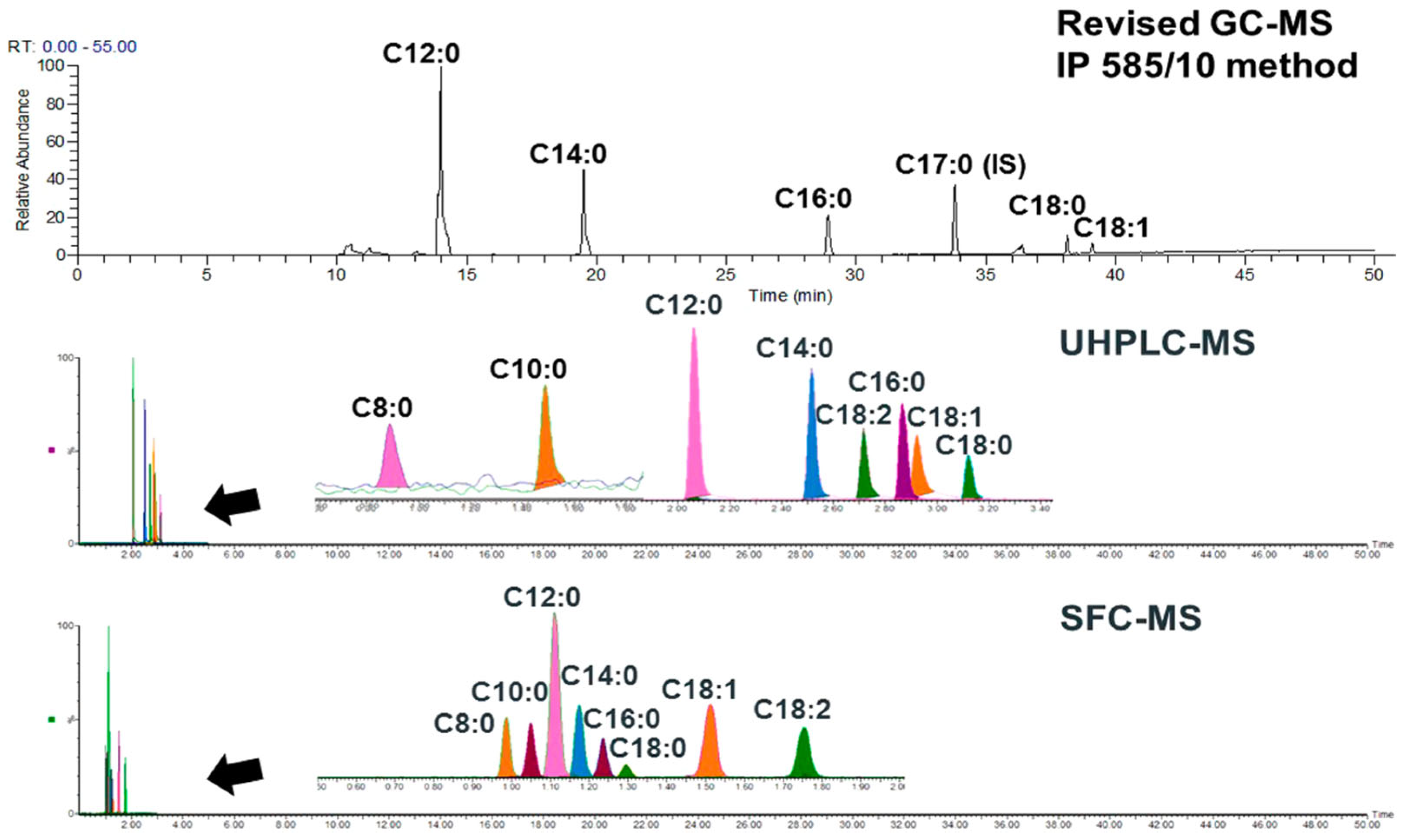
3.4. Jet Fuel Contamination from Other Fuels and FAME Contamination
4. Conclusions
Author Contributions
Funding
Data Availability Statement
Acknowledgments
Conflicts of Interest
Abbreviations
| ATP | Adenosine Tri-Phosphate |
| AF | Advanced Fermentation |
| ATJ | Alcohol To Jet |
| ATJ-SPK | Alcohol To Jet Synthetic Paraffinic Kerosene |
| AJF | Alternative Jet Fuels |
| ASTM | American Society for Testing and Materials |
| AOX | Antioxidants |
| APP | Aqueous Phase Processing |
| AAS | Atomic Absorption Spectrometry |
| AFQRJOS | Aviation Fuel Quality Requirements for Jointly Operated Systems |
| BSE | BackScattered Electrons |
| CHJ | Catalytic Hydrothermolysis Jet |
| CoQ | Certificate of Quality |
| CFU | Colony Forming Units |
| DGGE | Denaturing Gradient Gel Electrophoresis |
| ETR | Elliptometric Tube Rating |
| ETS | Emissions Trading System |
| EDX | Energy-Dispersive X-ray |
| FPH | Fast Pyrolysis and Hydroprocessing |
| FAME | Fatty Acid Methyl Ester |
| FM | Filter Monitor |
| FWS | Filter Water Separator |
| SPK/A | Fischer-Tropsch Synthesized Paraffinic Kerosene plus Aromatics |
| FT-SPK | Fischer-Tropsch Synthetic Paraffinic Kerosene |
| FAAS | Flame Atomic Absorption Spectrometry |
| FQIS | Fuel Quantity Indication System |
| FRTHC | Full Recycled Tail oil to HydroCracking reactor |
| FRTHT | Full Recycled Tail oil to HydroTreating reactor |
| GC-MS | Gas Chromatography—Mass Spectrometry |
| GFAAS | Graphite Furnace Atomic Absorption Spectrometry |
| HTS | High-Throughput Sequencing |
| HEFA | Hydroprocessed Esters and Fatty Acids |
| HTL | HydroThermal Liquefaction |
| ICP-MS | Inductively Coupled Plasma—Mass Spectrometry |
| ICP-OES | Inductively Coupled Plasma Optical Emission Spectrometry |
| ITR | Interferometric Tube Rating |
| ITS | Internal Transcribed Spacers |
| ICAO | International Civil Aviation Organization |
| JIG | Joint Inspection Group |
| LOD | Limit Of Detection |
| LOQ | Limit Of Quantification |
| MALDI-TOF MS | Matrix-Assisted Laser Desorption/Ionization Time-Of-Flight Mass Spectrometry |
| MIC | Microbiologically Influenced Corrosion |
| NAA | Neutron Activation Analysis |
| NMCC | Nishina Memorial Cyclotron Center |
| PRTHT | Partial tail oil Recycled To HydroTreating reactor |
| PFC | Perfluorinated Chemicals |
| POFBG | PMMA based Optical Fiber Bragg Grating |
| PMMA | PolyMethyl MethAcrylate |
| POF | Polymer Optical Fibre |
| PCR | Polymerase Chain Reaction |
| PMA | Propidium MonoAzide |
| qPCR | quantitative Polymerase Chain Reaction |
| RLU | Relative Light Units |
| RED III | Renewable Energy Directive |
| RED-T | Renewable Energy Directive used in Transport |
| RFNBO | Renewable Fuels of Non-Biological Origin |
| SEM | Scanning Electron Microscopy |
| SSOTP | Single Stage Once Through Process |
| SPE-FTIR | Solid Polymer Electrolyte Fourier Transform Infra-Red |
| SDA | Static Dissipator Additive |
| SRB | Sulphate Reducing Bacteria |
| SAF | Sustainable Aviation Fuel |
| SIP | Synthesized Iso-Paraffins |
| HC-HEFA SPK | Synthesized paraffinic kerosene from hydroprocessed hydrocarbons, esters and fatty acids |
| SBC | Synthetic Blend Component |
| TEM | Transmission Electron Microscopy |
| QQQ-ICP-MS | Triple Quadrupole ICP-MS |
| TSA | Tryptone Soya Agar |
| GC × GC | Two-dimensional gas chromatography |
| UHC | Unburned HydroCarbons |
| UHPSFC-MS | UltraHigh-Performance Supercritical Fluid Chromatography—Mass Spectrometry |
| UHC | Unburned HydroCarbons |
| UCO | Used Cooking Oil |
| VGO | Vacuum Gas Oil |
| ViPA | Visual Process Analyzer |
| XRD | X-ray diffraction |
References
- Yang, W.; Gao, Y.; Casey, J.F. Determination of Trace Elements in Crude Oils and Fuel Oils: A Comprehensive Review and New Data. In Solution Chemistry: Advances in Research and Applications; Nova Science Publishers: Hauppauge, NY, USA, 2018. [Google Scholar]
- IATA. Commitment to Fly Net Zero; International Civil Aviation Organization: Montreal, QC, USA, 2022. [Google Scholar]
- Cabrera, E.; de Sousa, J.M.M. Use of Sustainable Fuels in Aviation—A Review. Energies 2022, 15, 2440. [Google Scholar] [CrossRef]
- Marszałek, N.; Lis, T. The future of sustainable aviation fuels. Combust. Engines 2022, 191, 29–40. [Google Scholar] [CrossRef]
- International Civil Aviation Organization. Sustainable Aviation Fuels Guide; International Civil Aviation Organization: Montreal, QC, Canada, 2017. [Google Scholar]
- Bauen, A.; Bitossi, N.; German, L.; Harris, A.; Leow, K. Sustainable Aviation Fuels. Johns. Matthey Technol. Rev. 2020, 64, 263–278. [Google Scholar] [CrossRef]
- Rumizen, M.A. Qualification of Alternative Jet Fuels. Front. Energy Res. 2021, 9, 760713. [Google Scholar] [CrossRef]
- International Air Transport Association. Fact Sheet 2: Sustainable Aviation Fuel: Technical Certification; International Air Transport Association: Montreal, QC, Canada, 2020. [Google Scholar]
- DEF STAN 91-091; Turbine Fuel, Kerosene Type, Jet A-1; NATO Code: F-35 Joint Service Designation: AVTUR. Ministry of Defence: Oakland, CA, USA, 2023.
- Colket, M.; Heyne, J.; Rumizen, M.; Gupta, M.; Edwards, T.; Roquemore, W.M.; Sankaran, V. Overview of the national jet fuels combustion program. AIAA J. 2017, 55, 1087–1104. [Google Scholar] [CrossRef]
- EI/JIG Standard EI 1533; Quality Assurance Requirements for Semi-Synthetic Jet Fuel and Synthetic Blending Components (SBC). Energy Institute: London, UK, 2022.
- EI/JIG Standard 1530; Standard to Assist All Parties in the Maintenance of Aviation Fuel Quality, from Its Point of Manufacture through to Delivery to Airports. Energy Institute: London, UK, 2019.
- Brailko, A.A.; Samoylenko, V.M.; Druzhinin, N.A.; Druzhinin, L.A. Adaptive information management system of dynamic monitoring of actual water content in jet fuel in technological processes of aviation fuel supply. Civ. Aviat. High Technol. 2022, 25, 20–29. [Google Scholar] [CrossRef]
- Vidyasagar, K. Quality control of aviation turbine fuel on aircraft and ground, its methods, requirements, and consequences: A safety and hazard analysis. Int. J. Petrochem. Eng. Technol. IJPET 2023, 2, 15–46. [Google Scholar]
- Baena, S.; Repetto, S.L.; Lawson, C.P.; Lam, W. Behaviour of Water in Jet Fuel A Literature Review. Prog. Aerosp. Sci. 2013, 60, 35–44. [Google Scholar] [CrossRef]
- Dodos, G.S.; Zannikos, F. Microbiological Growth Study of Biodiesel Fuel. SAE Int. J. Fuels Lubr. 2013, 6, 419–429. [Google Scholar] [CrossRef]
- Mccomb, J.P. A Metagenomic Analysis of Microbial Contamination in Aviation Fuels. Master’s Thesis, University of Dayton Research Institute, Dayton, OH, USA, 2009. [Google Scholar]
- Shkilniuk, I.; Shevchuk, N. Monitoring the Risks of Microbiological Contamination of Aviation Fuels and Fuel Systems. In Modern Technologies in Energy and Transport; Springer: Cham, Switzerland, 2024; pp. 235–248. [Google Scholar]
- Angolini, C.F.F.; Pilau, E.J.; Lopes-Oliveira, P.F.; Garcia, I.N.S.; Gozzo, F.C.; de Oliveira, V.M.; Marsaioli, A.J. Classification and Identification of Petroleum Microorganisms by MALDI-TOF Mass Spectrometry. J. Braz. Chem. Soc. 2015, 26, 513–520. [Google Scholar] [CrossRef]
- Uryga-Bugajska, I.; Pourkashanian, M.; Borman, D.; Catalanotti, E.; Wilson, C.W. Theoretical investigation of the performance of alternative aviation fuels in an aero-engine combustion chamber. Proc. Inst. Mech. Eng. Part G J. Aerosp. Eng. 2011, 225, 874–885. [Google Scholar] [CrossRef]
- Lapuerta, M.; Canoira, L. The Suitability of Fatty Acid Methyl Esters (FAME) as Blending Agents in Jet A-1. In Biofuels for Aviation; Elsevier: Amsterdam, The Netherlands, 2016; pp. 47–84. [Google Scholar]
- Joint Inspection Group. Guidance on Managing FAME in Jet Fuel (BULLETIN 106); Joint Inspection Group: Cambridge, UK, 2018. [Google Scholar]
- ASTM D7566-22; Standard Specification for Aviation Turbine Fuel Containing Synthesized Hydrocarbons. ASTM International: West Conshohocken, PA, USA, 2022.
- Kousoulidou, M.; Lonza, L. Biofuels in aviation: Fuel demand and CO2 emissions evolution in Europe toward 2030. Transp. Res. D Transp. Environ. 2016, 46, 166–181. [Google Scholar] [CrossRef]
- Shabalin, Y.A.; Sarilov, M.Y.; Shakirova, O.G. Demercaptanization of Straight-Run Kerosene Fraction According to ‘Demerus Jet’ Technology; Springer Science and Business Media Deutschland GmbH: Berlin/Heidelberg, Germany, 2021; pp. 310–318. [Google Scholar]
- Motahari, K.; Abdollahi-Moghaddam, M.; Rashidi, A. Mechanism study and determination kinetic of catalytic oxidation of mercaptans in Merox process. S. Afr. J. Chem. Eng. 2020, 33, 116–124. [Google Scholar] [CrossRef]
- Rawson, P.M.; Stansfield, C.A.; Webster, R.L.; Evans, D. Re-addition of antioxidant to aged MEROX and hydroprocessed jet fuels. Fuel 2015, 139, 652–658. [Google Scholar] [CrossRef]
- Kokayeff, P.; Zink, S.; Roxas, P. Hydrotreating in petroleum processing. In Handbook of Petroleum Processing; Springer International Publishing: Berlin/Heidelberg, Germany, 2015; pp. 361–434. [Google Scholar]
- Weitkamp, J. Catalytic Hydrocracking-Mechanisms and Versatility of the Process. ChemCatChem 2012, 4, 292–306. [Google Scholar] [CrossRef]
- Peng, C.; Cao, Z.; Du, Y.; Zeng, R.; Guo, R.; Duan, X.; Fang, X. Optimization of a Pilot Hydrocracking Unit To Improve the Yield and Quality of Jet Fuel Together with Heavy Naphtha and Tail Oil. Ind. Eng. Chem. Res. 2018, 57, 2068–2074. [Google Scholar] [CrossRef]
- Sahu, R.; Song, B.J.; Im, J.S.; Jeon, Y.-P.; Lee, C.W. A review of recent advances in catalytic hydrocracking of heavy residues. J. Ind. Eng. Chem. 2015, 27, 12–24. [Google Scholar] [CrossRef]
- Zhao, X.; Taheripour, F.; Malina, R.; Staples, M.D.; Tyner, W.E. Estimating induced land use change emissions for sustainable aviation biofuel pathways. Sci. Total Environ. 2021, 779, 146238. [Google Scholar] [CrossRef] [PubMed]
- IATA. Developing Sustainable Aviation Fuel (SAF). 2024. Available online: https://www.iata.org/en/programs/environment/sustainable-aviation-fuels/ (accessed on 14 July 2024).
- European Commission. Communication from the Commission to the European Parliament, The Council, The European Economic and Social Committee and The Committee of the Regions Empty; ‘Fit for 55’: Delivering the EU’s 2030 Climate Target on the Way to Climate Neutrality; European Commission: Brussels, Belgium, 2021. [Google Scholar]
- Tanzil, A.H.; Brandt, K.; Wolcott, M.; Zhang, X.; Garcia-Perez, M. Strategic assessment of sustainable aviation fuel production technologies: Yield improvement and cost reduction opportunities. Biomass Bioenergy 2021, 145, 105942. [Google Scholar] [CrossRef]
- DEF STAN 91-087: Turbine Fuel, Aviation Kerosene Type: Containing Fuel System Icing Inhibitor NATO Code: F-34 Joint Service Designation: AVTUR/ FSII. Available online: https://global.ihs.com/doc_detail.cfm?document_name=DEF%20STAN%2091%2D87&item_s_key=00229805 (accessed on 10 July 2022).
- Geleynse, S.; Brandt, K.; Garcia-Perez, M.; Wolcott, M.; Zhang, X. The Alcohol-to-Jet Conversion Pathway for Drop-In Biofuels: Techno-Economic Evaluation. ChemSusChem 2018, 11, 3728–3741. [Google Scholar] [CrossRef]
- Wilson, G.R.; Edwards, T.; Corporan, E.; Freerks, R.L. Certification of Alternative Aviation Fuels and Blend Components; American Chemical Society: Washington, DC, USA, 2013. [Google Scholar]
- Vilutiene, V.; Labeckas, G.; Slavinskas, S. The influence of the cetane number and lubricity improving additives on the quality parameters of aviation-turbine fuel. Aviation 2015, 19, 72–77. [Google Scholar] [CrossRef]
- Joint Inspection Group. Available online: https://kamino.fra1.cdn.digitaloceanspaces.com/jig/app/uploads/2022/04/BULLETIN-141-AFQRJOS-CHECKLIST-ISSUE-33-04_2022-V2-superseded-by-B149.pdf (accessed on 6 April 2022).
- WEB TEAM. Why Hydrogen as an Aviation Fuel Is in for the Long Haul. 2023. Available online: https://www.aerospacetestinginternational.com/features/why-hydrogen-as-an-aviation-fuel-is-in-for-the-long-haul.html (accessed on 13 July 2024).
- Yang, R.; Liu, Z.; Liu, J. The methodology of decoupling fuel and thermal nitrogen oxides in multi-dimensional computational fluid dynamics combustion simulation of ammonia-hydrogen spark ignition engines. Int. J. Hydrogen Energy 2024, 55, 300–318. [Google Scholar] [CrossRef]
- Liu, J.; Liu, Z. In-cylinder thermochemical fuel reforming for high efficiency in ammonia spark-ignited engines through hydrogen generation from fuel-rich operations. Int. J. Hydrogen Energy 2024, 54, 837–848. [Google Scholar] [CrossRef]
- Standard Test Method for Free Water and Particulate Contamination in Distillate Fuels (Visual Inspection Procedures). Available online: https://www.astm.org/d4176-21a.html (accessed on 17 July 2022).
- Standard Test Method for Saybolt Color of Petroleum Products (Saybolt Chromometer Method). Available online: https://www.astm.org/d0156-15.html (accessed on 17 July 2022).
- D130 Standard Test Method for Corrosiveness to Copper from Petroleum Products by Copper Strip Test. Available online: https://www.astm.org/standards/d130 (accessed on 11 June 2023).
- Coordinating Research Council. Handbook of Aviation Fuel Properties; Coordinating Research Council: Alpharetta, GA, USA, 1983. [Google Scholar]
- Standard Test Method for Thermal Oxidation Stability of Aviation Turbine Fuels. Available online: https://www.astm.org/d3241-20c.html (accessed on 17 July 2022).
- Standard Test Method for Particulate Contamination in Aviation Fuels by Laboratory Filtration. Available online: https://www.astm.org/standards/d5452 (accessed on 17 July 2022).
- Schmitigal, J. A Users Perspective and Experience with Particle Counting in Liquid Fuels; U.S. Army Tank Automotive Research: Warren, MI, USA, 2018. [Google Scholar]
- Ferrão, I.A.S.; Mendes, M.A.A.; Moita, A.S.O.H.; Silva, A.R.R. The Addition of Particles to an Alternative Jet Fuel. Fuels 2022, 3, 184–206. [Google Scholar] [CrossRef]
- Pryshchepa, O.; Pomastowski, P.; Buszewski, B. Silver nanoparticles: Synthesis, investigation techniques, and properties. Adv. Colloid Interface Sci. 2020, 284, 102246. [Google Scholar] [CrossRef] [PubMed]
- Caprita, F.C.; Ene, A.; Cantaragiu Ceoromila, A. Valorification of ulva rigida algae in pulp and paper industry for improved paper characteristics and wastewater heavy metal filtration. Sustainability 2021, 13, 10763. [Google Scholar] [CrossRef]
- Gagné, S.; Couillard, M.; Gajdosechova, Z.; Momenimovahed, A.; Smallwood, G.; Mester, Z.; Thomson, K.; Lobo, P.; Corbin, J.C. Ash-Decorated and Ash-Painted Soot from Residual and Distillate-Fuel Combustion in Four Marine Engines and One Aviation Engine. Environ. Sci. Technol. 2021, 55, 6584–6593. [Google Scholar] [CrossRef]
- NexION 5000 Multi-Quadrupole ICP Mass Spectrometer|PerkinElmer. Available online: https://www.perkinelmer.com/pl/product/final-assy-nexion-5000-n8160010 (accessed on 1 August 2022).
- Spanu, D.; Roncoroni, G.; Cinosi, A.; Furian, R.; Siviero, G.; Monticelli, D. Quantitative extraction and determination of trace elements by surfactant-free liquid-liquid microextraction from aviation and motor fuels. Fuel 2022, 310, 122458. [Google Scholar] [CrossRef]
- El-Din, M.R.N.; Al Sabagh, A.M.; Miller, R. Preparation of Water-in-Jet Fuel Nano-emulsions Using a High-Energy Method. Int. J. Green Nanotechnol. Phys. Chem. 2010, 2, P20–P29. [Google Scholar] [CrossRef]
- Kazerooni, H.; Rouhi, A.; Khodadadi, A.A.; Mortazavi, Y. Effects of Combustion Catalyst Dispersed by a Novel Microemulsion Method as Fuel Additive on Diesel Engine Emissions, Performance, and Characteristics. Energy Fuels 2016, 30, 3392–3402. [Google Scholar] [CrossRef]
- Kłodzińska, E.; Szumski, M.; Dziubakiewicz, E.; Hrynkiewicz, K.; Skwarek, E.; Janusz, W.; Buszewski, B. Effect of zeta potential value on bacterial behavior during electrophoretic separation. Electrophoresis 2010, 31, 1590–1596. [Google Scholar] [CrossRef] [PubMed]
- Baron-Wiechec, A.; Fortuna-Zaleśna, E.; Grzonka, J.; Rubel, M.; Widdowson, A.; Ayres, C.; Coad, J.P.; Hardie, C.; Heinola, K.; Matthews, G.F.; et al. First dust study in JET with the ITER-like wall: Sampling, analysis and classification. Nucl. Fusion 2015, 55, 113033. [Google Scholar] [CrossRef]
- Clark, A.Q.; Smith, A.G.; Threadgold, S.; Taylor, S.E. Dispersed water and particulates in jet fuel: Size analysis under operational conditions and application to coalescer disarming. Ind. Eng. Chem. Res. 2011, 50, 5749–5765. [Google Scholar] [CrossRef]
- Liu, V. Fuel Contamination can still pose a Risk. In Proceedings of the ISASI 2014 Seminar, Adelaide, Australia, 13–16 October 2014. [Google Scholar]
- Saitoh, K.; Fushimi, A.; Takegawa, N.; Sera, K. Quantification of major and trace elements contained in aircraft Jet A-1 fuel by in-vacuum PIXE analysis. Int. J. PIXE 2019, 29, 61–65. [Google Scholar] [CrossRef]
- Fordyce, J.S.; Sheibley, D.W. Estimate of Contribution of Jet Aircraft Operations To Trace Element Concentration at or near Airports. J. Air Pollut. Control Assoc. 1975, 25, 721–724. [Google Scholar] [CrossRef]
- Shumway, L.A. Trace Element and Polycyclic Aromatic Hydrocarbon Analyses of Jet Engine Fuels: Jet A, JP5, and JP8 SSC San Diego; SPAWAR Systems Center: San Diego, CA, USA, 2000. [Google Scholar]
- Mandolesi de Araújo, C.D.; de Andrade, C.C.; de Souza e Silva, E.; Dupas, F.A. Biodiesel production from used cooking oil: A review. Renew. Sustain. Energy Rev. 2013, 27, 445–452. [Google Scholar] [CrossRef]
- Bruun, N.; Lehmusto, J.; Hemming, J.; Tesfaye, F.; Hupa, L. Metal Rod Surfaces after Exposure to Used Cooking Oils. Sustainability 2021, 14, 355. [Google Scholar] [CrossRef]
- de Greyt, W. Requirements and Solutions for the Pretreatment of  HVO Feedstocks. In Proceedings of the 2022 AOCS Annual Meeting & Expo, American Oil Chemists’ Society (AOCS), Atlanta, GA, USA, 1–5 May 2022. [Google Scholar]
- Shkilniuk, I.; Boichenko, S. Biological Risk of Aviation Fuel Supply. In Studies in Systems, Decision and Control; Springer: Berlin/Heidelberg, Germany, 2020; pp. 179–199. [Google Scholar]
- The DOW Chemical Company. Microbial Contamination of Diesel Fuel: Impact, Causes and Prevention; The DOW Chemical Company: Midland, MI, USA, 2010. [Google Scholar]
- Rauch, M.E.; Graef, H.W.; Rozenzhak, S.M.; Jones, S.E.; Bleckmann, C.A.; Kruger, R.L.; Naik, R.R.; Stone, M.O. Characterization of microbial contamination in United States Air Force aviation fuel tanks. J. Ind. Microbiol. Biotechnol. 2006, 33, 29–36. [Google Scholar] [CrossRef]
- Shkilniuk, I.; Boichenko, S.; Kondratiuk, T.; Lejda, K. System for Monitoring Microbiological Contamination of Jet Fuels and Fuel Systems. In Chemmotological Aspects of Sustainable Development of Transport; Springer: Cham, Switzerland, 2022; pp. 231–245. [Google Scholar]
- Clarridge, J.E. Impact of 16S rRNA Gene Sequence Analysis for Identification of Bacteria on Clinical Microbiology and Infectious Diseases. Clin. Microbiol. Rev. 2004, 17, 840–862. [Google Scholar] [CrossRef]
- Joint Inspection Group. Microbial Monitoring Strategies Technical Information Document Part 1-Microbial Monitoring Strategies; Joint Inspection Group: Cambridge, UK, 2019. [Google Scholar]
- Behbahani-Pour, M.J.; Radice, G. Fuel Contamination on the Large Transport Airplanes. J. Aeronaut. Aerosp. Eng. 2017, 6, 2. [Google Scholar]
- Rogers, J.D.; Krynitsky, J.A.; Churchill, A.V. Jet Fuel Contamination: Water, Surfactants, Dirt and Microbes; SAE International: Warrendale, PA, USA, 1963. [Google Scholar]
- Robbins, J.A.; Levy, R. A review of the microbiological degradation of fuel. In Directory of Microbicides for the Protection of Materials; Springer: Dordrecht, The Netherlands, 2004; pp. 177–201. [Google Scholar]
- Harwood, C.; Buckley, M. The Uncharted Microbial World: Microbes and Their Activities in the Environment; American Society for Microbiology: Washington, DC, USA, 2008. [Google Scholar]
- Graef, H.W. An Analysis of Microbial Contamination in Military Aviation Fuel Systems. Master’s Thesis, Department of the Air Force, Air University, Wright-Patterson Air Force Base, OH, USA, 2003. [Google Scholar]
- Prakash, O.; Shouche, Y.; Jangid, K.; Kostka, J.E. Microbial cultivation and the role of microbial resource centers in the omics era. Appl. Microbiol. Biotechnol. 2013, 97, 51–62. [Google Scholar] [CrossRef] [PubMed]
- Hu, D.; Lin, W.; Zeng, J.; Wu, P.; Zhang, M.; Guo, L.; Ye, C.; Wan, K.; Yu, X. Profiling the microbial contamination in aviation fuel from an airport. Biofouling 2019, 35, 856–869. [Google Scholar] [CrossRef] [PubMed]
- Martin-Sanchez, P.M.; Gorbushina, A.A.; Toepel, J. Quantification of microbial load in diesel storage tanks using culture- and qPCR-based approaches. Int. Biodeterior. Biodegrad. 2018, 126, 216–223. [Google Scholar] [CrossRef]
- Our Platform—Ascend Diagnostics. Available online: https://www.ascendx.com/our-platform/ (accessed on 1 August 2022).
- Vergeiner, S.; Schafferer, L.; Haas, H.; Müller, T. Improved MALDI-TOF microbial mass spectrometry imaging by application of a dispersed solid matrix. J. Am. Soc. Mass Spectrom. 2014, 25, 1498–1501. [Google Scholar] [CrossRef]
- Poirier, L.; Nelson, J.; Leong, D.; Berhane, L.; Hajdu, P.; Lopez-Linares, F. Application of ICP-MS and ICP-OES on the Determination of Nickel, Vanadium, Iron, and Calcium in Petroleum Crude Oils via Direct Dilution. Energy Fuels 2016, 30, 3783–3790. [Google Scholar] [CrossRef]
- Ferrari, M.D.; Neirotti, E.; Albornoz, C. Occurrence of heterotrophic bacteria and fungi in an aviation fuel handling system and its relationship with fuel fouling. Rev. Argent. Microbiol. 1998, 30, 105–114. [Google Scholar]
- Hu, D.; Zeng, J.; Wu, S.; Li, X.; Ye, C.; Lin, W.; Yu, X. A survey of microbial contamination in aviation fuel from aircraft fuel tanks. Folia Microbiol. 2020, 65, 371–380. [Google Scholar] [CrossRef]
- Gentile, G.; Bonsignore, M.; Santisi, S.; Catalfamo, M.; Giuliano, L.; Genovese, L.; Yakimov, M.; Denaro, R.; Genovese, M.; Cappello, S. Biodegradation potentiality of psychrophilic bacterial strain Oleispira antarctica RB-8 T. Mar. Pollut. Bull. 2016, 105, 125–130. [Google Scholar] [CrossRef]
- McNamara, C.J.; Perry, T.D.; Leard, R.; Bearce, K.; Dante, J.; Mitchell, R. Corrosion of aluminum alloy 2024 by microorganisms isolated from aircraft fuel tanks. Biofouling 2005, 21, 257–265. [Google Scholar] [CrossRef]
- Passman, F.J. Microbial contamination and its control in fuels and fuel systems since 1980—A review. Int. Biodeterior. Biodegrad. 2013, 81, 88–104. [Google Scholar] [CrossRef]
- U.S. Department of Transportation; Federal Aviation Administration Advisory Circular. Water in Aviation Fuel; U.S. Department of Transportation: Washington, DC, USA, 1997. [Google Scholar]
- Oliveira, M.B.; Coutinho, J.A.P.; Queimada, A.J. Mutual solubilities of hydrocarbons and water with the CPA EoS. Fluid Phase Equilib. 2007, 258, 58–66. [Google Scholar] [CrossRef]
- Zhang, W.; Webb, D.J.; Lao, L.; Hammond, D.; Carpenter, M.; Williams, C. Water content detection in aviation fuel by using PMMA based optical fiber grating. Sens. Actuators B Chem. 2018, 282, 774–779. [Google Scholar] [CrossRef]
- Naya, S.; Cao, R.; Francisco-Fernández, M.; Tarrío-Saavedra, J.; Brage, H.; Cancelo, C. Estimating water and solid impurities in jet fuel from ISO codes. Energy Fuels 2013, 27, 7858–7867. [Google Scholar] [CrossRef]
- IP 540: Determination of the Existent Gum Content of Aviation Turbine Fuel—Jet Evaporation Method | EI—Publishing. Available online: https://publishing.energyinst.org/ip-test-methods/full-list-of-ip-test-methods-publications/ip-540-determination-of-the-existent-gum-content-of-aviation-turbine-fuel-jet-evaporation-method (accessed on 17 July 2022).
- Energy Institute. IP 170: Determination of Flash Point—Abel Closed-Cup Method (ISO 13736:2021). 2023. Available online: https://publishing.energyinst.org/ip-test-methods/full-list-of-ip-test-methods-publications/ip-170-determination-of-flash-point-abel-closed-cup-method-iso-137362022 (accessed on 8 June 2024).
- Čerňan, J.; Hocko, M.; Cúttová, M. Safety risks of biofuel utilization in aircraft operations. Transp. Res. Procedia 2017, 28, 141–148. [Google Scholar] [CrossRef]
- Marquardt, C.; Scheuermann, S.S.; Forster, S. Influence of Ester-Type Plasticizers on the Determination of Biodiesel Contaminations in Aviation Turbine Fuels According to ASTM D7797. Energy Fuels 2020, 34, 5095–5098. [Google Scholar] [CrossRef]
- Ratsameepakai, W.; Herniman, J.M.; Jenkins, T.J.; Langley, G.J. Evaluation of ultrahigh-performance supercritical fluid chromatography-mass spectrometry as an alternative approach for the analysis of fatty acid methyl esters in aviation turbine fuel. Energy Fuels 2015, 29, 2485–2492. [Google Scholar] [CrossRef]


| Pathway | Feedstock |
|---|---|
| Gasification + FT Synthesis | Waste |
| Fast Pyrolysis and Hydroprocessing (FPH) | Corn stover |
| Aqueous Phase Processing (APP) | Woody biomass |
| Hydroprocessed Esters, Fatty Acids (HEFA) | Soybean oil, tallow, yellow grease |
| Advanced Fermentation (AF) | Corn grain, sugarcane, herbaceous biomass |
| HydroThermal Liquefaction (HTL) | Woody biomass |
| Additive Type | JetA-1 | JetA-1 | JP4 | JP-5 | JP-8 |
|---|---|---|---|---|---|
| Antioxidant | Allowed | Allowed | Required | Required | Required |
| Metal Deactivator | Allowed | Allowed | Agreement | Agreement | Agreement |
| Electrical Conductivity/Static Dissipater | Allowed | Required | Required | Agreement | Required |
| Corrosion Inhibitor/Lubricity Improver | Agreement | Allowed | Required | Required | Required |
| Fuel System Icing Inhibitor | Agreement | Agreement | Required | Required | Required |
| Biocide | Agreement | Agreement | Not Allowed | Not Allowed | Not Allowed |
| Thermal Stability | Not Allowed | Not Allowed | Not Allowed | Not Allowed | Agreement |
| Element | Concentration (ppm by wt.) | |||||||
|---|---|---|---|---|---|---|---|---|
| S | 46.40 | 440.00 | 110.00 | 49.00 | 360.00 | 334.00 | 122.0000 | - |
| Si | 11.60 | 7.71 | 12.00 | 22.50 | - | - | ND | - |
| Na | 19.50 | 14.50 | ND | ND | <6.00 | <7.00 | ND | - |
| K | 6.80 | 5.72 | 6.61 | 0.50 | <7.00 | <7.00 | ND | - |
| Ca | 7.52 | 1.15 | 0.50 | 14.40 | <4.00 | <4.00 | 0.5500 | - |
| Mg | 13.40 | ND | ND | ND | <85.00 | <130.00 | ND | - |
| P | ND | ND | 3.03 | 16.70 | - | - | ND | - |
| Cl | 0.50 | 0.50 | 4.35 | 0.50 | <10.00 | <15.00 | ND | - |
| Al | ND | ND | 5.98 | 0.50 | 6.00 | 3.00 | ND | - |
| V | 1.26 | ND | ND | 2.24 | 0.02 | 0.03 | ND | 0.0001 |
| Ni | 4.98 | 2.08 | 10.40 | 1.67 | - | - | ND | 0.0027 |
| Fe | 1.17 | 0.84 | 1.38 | 4.26 | <3.00 | <3.00 | 0.2100 | 0.3290 |
| Cu | 1.34 | 0.90 | 2.30 | 1.09 | <0.20 | <0.10 | 0.0500 | 0.0230 |
| Zn | 4.25 | 6.06 | 19.70 | 10.20 | <3.00 | <0.30 | ND | 0.0240 |
| Pb | 0.51 | 0.68 | 0.68 | 6.08 | - | - | 0.0110 | ND |
| Cr | 0.10 | 0.70 | 0.48 | 0.10 | <0.05 | <0.05 | 0.0300 | 0.0005 |
| Analytic * | PIXE | PIXE | PIXE | PIXE | NAA | NAA | ICP-MS | ICP-MS |
| Reference | [63] | [63] | [63] | [63] | [64] | [64] | [65] | [56] |
| Common Name | Formula | Mohs Hardness | Density, g/cm3 | Particle Size Distributions, % | 18 Field Samples Median |
|---|---|---|---|---|---|
| Silica | SiO2 | 7 | 2.65 | 69–77 | 36.6 |
| Aluminium oxide | Al2O3 | 9 | 3.95 | 8–14 | 15.85 |
| Hematite (iron (III) oxide) | Fe2O3 | 5–6 | 5.3 | 4–7 | 3.4 |
| Magnetite | Fe2O3 | 5.5–6.5 | 5.15 | - | - |
| Calcium oxide | CaO | 3.5 | 3.34 | 2.5–5.5 | 7.45 |
| Potassium chloride | KCI | 2 | 1.98 | 2–5 | - |
| Elements | T1 | T2 | T3 | T4 | T5 | T6 | T7 |
|---|---|---|---|---|---|---|---|
| Sr | 11 | 39 | 50 | 218,685 | 40 | 16 | 53 |
| Y | 7.6 | 6.6 | 2.1 | 320 | 5.5 | 7.2 | 1.8 |
| Zr | 43 | 33 | 26 | 762 | 21 | 32 | 14 |
| Nb | 0.5 | 0.4 | 0.1 | 22 | 0.2 | 0.2 | ND |
| Mo | 346 | 722 | 321 | 805 | 722 | 326 | 289 |
| Ag | 0.01 | ND | ND | 174 | ND | ND | ND |
| Cd | 1.3 | 24 | 197 | 46 | 25 | 1.3 | 175 |
| Sn | 31 | 36 | 33 | 210 | 34 | 42 | 99 |
| Sb | 2.5 | 1.9 | 2.6 | 442 | 1.5 | 1.0 | 1.5 |
| Cs | ND | ND | ND | 114 | ND | 0.003 | ND |
| Ba | 80 | 419 | 446 | 14,648 | 35 | 42 | 397 |
| La | 0.6 | 0.5 | 0.3 | 508 | 0.4 | 0.7 | 0.2 |
| Ce | 1.4 | 1.4 | 0.5 | 1105 | 1.0 | 1.6 | 0.4 |
| Pr | 0.2 | 0.1 | 0.03 | 134 | 0.1 | 0.2 | 0.03 |
| Nd | 1.1 | 0.9 | 0.3 | 498 | 0.8 | 1.1 | 0.3 |
| Sm | 0.5 | 0.4 | 0.1 | 108 | 0.3 | 0.5 | 0.1 |
| Eu | 0.2 | 0.1 | 0.01 | 31 | 0.1 | 0.1 | 0.01 |
| Gd | 0.8 | 0.7 | 0.2 | 94 | 0.6 | 0.8 | 0.2 |
| Tb | 0.2 | 0.1 | 0.01 | 14 | 0.1 | 0.1 | 0.01 |
| Dy | 1.4 | 1.0 | 0.3 | 77 | 1.0 | 1.4 | 0.3 |
| Ho | 0.3 | 0.2 | 0.03 | 14 | 0.2 | 0.2 | 0.03 |
| Er | 0.8 | 0.6 | 0.2 | 38 | 0.6 | 0.8 | 0.1 |
| Tm | 0.1 | 0.1 | ND | 5.2 | 0.05 | 0.1 | ND |
| Yb | 0.7 | 0.5 | 0.1 | 33 | 0.6 | 0.5 | 0.1 |
| Lu | 0.1 | 0.05 | ND | 4.5 | 0.04 | 0.04 | ND |
| Hf | 0.6 | 0.6 | 0.5 | 33 | 0.3 | 0.4 | 0.2 |
| Ta | 0.01 | 0.002 | ND | 0.1 | 0.1 | 0.1 | 0.3 |
| W | 2.3 | 0.6 | ND | 90 | ND | ND | ND |
| Tl | 0.2 | 0.1 | ND | 8.2 | ND | ND | ND |
| Pb | 26 | 51 | 140 | 180,128 | 49 | 29 | 120 |
| Th | 0.4 | 0.4 | 0.3 | 262 | 0.3 | 0.4 | 0.2 |
| U | 0.4 | 0.2 | 0.2 | 106 | 0.05 | 0.3 | 0.1 |
| V | 63,860 | 67,954 | 56,789 | 6849 | 75,843 | 67,036 | 55,078 |
| Ni | 55,332 | 51,533 | 50,398 | 15,499 | 57,544 | 58,582 | 50,158 |
| S | 15,155,778 | 18,912,171 | 13,110,159 | 4,015,333 | 20,692,112 | 15,833,724 | 12,575,015 |
| V + Ni | 119,191 | 119,488 | 107,187 | 22,348 | 133,387 | 125,618 | 105,236 |
| Ni/V | 0.87 | 0.76 | 0.89 | 2.26 | 0.76 | 0.87 | 0.91 |
| Group | Group Name | Degree of Biodestruction (%) | Hydrocarbons |
|---|---|---|---|
| I | Highly sensitive | 80–100 | n-Alkanes, isoalkanes |
| II | Sensitive | 60–80 | Cyclones with 6, 1, 5, 2 pins, S-aromatics, monoaromatics, |
| III | Moderately sensitive | 45–60 | Three aromatics |
| IV | Resistant | 30–45 | Tetra-aromatics, triteipenes, naphthenic-aromatic compounds |
| V | Highly resistant | 0–30 | Penta-aromatic, asphaltene, resins |
| Samples | |||
|---|---|---|---|
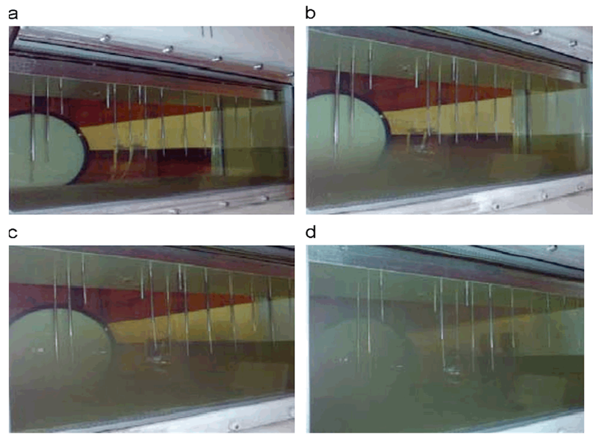
| Clean fuel for jet engines TC-1 | Clean fuel for jet engines Jet A-1 | Fuel for jet engines TC-1 with microbiological pollution | Fuel for jet engines Jet A-1 with microbiological pollution |
 |  |  |  |
| Phylum | JP-8 (n * = 828) | Jet A (n * = 311) | Biodiesel (n * = 61) | Total (n * = 1200) |
|---|---|---|---|---|
| Acidobacteria | 15 | 0 | 0 | 15 |
| Actinobacteria | 85 | 63 | 4 | 152 |
| Bacteroidetes | 5 | 0 | 0 | 5 |
| Chloroflexi | 7 | 0 | 0 | 7 |
| Cyanobacteria | 56 | 0 | 0 | 56 |
| Deinococcus-Thermus | 2 | 0 | 0 | 2 |
| Firmicutes | 83 | 99 | 2 | 184 |
| Gemmatimonadetes | 2 | 0 | 0 | 2 |
| Nitrospira | 49 | 0 | 0 | 49 |
| Plantomycetes | 2 | 0 | 0 | 2 |
| Proteobacteria | 459 | 149 | 55 | 663 |
| TM7 | 1 | 0 | 0 | 1 |
| Verrucomicrobia | 2 | 0 | 0 | 2 |
| Unclassified Bacteria | 57 | 0 | 0 | 57 |
| Unclassified Root | 3 | 0 | 0 | 3 |
| Phylogenetic Classification | JP-8 (n = 828) | Jet A (n = 311) | Biodiesel (n = 61) | Total (n = 1200) |
|---|---|---|---|---|
| Acidobacteria | ||||
| Gpl | 1 | 0 | 0 | 1 |
| Gpl 6 | 4 | 0 | 0 | 4 |
| Gpl 7 | 10 | 0 | 0 | 10 |
| Actinobacteria | ||||
| Actinomyces | 0 | 1 | 0 | 1 |
| Agromyces | 1 | 0 | 1 | 2 |
| Arthrobacter | 2 | 12 | 0 | 14 |
| Corynebacterium | 2 | 0 | 0 | 2 |
| Curtobacterium | 3 | 0 | 0 | 3 |
| Kytococcus | 1 | 0 | 0 | 1 |
| Microbacterium | 6 | 15 | 0 | 21 |
| Mycobacterium | 0 | 7 | 0 | 7 |
| Propionibacterium | 17 | 6 | 1 | 24 |
| Quadrispliaera | 1 | 0 | 0 | 1 |
| Rhodococctis | 40 | 21 | 1 | 62 |
| Rothia | 1 | 1 | 0 | 2 |
| Unclassified Actinomycetales | 6 | 0 | 0 | 6 |
| Unclassified Corynebacterineae | 1 | 0 | 1 | 2 |
| Unclassified Microbacteriaceae | 2 | 0 | 0 | 2 |
| Unclassified Nocardiaceae | 1 | 0 | 0 | 1 |
| Unclassified Rubrobacterineae | 1 | 0 | 0 | 1 |
| Bacteroidetes | ||||
| Cloacibacterium | 1 | 0 | 0 | 1 |
| Hymenobacter | 2 | 0 | 0 | 2 |
| Unclassified Sphingobacteriales | 2 | 0 | 0 | 2 |
| Cliloroflexi | ||||
| Caldilinea | 1 | 0 | 0 | 1 |
| Unclassified Anaerolineae | 5 | 0 | 0 | 5 |
| Unclassified Chloroflexi | 1 | 0 | 0 | 1 |
| Cyanobacteria | ||||
| Streptophyta | 46 | 0 | 0 | 46 |
| Unclassified Cyanobacteria | 10 | 0 | 0 | 10 |
| Deinococcus-Thennus | ||||
| Deinococcus | 1 | 0 | 0 | 1 |
| Truepera | 1 | 0 | 0 | 1 |
| Finnicutes | ||||
| Anaerotruncus | 3 | 2 | 0 | 5 |
| Bacillus a | 0 | 11 | 0 | 11 |
| Bacillus d | 31 | 19 | 0 | 50 |
| Bacillus f | 0 | 1 | 0 | 1 |
| Bacillus h | 8 | 0 | 0 | 8 |
| Clostridium | 0 | 3 | 0 | 3 |
| Staphylococcus | 2 | 43 | 0 | 45 |
| Streptococcus | 1 | 3 | 1 | 5 |
| Unclassified Bacillaceae 2 | 2 | 0 | 0 | 2 |
| Unclassified Bacillales | 1 | 0 | 0 | 1 |
| Unclassified Bacilli | 0 | 0 | 1 | 1 |
| Unclassified Bacillus | 0 | 12 | 0 | 12 |
| Unclassified Clostridiales | 1 | 0 | 0 | 1 |
| Unclassified Riuninococcaceae | 34 | 5 | 0 | 39 |
| Gemmatinionadetes | ||||
| Gemmatimonas | 2 | 0 | 0 | 2 |
| Nitrospira | ||||
| Nitrospira | 49 | 0 | 0 | 49 |
| Planctomycetes | ||||
| Pirellula | 2 | 0 | 0 | 2 |
| Proteobacteria | ||||
| Alphaproteobacteria | ||||
| Bosea | 11 | 0 | 0 | 11 |
| Bradyrhizobium | 2 | 1 | 0 | 3 |
| Brewindimonas | 23 | 0 | 6 | 29 |
| Caulobacter | 0 | 0 | 1 | 1 |
| Hyphomicrobium | 0 | 1 | 0 | 1 |
| Methylobacterium | 46 | 87 | 0 | 133 |
| Phenylobacterium | 0 | 0 | 1 | 1 |
| Rhodocista | 1 | 0 | 0 | 1 |
| Sphingobium | 3 | 0 | 1 | 4 |
| Sphingopyxis | 7 | 0 | 0 | 7 |
| Unclassified Alphaproteobacteria | 3 | 5 | 0 | 8 |
| Unclassified Bradyrhizobiaceae | 1 | 0 | 0 | 1 |
| Unclassified Caulobacteraceae | 3 | 0 | 1 | 4 |
| Unclassified Methydobacteriaceae | 1 | 0 | 0 | 1 |
| Unclassified Phyllobacteriaceae | 1 | 1 | 0 | 2 |
| Unclassified Rhizobiaceae | 0 | 1 | 0 | 1 |
| Unclassified Rhizobiales | 6 | 3 | 0 | 9 |
| Unclassified Rhodospirillaceae | 1 | 0 | 0 | 1 |
| Unclassified Sphingonionadaceae | 3 | 1 | 1 | 5 |
| Betaproteobacteria | ||||
| Acidovorax | 0 | 1 | 0 | 1 |
| Alcaligenes | 1 | 0 | 0 | 1 |
| Aquabacterium | 2 | 0 | 0 | 2 |
| Burkholderia | 24 | 15 | 2 | 41 |
| Comamonas | 6 | 0 | 1 | 7 |
| Cupriawdus | 1 | 0 | 0 | 1 |
| Delftia | 29 | 0 | 1 | 30 |
| Herbaspirillum | 3 | 0 | 0 | 3 |
| Janthinobacterium | 11 | 0 | 1 | 12 |
| Pandoraea | 0 | 5 | 0 | 5 |
| Pelomonas | 1 | 0 | 0 | 1 |
| Ralstonia | 0 | 0 | 1 | 1 |
| Unclassified Alcaligenaceae | 70 | 0 | 29 | 99 |
| Unclassified Bnrkholderiaceae | 11 | 0 | 0 | 11 |
| Unclassified Burkholderiales | 1 | 0 | 0 | 1 |
| Unclassified Comanionadaceae | 1 | 12 | 2 | 15 |
| Unclassified Incertae sedis 5 | 17 | 0 | 3 | 20 |
| Unclassified Oxalobacteiaceae | 1 | 0 | 0 | 1 |
| Unclassified Rhodocyclaceae | 5 | 1 | 0 | 6 |
| Variovorax | 0 | 1 | 0 | 1 |
| Gainniaproteobacteria | ||||
| Acinetobacter | 6 | 0 | 0 | 6 |
| Alkanindiges | 2 | 0 | 0 | 2 |
| Citrobacter | 1 | 0 | 0 | 1 |
| Dyella | 1 | 0 | 0 | 1 |
| Flavimonas | 2 | 0 | 0 | 2 |
| Psendontonas | 91 | 10 | 1 | 102 |
| Shigella | 0 | 1 | 0 | 1 |
| Stenotrophomonas | 6 | 0 | 1 | 7 |
| Unclassified Enterobacteriaceae | 9 | 0 | 0 | 9 |
| Unclassified Gainniaproteobacteria | 5 | 0 | 2 | 7 |
| Unclassified Pseudomonadaceae | 5 | 0 | 0 | 5 |
| Yersinia | 24 | 2 | 0 | 26 |
| Deltaproteobacteria | ||||
| Unclassified Deltaproteobacteria | 2 | 0 | 0 | 2 |
| Epsilonproteobacteria | ||||
| Unclassified Helicobacteraceae | 1 | 0 | 0 | 1 |
| Wolinella | 0 | 1 | 0 | 1 |
| Unclassified Proteobacteria | 8 | 0 | 0 | 8 |
| TM7 | ||||
| TM7 genera Incertae sedis | 1 | 0 | 0 | 1 |
| Vemicomicrobia | ||||
| Subdivision 3 genera Incertae sedis | 1 | 0 | 0 | 1 |
| Xiphinematobacteriaceae genera Incertae sedis | 1 | 0 | 0 | 1 |
| Unclassified Bacteria | 57 | 0 | 0 | 57 |
| Unclassified Root | 3 | 0 | 0 | 3 |
| Microbial Contaminants | JP-4 1958–1966 | Jet A 1988–1997 | Jet A-l 1998–1999 | JP-8 2002 | JP-8 2006 |
|---|---|---|---|---|---|
| Bacteria Acinetobacter (calcoaceticus, cerificans) | - | Yes | Yes | - | - |
| Arthrobacter | - | Yes | - | Yes | |
| Aerobacter aerogenes | Yes | Yes | Yes | - | |
| Aeromonas sp. | - | Yes | Yes | - | |
| Alcaligenes | - | Yes | Yes | - | Yes |
| Breyibacterium ammoniagenes | Yes | Yes | - | ||
| Desulfoyibrio sp. (SRB) Dietzia sp. | Yes | Yes | Yes | - | Yes |
| Escherichia sp. Enterohacter | Yes | Yes | - | - | |
| Flayobacterium (arborescens, diffusum) Kocuria rhizophilia | Yes | Yes | Yes | - | Yes |
| Leucobacter komagatae | - | - | Yes | ||
| Micrococcus sp. | Yes | Yes | Yes | - | Yes |
| Pantoea ananatis | - | - | - | Yes | |
| Streptomyces sp. Staphylococcus sp. | - | - | Yes | - | Yes |
| Sphingomonas Serratia | - | - | Yes | - | Yes |
| Bacillus sp. (acidocaldarius + others) | Yes | Yes | Yes | Yes | Yes |
| Pseudomonas sp. (aeruginosa + others) | Yes | Yes | Yes | ||
| Fungi Acremonium sp. (strictum) | - | Yes | Yes | - | - |
| Aspergillus sp. (niger, fumigatus + others) | Yes | Yes | Yes | - | - |
| Aureobasidium pullulans | Yes | Yes | - | Yes | |
| Candida sp. (famata, lipolytica + others) Discophaerina fagi Exophiala jeanselmei | - | Yes | Yes | Yes | Yes |
| Fusarium sp. (moniliforme + others) | - | Yes | Yes | - | - |
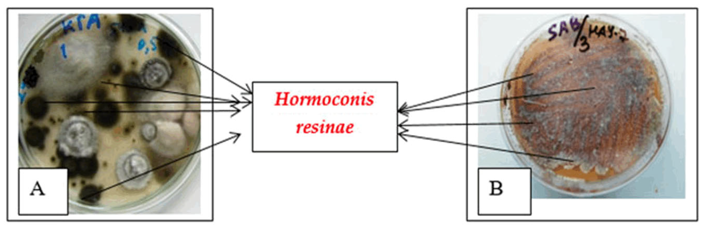
| Hormoconis (Cladosporiuni) resinae | Yes | Yes | Yes | Yes | - |
| Hebninthosporium sp. | Yes | - | Yes | - | - |
| Paecilomyces (yariotii + others) | Yes | Yes | Yes | - | - |
| Penicillium sp. (corylophilum + others) | Yes | Yes | Yes | - | - |
| Phialophora sp. | - | Yes | Yes | - | - |
| Rhinocladiella sp. | - | - | Yes | - | - |
| Rhodotorula sp. | - | Yes | Yes | - | - |
| Trichosporium sp. | - | - | Yes | - | - |
| Tothersrichoderma sp. (yiride + others) | - | Yes | Yes | - | - |
| Microorganism | Microbial Species |
|---|---|
| Fungi | Acremomum sp., Altenaria altenarata, Aspergillus sp., Aspergillus clavatus, Aspergillus flavus, Aspergillus fumigatos, Aspergillus niger, Cladosporium sp., Cladosporium cladosporoides, Fusarium sp., Fusanum moniliforme Fusarium oxysporum Hormoconis resinae Monascus floridanus, Paecilomyces variotii, Penicillium sp., Penicillium cyclioium, Rhinocladiella sp., Trihoderma viride, Trichosporon sp. |
| Bacteria | Acitenobacter, Alcaligehes, Bacillus sp., Clostridium, Sporogenes, Flavobacterium difissum, Micrococcus sp., Pseudomonas sp., Pseudomonas aeroginosa, Serratia marcescens |
| Yeasts | Candida sp., Candida famata, Candida guilliermondii, Candida lipolytica, Rhodotorula sp. |
| Name Quality Indicator | TC-1 | RT | Jet A-l | |||
|---|---|---|---|---|---|---|
| Before Bio Cont. | After Bio Cont. | Before Bio Cont. | After Bio Cont. | Before Bio Cont. | After Bio Cont. | |
| Acidity, mg KOH on 100 sm3 | 0.2 | 6.8 | 0.2 | 6.5 | 0.1 | 6.6 |
| The concentration of actual resins, mg/100 sm3 | 2.5 | 8.7 | 1.8 | 7.6 | 3.8 | 9.8 |
| Testing on copper plate | 1 | 2a | 1 | 2a | 1 | 3a |
| Temperature of crystallization, °C | −61 | −58 | −59 | −50 | −51 | −44 |
| Density 20 °C, kg/m3 | 793 | 791 | 781 | 781 | 779 | 777 |
| Cinematic viscosity, 20 °C, mm2/s | 1.35 | 1.4 | 1.38 | 1.41 | 1.36 | 1.42 |
| Lower combustion heat, kJ/kg | 43.1 | 43.0 | 43.3 | 42.8 | 42.9 | 42.4 |
| Flash point, °C | 34 | 30 | 39 | 33 | 41 | 35 |
| Thermal oxidation stability precipitation rate, mg/100 sm3 | 9 | 15 | 4 | 12 | 3 | 10 |
Disclaimer/Publisher’s Note: The statements, opinions and data contained in all publications are solely those of the individual author(s) and contributor(s) and not of MDPI and/or the editor(s). MDPI and/or the editor(s) disclaim responsibility for any injury to people or property resulting from any ideas, methods, instructions or products referred to in the content. |
© 2024 by the authors. Licensee MDPI, Basel, Switzerland. This article is an open access article distributed under the terms and conditions of the Creative Commons Attribution (CC BY) license (https://creativecommons.org/licenses/by/4.0/).
Share and Cite
Pruski, D.; Sprynskyy, M. Jet Fuel Contamination: Forms, Impact, Control, and Prevention. Energies 2024, 17, 4267. https://doi.org/10.3390/en17174267
Pruski D, Sprynskyy M. Jet Fuel Contamination: Forms, Impact, Control, and Prevention. Energies. 2024; 17(17):4267. https://doi.org/10.3390/en17174267
Chicago/Turabian StylePruski, Daniel, and Myroslav Sprynskyy. 2024. "Jet Fuel Contamination: Forms, Impact, Control, and Prevention" Energies 17, no. 17: 4267. https://doi.org/10.3390/en17174267
APA StylePruski, D., & Sprynskyy, M. (2024). Jet Fuel Contamination: Forms, Impact, Control, and Prevention. Energies, 17(17), 4267. https://doi.org/10.3390/en17174267