Abstract
To investigate the impact of blending natural gas with hydrogen on the combustion performance of partially premixed gas water heaters, a framelet-generated manifold (FGM) was employed for lower-order simulation of combustion processes. Coupled with the 30-step methane combustion mechanism simplified by GRI3.0, a three-dimensional computational fluid dynamics (CFD) simulation of the combustion chamber of a partially premixed gas water heater was carried out. A numerical simulation was performed to analyze the combustion process of a mixture including 0–40% natural gas and hydrogen in the combustion chamber of a partially premixed gas water heater. The results indicate that the appropriate hydrogen blending ratio for some premixed gas water heaters should be less than 20%. Furthermore, it was observed that after blending hydrogen, there was a significant increase in the combustion temperature of the water heater. Additionally, there was a slight increase in NOx.
1. Introduction
In response to the global energy shortage and environmental pollution, there is a growing stringency in regulations regarding the concentration of hazardous pollutants released during energy consumption. The urgency to transition towards renewable energy sources is also increasing. It is crucial to find a solution that meets both development needs and carbon neutrality criteria. Addressing climate change requires a reduction in greenhouse gas emissions, which necessitates replacing carbon-intensive fossil fuels with sustainable and renewable alternatives. Currently, some researchers are utilizing geochemical methods to uncover the formation and evolution of oil and gas, as well as to speculate on their sources and distribution [1]. Strengthening geochemical research not only has the potential to enhance the success rate and efficiency of oil and gas exploration but also to promote the sustainable development and utilization of these resources.
Hydrogen is increasingly recognized as an environmentally friendly energy source due to its zero carbon emissions. The integration of hydrogen into natural gas has proven to be a successful strategy for reducing harmful gas pollutants. Utilizing renewable energy sources like wind and solar power for water electrolysis enables us to produce hydrogen, which can then be combined with existing natural gas reserves. This approach offers residential and commercial consumers the opportunity to fully utilize the storage and transportation capacities within the current natural gas infrastructure [2].
Harmen de Vries et al. [3] conducted a study on the impact of blending natural gas and hydrogen on the operation of terminal equipment. The analysis focused on the combustion of a blend of natural gas and hydrogen from the perspective of combustion theory. The study aimed to examine the impact of this blend on fuel parameters such as the Wobbe index, calorific value, air demand, and laminar combustion speed. The potential influence on standard end-use equipment in this field was inferred and discussed. The study concluded that the maximum limit of hydrogen concentration that can be mixed with natural gas depends on the specific composition of the natural gas to which hydrogen is added. Choudhury et al. [4] conducted experiments to investigate the highest NOx and CO emission levels when burning a mixture of natural gas and hydrogen with a 10% H2 concentration using a low NOx burner. The findings indicate that adding less than 10% H2 to natural gas and their combined combustion does not impact the efficiency of low NOx storage water heaters. Yan Zhao et al. [5] conducted experiments to select a typical top burner and investigate the impact of hydrogen addition on the combustion and cooking efficiency of the burner. The results showed that the natural gas stove surface burner can operate safely and effectively with up to 20% hydrogen added to the fuel, thanks to its inherent suction. It is important to note that the addition of hydrogen can lead to a decrease in polluting emissions. Lin et al. [6] conducted a study to investigate the compatibility of a blend of natural gas and hydrogen with current natural gas infrastructure using one-dimensional Cantera simulation techniques. The findings of the study suggest that it is feasible to operate with a hydrogen concentration of up to 20% and that only minor adjustments to existing facilities are required to accommodate this blend. Yue Xin et al. [7] conducted numerical simulations of the combustion of a natural gas–hydrogen mixture in a gas boiler using a casing swirl burner model. The research revealed that an increase in the volume of hydrogen leads to higher combustion temperatures inside the furnace, an advancement of the peak temperature position, and an acceleration of the combustion rate of the gas. In terms of smoke detection, as the hydrogen blending ratio increases, there is a simultaneous decrease in overall smoke emissions and emissions of CO2 and NOx, while emissions of H2O increase. Jinhua Wang et al. [8] conducted a study on the impact of hydrogen doping on the initial expansion of flames during natural gas combustion. Their research involved a series of experiments and modeling techniques to analyze the effect, and they found that the introduction of hydrogen into natural gas promoted the initial combustion of the mixture. This promotion was attributed to an increase in the molar percentages of O and OH in the mixture. The findings suggest that hydrogen doping has a significant influence on flame expansion dynamics during natural gas combustion. Du et al. [9] conducted a study to investigate the impact of burner structure on hydrogen-rich natural gas using modeling techniques. The results indicated that the use of swirl burners can enhance the stability of combustion flames when mixing hydrogen and natural gas, thereby leading to a reduction in pollutants to some extent. This finding suggests that employing swirl burners has the potential to contribute to mitigating environmental pollution caused by combustion processes involving hydrogen-rich natural gas. Kefu Wang et al. [10] employed CFD modeling techniques to investigate the combustion process of natural gas with a high concentration of hydrogen fuel in the combustion chamber of gas turbines modified for aviation. In addition, they analyzed the impact of adding hydrogen on the combustion properties of the fuel. The research findings suggest that hydrogen—natural-gas mixtures with a hydrogen blending ratio ranging from 30% to 40% are suitable for low-pressure combustion, assuming a constant fuel mass flow rate. Fei Ren et al. [11] conducted a study to investigate the impact of hydrogen addition on the combustion efficiency of natural gas fuel. They utilized a modeling technique with the Chemkin II/Premix program to examine the effects of hydrogen doping, ranging from 0 to 40%, on the laminar combustion properties of C1eC alkane fuel under varying initial temperatures and pressures. The findings indicate that an increase in the hydrogen doping ratio leads to a simultaneous increase in both the calorific value and adiabatic flame temperature of the fuel. Rong song Yan et al. [12] conducted simulation and experimental research to investigate the impact of primary air volume and hydrogen natural gas mixed fuel, as well as secondary air flow rates, on combustion temperature, main free radical content, and combustion pollutants in the burner’s combustion process. The research findings indicate that economic advantages within the context of domestic atmospheric burners are more significantly influenced by the primary air coefficient rather than by increasing the volume of secondary air. Increasing the primary air coefficient results in an increased volume of primary air and fuel mixture, leading to improved combustion performance of atmospheric burners and enhanced combustion efficiency. Rui Zhu et al. [13] conducted experiments and simulations using Fluent software to model the combustion of methane mixed with hydrogen on a swirl gas stove. They analyzed the main air coefficient, combustion temperature, and combustion products. The findings indicate that a blend of hydrogen up to 24% does not pose an elevated risk in terms of fuel utilization, satisfying the criteria for gas interchangeability. Chang Wu et al. [14] conducted a combustion experiment on a stove using a mixture of hydrogen and methane gas. They compared and analyzed the combustion conditions of methane mixed with hydrogen and pure methane combustion. The results demonstrated that as the hydrogen doping ratio increased, the heat burden diminished. The greatest reduction occurred at a rated pressure of 2 kPa, and as the proportion of hydrogen blended with methane increased, the thermal efficiency of the stove also increased. Additionally, levels of CO, NO, and NOx in the combustion flue gas decreased. At a pressure of 2 kPa, the system’s efficiency could increase by up to 2.67%. These findings suggest that blending hydrogen with methane can lead to improved thermal efficiency and reduced emissions in stove combustion systems. Jörg Leicher and colleagues [15] conducted a theoretical analysis to examine the changes in fuel gas characteristics following the introduction of hydrogen into natural gas. The addition of hydrogen can lead to higher combustion temperatures and laminar combustion rates, potentially altering flame position and morphology. Appliances designed for natural gas use may experience several adverse effects, including flashback hazards, compromised operational safety, material degradation, increased NOx emissions, and reduced efficiency. The optimal volume percentage of hydrogen blending for gas boilers to achieve excellent fuel combustibility is 24.7%. Midea and Wane Group have developed and deployed operational gas appliances, including gas stoves, gas water heaters, and gas wall-mounted boilers over a period of three months. The civilian simulation kitchen contains a total of 7 items of gas equipment, comprising 2 water heaters, 2 wall-mounted boilers, and 3 gas burners. For the demonstration, a blend of natural gas and hydrogen was employed with a ratio of 10% hydrogen. The GRHYD project in Dunkirk, France, integrates the generated hydrogen gas directly into natural gas and distributes it to more than 200 houses and HCNG refueling stations for utilization, with a maximum concentration of up to 20%.
While there has been significant research on the combustion properties of hydrogenated compounds derived from natural gas, the investigation into their application in household appliances remains inadequate. Most studies have focused on combustion chambers or burners in gas stoves, leaving many unanswered questions about the use of natural gas mixed with hydrogen in other household gas appliances. The present study involved simulating the combustion process of a mixture of natural gas and hydrogen in the exhaust combustion chamber of a domestic gas water heater. The aim was to examine the influence of hydrogen volume in fuel, ranging from 0% to 40%, on the characteristics of fuel combustion and the performance of emissions.
Due to the high reactivity of hydrogen, it may lead to material degradation and safety issues. Hydrogen doping can impact the lifespan of terminal equipment. The causes of material failure due to the presence of hydrogen or its reaction with metal include hydrogen embrittlement, high-temperature hydrogen corrosion, and hydrogen sulfide corrosion. Metal components in household appliances often react with internal hydrogen or other elements, leading to a decrease in the toughness and plasticity of the metal materials. As a result, the lifespan of household appliances is shortened, and their safety performance is reduced. Based on theoretical research, relevant organizations have conducted a series of hydrogen-doped natural gas combustion test experiments on residential terminals, including residential gas stoves and gas water heaters. This set of experimental data demonstrates that it is feasible to add 20% hydrogen to the tested residential gas terminal without causing significant interference in its practical application.
2. Modeling of Partially Premixed Gas Water Heaters
2.1. Area of Study: Modeling
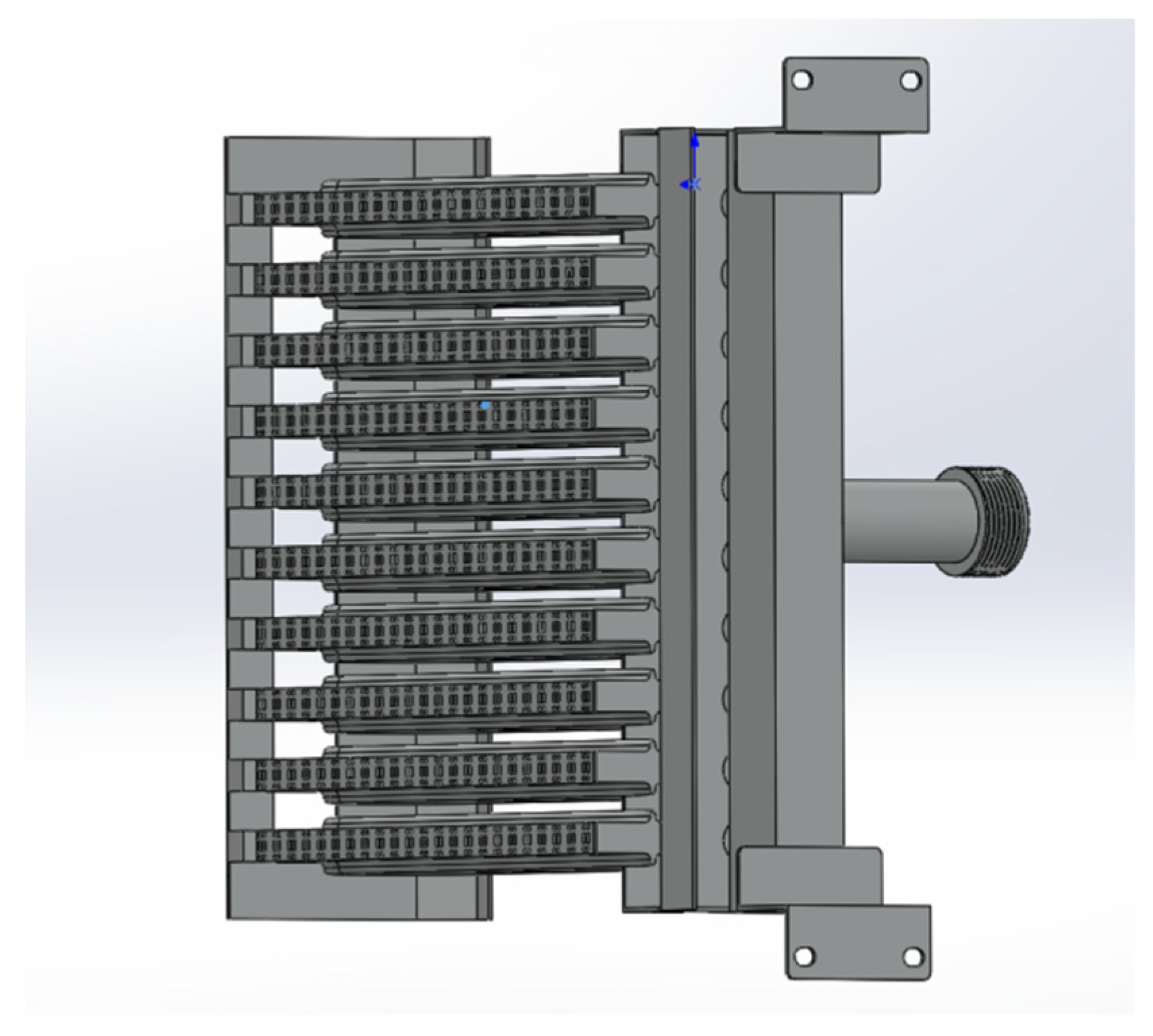
The partially premixed gas water heater is currently one of the primary types of gas water heaters. It addresses certain limitations of the diffusion combustion method by pre-mixing a portion of the air before combustion. This technology improves the efficiency and performance of gas water heaters, making them more effective in providing hot water for residential and commercial use. This advancement has significantly enhanced the functionality and practicality of gas water heaters, thereby meeting the increasing demand for reliable hot water supply in both residential and commercial settings. This enhances the speed of combustion and reduces the occurrence of incomplete combustion. The role of premixed combustion is crucial in optimizing the utilization of gas resources, leading to the conservation of resources and reduced emissions of pollutants [16]. Therefore, the objective of this study is to conduct numerical simulation research on the fire exhaust combustion chamber of specific partially premixed gas water heaters. The aim is to compare the results of numerical simulations with the empirical findings documented in the literature. The combustion chamber model of the gas water heater was utilized to simulate the variations in combustion performance resulting from different amounts of integrated hydrogen gas. In this study, the numerical simulation results are compared with Li Haimen’s experimental results on the selection of premixed gas water heaters [17]. The literature experiment involves the use of thermocouples to measure the temperature at the junction where the outlet of the combustion chamber meets the inlet of the heat exchanger. This measurement is taken at a specific location, precisely 270 mm above the fire hole plane, which is located at the front center of the gas water heater’s combustion chamber. The positioning of the measurement point depends on the depth at which the thermocouple is inserted, resulting in temperature measurements at 1 cm intervals along the X-axis. A combustion chamber model was utilized to simulate the combustion process of natural gas and then compared to experimental findings documented in the existing literature. Figure 1 depicts a burner configuration for a partially premixed water heater.
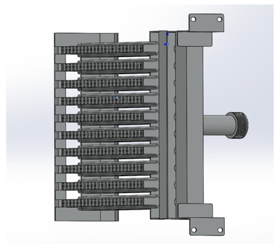
Figure 1.
The burner configuration of a partially premixed water heater.
2.2. Research Area: Mathematical Models
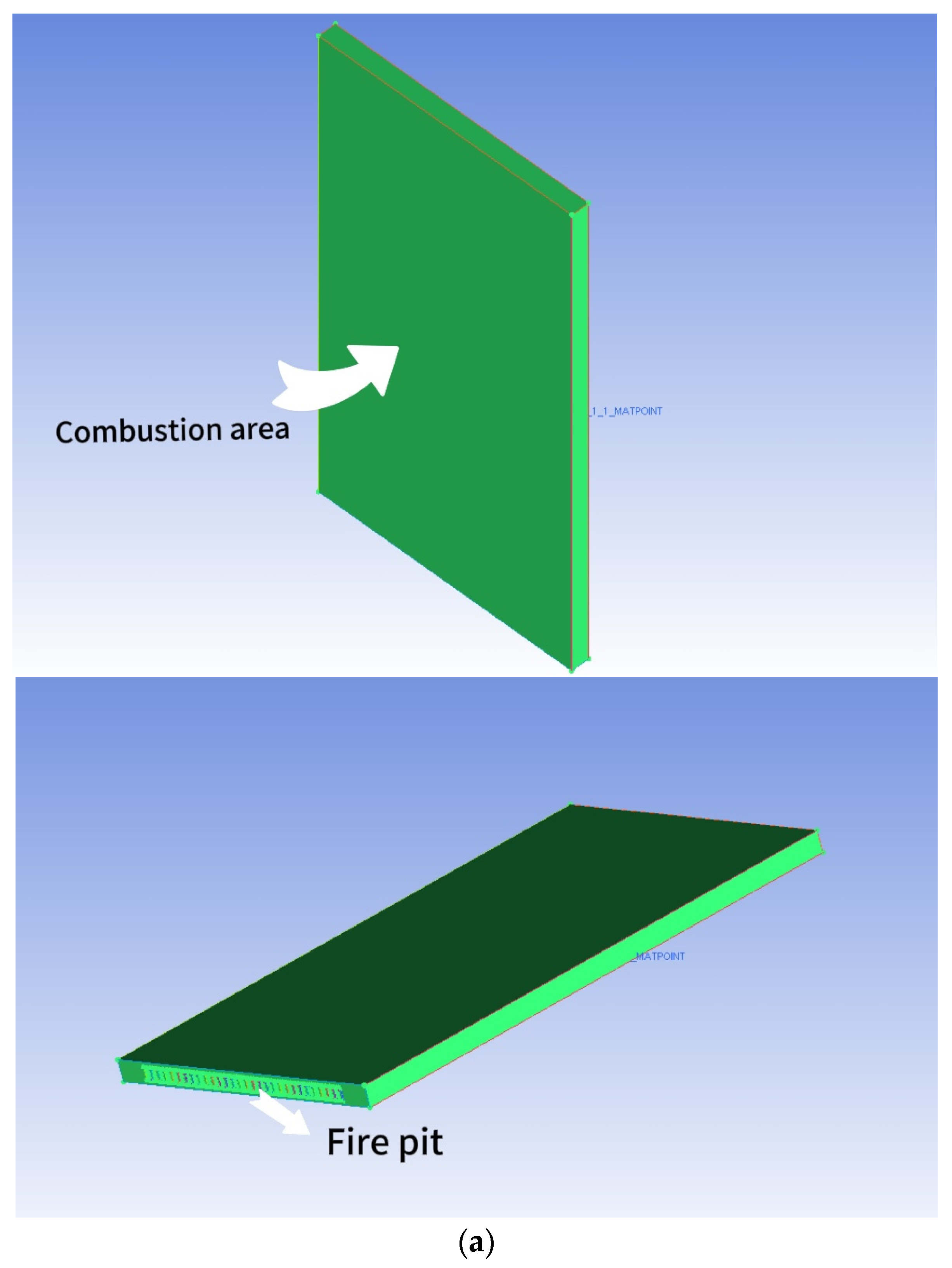
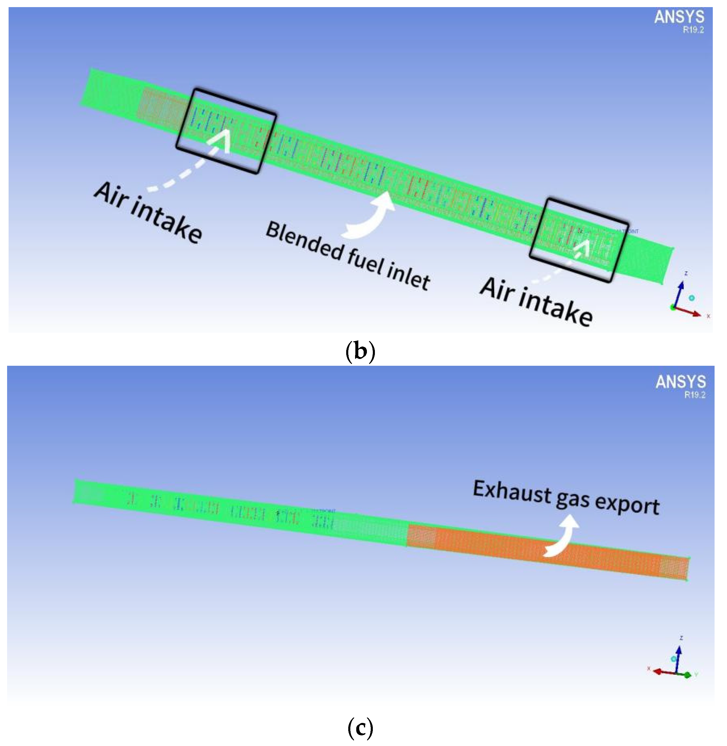
The dimensions of the combustion chamber are as follows: length (d) = 150 mm, height (h) = 270 mm, and width (d1) = 100 mm. The structure exhibits perfect symmetry. The arrangement of the fire holes at the bottom of the chamber mirrors that of the fire exhaust burners. The distance between each fire exhaust burner is 7 mm. The combustion chamber consists of a total of 9 rows of burners, creating a combustion space above the burner. Figure 2a depicts the geometry of the combustion chamber and the simulated area, simplifying the model. The reason for this is that all fire exhaust burners share the same structure. To enhance computational efficiency, only a single row is selected for simulation. The calculation method employs a double precision solver to minimize the significant inaccuracies that result from the pre-index factor and chemical energy of the reaction rate. This study initially simulates the spread of a small flame within FGM. The FGM combustion model utilized is a flame-like surface combustion model, often described as a series of one-dimensional flame surfaces generated from laminar flame surfaces [18]. These one-dimensional surfaces are used to represent turbulent flames in high-dimensional spaces. The utilization of probability density functions (PDFs) for analyzing the interaction between turbulence and chemistry constitutes a chemical mapping method. This approach not only preprocesses the combustion database to enhance computational efficiency but also employs a detailed chemical reaction mechanism for simulating and predicting emissions and the combustion process. Additionally, it enables the simulation and prediction of emissions and combustion processes by utilizing complex chemical reaction mechanisms.
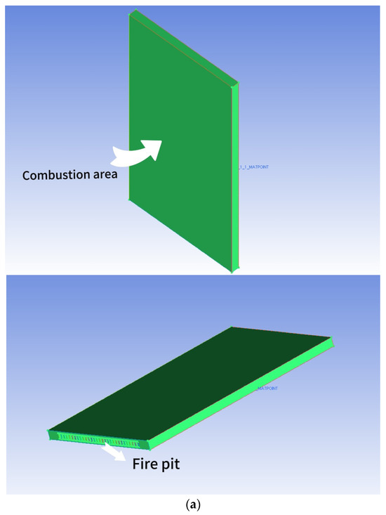
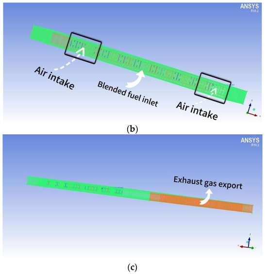
Figure 2.
(a) The combustion chamber of a gas water heater that utilizes partially premixed fuel; (b) Meshing of the combustion chamber of a partially premixed gas water heater (inlet); (c) The grid division (outlet) of the combustion chamber of a partially premixed gas water heater.
Based on GRI 3.0, a simplified simulation of the combustion process of hydrogen additives in the burner chamber of a water heater was conducted. This simplification typically involves approximately 30 major reaction steps, which describe the process of fuel molecules (e.g., methane CH4) reacting with oxygen O2 to produce a series of intermediate and final products, including carbon monoxide CO, carbon dioxide CO2, water H2O, and small amounts of nitrogen oxides NOx. Although this simplified model reduces many detailed reactions in early complex mechanisms, it still captures key chemical steps for rapidly assessing combustion performance, emission characteristics, and combustion stability. According to the literature [13], hydrogen combustion technology for natural gas was applied to domestic swirl gas stoves, and the detailed combustion mechanism of GRI-Mech3.0 was simplified through numerical simulation. Subsequently, the simulation results of the simplified GRI3.0 mechanism were compared with those of the original mechanism. The results indicate that the calculation error between the simplified and detailed mechanisms is less than 1%. Additionally, simplified models have the potential to reduce computational time and improve research efficiency.
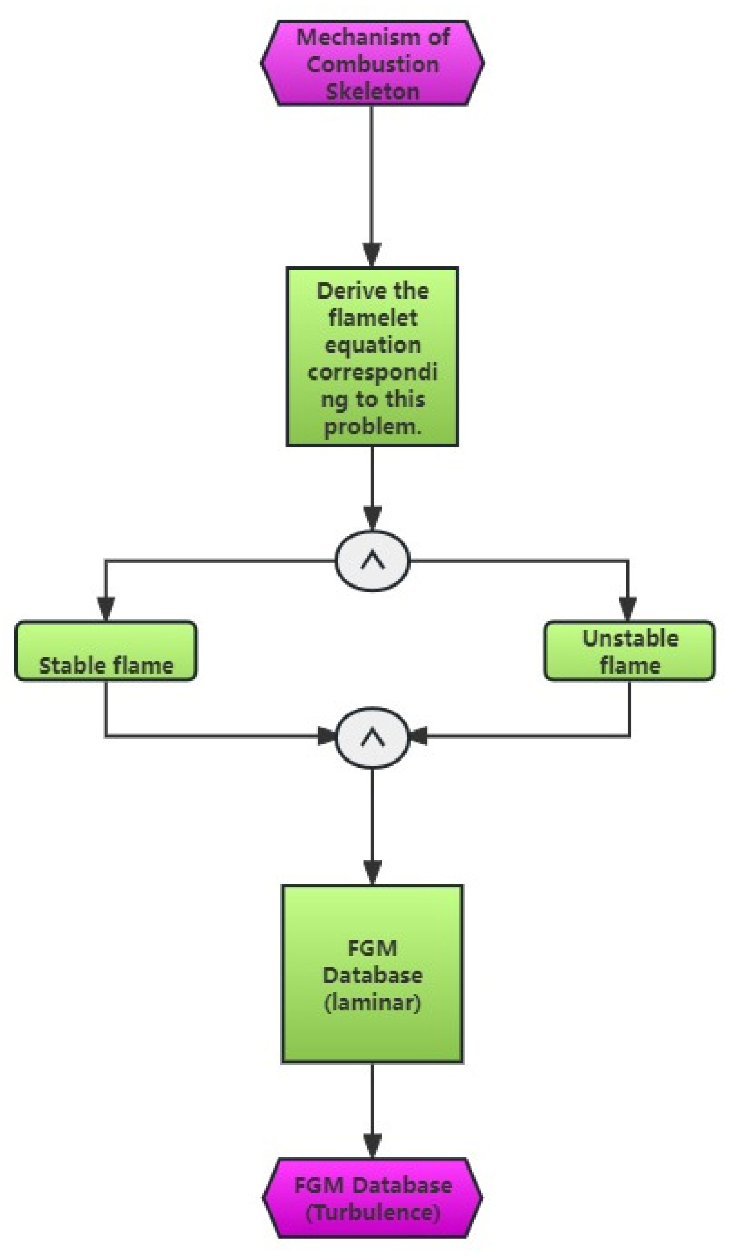
The partially premixed combustion model integrates statistical averages of laminar flame surfaces, FGM tabulation, and hypothetical PDF to accurately depict the impact of turbulence and chemical reaction processes. The depiction is presented in Figure 3, which illustrates the flow chart of the FGM model-solving strategy. The modeling comprises three primary components [19]:
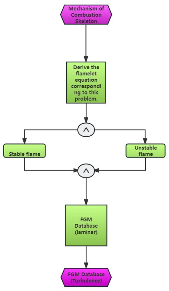
Figure 3.
Flow diagram illustrating the solving approach of the FGM model.
- (1)
- The laminar flow FGM table was developed using the FGM method and a chemical reaction mechanism.
- (2)
- Integrating the laminar flow FGM table with the hypothetical PDF yields the turbulent FGM table.
- (3)
- The turbulent FGM table that was produced was incorporated into the CFD program for computation. The representation of any physical quantity in laminar combustion can be expressed as a PDF that combines mixed fractions and process variables. This PDF can be derived using the following formula:
The primary benefit of utilizing the what-if PDF is the ability to perform chemical reaction calculations and flow field calculations independently, resulting in significant time savings for the flow field calculation. This study employs a theoretical PDF method and assumes that the process variables and mixed scores are mutually independent. The mean PDF of Faver is calculated as follows:
The process variables and mixed fractions are distributed according to beta probability density functions (PDFs). Specifically, the PDFs of the process variables are determined by their average and pulsation, while the PDFs of the mixed fractions are derived by solving their respective transport equations.
The governing equations for the premixed combustion model in this section ultimately consist of four:
The transport equation is as follows:
The equation is as follows:
The transport equation is as follows:
The laminar diffusion coefficient, represented as D, is generally considered to be insignificant in comparison to the turbulent diffusion coefficient. D is typically small and has minimal impact. The relationship between the turbulent viscosity coefficient and the turbulent Schmidt number is commonly regarded as 0.85. Model constants of 2.86 and 2.0 correspond to parameters in Fluent ver. 19.2 [20].
Generation of Turbulent FGM Table: The laminar FGM table is obtained by assuming PDF integration, which includes blending fractions , Me actional Second Moment , Process variables , Process Second Moment , density, temperature, process variables, chemical reaction rate terms and the chemical reaction rate term in the transport equation , information as the component mass fraction. , , , is the free variable. When calculating, the FGM table was queried [15] using these four variables to obtain information such as chemical reaction rate, density, temperature, etc., after convergence, and the distribution of flow field components was obtained by querying the turbulence FGM table.
The process variable chemical reaction rate is calculated using the following equation:
For the chemical reaction rate term in the transport equation , the calculation method is similar:
Among them, the Reynolds average density can be calculated by the following equation:
2.3. Methods of Calculation and Verification through Simulation
This article utilizes a simplified combustion mechanism to computationally simulate the process of methane burning. The computational domain is defined as a combustion chamber for flame exhaust, with dimensions of 150 mm in length, 270 mm in height, and 10 mm in breadth.
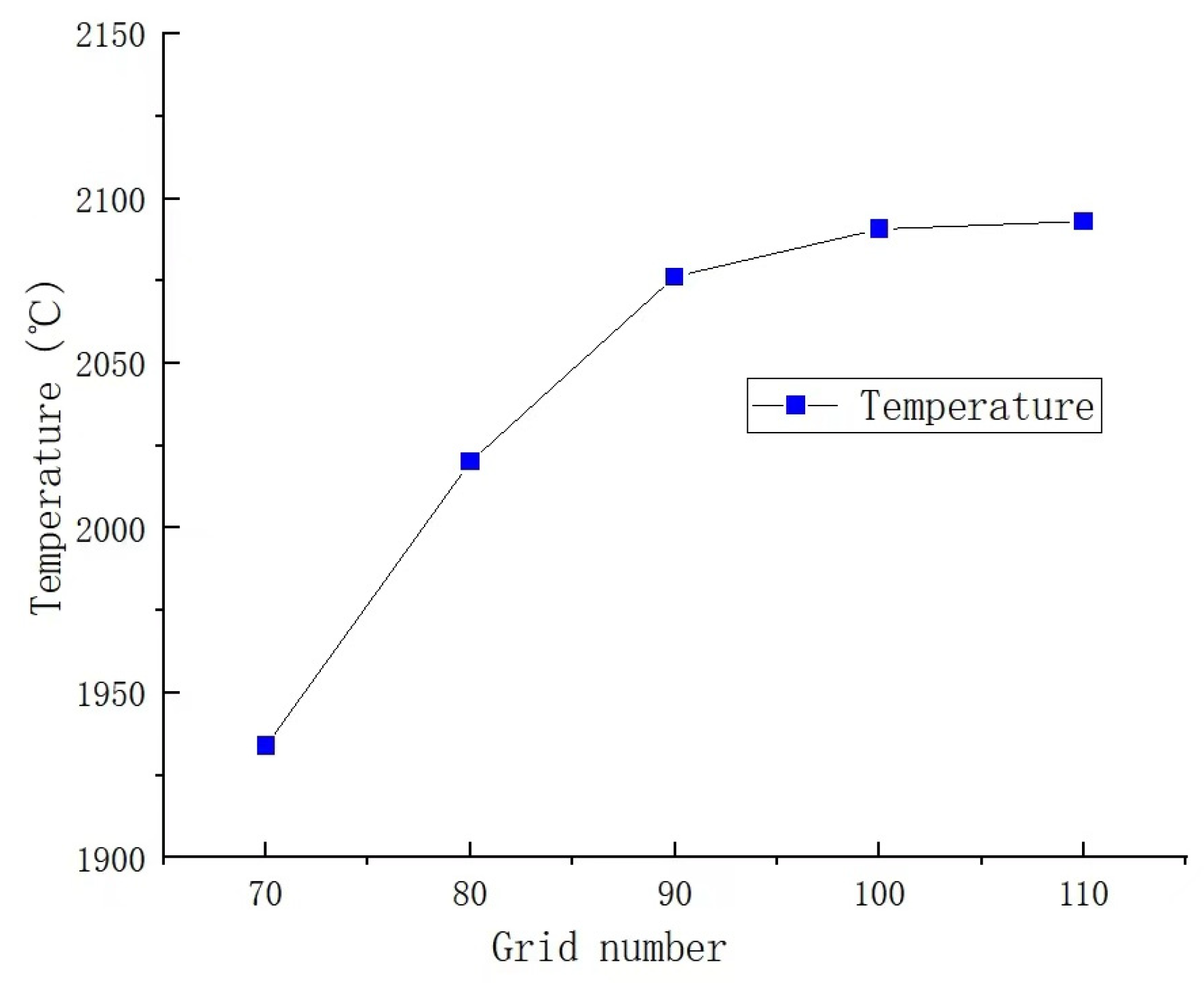
In the simulation of partial premixed combustion, the accuracy of calculation results is influenced by both the number and quality of grids used in the simulation. Therefore, it is crucial to validate grid independence to improve computational efficiency and ensure the accuracy and reliability of calculation results [21]. In this study, mesh refinement is performed at the combustion chamber’s fire hole, where fuel ignition occurs and temperatures reach their peak. By comparing temperatures, the appropriate number of grids is determined. The number of grids is 721,168; 819,168; 917,168; 1,015,186; and 1,131,168, respectively. The comparison results are illustrated in Figure 4. It can be observed from the figure that significant temperature changes occur when the grid is less than 900,000. When the number of grids exceeds 900,000, the temperature at the monitoring points remains stable, with a change rate of less than 1%, indicating a high level of calculation accuracy. Considering the accuracy and efficiency of the calculation results, a total of 1,015,186 grids are utilized in this study, which fulfills the calculation requirements. As shown in Figure 5, the grid quality is outstanding.
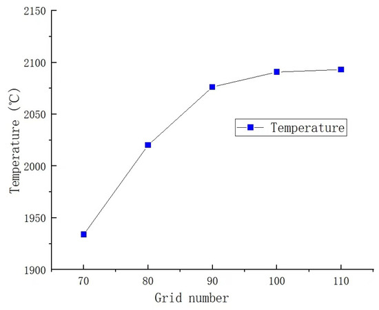
Figure 4.
Temperature changes with the number of grids.

Figure 5.
Grid quality diagram.
Turbulence is characterized by irregular flow, with its physical properties constantly changing. Therefore, to investigate turbulent flow phenomena, it is essential to utilize a turbulence model for simulating this intricate motion.
The Realizable model is employed within the k-epsilon turbulence model for the simulation calculations. The rationale for selecting this turbulence model lies in its suitability for specialized flows such as jet, high swirl flow, separated flow, and separated boundary layer. This is consistent with the characteristics of the jet and high-speed flow demonstrated by our gas water heater.
Moreover, this model offers a more accurate prediction of the divergence ratio in turbulent flow processes and demonstrates superior performance in the calculation of rotating flow and flow separation. This simulation utilizes the Realizable model of the k-epsilon turbulence model for calculations and incorporates improved wall treatment. The Coupled algorithm is employed to couple velocity and pressure for more accurate results.
2.4. Boundary Conditions and Calculation Conditions Setting
As a household appliance, the water heater efficiently heats water to fulfill people’s bathing and cleaning needs. This essential function ensures that individuals have access to hot water for personal hygiene and domestic sanitation purposes. The rated power of a typical household gas water heater ranges from 17 kw to 40 kw. In this study, we conducted a simulation of the combustion chamber and selected an input value with a rated power of 20 kw. The mass flow rate of fuel and oxidizer is calculated based on the designed hydrogen blending ratio, using the rated air quantity while keeping the output power unchanged. During the simulation, the fuel and air inlets are set to mass flow, and the outlet is defined as the pressure outlet boundary condition to ensure that the actual domestic gas water heater does not exceed its rated power. Detailed working conditions are presented in Table 1.

Table 1.
The setting of working conditions under different hydrogen blending ratios.
2.5. Validation of Simulation
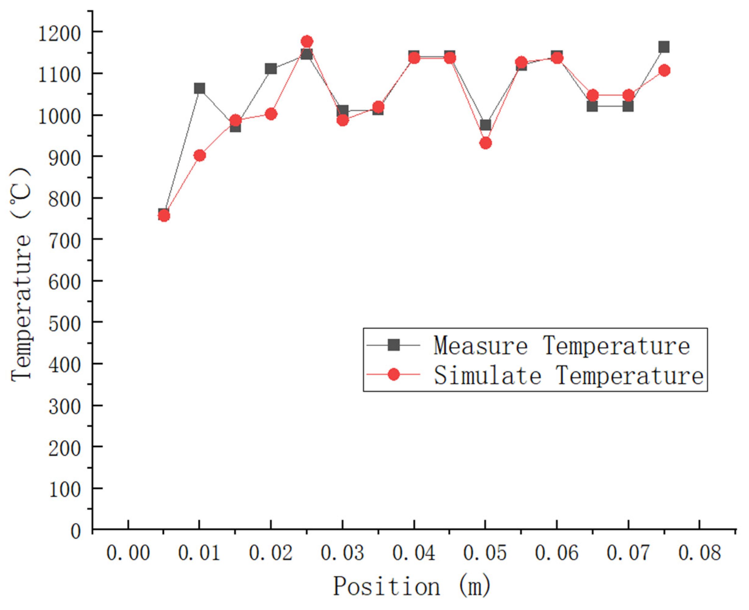
To evaluate the feasibility of numerical simulation, both numerical simulation and physical experiments were employed to assess the temperature of combustion in the exhaust combustion chamber. In a study, Li Haomin [17] investigated the variation in combustion temperature of pure methane in the combustion chamber of a premixed gas water heater and compared the simulation results with the experimental findings.
The literature presents a comparison of the test results for the combustion chamber thermocouple temperature at Z = 45 mm with the simulation results, as shown in Figure 6. The experimental findings reveal that the highest temperature recorded is 1146 °C, and the lowest temperature is 761 °C. In contrast, the simulated peak temperature is 1138 °C, and the lowest temperature is 758 °C. As shown in Table 2: The relative error between the simulated maximum temperature and the experimental results is 0.35%, while for the simulated minimum temperature, it is 0.3%. It can be observed that most of the errors fall within the range of 0–5%, with an average error of 2.48%. This indicates a similarity in trend between the experimental values and simulated values. Additionally, it was observed that higher temperatures were mainly concentrated in the rear area of the combustion chamber, where a slight increase in temperature was noted. These findings demonstrate that numerical simulation produces accurate and reliable results.
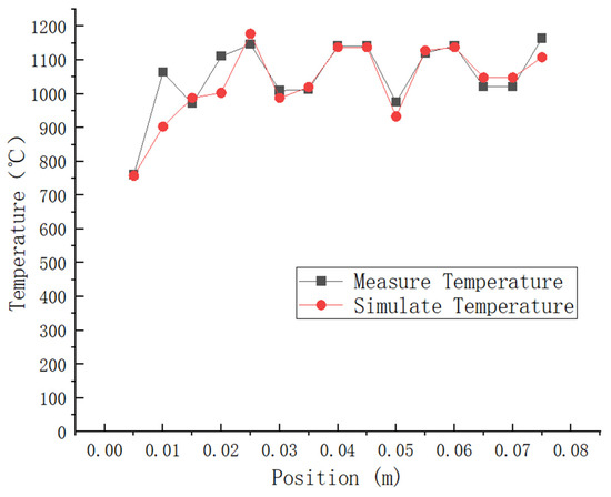
Figure 6.
Thermocouple test temperature data and simulation results at a distance of Z = 45 mm in the combustion chamber are compared.

Table 2.
Comparison of flue gas thermocouple test temperature and simulated temperature at z = 45 mm in the combustion chamber.
3. Analysis of Natural Gas and Hydrogen Combustion Outcomes
Household combustion equipment is designed according to specific gas compositions. When hydrogen is mixed with natural gas, the gas composition changes, and as a result, the combustion conditions of the burner will also change accordingly. This may reduce the combustion efficiency of the equipment and could potentially disrupt its normal operation. Therefore, when hydrogen is mixed into natural gas, its compatibility must be carefully considered to ensure proper functioning. Interchangeability is typically assessed using two primary parameters: the Wobbe number and combustion potential. The natural gas distributed in most regions of China conforms to the 12T natural gas category as defined in the ‘Urban Gas Classification and Basic Characteristics’ (GB/T 13611-2018) standard. We utilize the high calorific value, high Wobbe number (heat load parameter), and combustion potential (combustion velocity parameter) of 12T natural gas as the criteria for assessing the interchangeability following hydrogen blending to determine the maximum proportion of hydrogen in natural gas. When the hydrogen blending ratio meets the gas interchangeability requirements, there is no need for the end user to replace the gas burner, thus avoiding additional replacement costs [22]. For this simulation, we investigated hydrogen doping ratios of 0%, 10%, 20%, 30%, and 40%.
3.1. Impact of Hydrogen Blending Ratio on Combustion Temperature and Stability
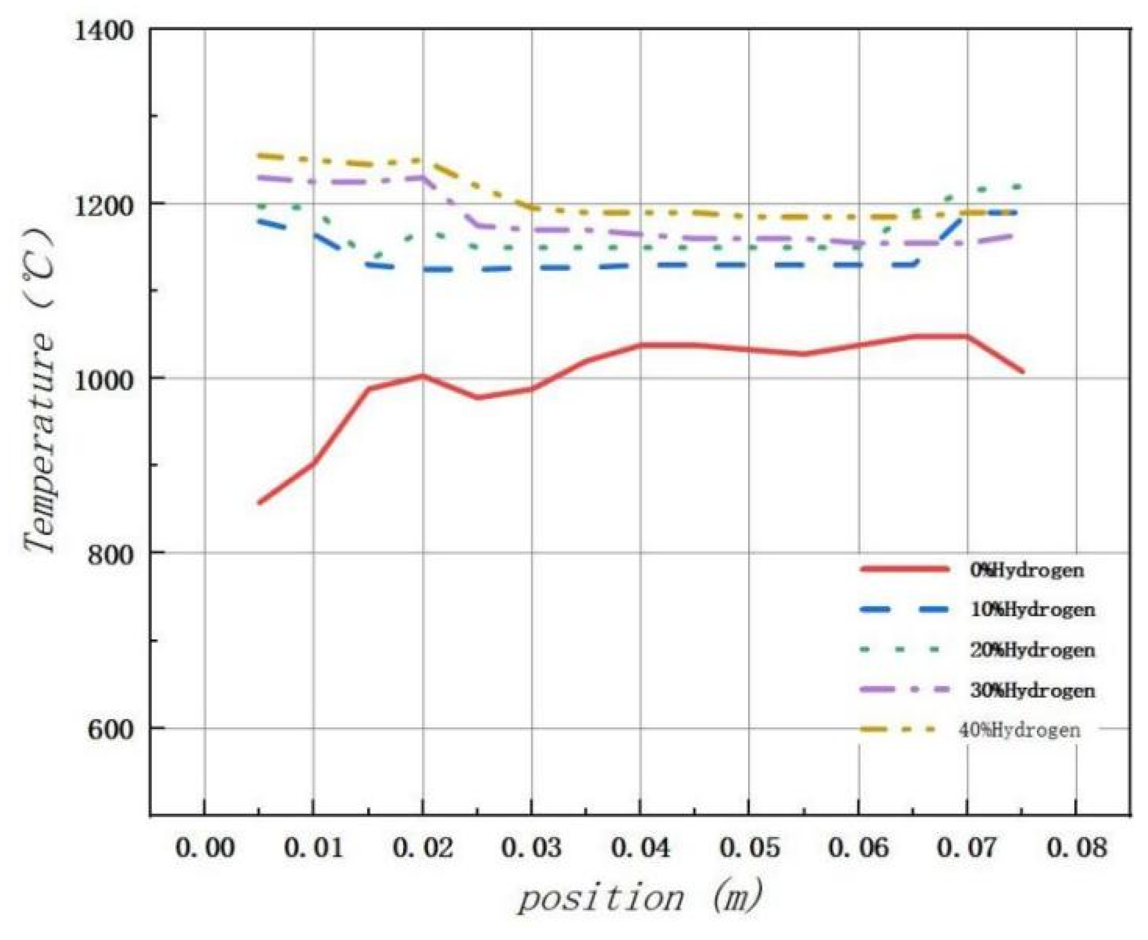
Temperature plays a critical role as the key parameter in combustion reactions, directly influencing both the combustion process and the rate of chemical reactions. The temperature distribution in the combustion chamber was analyzed under different hydrogen doping conditions, and the comparison results are presented in Figure 6. Temperature data were collected in the range of z = 0.03 m, y = 0 m, and x = 0–0.075 m within the combustion chamber. The research indicates that if the hydrogen allocation ratio does not exceed 40%, the combustion potential and Wobbe number can remain relatively stable compared to the natural gas reference gas with a value of 12 T. Therefore, we believe that interchangeability can be achieved when the hydrogen doping ratio is not more than 40%.
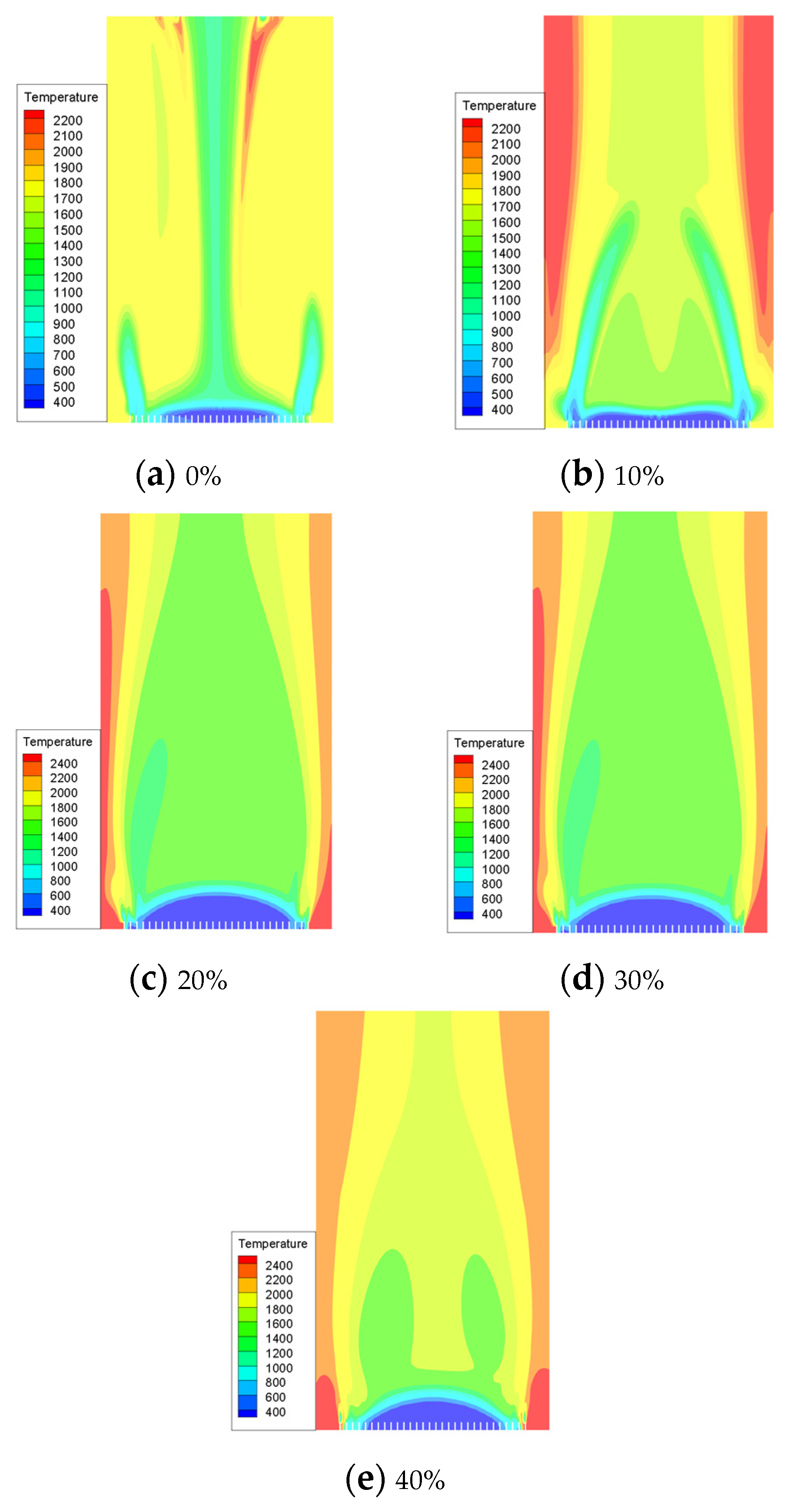
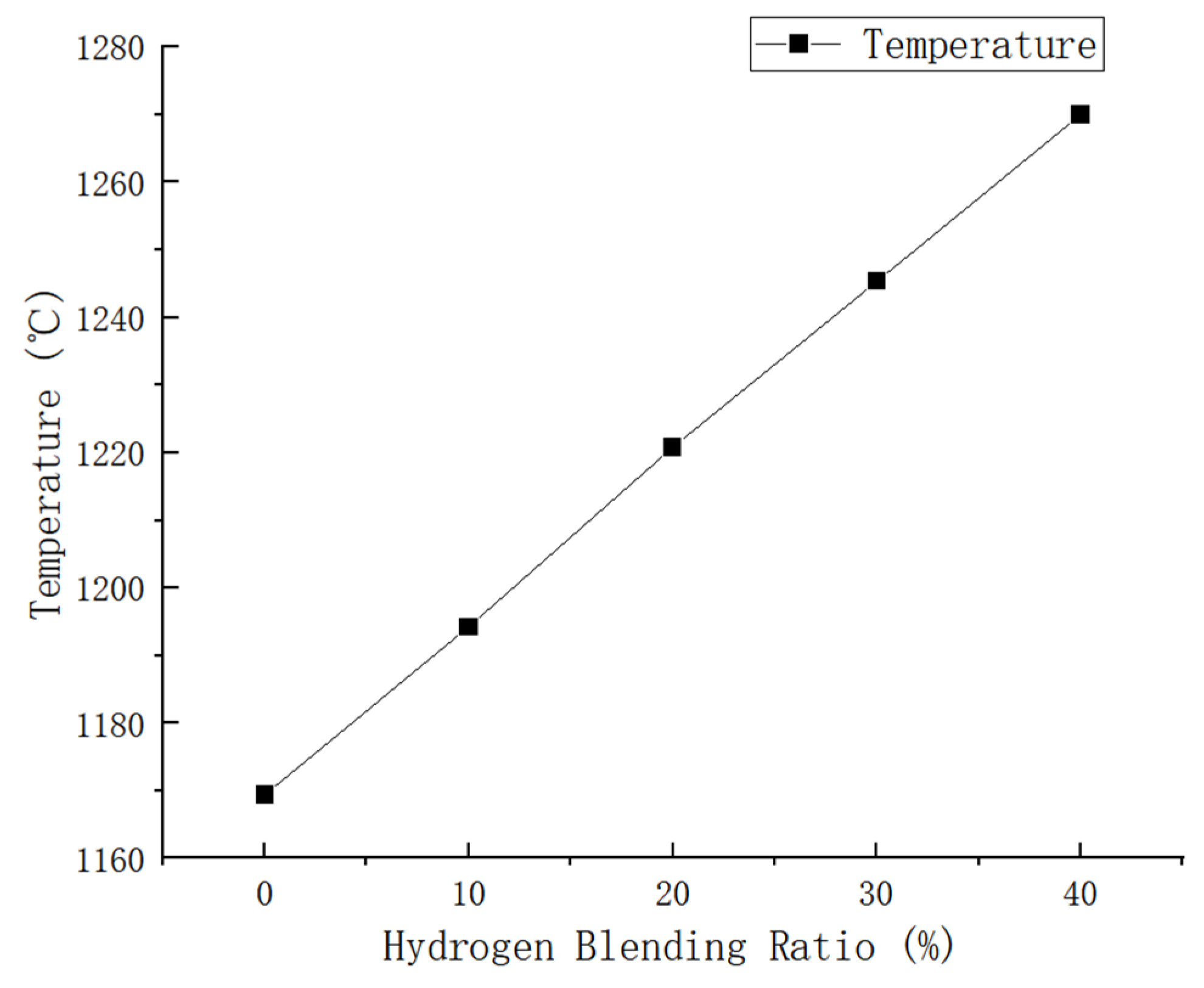
In our simulation, we utilized pure methane and hydrogen with varying blending volume fractions (0%, 10%, 20%, 30%, 40%). The maximum temperatures achieved in the combustion chamber were as follows: 1169.399 K, 1194.274 K, 1220.79 K, 1245.308 K, and 1269.996 K for each respective blending volume fraction. Through cloud image observation, it was found that the flame combustion zone of pure methane combustion is concentrated in the front of the blending hole. The combustion process is rapid, leading to a quick rise in temperature and a long flame length. With the increase in hydrogen proportion, the combustion speed of the fuel at the blending hole accelerates, leading to an instantaneous rise in temperature and expansion of the high-temperature area. This results in a more concentrated flame. In contrast, in the absence of hydrogen, the flame temperature gradually increases from the fuel nozzle to the outside and then tends to be gentler. The introduction of hydrogen leads to a slight temperature change in the combustion chamber. After the introduction of hydrogen, there is a rapid rise in temperature at the fuel inlet, followed by a slight decrease and eventual stabilization. However, it is important to note that even after stabilization, the temperature remains higher than the maximum temperature observed without the presence of hydrogen. As shown in Figure 7, there is a noticeable change in flame temperature in the combustion chamber under different hydrogen ratios. It can be seen that the combustion temperature in the combustion chamber increases with an increase in hydrogen volume. Specifically, when the hydrogen volume reaches 10%, the combustion temperature is 2.1% higher than that of pure methane. Furthermore, with an increase in the hydrogen volume to 20%, the combustion temperature increases by an additional 2.2% compared to the 10% hydrogen blending ratio. Under the condition of a 30% hydrogen blending ratio, the combustion temperature is 2.0% higher than that of a 20% hydrogen blending ratio. Additionally, under the condition of a 40% hydrogen blending ratio, the combustion temperature is 1.9% higher than that of a 30% hydrogen blending ratio.
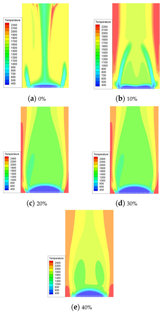
Figure 7.
The influence of hydrogen volume fraction on the overall distribution of temperature.
Based on the analysis of Figure 8, it can be concluded that as the hydrogen blending ratio increases, there is a uniform increase in combustion temperature within the combustion chamber. The maximum temperature increases from 1169.399 K to 1269.996 K because of the increase in the hydrogen blending ratio, leading to an increase in the laminar flame propagation speed. Consequently, if the gas flow rate is lower than the flame propagation speed, it may lead to the occurrence of a backfire phenomenon.
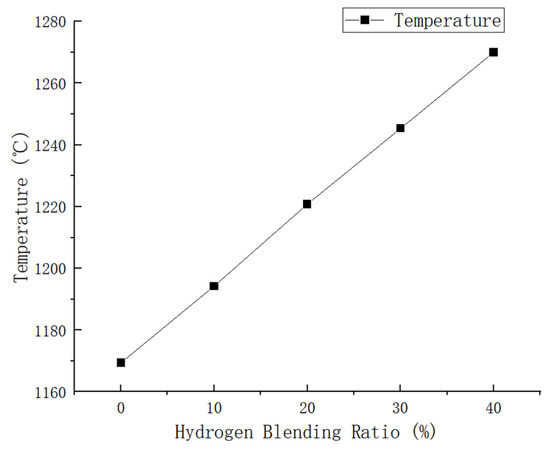
Figure 8.
Influence of hydrogen-doped volume percentage on temperature distribution inside the combustion region.
As illustrated in Figure 9, after adding hydrogen, the temperature change in the combustion chamber becomes more stable compared to pure methane combustion. In particular, when the hydrogen addition ratio is 20%, the combustion process is most stable and uniform, with improved safety performance.
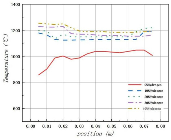
Figure 9.
The impact of the hydrogen-doped volume percentage on the temperature distribution within the combustion chamber.
Hydrogen can react rapidly with oxygen due to its high combustion rate and low ignition energy, thus accelerating the chemical reaction rate of combustion. This acceleration results in the advancement of the combustion process, enabling stable combustion to be maintained at a reduced gas flow rate. Additionally, hydrogen blending not only increases the combustion temperature but also optimizes the entire combustion process by accelerating the chemical reaction rate and combustion transfer rate. This has a positive effect on improving energy efficiency and reducing environmental pollution.
3.2. Analysis of Products Resulting from Hydrogen-Doped Combustion
In response to the country’s increasing focus on environmental protection in recent years, there has been a heightened emphasis on reducing pollutant emissions from gas water heaters. Consequently, emission control strategies for water heaters, as one of the main household appliances, have shifted from solely focusing on carbon emissions to also including nitrogen oxide (NOx) control as a primary objective.
During the combustion process of natural gas, the main source of NOx is thermal NOx, with fast NOx formed through the mechanism of N2O intermediate. Considering that thermal NOx accounts for 90% of total emissions, special attention should be paid to studying the impact of hydrogen-enriched natural gas on thermal NOx. Due to the high temperature in the combustion flame leading to the decomposition of atmospheric N2 and O2 into atomic N and O, which then react to form NO, it is necessary to focus on NO as a key component in this context.
The simulation experiment is divided into five groups, with the gas flow rate and pressure being kept constant. The simulated hydrogen blending ratios are 0%, 10%, 20%, 30%, and 40%, respectively.
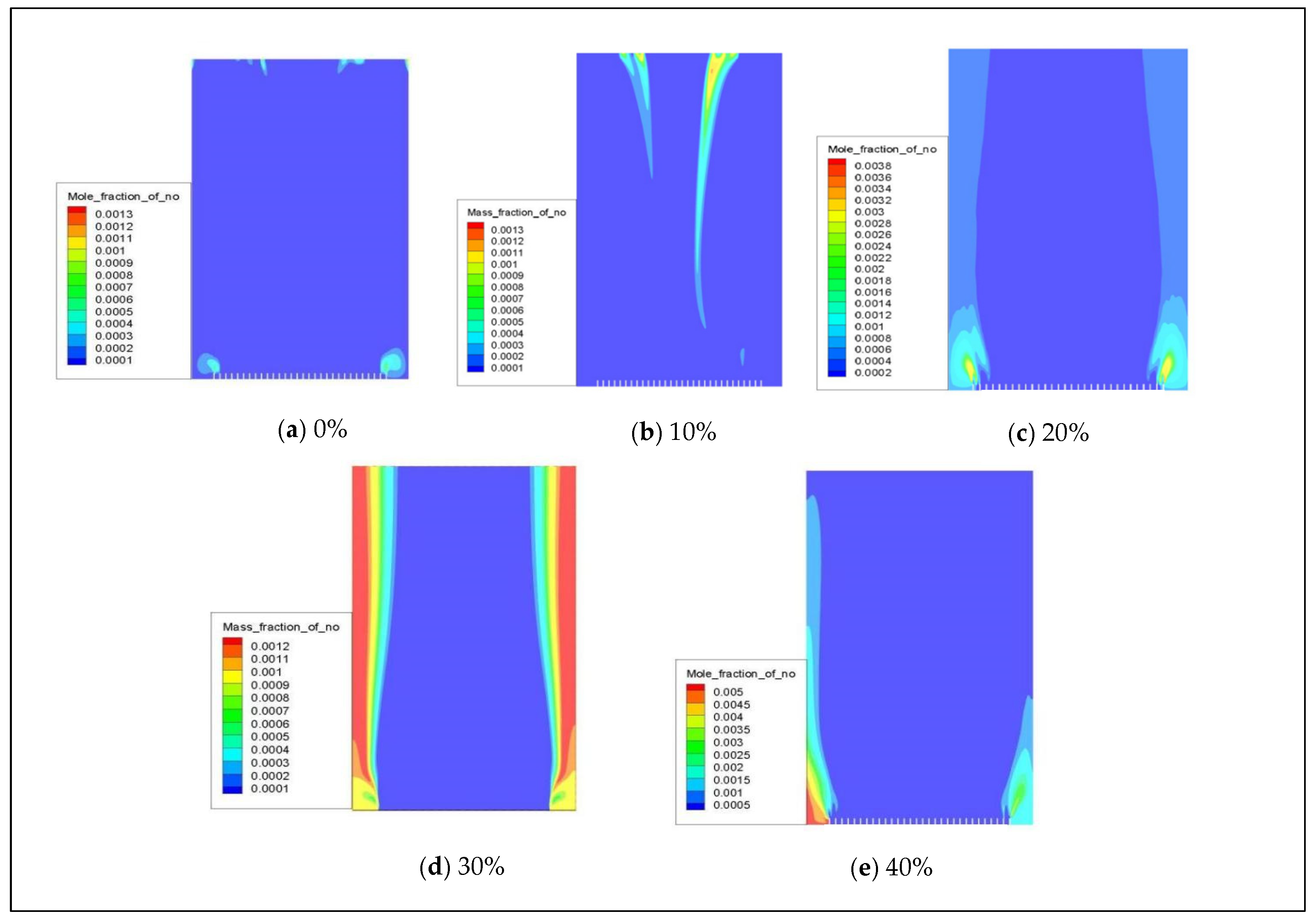
When natural gas is combined with hydrogen, the distribution of NOx (primarily for NO) in a combustion chamber with 0–40% hydrogen volume is depicted in Figure 10. The cloud diagram shows that NO is mainly concentrated at the fuel inlet, and there is a slight increase in NO emissions as the hydrogen blending ratio increases.
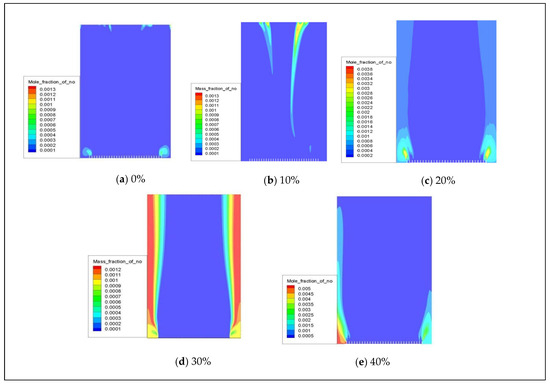
Figure 10.
The influence of hydrogen volume fraction on the overall distribution of NO.
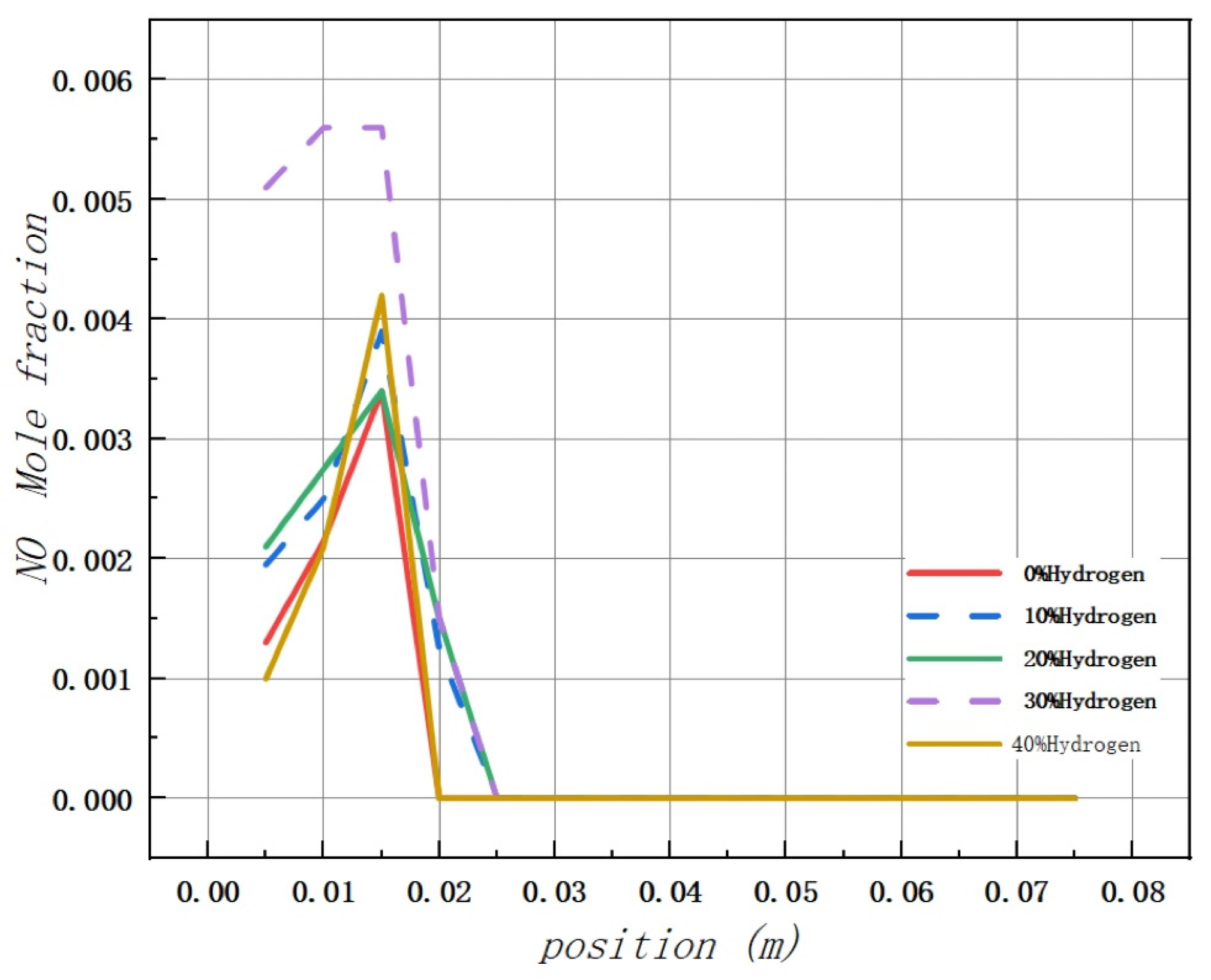
Based on the analysis of Figure 11, it is observed that the addition of hydrogen leads to a peak concentration of NO in the combustion chamber occurring at 0.015 m from the inlet, regardless of the volume used. The maximum values of NO mole fraction in the combustion chamber are 0.0034, 0.0039, 0.0038, 0.0056, and 0.0042, respectively.
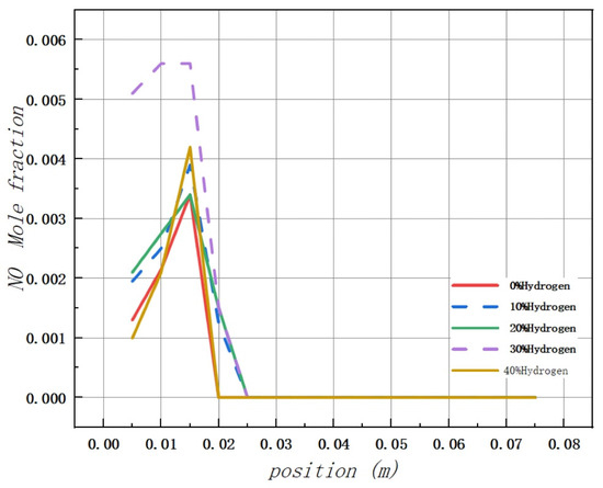
Figure 11.
Influence of hydrogen doping volume fraction on the distribution of NO in the combustion chamber.
Additionally, there is no evidence of NO formation in the middle and rear areas of the combustion chamber.
The main reason for this phenomenon is attributed to the strong correlation between the generation of NO and temperature.
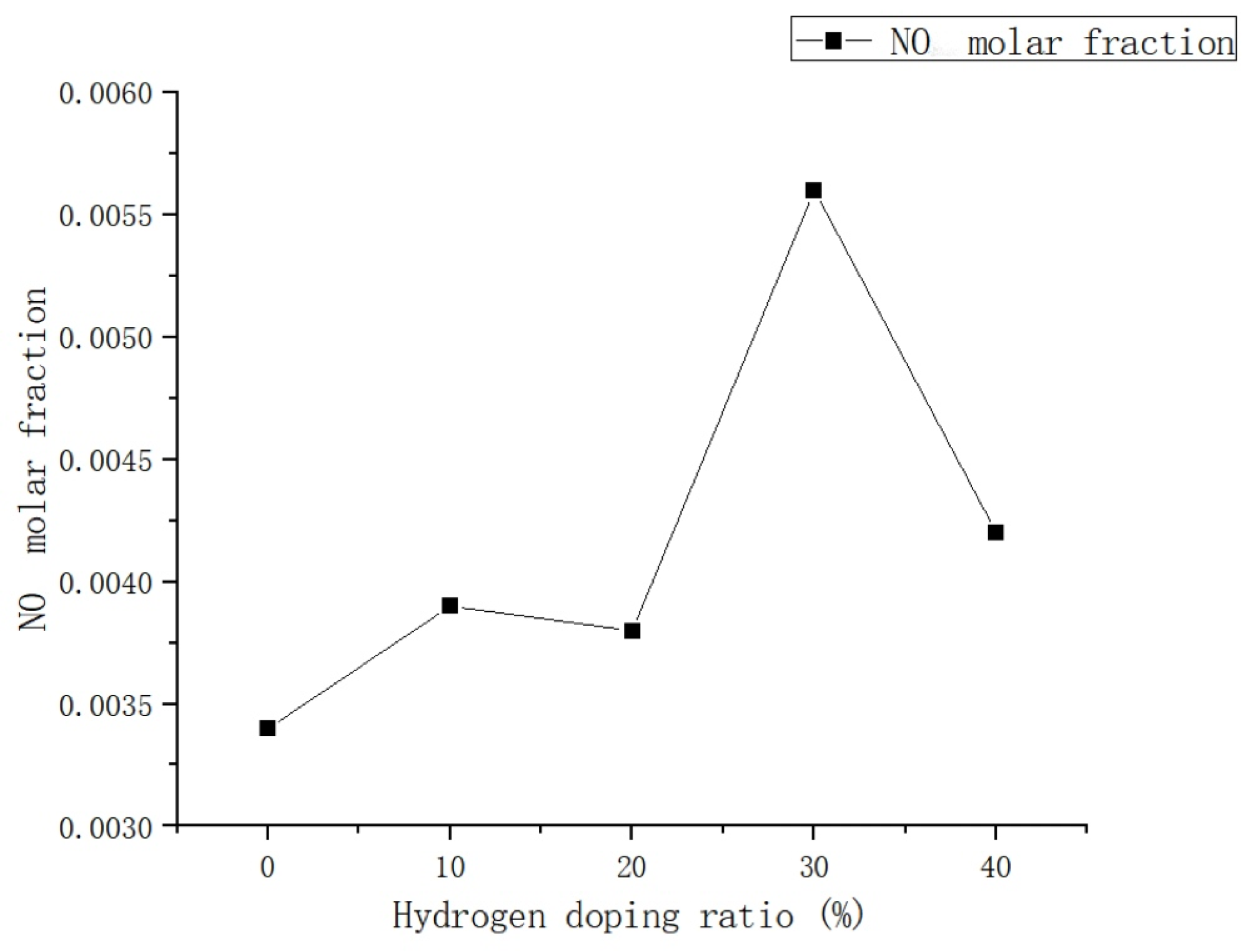
Due to the relatively uniform distribution of temperature in the rear section of the combustion chamber, the production of NO is comparatively low. As illustrated in Figure 12, the addition of hydrogen has minimal impact on NO emissions within a 0–20% hydrogen blending ratio, which is consistent with the findings of Xie et al. [23]. Regarding the compatibility of residential gas water heaters with natural gas–hydrogen blends, it has been observed that when the hydrogen doping ratio is less than 0.3, there is a slight increase in the molar fraction of NO with an increase in H2, but this increase is relatively small. However, when the hydrogen doping ratio exceeds 30%, there is a significant rise in NO emissions, primarily attributed to the increase in thermal NO. This phenomenon suggests that the addition of H2 enhances the formation of NO in the combustion process, particularly at the inlet of the combustion chamber. The introduction of H2 increases the generation of OH radicals, thereby promoting the N + OH <=> NO + H chain reaction, which is a primary pathway for NO formation. Therefore, the introduction of H2 results in an increase in NO emission concentration. However, when the hydrogen ratio is further increased to 40%, there is a significant reduction in NO emissions. This can be attributed to the minimal amount of air required for H2 combustion, leading to a decrease in pollutant emissions as the hydrogen blending ratio increases. Nevertheless, further analysis and research are necessary to determine the specific impact of H2 on NO emissions [24].
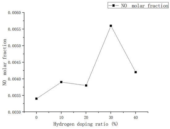
Figure 12.
Influence of hydrogen doping volume fraction on NO levels in the combustion zone.
From the overall trend, it is evident that the addition of hydrogen has a significant impact on the production of NO. Specifically, when 10% volume of H2 is added, there is a 14.7% increase in NO emissions compared to pure methane combustion. When the hydrogen doping ratio is increased to 20%, the NO emission is reduced by 2.5% compared to a 10% hydrogen doping ratio. However, with a further increase in the hydrogen doping ratio to 30%, the NO emission increases by 47.3% compared to a 20% hydrogen doping ratio. When the hydrogen doping ratio reaches 40%, the NO emission is observed to be 25% lower compared to when the hydrogen doping ratio is at 30%. This finding suggests that the rate of NO emission experiences its most significant increase as the hydrogen ratio increases from 20% to 30%. It is important to note that, although there was a relatively small increase in NO emissions when the hydrogen blending ratio reached 20%, it increased at a faster rate as the hydrogen ratio increased from 20% to 30%. However, when the hydrogen proportion exceeded 20%, there was a significant increase in NO emissions.
Based on the analysis above, it is recommended to maintain the proportion of hydrogen within 20% when adding hydrogen to natural gas in water heaters. This is crucial for achieving a balance between combustion efficiency and environmental impact, particularly the key indicator of NO emission.
Based on the analysis above, it is recommended to maintain the proportion of hydrogen within 20% when adding hydrogen to natural gas in water heaters. This is crucial for achieving a balance between combustion efficiency and environmental impact, particularly the key indicator of NO emission. However, it is crucial to ensure that the combustion temperature of the gas water heater does not become excessively high, as this can hurt its normal operation. To control NO emissions and ensure the normal operation of the water heater when natural gas is blended with hydrogen, optimization should be focused on two main aspects. Firstly, it is important to maintain a moderate combustion temperature, particularly the peak temperature during the combustion process. Secondly, ensuring a uniform distribution of the temperature field can help reduce incomplete combustion and subsequently decrease the generation of NO. Based on the above analysis, it is evident that a 20% hydrogen blending ratio has a relatively minimal impact on nitrogen oxide emissions in natural gas–hydrogen blending combustion in gas water heaters.
Currently, there are numerous specific strategies and technologies available to reduce NO emissions. These include both technical and policy measures. Technical measures primarily encompass clean combustion, combustion control technology, and post-combustion control technology. Combustion control technology encompasses combustion, burning, and flue gas recirculation technologies. In terms of post-combustion control technologies, the main methods include selective catalytic reduction (SCR), selective non-catalytic reduction (SNCR), and SCR-SNCR hybrid technology. The policy measures primarily involve the enhancement of NO emission standards, the reinforcement of intelligent monitoring and supervision for emissions, and the implementation of new energy-related technologies. For gas water heater manufacturers and consumers, it is important to properly install and use gas water heaters to control and reduce the generation of NO. Based on the findings of this study, the following points are recommended for users:
- (1)
- In the process of using gas water heaters, it is advisable to minimize the number of switches.
- (2)
- During the installation process of a gas water heater, it is crucial to ensure that the air inlet remains unobstructed and that there is sufficient air intake. This is essential for the proper functioning and safety of the water heater.
- (3)
- Timely maintenance of the components of a gas water heater is crucial.
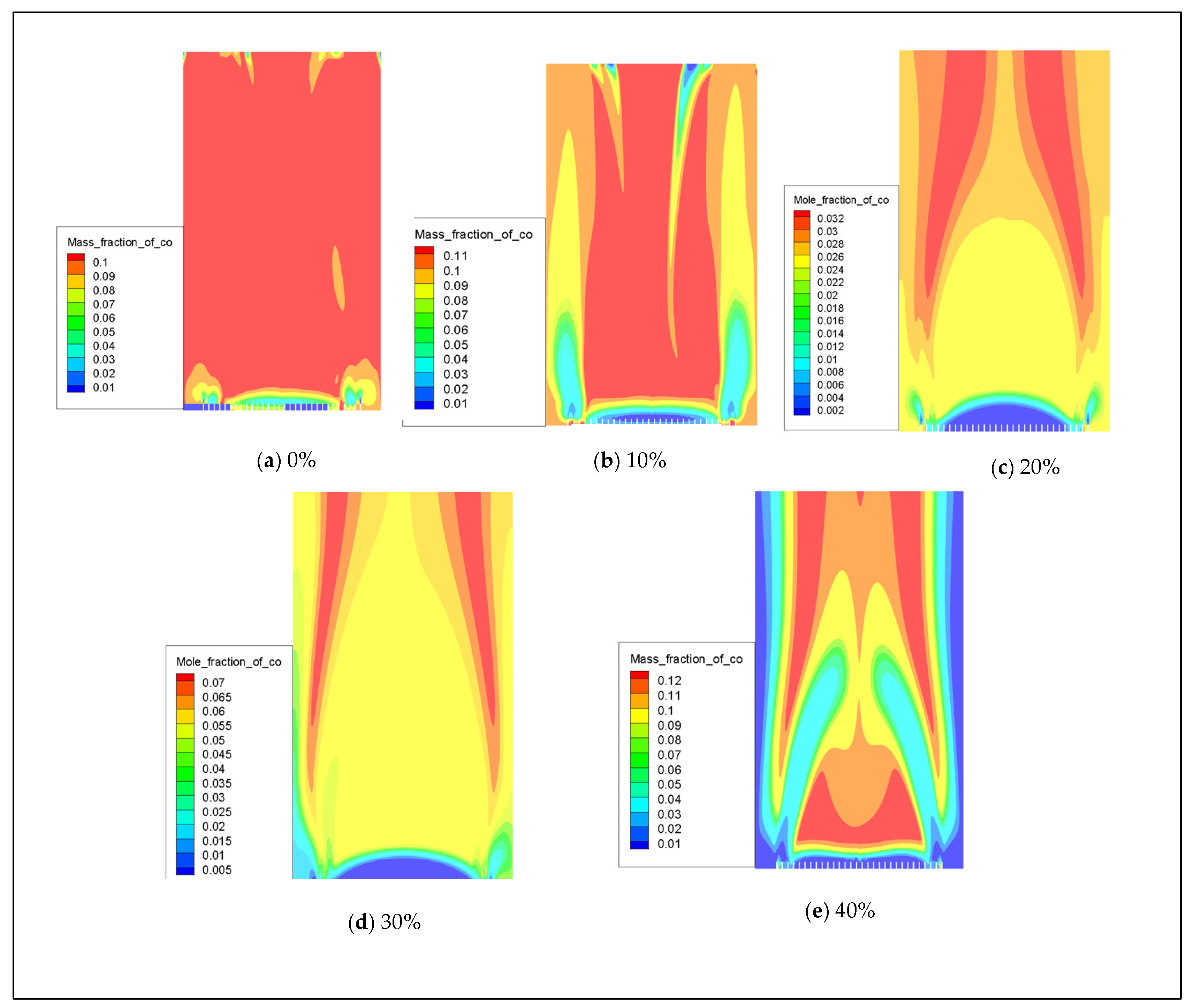
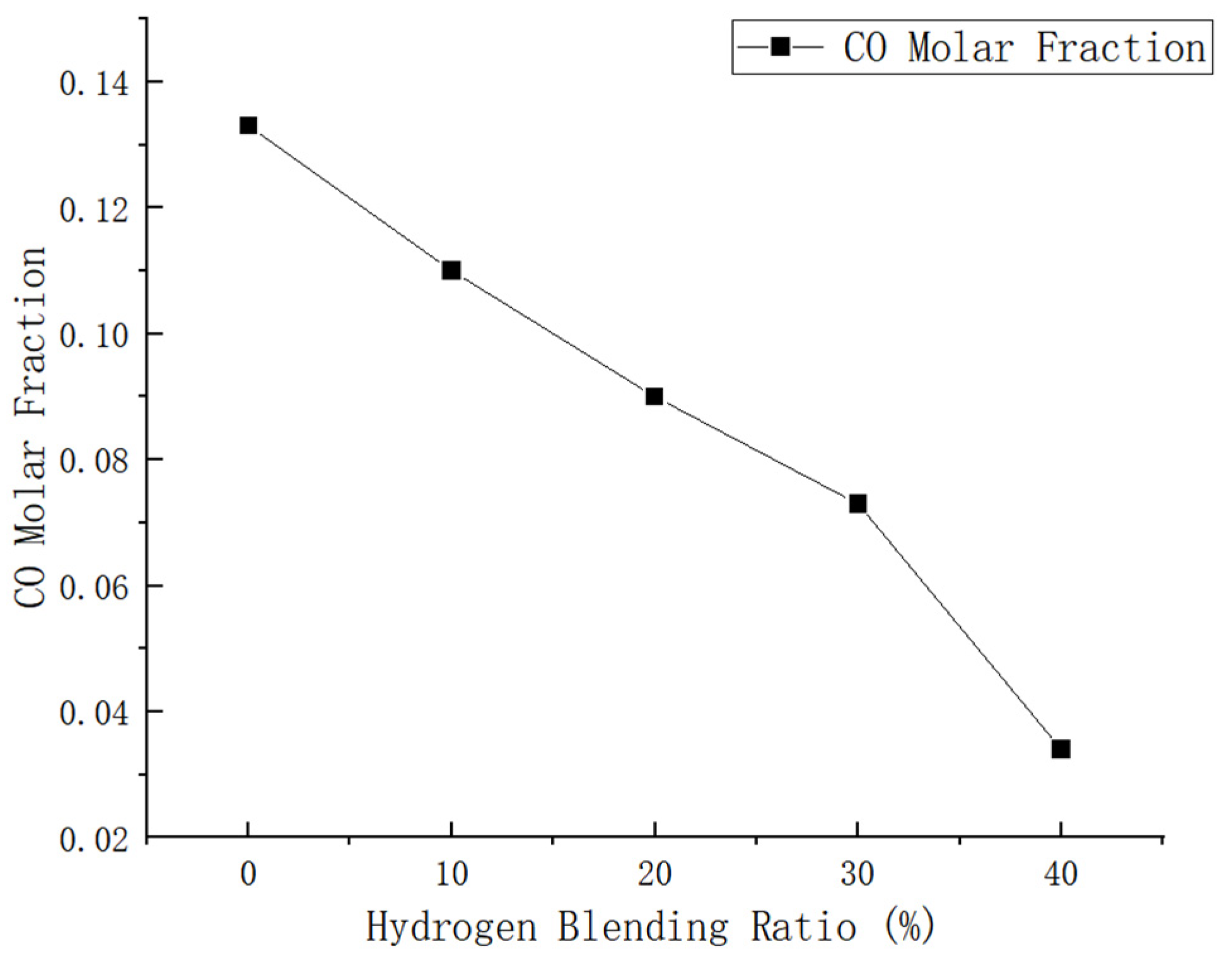
In the event of insufficient oxygen supply or ineffective smoke exhaust, gas water heaters may undergo incomplete combustion, leading to the generation of carbon monoxide (CO). When the concentration of CO exceeds 400 ppm [25], it can result in symptoms of poisoning. Therefore, it is crucial to simulate the formation of CO following the combustion of hydrogen-doped natural gas to ensure that CO emissions remain within safety standards and prioritize user safety [18]. This simulation experiment is designed with five sets of conditions to maintain a constant rated power. The data from the simulation experiments include hydrogen doping ratios of 0%, 10%, 20%, 30%, and 40%. The distribution of CO produced by combustion with varying hydrogen volume fractions is illustrated in Figure 13. Figure 14 demonstrates that incorporating hydrogen leads to a significant reduction in CO emissions from the water heater. This effect becomes particularly pronounced after introducing 20% hydrogen, resulting in a substantial decrease in CO emissions.
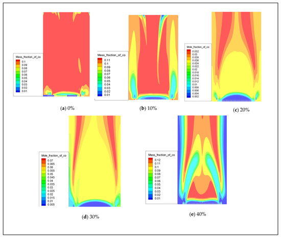
Figure 13.
The influence of hydrogen volume fraction on the overall distribution of CO.
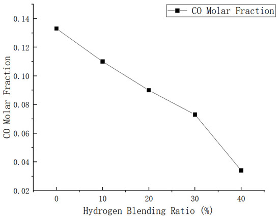
Figure 14.
Influence of hydrogen doping volume fraction on carbon monoxide in the combustion zone.
The maximum mole fractions of CO in the combustion chamber are 0.133, 0.110, 0.090, 0.073, and 0.034 at H2 volume fractions of 0–40%, respectively.
After conducting calculations, it was determined that the addition of 10% H2 to methane can result in a 4.1% reduction in CO emissions compared to pure methane combustion. Furthermore, the inclusion of 20% H2 led to a significant decrease of 32.3% in CO emissions when compared to natural gas. When 30% H2 was added, there was a decrease in CO emissions by 45.1%. Additionally, the addition of 40% H2 resulted in a remarkable reduction of 74.4% in CO emission compared to pure methane combustion.
The comprehensive analysis indicates that as the hydrogen blending ratio increases, there is a significant reduction in CO emissions.
The simulation results are consistent with the research conducted by Chen Haojie et al. [26], indicating that the presence of hydrogen in the mixed gas can effectively reduce CO emissions.
It is worth noting that the formation of CO is closely associated with the temperature of the combustion reaction. As the volume fraction of hydrogen increases, so does the combustion temperature, leading to a corresponding decrease in the molar fraction of CO [27].
With the increase in the volume ratio of hydrogen, the mole fraction of free radicals O and OH in the chemical reaction of natural gas mixed fuel also increases. The formation of CO can be expressed by the following formula:
where R represents the hydrocarbon atom group. According to Bowman’s study on the formation mechanism of CO, it has been determined that the formation of CO can also be represented by the following reaction model:
RH→RCHO→RCO→CO
Based on the following mechanism, an increase in the hydrogen ratio and OH mole fraction can result in a higher consumption of CO.
Another crucial factor to consider is that the formation of CO results from the incomplete combustion of carbon [28]. Due to hydrogen’s lower ignition point compared to methane, it will preferentially react with methane, leading to a more intense reaction. The combustion of hydrogen releases heat, which, in turn, increases the reaction temperature of methane. This promotes the complete combustion of methane and reduces the generation of CO. Therefore, integrating hydrogen can effectively decrease the production of CO.
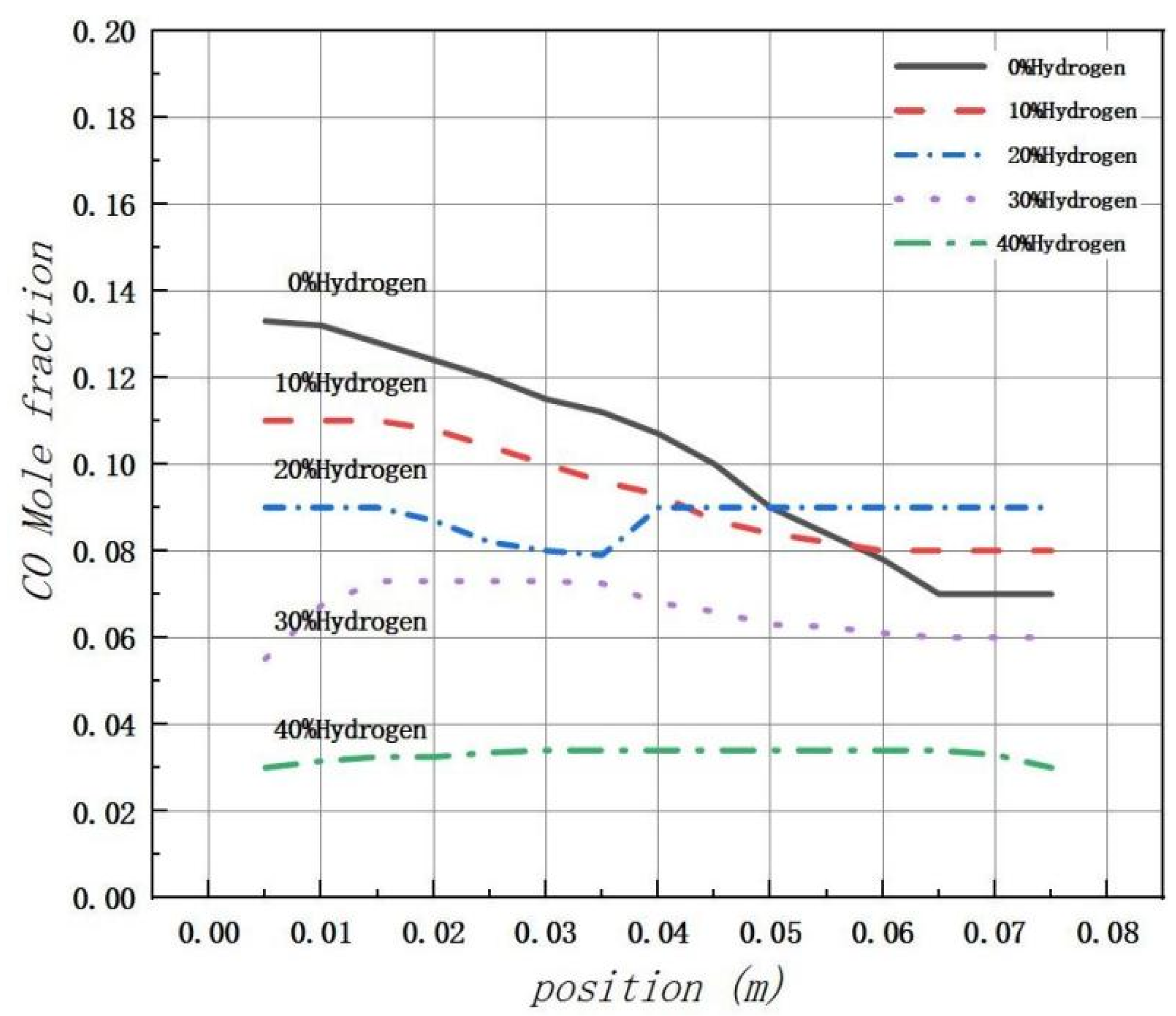
Figure 15 illustrates that the peak production of CO is primarily concentrated near the inlet of the combustion chamber. However, due to the low initial reaction temperature, many carbon elements are not fully combusted, resulting in a peak in CO levels at the inlet. The introduction of hydrogen significantly increases the concentration of free radicals, such as H, O, and OH, in the combustion chamber. This promotes the combustion reaction and thus inhibits the formation of CO. Regardless of the volume fraction conditions of H2, most generated CO is found to be concentrated at the fuel inlet with a slight decrease to a stable level thereafter.
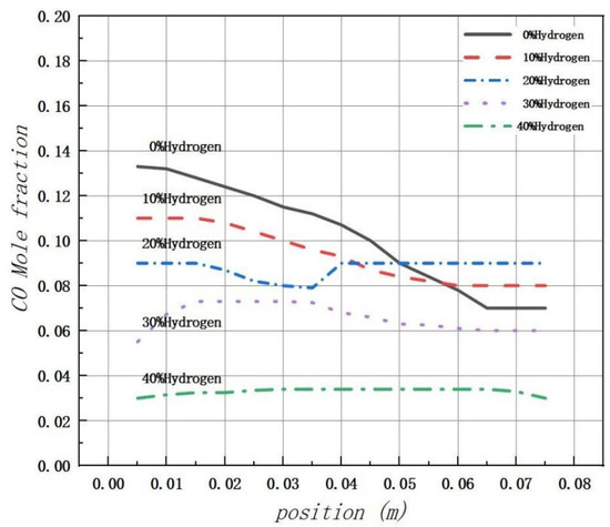
Figure 15.
The mole fraction distribution of carbon monoxide (CO) in the combustion chamber is analyzed under varying amounts of hydrogen.
The distribution of CO products throughout the entire combustion region was analyzed using Fluent 19.2 software. The findings indicate that a significant reduction in CO mole fraction and relatively stable combustion temperature in the combustion chamber occur when the hydrogen blending ratio reaches 20%. Therefore, a hydrogen blending ratio of 20% is considered most favorable for hydrogen blending combustion of natural gas in gas water heaters.
Due to the high reactivity of hydrogen, it has the potential to cause material degradation and safety issues. The blending of hydrogen not only affects combustion performance but also has the potential to impact the service life of gas water heaters. Material failure due to the presence of hydrogen or its reaction with metal includes hydrogen damage, high-temperature hydrogen and hydrogen sulfide corrosion, wet hydrogen sulfide corrosion, and so on. Since most household appliances in terminal applications contain metal, the presence of hydrogen in the metal material or its reaction with some components can reduce the toughness and plasticity of the metal material, leading to cracking, lag fracture, and brittle fracture. This ultimately results in a shortened lifespan for household appliances and decreased safety performance. Currently, there is a lack of national industry standards for natural gas hydrogen-doped gas appliances and natural gas hydrogen-doped gas. Additionally, the performance evaluation of these appliances is insufficient. Some experts have proposed the use of a combination of natural gas and renewable fuels with burner heads for mixed fuels to address the impact of hydrogen doping on household appliance performance [29]. However, achieving this goal is proving to be quite challenging. Therefore, it is still necessary to address this issue by considering the hydrogen doping ratio. Based on theoretical research, various organizations have conducted a series of experiments testing the combustion of hydrogen-doped natural gas at civil gas terminals, including gas stoves and water heaters. The experimental results demonstrate the feasibility of incorporating 20% hydrogen into the measured civil gas terminal with minimal impact on its application. In addition, experiments have been conducted to evaluate the impact of the hydrogen blending ratio on the performance of household appliances. The experimental findings indicate that there is no gas leakage in any part of the natural gas hydrogen-doped fuel before reaching the burner fire hole at the gas inlet of the water heater, demonstrating good air tightness throughout the gas path. Simultaneously, the combustion conditions, heat load, and hot water performance of the gas water heater were assessed. The comprehensive test concludes that it is feasible to use 20% hydrogen-doped natural gas in the civil gas terminal tested in the experiment.
4. Conclusions
Based on the Gri-mech3.0 combustion mechanism, the FGM method was employed to simulate the combustion process of hydrogen-doped natural gas in a gas water heater. By monitoring changes in combustion chamber temperature, NOx, and CO content and analyzing the impact of hydrogen doping on combustion, the following conclusions can be drawn:
- (1)
- Simulation results indicate that the temperature in the combustion chamber becomes more concentrated as the hydrogen doping ratio increases. Specifically, the high-temperature range is most concentrated when the hydrogen doping ratio is between 10 and 40%. Furthermore, as the hydrogen doping ratio increases, the temperature distribution in the combustion chamber becomes more uniform. The addition of hydrogen leads to rapid combustion, resulting in a concentration of high temperatures mainly at the inlet of the combustion chamber. This phenomenon may accelerate the aging of gas appliances.
- (2)
- Through simulating and observing the changes in NOx levels within the combustion chamber, it was determined that the introduction of methane mixed with hydrogen leads to a slight increase in NOx emissions. This increase is attributed to the rise in temperature within the combustion chamber resulting from the addition of hydrogen. It was observed that when the blending ratio of hydrogen is below 20%, there is an increase in NOx emissions, albeit at a minimal level. Furthermore, combustion efficiency increased by 11.7% compared to using pure natural gas. Therefore, it can be concluded that a hydrogen blending ratio of 20% is optimal for this process.
- (3)
- The impact of reducing CO emissions is most noticeable following natural gas blending. The reduction in CO levels will decrease by 10–20% for every 10% increase in H2 at hydrogen blending ratios ranging from 0 to 40%, with the most significant reduction occurring at a hydrogen blending ratio of 20%. This can be attributed to two factors. Firstly, the generation of CO is a result of the incomplete combustion of carbon, and the inclusion of H2 can effectively reduce its production. Secondly, the combustion temperature rises as the hydrogen doping ratio increases, leading to a more complete combustion process and further reduction in CO levels.
Author Contributions
Conceptualization, S.L. and X.L.; Methodology, S.L.; Software, S.L. and X.L.; Validation, S.L. and X.L.; Resources, H.J. and Y.L.; Writing—original draft, S.L.; Supervision, Y.W. All authors have read and agreed to the published version of the manuscript.
Funding
This research received no external funding.
Data Availability Statement
The original contributions presented in the study are included in the article, further inquiries can be directed to the corresponding author.
Conflicts of Interest
The authors declare no conflict of interest.
References
- Jia, B.; Xian, C.; Tsau, J.-S.; Zuo, X.; Jia, W. Status and outlook of oil field chemistry-assisted analysis during the energy transition period. Energy Fuels 2022, 36, 12917–12945. [Google Scholar] [CrossRef]
- Wang, Y.; Zhang, X.; Li, Y. Numerical simulation of methane-hydrogen-air premixed combustion in turbulence. Int. J. Hydrogen Energy 2023, 48, 7122–7133. [Google Scholar] [CrossRef]
- Leicher, J.; Schaffert, J.; Carpentier, S.; Albus, R.; Görner, K. Impact of Hydrogen Admixture on Combustion Processes–Part I: Theory; ThyGa: Saint-Denis, France, 2020. [Google Scholar]
- Choudhury, S.; McDonell, V.G.; Samuelsen, S. Combustion performance of low-NOx and conventional storage water heaters operated on hydrogen-enriched natural gas. Int. J. Hydrogen Energy 2020, 45, 2405–2417. [Google Scholar] [CrossRef]
- Zhao, Y.; Hickey, B.; Srivastava, S.; Smirnov, V.; McDonell, V. Decarbonized combustion performance of a radiant mesh burner operating on pipeline natural gas mixed with hydrogen. Int. J. Hydrogen Energy 2022, 47, 18551–18565. [Google Scholar] [CrossRef]
- Lin, J.; Li, H.; Zhang, Y.; Yang, J. Experimental and Numerical Study of a Two-Stage Swirl Burner. Energies 2022, 15, 1097. [Google Scholar] [CrossRef]
- Xin, Y.; Wang, K.; Zhang, Y.; Zeng, F.; He, X.; Takyi, S.A.; Tontiwachwuthikul, P. Numerical simulation of combustion of natural gas mixed with hydrogen in gas boilers. Energies 2021, 14, 6883. [Google Scholar] [CrossRef]
- Wang, J.; Huang, Z.; Tang, C.; Zheng, J. Effect of hydrogen addition on early flame growth of lean-burn natural gas–air mixtures. Int. J. Hydrogen Energy 2010, 35, 7246–7252. [Google Scholar] [CrossRef]
- Du, W.; Zhou, S.; Qiu, H.; Zhao, J.; Fan, Y. Experiment and numerical study of the combustion behavior of hydrogen-blended natural gas in swirl burners. Case Stud. Therm. Eng. 2022, 39, 102468. [Google Scholar] [CrossRef]
- Wang, K.; Li, F.; Zhou, T.; Ao, Y. Numerical Study of Combustion and Emission Characteristics for Hydrogen Mixed Fuel in the Methane-Fueled Gas Turbine Combustor. Aerospace 2023, 10, 72. [Google Scholar] [CrossRef]
- Ren, F.; Chu, H.; Xiang, L.; Han, W.; Gu, M. Effect of hydrogen addition on the laminar premixed combustion characteristics of the main components of natural gas. J. Energy Inst. 2019, 92, 1178–1190. [Google Scholar] [CrossRef]
- Yan, R.S.; Gao, W.; Zhang, Y.; Zhang, J. Combustion performance testing of hydrogen-containing natural gas on household natural gas appliances. Nat. Gas Ind. 2018, 38. [Google Scholar]
- Zhu, R. Numerical Simulation and Experimental Study of Hydrogen Blending Combustion Characteristics in a Swirl Gas Stove. Master’s Thesis, Guangdong University of Technology, Guangzhou, China, 2022. [Google Scholar]
- Wu, C. Feasibility Study on the Use of Natural Gas Mixed with Hydrogen. Ph.D. Thesis, Chongqing University, Chongqing, China, 2018. [Google Scholar]
- Leicher, J.; Schaffert, J.; Cigarida, H.; Tali, E.; Burmeister, F.; Giese, A.; Albus, R.; Görner, K.; Carpentier, S.; Milin, P.; et al. The impact of hydrogen admixture into natural gas on residential and commercial gas appliances. Energies 2022, 15, 777. [Google Scholar] [CrossRef]
- de Vries, H.; Mokhov, A.V.; Levinsky, H.B. The impact of natural gas/hydrogen mixtures on the performance of end-use equipment: Interchangeability analysis for domestic appliances. Appl. Energy 2017, 208, 1007–1019. [Google Scholar] [CrossRef]
- Li, H.M. Numerical Simulation and Experimental Study on Combustion Performance of Partially Premixed Gas Water Heaters. Master’s Thesis, Tianjin University, Tianjin, China, 2017. [Google Scholar]
- Zhang, W.; Wang, J.; Hu, G.; Li, D.; Wang, Z.; Huang, Z. Simulation of intermediate components in partially premixed turbulent combustion based on LES-FGM method. J. Appl. Math. Mech. 2019, 44, 1031–1041. [Google Scholar]
- Li, Y.; Shen, J. Numerical simulation of combustion characteristics of hydrogen-doped natural gas HCCI engine. J. Automot. Eng. 2019, 9, 182–192. [Google Scholar]
- Yang, J. Research and Application of FGM Premixed and Partially Premixed Turbulent Combustion Models; Graduate School of the Academy of Sciences (Institute of Engineering Thermophilic): Beijing, China, 2012. [Google Scholar]
- Zhan, X.; Chen, Z.; Qin, C. Effect of hydrogen-blended natural gas on combustion stability and emission of water heater burner. Case Stud. Therm. Eng. 2022, 37, 102246. [Google Scholar] [CrossRef]
- An, E.; Zhang, R.; Han, Y.; Liu, D. Grid-independent analysis for numerical simulation of multiphase turbulent combustion. Boil. Technol. 2018, 49, 54–58. [Google Scholar]
- Zhang, L.; Zhang, F.; Zhao, Q.; Shan, G.; Bockhorn, H. Based on Turbulent Flame Velocity Closure and Beta-PDF Partial Premixed Combustion Model; Chinese Society of Engineering Thermophilic: Beijing, China, 2014. [Google Scholar]
- Xie, Y.; Qin, C.-k.; Huang, X.-Q. Study on adaptability of domestic gas water heater to hydrogen-doped natural gas. City Gas 2021, 1–5. [Google Scholar]
- Fan, R.; Zhang, T.; Li, J.; Yan, Y. Large eddy simulation of coaxial jet non-premixed flame based on FGM model. Therm. Power Eng. 2023, 38, 42–49. [Google Scholar] [CrossRef]
- Basinger, E.; Hickey, B.; McDonell, V. A compilation of operability and emissions performance of residential water heaters operated on blends of natural gas and hydrogen including consideration for reporting bases. Int. J. Hydrogen Energy 2023, 48, 19733–19749. [Google Scholar] [CrossRef]
- Chen, H. Experimental Study on the Influence of Hydrogen Content in Natural Gas on Combustion Equipment. Master’s Thesis, Beijing University of Civil Engineering and Architecture, Beijing, China, 2017. [Google Scholar]
- Liu, Q. Simulation of Structure and Working Conditions of Low Knoxx Emission of Natural Gas Burner. Master’s Thesis, Shanghai Dianji University, Shanghai, China, 2023. [Google Scholar] [CrossRef]
- Hsu, P.-C.; Lin, T.-H.; Su, H.-M.; Lee, H.-C.; Huang, C.-H.; Lai, W.-T.; Sheu, S.-H. Acute carbon monoxide poisoning resulting in ST elevation myocardial infarction: A rare case report. Kaohsiung J. Med. Sci. 2010, 26, 271–275. [Google Scholar] [CrossRef] [PubMed]
Disclaimer/Publisher’s Note: The statements, opinions and data contained in all publications are solely those of the individual author(s) and contributor(s) and not of MDPI and/or the editor(s). MDPI and/or the editor(s) disclaim responsibility for any injury to people or property resulting from any ideas, methods, instructions or products referred to in the content. |
© 2024 by the authors. Licensee MDPI, Basel, Switzerland. This article is an open access article distributed under the terms and conditions of the Creative Commons Attribution (CC BY) license (https://creativecommons.org/licenses/by/4.0/).

