Article

Insights on Blackstart Provisioning Using a Synchronous Generator and Grid-Forming Inverter Using EMT Simulations

1
Klipsch School of Electrical and Computer Engineering, New Mexico State University, Las Cruces, NM 88003, USA
2
Electric Power Research Institute, Palo Alto, CA 94304, USA
3
Florida Power and Light Company (FPL), Miami, FL 33141, USA
*
Author to whom correspondence should be addressed.
Deceased author.
Energies 2024, 17(16), 4067; https://doi.org/10.3390/en17164067
Submission received: 17 June 2024 / Revised: 11 August 2024 / Accepted: 12 August 2024 / Published: 16 August 2024
(This article belongs to the Special Issue Grid-Forming Converters in Future Power Grids)

Abstract

:
Grid-forming inverters (GFMIs) have been identified as critical assets in ensuring modern power system reliability. Their ability to synthesize an internal voltage reference while emulating synthetic inertia has sparked extensive research. These characteristics have recently piqued interest in their capacity to provide blackstart ancillary services. The blackstart of a bulk power system poses significant challenges, namely the large transients from the energization of unloaded transformers, rotational motor loads, and long transmission cables, which have been effectively studied using conventional synchronous generators (SGs). The concept of an inverter-based resource (IBR)-based blackstart continues to be an open research area necessitating further investigations due to the known limitations of IBRs such as low short-circuit current capabilities. This paper presents a blackstart case study of a bulk power system investigating the performances of a conventional SG to a GFMI when utilizing hard switching methods. The paper qualitatively investigates the transient inrush currents from the transformer and rotational load energization sequences. Additional examinations into the significance of the GFMI’s current-limiting schemes and voltage control loop compensator gains are presented. Furthermore, the harmonic distortions from the transformer energization sequence are also evaluated. Finally, a full network energization case is presented to demonstrate how both sources can provide blackstart provisioning services. The models are developed in EMTDC/PSCAD using real-world transmission planning data.

1. Introduction

The use of inverter-based resources (IBRs) is significantly increasing, intending to meet renewable integration and decarbonization targets within the bulk power grid. Currently deployed grid-tied inverters are designed to follow the grid and are thus known as grid-following inverters (GFLI) [1]. With the use of a phase-locked loop (PLL) controller to synchronize with the grid, the GFLI can track the grid voltage; thus, they can be categorized as current controlling sources [2]. In contrast, grid-forming inverters (GFMIs) can synthesize an internal voltage phasor reference; therefore, they can be categorized as voltage sources similar to synchronous generators (SGs). The abilities of GFMIs to emulate SGs have sparked significant interest in the industry. One particular area of interest is their abilities in providing blackstart ancillary services. The blackstart process establishes an electrical path known as the cranking path, using a designated source known as the blackstart generator, to restart the power plant auxiliary loads as illustrated in Figure 1. The importance of blackstart provisioning and the closely related but more comprehensive problem of bulk transmission system restoration were the subject of significant research in the late 1990s. The IEEE Power Systems Restoration Group prepared several key publications that describe issues, solutions, and best practices [3]. Lately, with the introduction of GFMIs, the blackstart process has revived interest in the use of a GFMI. Due to the unique challenges presented during the blackstart process, such as energizing unloaded transformers that are larger than the blackstart resource capacities, as well as energizing rotating loads, which are known to produce uncontrolled fast transients, additional research is necessitated, since power inverters have limited capabilities such as generating inertia and short-circuit currents. The community interest in this topic is evidenced by the extensive efforts of industry and research institutions in developing appropriate GFMI models and defining the GFMI requirements in this regard. Research institutions such as the Electric Power Research Institute (EPRI) [4,5,6] and the National Renewable Laboratories (NREL) [7] have begun initiatives into the development and simulation of GFMI models that also include the exploration of GFMI capabilities in performing a blackstart. Furthermore, the North American Electrical Reliability Corporation (NERC) mandates a restoration compliance to all transmission owners. The Emergency and Operational planning (EOP-005-R5), in particular, necessitates transmission planning to assess the viability of the blackstart restoration strategy using simulation-based studies; therefore, further evaluation studies investigating blackstart using IBRs are necessary to ensure their feasibility in restoration and overcoming the complex energization transients.
The ability of an IBR-based blackstart using GFMIs in this regard has been studied in [8]. Modifications to the GFM virtual synchronous machine (VSM) outer loop controls are proposed to improve island synchronization and voltage support during a blackstart, and the simulations are validated using power hardware in the loop (PHIL) tests. In [9,10], the feasibility of deploying off-shore wind farm-based, multi-modular high-voltage direct current (HVDC) converters (MMCs) for a blackstart application is studied. The transformer inrush current issue was addressed by comparing a ramping voltage method, also known as soft energization (SE), to the conventional hard-switching method. The presented analysis neglects transformer magnetizing characteristics in the simulation models. In [11,12], classical transformer inrush current mitigation strategies are investigated using a GFMI resource. The studies investigate point-of-wave switching (POW), the use of pre-insertion resistors (PIRs) in circuit breakers, and the soft energization (SE) method. The results demonstrated that the SE method, which controls the system voltage using a ramp applied at the inverter’s voltage controller, is the most effective method for minimizing inrush currents. It should also be noted that employing the SE method requires the circuit breakers that make up the cranking path to be in a closed state; therefore, all transformer assets on the cranking path are energized at the same time. Furthermore, the studies neglect detailed medium-voltage (MV) transformers that are coupled with inverters, and the analysis is performed using a single loop voltage controller in the GFMI model without any current-limiting schemes. In [13], blackstarting using a GFMI is explored, and the SE method is evaluated against a current-limiting scheme, which serves as a reference modifier; however, the transformer magnetizing models such as transformer residual flux have not been accounted for.
The objective of this paper is to expand the understanding of an IBR-based blackstart by presenting further comprehensive investigations that assess the abilities of GFMIs in this setting. We focus namely on the transformer and synchronous motor energization (that represents rotational load at the off-site power plant) followed by a full cranking path energization study. The results of using the GFMI are evaluated against the conventional blackstart results based on using the SG to demonstrate the performance of the GFMIs. The contributions of this paper can be summarized as follows:
  • A detailed study comparison between a GFMI and a conventional SG during a blackstart: Transformer and rotational motor load energization sequences were evaluated in detail; as a result, the findings reveal differences between the GFMI and SG. Nonetheless, the studies demonstrate that the GFMI can blackstart a bulk power system using conventional hard energization switching methods. (Section 3 and Section 4).
  • Evaluation of the current-limiting schemes: These schemes are employed to protect the power inverter from the large inrush currents during the transformer and rotational motor load energization sequences. Furthermore, our investigations revealed that this current-limiting scheme behaves similarly to the SE method, which is executed by modifying the references of the GFMI. (Section 3).
  • Investigation of voltage and current harmonic distortions: The results demonstrated that the sympathetic interaction between the inverter’s medium voltage (MV) and plant step-up transformer generates extended inrush currents and over-voltages, resulting in higher harmonic distortions, which may require the protection relays to be adjusted. (Section 3).
  • Proposing an alternative method of restoring frequency after load pick-up by integrating a closed-loop controller in a power plant controller module (PPC). This method is beneficial, since it eliminates inverter-level control modifications. Communication delays between the PPC and inverter are also considered. (Section 4).

2. Blackstarting Concepts

2.1. Blackstart Synchronous Generator

Blackstart generators are specially designated to be used for the cranking path energization and also assist in load pick-up during system restoration. Currently, these are synchronous machine generators with gas turbine, hydroelectric, or diesel units [14]. It is critical to monitor the blackstart generator closely, as restoration cannot start until the blackstart unit can successfully provide cranking power to a larger off-site generator. The blackstart generator must be able to maintain the voltage and reactive power as well as maintain the frequency in the system during this time [15]. A governor maintains the speed of the machine as the load changes by adjusting the prime mover inputs to increase or decrease the power outputs based on frequency changes in the system. During normal operation, the generators are in droop control; however, during the blackstarting process, the blackstart generator must be on isochronous control to maintain nominal system frequency. In this paper, the SG model uses the PSCAD synchronous machine model as the generator model [14], the governor was modeled using the IEEE GGOV1 model, and an exciter model was also added using the AC8B model. Details of the SG model are provided in Table 1.

2.2. Transformer Energization Sequence

When a transformer is energized in an uncontrolled manner, it can manifest a large magnetizing inrush current in order to satisfy the transformer flux requirements within the core. The magnetizing inrush current will be determined by the characteristics of the transformer’s non-linear saturation curve, the residual flux, the impedance between the transformer and the voltage source, and finally the closing angle of the voltage waveform. When the core flux exceeds a linear zone, the magnetizing current grows at a faster rate, despite small flux increments. The transformers in this paper were modeled using the PSCAD’s master library transformer models. To avoid inconsistencies, all the transformers in the PSCAD model were modeled using the same magnetizing characteristics such as hysteresis curves and voltage knee curves. Further details on the model data can be found in Table 1; additionally, for further reference, details on the PSCAD transformer models can be found in [16].

2.3. Grid-Forming Inverter Model

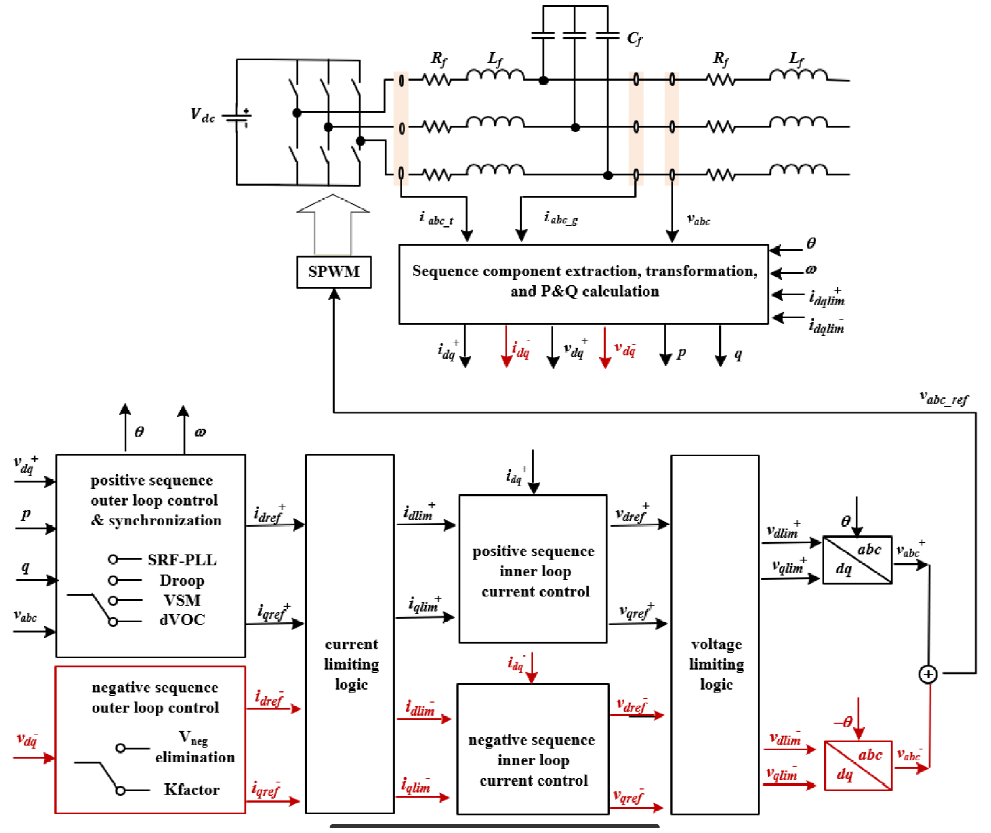
The baseline grid-forming inverter (GFMI) model for this study was developed by the Electric Power Research Institute (EPRI). The model is based on a multi-loop design that supports both positive and negative sequence control (each sequence has its own control loop), which is important for managing unbalanced power system conditions [17]. Furthermore, positive and negative sequence control is a requirement of many interconnection standards, including IEEE 2800 [18], which requires IBRs to contribute to negative sequence currents under unbalanced disturbances. Figure 2 illustrates the overall GFMI architecture, which, contains a constant DC source. The sequence component extraction block contains the transformations of the inductor current and capacitor voltage measurements from abc-frame to dq-frame, which are then used in subsequent control schemes. The outer loop controller block is responsible for power and voltage regulation as well as synchronization of the GFMI with the electric grid. The model in particular comprises four industry-standard GFM outer loop control strategies: virtual synchronous machine (VSM), synchronous-reference frame-phase locked loop (SRF-PLL), droop and dispatchable virtual oscillator control (dVOC). The VSM control strategy in particular emulates the classical generator swing equation using inertia and the damping factor to derive the frequency and VSM phase angle references, which are used to control active power exchange with the grid similarly to an SG. The voltage references are generated by the Q-V droop loop, which are assigned as voltage references used by the inner control loops for voltage control and reactive power exchange with the grid. Due to its ability to emulate an SG, the VSM control strategy was the preferred grid-forming control used for the analysis presented in this paper. For a deeper theoretical understanding of the various GFMI control strategies, please refer to [4,5]. Furthermore, references [19,20] also provide comparisons between various GFM controllers during a blackstart.
The inner control loops are based on the cascade control loop architecture with a voltage loop separating the inner current loop. A current-limiting scheme is implemented between these control loops, allowing current references to be modified per the current-limiting scheme logic when the currents generated by the voltage loop exceed the current limit established. Further details on the current-limiting scheme are presented in subsequent sections. The results of the control loops are then passed onto the voltage modulation scheme for voltage control. For these studies, an averaged model has been substituted from the conventional switching model, which eliminates the need for a pulse-width-modulation (PWM) scheme.

3. Comparative Network Case Studies

3.1. Study Assumptions and Methods

In this section, the transformer energization and motor starting analysis are compared using an SG and the GFMI. Additional sensitivity studies investigating the current-limiting scheme and impact of the voltage controller compensator gains are also presented based on the transformer energization sequence. The simulation case is initialized with the electrical system in a de-energized state with all circuit breakers in the open position. The circuit breaker closing times for the transformer energization assessments in particular were also studied, and the results presented in this paper are based on phase C voltage waveform closing at 0 for the maximum inrush current in phase C. The simulation studies were carried out in the EMT time domain using the EMTDC/PSCAD simulator version 5.0.1 software. PSCAD is an industrial simulation platform developed by Manitoba Hydro that is used by research institutes, utilities, and academic institutions to conduct studies assessing fast transient phenomena in the power system. The simulations performed in this paper were initialized for 1 s to allow the EMT models to stabilize and also allow the control schemes to be de-blocked. The general case parameters of the EMT model are presented in Table 1; furthermore, Figure 1 represents the schematics of the electrical EMT model.

3.2. Transformer Energization Transients

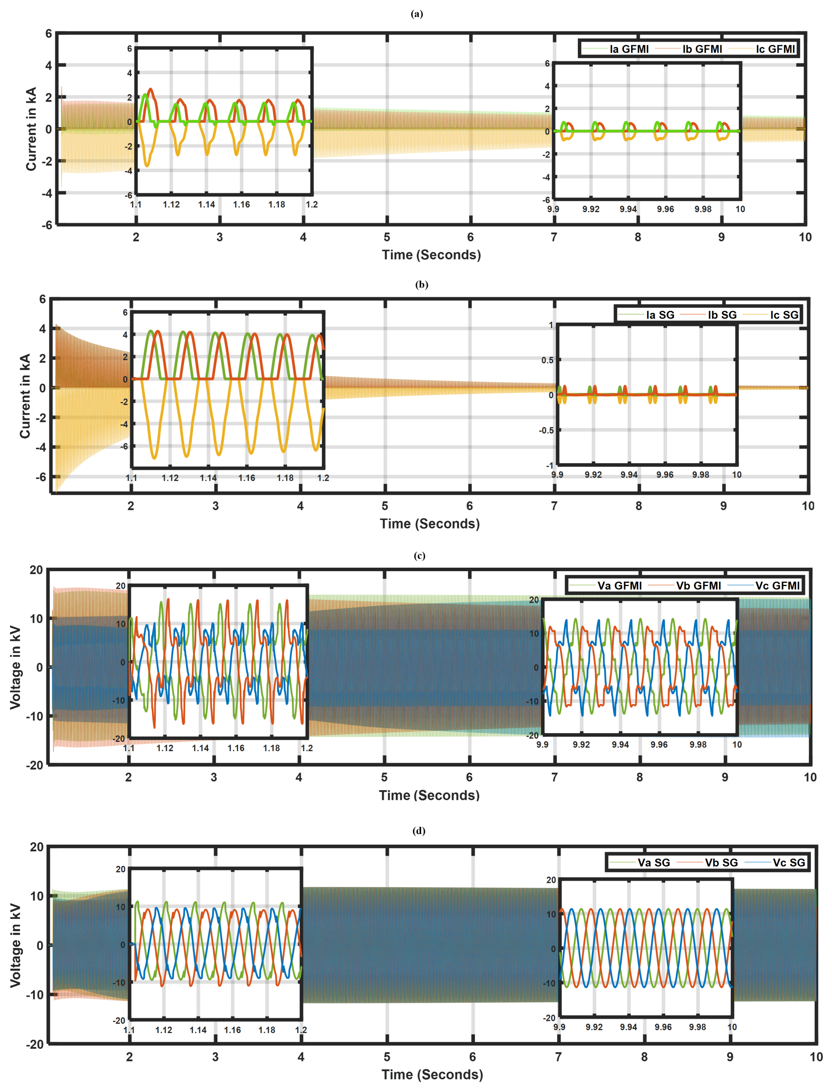
In this subsection, the results of the inrush currents and voltages during the energization of the GSU transformer are investigated. Measurements are captured at the low-side terminal of the GSU transformer. The maximum remnant flux is modeled as +80% phase A, 0% phase B, and −80% phase C. Also, note that the power inverter requires a medium-voltage (MV) transformer that resides between the collector bus and the inverter terminal. A fully detailed model of the MV transformer has been accounted for in this paper, and magnetizing elements such as hysteresis curves and remnant flux are set accordingly as the GSU transformer model. The phase currents from the GSU transformer energization are presented in Figure 3a,b for the GFMI and SG, respectively. The first second of the simulation involves the initialization transients as mentioned earlier. For this reason, time-domain result plots begin after 1 s. Additional inset boxes are also provided to illustrate the detailed waveforms captured during the first 6 cycles (1.1–1.2 s) and the last 6 cycles (9.9–10 s). The initial inrush current peak from the GFMI in Figure 3a was significantly lower than the SG (around 3.8 kA compared to 8 kA) due to the GFMI’s current limiter being active, which is set to 1.2 P.U during this study. The SG (Figure 3b), in contrast, provides a ∼8 kA inrush current peak, which is more than twice the amount of the GFMI case. Inrush currents contain a DC offset as well as a large, distorted AC component that decays to a steady state. The decay rate depends on the circuit X R ratios. It is evident in the SG case that the decay is fast due to the SG’s characteristics such as damper windings and other internal circuit components. Consequently, the GFMI’s case indicates a slow decay with sustained DC offset. Further investigations revealed that this behavior was caused by a sympathetic interaction between the GFMI’s MV transformer and the GSU transformer. Sympathetic inrush occurs when an incoming transformer is energized close to an existing energized transformer. The DC component of the inrush current drawn by the incoming transformer flows through the system resistances, producing a DC voltage component. This forces the existing energized transformers, in this case the inverter MV transformer, to re-saturate, drawing high currents as the flux linkages develop an asymmetrical offset [21,22]. Additional sensitivity studies were performed by disabling the magnetizing models (saturation and hysteresis) in the MV transformer. The results, not included here because of space limitations, showed that the inrush currents at the GSU terminal decayed significantly faster than those for the SG. This study also manifested less distorted voltage waveform output from the GFMI, justifying the absence of sympathetic inrush.
Figure 3c,d shows the phase voltages during the transformer energization for the GFMI and SG, respectively, with inset boxes displaying the waveform details. When comparing the waveform details in the first set of inset boxes which capture the first six cycles of the inrush, the GFMI voltages appear severely distorted and indicate overvoltages in certain phases as compared to the SG case. This is the resulting impact from the asymmetrical fluxes caused by sympathetic inrush. Similar case studies examining the impact of sympathetic inrush between two transformers can be found in [23], which also revealed similar inrush characteristics to those observed in this paper. As the sympathetic inrush decays gradually, the impact on the voltage waveform is also reduced; for instance, the 2nd inset boxes that illustrate the last six cycles of the voltage waveform show no distortions for the SG. Moreover, the GFMI’s case also shows reduced distortions and overvoltages. The observations during the transformer energization when using a GFMI reveal that the sympathetic inrush between the MV and GSU transformers needs to be considered, since the inrush currents are extended for longer durations compared to normal inrush currents from using the SG. Furthermore, as the extended inrush currents are observed to decay at a slower rate, the GFMI needs to be provisioned with current-limiting schemes that can suppress the inrush currents to protect the power inverter from thermal damage caused by overcurrents.

3.3. Impact of Voltage Loop Compensator Gains on Transformer Inrush

Various inverter control schemes have been proposed in the literature. The cascade control scheme is commonly favored, since it separates the voltage loop and current loop controllers, which are typically operated in a d-q axis reference frame. The decoupling of these two control loops enables the user to fine-tune each control loop independently at different bandwidths. The voltage loop in particular regulates the voltage at the capacitor filter, while the current loop regulates the current at the inductor filter [24]. The cascade control scheme is employed in this GFMI model, and the current references generated by the voltage loop can be expressed as
I d r e f = ( E r e f V d ) ( K p + K i s ) + I l d C f ω V q
I q r e f = ( E r e f V q ) ( K p + K i s ) + I l q + C f ω V d
where i d r e f and i q r e f are the d-q axis current references, respectively, E r e f is the voltage reference, and V d and V q are the d-q axis grid voltages. The C f is the capacitor voltage that acts as the feed-forward input and I l d and I l q are the d-q axis grid currents. The feed-forward design is essential in simplifying the controller design, since the current inputs from the grid aid in disturbance rejection [24]. Tuning the compensators is not the scope of this paper, as several publications discuss compensator tuning; however, for completion purposes, the compensator gains can be tuned by formulating the control loop transfer functions and solved using pole-placement methods for the response time and damping ratio. The voltage loop tuning in particular comprises the current loop transfer function and the capacitor voltage ( V d , V q ) transfer function. Since the response time of the voltage loop is higher, the current loop transfer function can be neglected [21,24]. Furthermore, it is a common process for manufacturers to fine-tune compensator gains manually during a plant commissioning phase. Several publications and literature are available that outline the best practices to follow during manual compensator gain tuning.
To examine the impact of how compensator gains can influence the inverter response, sensitivity studies were performed adjusting the voltage loop compensator gains during the transformer energization sequence. A similar sensitivity study was performed in the blackstart assessments referenced in [25]; however, the authors focused on the outer loop P f compensator gains and investigated the overall frequency responses according to the sensitivities conducted. Similarly, in this paper, we evaluate the inverter response using 3 various voltage controller compensator gains as identified in Table 2.
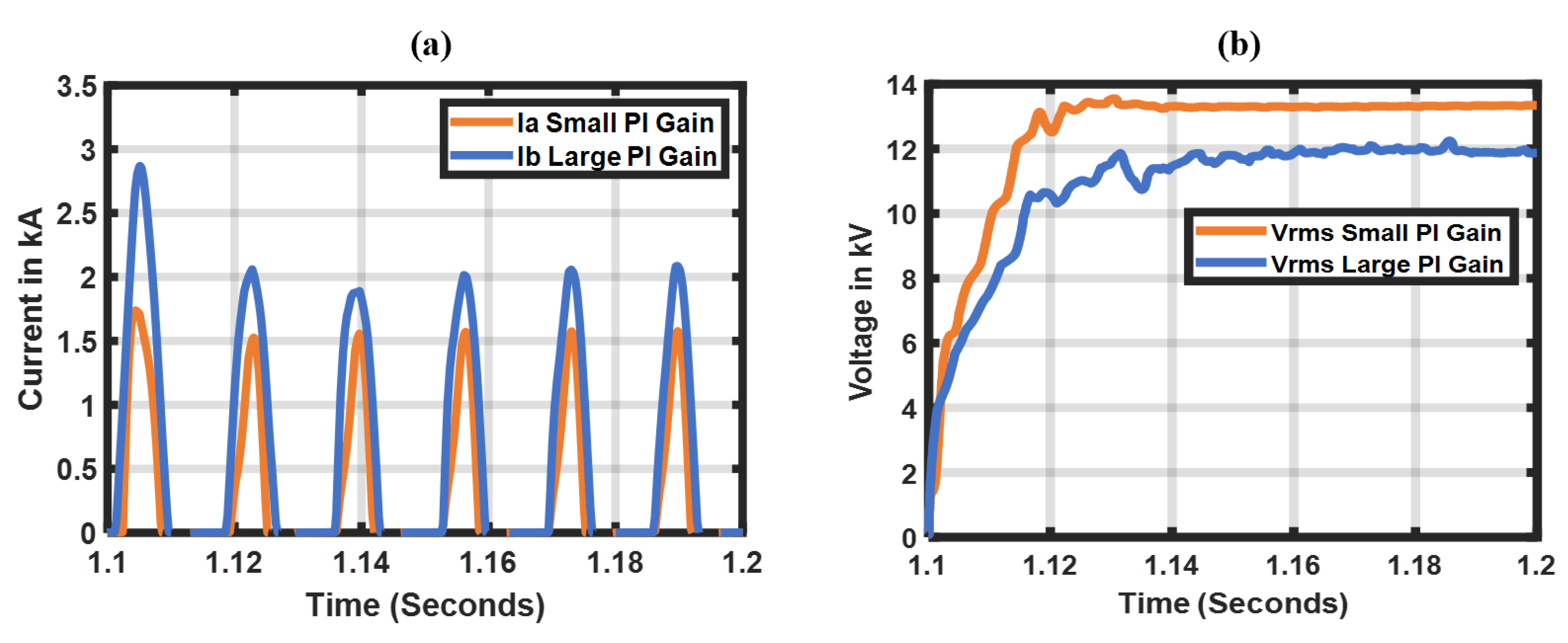
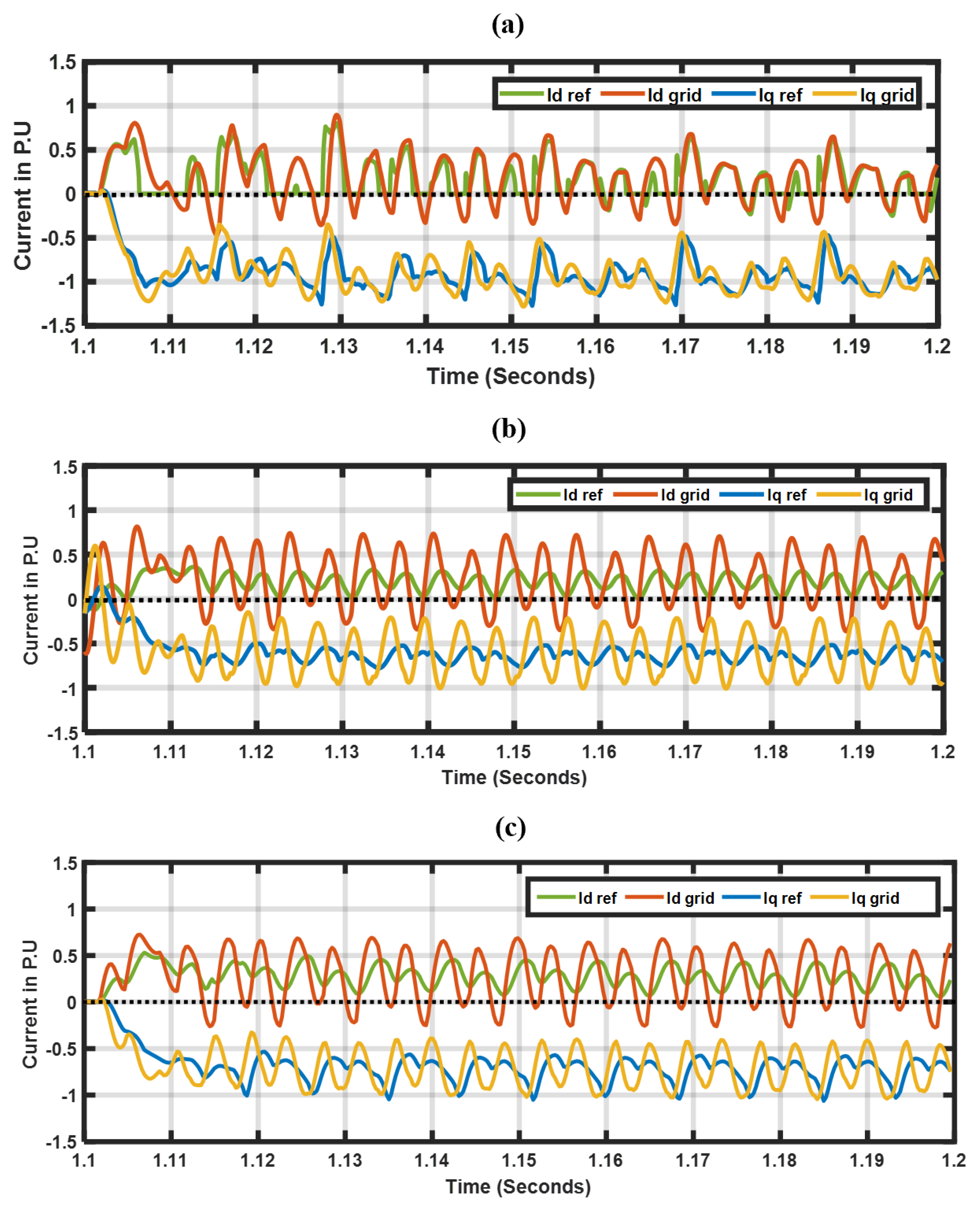
Figure 4a,b demonstrate the phase current and RMS voltage response at the GSU terminal upon energization. Case 1 (Small PI gain) recovers to the nominal voltage (13.8 kV) faster (Figure 4b) and with nearly half the current amplitude peak than case 2 (Figure 4a), which results in a delayed voltage recovery. To further expand on this behavior, Figure 5 is provided to compare the current references generated from the voltage loop to the grid inductor currents. The currents demonstrated in these plots are in the d-q frame for all sensitivity cases during the transformer energization. Case 2 (Figure 5a) illustrates a close coupling behavior between the current references and the inductor currents, which correlate to the larger inrush current amplitudes observed in Figure 4a. This is expected, as the larger PI compensator gains assigned allow the compensators to generate a higher proportional gain coupled with tighter integral gains, which provide a faster response resulting in close tracking of the control loop with the inductor currents. In contrast, when smaller compensator gains are assigned, the current references as shown in Figure 5b lose the close tracking with the inductor currents. The findings from these sensitivity studies indicate that the control loop compensator gains can significantly impact the inverter responses during a blackstart; thus, specific tuning efforts should be considered to achieve an ideal balance and ensure that the inverter does not cause any instabilities.

3.4. Impact of Inverter’s Current-Limiting Scheme on Transformer Inrush Currents

In an IBR, current-limiting strategies are required to prevent the power inverters from exceeding their current output, as the power electronic components are sensitive to heat. An overcurrent condition may cause substantial thermal damage to the power inverter and other various power electronic components, leaving the components inoperable. Several types of current-limiting strategies have been compared in literature [26]. The scheme employed in this model is known as the current saturation or reference modifier scheme [13], which is placed between the voltage and current control loops and uses the abc-frame over the conventional d-q-frame scheme. Current limiting imposed in the abc-frame ensures that phase currents from unbalanced disturbances such as phase-to-ground faults are restricted accordingly per phase. Furthermore, using the current saturation/reference modifier liming scheme has several advantages. When the current limit is exceeded, the scheme modifies the current references directly that were generated by the voltage control loop. The current references are used by the current control loop to generate voltage references for modulating the inverter terminal voltage. Another advantage is that the placement of the limiter in a cascade control scheme couples it with the current control loop dynamics. The current control loop is typically tuned at higher bandwidths than the voltage control loop, and as a result, the current limitation process can restrict the currents at faster speeds. Conceptually, soft energization (SE) also works by modifying reference inputs into the control loops, in particular, SE modifies the voltage reference input in the form of a progressive voltage ramp [12]. When we apply this concept to a cascade control scheme, the voltage reference modification by SE constantly modifies the current references similarly to what this current-limiting scheme does. The logic behind how this current-limiting scheme operates is demonstrated in Equation (3) [17].
I r e f n = 1 · I r e f , for I r e f I M a x ( I M a x I p h M a x ) · I r e f , for I r e f > I M a x
I p h M a x = m a x ( | I a | , | I b | , | I c | )
where I r e f n is the calculated current reference by the limiter, I r e f is the generated current references from the voltage loop, I M a x is the assigned current limit and I p h M a x is the maximum phase current magnitude from ( | I a | , | I b | , | I c | ) observed by the limiter. When the assigned current limit ( I M a x ) is breached, a ratio of the current limit to the maximum phase current magnitude ( I p h M a x ) is used to multiply the current references ( I r e f ) generating the updated references ( I r e f n ), which are used by the current control loop. Analytically, we can formulate the equations used to perform the current limiting. The first step is to convert d-q current references generated from the voltage loop into positive and negative sequences and its phase difference using Equations (5)–(7):
| I 1 | = | I q r e f + | 2 + | I d r e f + | 2
| I 2 | = | I q r e f | 2 + | I d r e f | 2
I 1 I 2 = a t a n 2 | I q r e f + | | I d r e f + | + a t a n 2 | I q r e f | | I d r e f |
where I 1 and I 2 are the positive and negative sequence currents, respectively. I d r e f + , I q r e f + and I d r e f I q r e f are the positive sequence and negative sequence dq-axis current references. The next step is using Equation (8) below to convert the positive and negative sequence current magnitude and phase acquired using Equations (5)–(7) into phase current magnitudes:
| A + B | = | A 2 | + | B 2 | + 2 | A | | B | c o s ( A B )
An example of how phase a current magnitude can be achieved using Equation (8) is demonstrated in Equation (9) (phase b and c current magnitudes are acquired similarly, however, a + 120 and 120 offset is added, respectively):
| I a | = | I 1 2 | + | I 2 2 | + 2 | I 1 | | I 2 | c o s ( I 1 I 2 )
The limiting scheme continuously monitors each phase’s current magnitude current acquired using Equations (5)–(9). The logic as identified in Equation (3) is used to proportionally scale down the current as required.
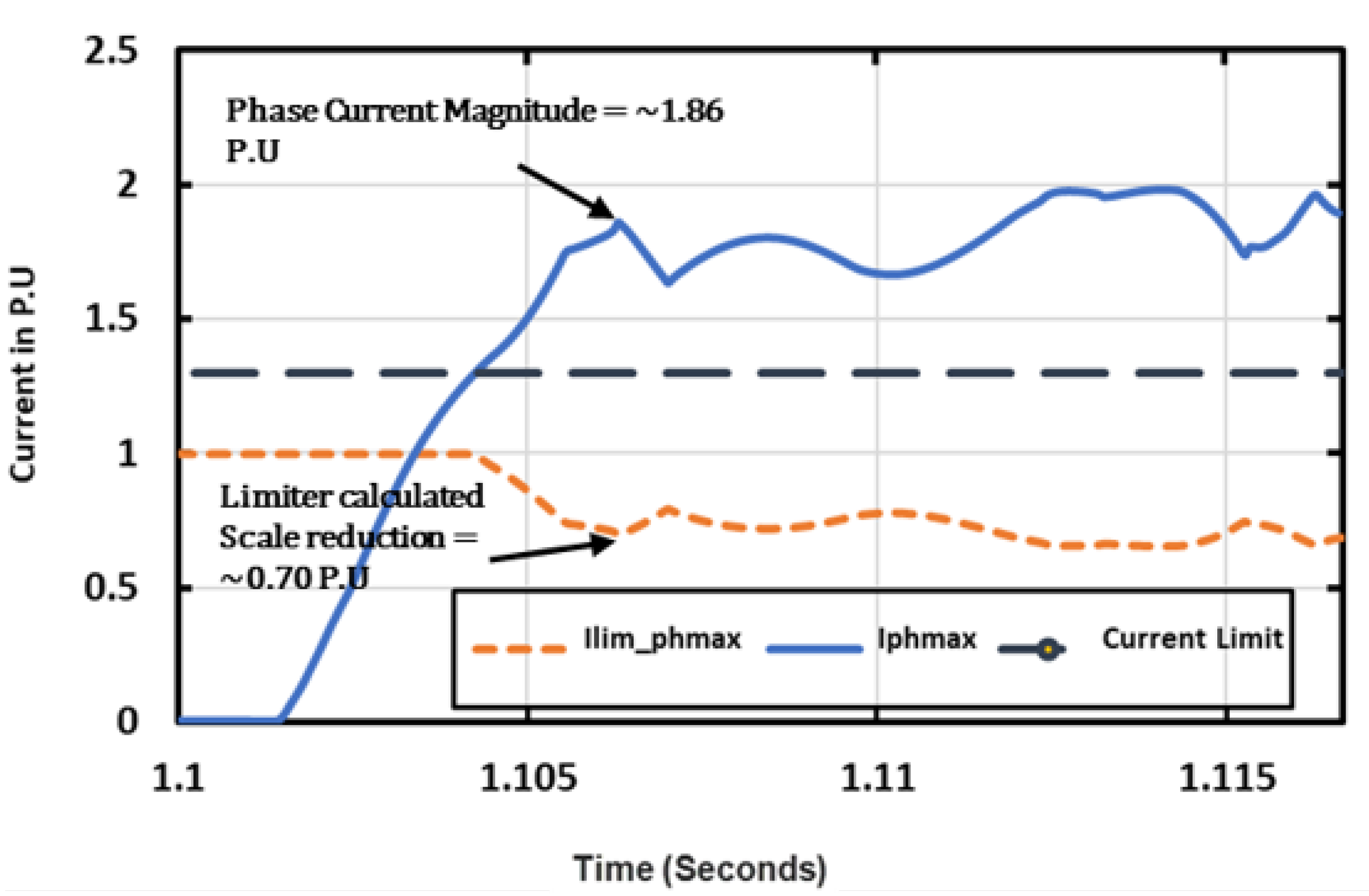
Figure 6 demonstrates how the limiter calculates the scaled current references using a maximum phase magnitude observed at a particular time-point after the GSU transformer is energized. The scaled output is illustrated as 0.7 P.U., when the phase magnitude is observed to reach 1.86 P.U. The current limiter in this example is pre-set to 1.3 P.U. Using the logic in (3) and finding the ratio between the max phase and the pre-set current limit, the value calculates to 0.7 P.U., validating the model output.
To further expand on the limiter behavior during the energization of the GSU transformer, Figure 7a,b demonstrate the limiter activation frequency and the corresponding calculated current scale. The plots demonstrate a ∼2 s duration after the transformer is energized at 1.1 s. An interesting observation is that the limiter is scaling the current substantially during the first few cycles into the inrush current when the transient current is at the highest amplitude. The limiter continued to be activated (1 = On, 0 = Off) in Figure 7a throughout the extended inrush currents as identified in prior sections, which was caused by the sympathetic inrush. Observing Figure 7b, the peaks reduce in correlation with the decay of the inrush current. It was also verified in the case study without the inverter MV transformer magnetizing model (saturation and hysteresis) that the limiter was activated only during the first half cycle of the transformer energization when the current amplitude is at the maximum. The observations of the current limiter behavior suggest the following. (1) The frequency of the limiter activation during the blackstart demonstrates that current-limiting schemes are crucial in ensuring the inverter current outputs are controlled below its threshold. (2) The frequency of the limiter activation also reveals the extent of extended inrush currents generated by the sympathetic interaction between the MV and GSU transformer, emphasizing the importance of GFMIs being provisioned with the appropriate limiting schemes before being considered for blackstart applications.

3.5. Harmonic Distortions from Transformer Energization

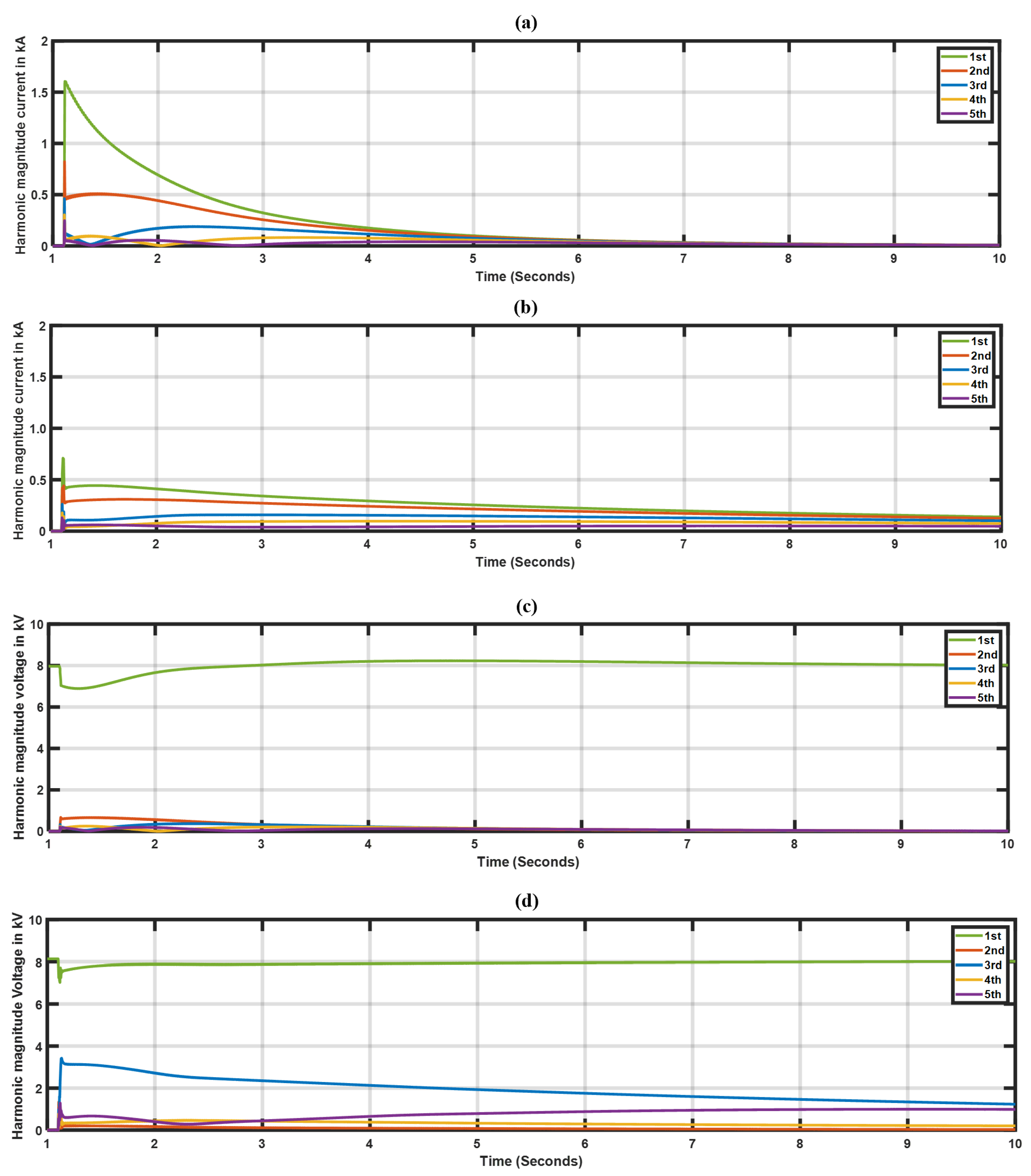
Harmonics are components of periodic waves of voltage and currents at frequencies that are integer multiples of the fundamental or base frequency [27]. Common sources of harmonics are non-linear devices such as power electronic-coupled converters, variable speed drives, loads, etc. The term ‘transient harmonics’ is used in the literature to describe waveforms caused by transients in the power system, such as short-circuit faults and switching in network assets such as transformers, capacitor banks, and reactors. References [27,28] provide an in-depth overview of power system harmonics. Upon energizing a transformer, the inrush currents produce dominant 2nd to 5th harmonic for a few cycles that may sustain to extended periods depending on the network and the extent of the inrush currents. As such, harmonic restraints are routinely used in transformer differential protection. IEEE-519 [29] provides suggested harmonic limits at various voltage levels that are used as a guideline for utilities to ensure the harmonics present in the system are controlled and below the suggested limits. With IBRs, harmonics are a rising concern due to the inverter source’s contribution to harmonics. The IBRs contain filters to filter out high-frequency harmonics from the high-frequency switching of the switches; however, depending on the resonance levels of the network at certain frequencies, the harmonics can be magnified if the harmonic frequencies of the inverters also align with the resonant frequencies of the transmission network. The PSCAD simulator has the capability to convert the Fast Fourier Transform (FFT) evaluating signals into the frequency domain, and a harmonic distortion calculator can be added to extract the total and individual harmonics from the frequency domain converted signals. In this paper, fundamental (60Hz) to 5th harmonic magnitudes are presented for phase A currents and voltages captured at the generator terminal bus and transformed using FFT in Figure 8a,b and c,d, respectively, during the GSU transformer energization phase.
Figure 8a,b, demonstrate the inrush current harmonics for the SG and the GFMI, respectively. As observed, the initial current magnitudes of the SG case are significantly higher; however, similarly to how the inrush current decays, the harmonics also decay faster in contrast to the GFMI’s cases, which show undamped and extended harmonic magnitudes. This harmonic behavior is also a result of the sympathetic interaction of the GSU and inverter MV transformers, which demonstrated a higher DC offset following the same behavior of the inrush currents observed in Figure 3. An interesting observation in the GFMI’s case is that a sustained 3rd harmonic is noticed in both the current and voltage harmonics requiring further investigations as the harmonics are observed at the primary winding of the GSU, which is in a Δ configuration. In the literature, Δ windings are employed to trap zero sequence currents, which are commonly also known as the third harmonic in an unbalanced system [30]. Further investigations indicated that the observed third harmonic is not a zero sequence component, since the system is balanced, but rather a transient harmonic with only positive and negative sequences present. Similar harmonic behavior has been reported in [30] and has been attributed to sympathetic inrush flowing into a Δ winding of a transformer during its energization sequence.
The harmonic observations suggest that the conventional harmonic restraint schemes utilized in existing transformer differential protection schemes may require further modifications in order to successfully perform a blackstart using an IBR. Transformer protection schemes utilize a harmonic restraint that allows the relay to distinguish the harmonics produced from energizing transients from short-circuit fault transients to avoid relay misoperation. The 2nd harmonic is typically used as a percentage ratio to the fundamental to distinguish the transformer energization inrush currents; in addition, the relays also contain a time-delay function that monitors the time of the energization transients decaying. The extended inrush currents from the IBR-based blackstart also reveal that modifications to the time delays of the relay need to be considered to avoid misoperation. It should be noted that if the sequence of the transformer energization is controlled such as adopting the point-on-wave (POW) method which attempts to close the breaker at a certain angle, the transient response from sympathetic inrush is minimized, resulting in a reduction of harmonic distortion. The POW method, however, has drawbacks; for instance, it requires advanced meters and breaker control schemes. Additionally, the breaker closing action can still have delays, resulting in high inrush currents. The preferred method to blackstart using an IBR is to employ the soft energization (SE) approach, as studied in [8,10,12], which demonstrated that when performed effectively, inrush currents from transformer energization are substantially reduced. It should be noted that SE depends on the ramp time duration; that is, a faster ramp time can generate inrush due to the rapid flux-buildup from a faster voltage ramp. Additionally, the present literature on SE neglects the MV transformer. Therefore, some sympathetic interaction could potentially emerge as the voltage ramp cycle approaches nominal voltage.

4. Motor Starting Transients

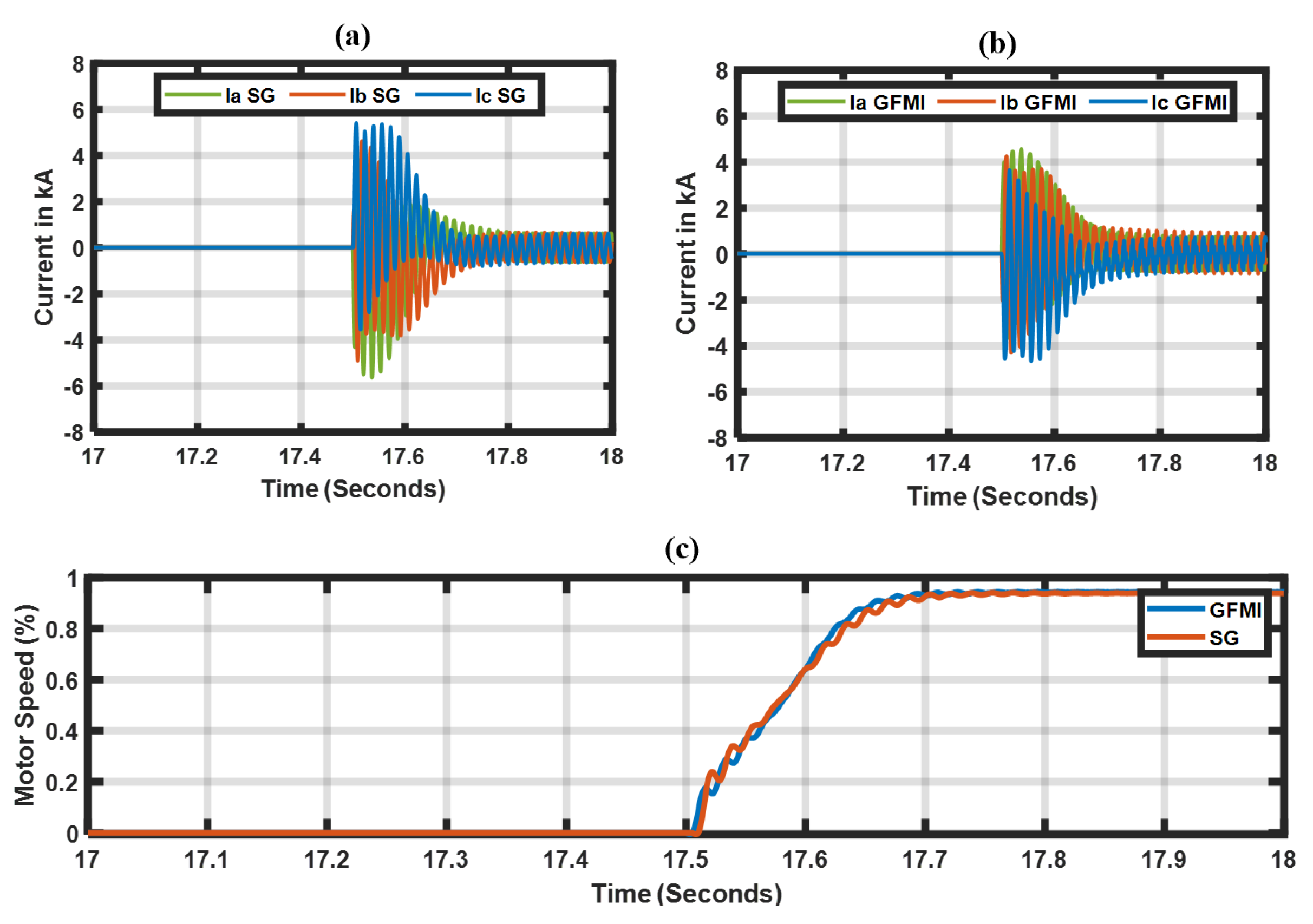
The auxiliary loads at the off-site power plant comprised compressors, pumps, etc.; therefore, an aggregated synchronous motor can be used to represent the rotational load dynamics. During the start-up sequence, the motor draws a large inrush current required to rotate its stator/rotor, which can produce severe voltage dips that can impact the source generator. As the motor approaches the desired speed (typically around 98%), the transients from the starting sequence settle. Utilities typically follow a voltage dip criteria when connecting and starting large rotational loads. It is critical to ensure the frequency of the motor starting and the voltage dips do not impact the system or nearby customer loads. Figure 9a,b demonstrate the start-up inrush currents of a synchronous motor sized to 1.8 MVA, and the presented plots capture the inrush at the motor terminals for both the SG and GFMI cases, respectively. The inrush currents are lower from the GFMI’s case (peaking to ~±4.0 kA) as compared to the SG (peaking to ~±5.8 kA) due to the current limitation of the GFMI (the limiting schemes were observed during this sequence and found to have been activated for a few cycles). Furthermore, Figure 9c demonstrates the motor speed during the motor start sequence. As shown, using both generator sources, the desired motor speed of around 98% can be achieved without any stalling, indicating that the motor started up successfully. The frequency responses between the SG and the GFMI had a ∼0.3 Hz difference, with the SG’s case dipping to 59.3 Hz as compared to 59.7 Hz using the GFMI, which was attributed to its faster frequency response. In contrast, the SG’s slow time constants in the governor results in slower response and recovery. It is important to note that the frequency dips observed are normal during the blackstart process as the system is extremely weak, and it is a common process for utilities to reconfigure or even disable protection schemes to avoid misoperation due to the lower-frequency dips. Additionally, the frequency before synchronizing the off-site power plant with the cranking path should be close to 60 Hz, since any deviations will result in large transients during synchronization, which can potentially trip and black out the cranking path. This would be undesirable, as it would require the cranking path to be re-established again. Regarding the GFMI, the VSM control uses a frequency droop to regulate the frequency; however, since the active power reference ( P r e f ) is set to 0 during the initial stages, it was observed that during load-pick up, the frequency never recovers to 60 Hz. The SG, in contrast, uses an isochronous control mode, which ensures the frequency is constantly regulated by its governor to 60 Hz. To address the frequency recovery issues of the GFMI, this paper proposes an alternative method of using a power plant controller (PPC) to regulate the frequency when necessary as opposed to modifying inverter outer loop controls. The proposed method will be discussed in the following subsection.

Proposed Frequency Restoration Using Power Plant Controller

The GFMI’s active power reference ( P r e f ) is set to 0 to maintain a 60 Hz frequency during the establishment of the cranking path. This is because, during this phase, there are no active power requirements since there are no loads to be picked up. The droop function the GFMI uses can be expressed as [31]
ω = ω 0 + 1 d f ( P r e f P )
where ω , ω 0 , d f , P r e f and P are the total angular frequency, initial angular frequency, frequency droop, active power reference, and active power output, respectively.
To address the frequency restoration, this paper introduces an alternative method using a power plant controller (PPC) to drive the P r e f of the inverter. Similar frequency restoration controllers have been proposed in [8]; however, these are implemented at the inverter level, which can be impractical at the utility-scale, since an industrial renewable energy plant (REP) may contain multiple clusters of inverters to meet the total power output. PPCs, on the other hand, are currently employed in REPs to maintain voltage and frequency at the transmission interconnection point using real-time measurements to process the resulting powers and voltage references delivered to the power inverters. Additionally, the PPC serves as a centralized commander; therefore, the cluster of inverters receives the same reference commands. Another advantage of the PPC is that the configurations can be accessed remotely; therefore, the control schemes could be adjusted as needed without much downtime [32]. Figure 10 illustrates the GFMI blackstart plant with a PPC module integrated, the POI meter provides the real-time measurements which are used as inputs into the PPC which also contains the proposed frequency controller. The proposed controller regulates the P r e f based on the frequency deviation from the desired 60 Hz to the real-time frequency measured at the POI. Proportional and integral (PI) compensators are employed to drive the frequency error to zero. Essentially, taking Equation (10), the function can be modified by adding an additional P r e f n variable to the droop function that can be controlled using a switch logic (1 = On, 0 = Off) during certain scenarios such as blackstart:
ω = ω 0 + 1 d f ( P r e f + ( P r e f n ) P )
P r e f n = ( ( f 0 f p o i ) P I ) P s y n c )
P I = ( K p + K i s )
where P r e f n and P s y n c are the new power reference variable and synchronizing switch status (1 = On, 0 = Off), respectively, and f 0 and f p o i are the nominal and measured frequency in Hz. As P r e f = 0 during the initial blackstart sequence, the synchronizing switch status P s y n c acts as a multiplier of the closed loop PI controller. When the switch is disabled, the overall output is multiplied by 0; therefore, Equation (12) results in 0 not impacting the VSM droop (Equation (11)).
Figure 11 demonstrates the frequency response using the proposed controller and the response without the controller during the motor starting sequence. As illustrated, the frequency regulated by the controller successfully restores the frequency to 60 Hz; in contrast, without the controller implemented, the frequency does not recover to 60 Hz. The response of the controller can be fine-tuned by adjusting the PI compensators. As shown, the overshoot is extremely small in Figure 11, since very tight values have been assigned to the compensators.
Another important aspect to consider with PPCs is the communication time delays since they operate using metered signals as inputs into their control schemes before sending set-point commands to the inverters. Furthermore, the PPC’s controller schemes use compensator gains, which can result in added delays. To address these concerns, a time delay of 150 milliseconds (ms) was implemented to demonstrate the effectiveness of using a PPC in regulating the P r e f value. Figure 12 compares the frequency response when delays are considered. As observed, there are some differences to note: for instance, when considering the delays, the frequency excursion falls to 59.7 Hz, which is expected, since the closed-loop controller response commands sent to the GFMI now contain a delay. These findings suggest that while PPCs can be sufficient in restoring the frequency as evidenced by the results, the GFMIs and the rest of the system’s under-frequency protection settings should be set correctly to ensure no misoperations occur. Other solutions such as considering faster communication devices to reduce the delays to 50 ms could be explored for blackstart-specific GFMIs.

5. Full Cranking Path Energization Results

This section presents a full study of the energization of the cranking path. To complete the cranking path, both blackstart sources need to maintain acceptable voltage and frequency while providing system stability from network asset energization transients. The cranking path includes energizing two transformers and two induction motors, which are started simultaneously with a 10-s time delay to allow transients to settle, and finally, a static constant impedance load rated at 1 MVA is also energized. (Refer to Figure 1 for the cranking path diagram.) The sequence of events used to simulate the full cranking path study is based on a transmission utility’s emergency operational plan (EOP-005) procedure, which is a mandatory NERC compliance requiring every transmission owner to have a blackstart procedure in place [22]. The sequence of events is provided in Table 3.
The time-domain simulation results are illustrated in Figure 13 for both the SG and the GFMI cases. The data were captured at the 13.8 kV generator terminal bus. Figure 13b demonstrates the frequency response from both sources; as illustrated, the GFMI’s response is significantly faster despite using the same inertia constants. In addition, the proposed frequency recovery controller using the PPC is utilized to restore the frequency to 60 Hz. The SG, on the other hand, contains slower time constants used in its controller gains in the governor, resulting in a slower frequency recovery. However, as shown, the frequency is constantly regulated due to the isochronous governor mode. For both the active and reactive power response (Figure 13c,d), the SG provides higher reactive power during the GSU energization, while the GFMI due to its current limiting imposed can only inject ∼50% of the SG’s power. As the transients settle between the various energization phases, its important to observe how both the sources respond very closely. Furthermore, Figure 13a shows a larger voltage dip of the GFMI (blue plot) as compared to the SG at the 11s mark as a result of the motor starting sequence generating a transient inrush current. The voltage dip from the GFMI is due to the additional impedance between the inverter and the GSU transformer (recall, the data are captured at the GSU terminal bus), such as the collection system and MV transformers. In contrast, the SG is modeled as directly connected to the low side of the GSU transformer; moreover, the sub-transient reactances of SGs are substantially low for the first few cycles, which impacts the voltage dip. The observations from Figure 13 demonstrate that the GFMI has the ability to blackstart the system as compared to the conventional SG, addressing one of the common questions currently being asked: Can a GFMI comparably sized to an SG blackstart a system successfully using conventional EOP-005 switching methods?

6. Discussion

A comprehensive assessment has been presented evaluating the differences between an SG and a GFMI during a blackstart sequence studied using time-domain EMT simulations. In particular, this paper investigated the performances of the SG and GFMI during the transformer and rotational load energization sequences, which are known to generate large transient inrush currents, posing substantial challenges to the blackstart unit. The transformer energization results revealed unique inrush features when utilizing a GFMI, such as significant DC offset and extended inrush current durations. Further evaluations demonstrated that the MV and the GSU transformer react sympathetically with each other, creating a sympathetic inrush. As a result, the GFMI’s current-limiting scheme was active for the extended inrush duration, ensuring the inverter is not subjected to an overcurrent condition, proving to be an absolute necessity during an IBR-based blackstart. The limiting scheme in particular acts as a current reference modifier by continuously monitoring the current references which are generated by the voltage control loop. If the current reference violates the assigned current limit, the limiting scheme proportionally reduces the current references influencing the final voltage references. In essence, the reference modifier-limiting scheme behaves similarly to soft energization (SE), which is also performed by modifying the voltage reference. In contrast, the SG’s case demonstrated normal magnetizing inrush behavior with a rapid decay as a result of the source provisioned with damper windings as part of its internal circuit characteristics. In context, the initial inrush current amplitude peak of the GFMI for the first cycle was ∼50% reduced as compared to the case of SG; however, sustained inrush over some time demonstrated higher amplitude peaks.
The harmonic distortions were also evaluated during transformer energization, which resulted in a correlation with the inrush behavior. The GFMI’s case revealed higher magnitude and undamped harmonics; in particular, a 3rd harmonic was continuously observed, which required further investigations since the transformer is in a delta winding configuration, which is typically used to trap the 3rd harmonic (zero sequence currents in an unbalanced system). The investigations revealed this 3rd harmonic to contain only positive and negative sequences; therefore, it can be considered a transient harmonic as a result of the sympathetic inrush resonance. The harmonic distortions during sympathetic inrush were verified and reported in other publications. The observations from the transformer energization studies highlight the importance of modeling the MV transformer models in detail by enabling the magnetizing characteristics of the transformers. Furthermore, the harmonic distortions observed suggest that modifications to the existing protection schemes may be necessary to avoid any relay misoperations. In comparison, the current harmonics of the SG were initially observed to be 40 % higher than those of the GFMI; however, in correspondence to the inrush current behavior, the SG’s harmonics also damp rapidly. In contrast, the GFMI retains a higher amplitude of harmonics over the 10 s time duration, as illustrated in Figure 8a,b. Consequently, the voltage harmonics of the SG are 50% lower than that of the GFMI. In particular, the GFMI’s 3rd harmonic voltage is ∼3 times higher due to the resonance from sympathetic inrush behavior.
The paper also presented a motor-starting analysis for both the SG and GFMI. The results demonstrated comparable start-up sequences of the motor; the GFMI despite the current-limiting scheme being active for a few cycles was able to supply the necessary current for the motor to start up successfully without stalling. The frequency is expected to dip but recover; in the SG’s case, the SG uses an isochronous droop mode, which regulates the frequency to a nominal 60 Hz. In contrast, the GFMI uses a droop-based frequency control. Since the active power reference is set to zero during the initial phase, the frequency never recovers to a nominal 60 Hz. To address this, the paper proposes a closed-loop controller integrated into a power plant controller module (PPC) to restore the frequency. The PPC is used in industrial plants to maintain the voltages and frequency at the transmission point of interconnection; in addition, the controller at the PPC level eliminates the need to modify the inverter, which is beneficial for industrial IBR plants, which can contain several clusters of inverters. The controller functions by driving the power reference of the inverter when a frequency deviation is observed by the controller. The results demonstrated successful frequency recovery after the motor start-up sequence. Furthermore, the paper also investigates the frequency response of the controller when communication delays between the PPC and the inverter are considered. The results revealed that time delays have an impact as the frequency is allowed to dip further, which may require correct frequency trip settings set at the inverter.
Finally, a full cranking-path energization study is presented comparing the SG and GFMI. Although the results from the detailed transformer and motor energization sequences indicated that the GFMI and SG have discrepancies in how they respond during the transient conditions, the overall behavior during the blackstart sequence is similar once the transient conditions settle. The results from the paper also indicate that when the GFMI is provisioned with the appropriate control loop compensator gains and current-limiting schemes, the GFMI can successfully blackstart a bulk power system using conventional hard switching methods. The GFMI provides ∼50% faster voltage and frequency recovery due to the faster controller gain response, as evidenced in Figure 13. Although the work presented in this paper demonstrated that the GFMI can successfully blackstart the system using the conventional hard switching method, the soft energization (SE) method is recommended for establishing the cranking path, as this method when effectively utilized has been demonstrated to reduce inrush transients.

7. Conclusions and Future Work

Grid-forming inverters have renewed an interest in the academic and industrial communities in further exploring their abilities to provide blackstart services. In that context, this paper presented a practical EMT study analyzing the potential capabilities of GFMIs in the blackstart setting and comparing its performance to the conventional SG. In summary, the contributions of this paper are outlined below:
  • A detailed study comparison between a GFMI and a conventional SG during a blackstart: Transformer and rotational motor load energization sequences were evaluated in detail, as a result, the findings reveal differences between the GFMI and SG; nonetheless, the studies demonstrate that the GFMI can blackstart a bulk power system using conventional hard-energization switching methods.
  • Evaluation of the current-limiting schemes: These schemes are employed to protect the power inverter from the large inrush currents during the transformer and rotational motor load energization sequences. Furthermore, our investigations revealed that this current-limiting scheme behaves similarly to the SE method, which is executed by modifying the references of the GFMI. The findings provided in [13] support our observations.
  • Investigation of voltage and current harmonic distortions: The results demonstrated that the sympathetic interaction between the inverter’s medium voltage (MV) and plant step-up transformer generates extended inrush currents and over-voltages resulting in higher harmonic distortions, which may require the protection relays to be adjusted.
  • Proposing an alternative method of restoring frequency after load pick-up by integrating a closed-loop controller in a power plant controller module (PPC). This method is beneficial because it eliminates inverter-level control modifications. Communication delays between the PPC and inverter are also considered.
For future research, further studies on the soft energization (SE) method will be conducted, employing detailed models of the MV transformers to quantify any adverse impacts observed during the SE process. Another extension of this research would be to investigate several IBR sites participating in a blackstart using the SE method and to assess the impact of various control loop compensator gains applied to each IBR site. Furthermore, evaluating the impacts of various limiting methods such as voltage limiters, virtual impedance-based limiters, etc. during a blackstart could provide interesting insights, since these schemes, as revealed in this paper, are critical in ensuring the IBR can successfully blackstart the system.

Author Contributions

Conceptualization, H.K. and S.R.; Methodology, H.K., S.R., D.R. and O.L.; Software, H.K.; Validation, S.R., D.R. and J.R.; Formal analysis, H.K.; Investigation, H.K.; Data curation, H.K.; Writing—original draft, H.K.; Writing—review & editing, H.K., S.R., D.R., O.L. and J.R.; Supervision, S.R., D.R. and O.L.; Project administration, O.L. All authors have read and agreed to the published version of the manuscript.

Funding

This research was partially supported by the funding from the Electric Utility Management Program (EUMP) at the New Mexico State University.

Data Availability Statement

No new data were created or analyzed in this study. Data sharing is not applicable to this article.

Conflicts of Interest

Author Jose Ribeiro was employed by the Florida Power and Light Company (FPL). The remaining authors declare that the research was conducted in the absence of any commercial or financial relationships that could be construed as a potential conflict of interest.

References

  1. Rathnayake, D.B.; Akrami, M.; Phurailatpam, C.; Me, S.P.; Hadavi, S.; Jayasinghe, G.; Zabihi, S.; Bahrani, B. Grid Forming Inverter Modeling, Control, and Applications. IEEE Access 2021, 9, 114781–114807. [Google Scholar] [CrossRef]
  2. Schöley, A.; Jeinsch, T. Stability Investigation of PLL-Based Grid Synchronization. In Proceedings of the 2021 25th International Conference on Methods and Models in Automation and Robotics (MMAR), Międzyzdroje, Poland, 23–26 August 2021; pp. 233–238. [Google Scholar] [CrossRef]
  3. Special consideration in power system restoration. The second working group report. IEEE Trans. Power Syst. 1994, 9, 15–21. [CrossRef]
  4. Grid Forming Inverters: EPRI Tutorial (2023); Report 3002028090; EPRI: Palo Alto, CA, USA, 2023.
  5. Program on Technology Innovation: Benefit of Fast Reactive Power Response from Inverters in Supporting Stability of Weak Distribution Systems: A Use Case of Grid Forming Inverters and their Performance Requirements; Report 3002020197; EPRI: Palo Alto, CA, USA, 2020.
  6. Ramasubramanian, D. Performance Requirements for Grid Forming Inverter Based Power Plant in Microgrid Applications; Technical Report 3002024431; Electric Power Research Institute (EPRI): Palo Alto, CA, USA, 2022. [Google Scholar]
  7. UNIFI Consortium. UNIFI Specifications for Grid-Forming Inverter-Based Resources—Version 2; UNIFI-2024-2-1; National Renewable Energy Laboratory: Golden, CO, USA, 2024. [Google Scholar]
  8. Alassi, A.; Feng, Z.; Ahmed, K.; Syed, M.; Egea-Alvarez, A.; Foote, C. Grid-forming VSM control for black-start applications with experimental PHiL validation. Int. J. Electr. Power Energy Syst. 2023, 151, 109119. [Google Scholar] [CrossRef]
  9. Sakamuri, J.N.; Göksu, Ö.; Bidadfar, A.; Saborío-Romano, O.; Jain, A.; Cutululis, N.A. Black Start by HVdc-connected Offshore Wind Power Plants. In Proceedings of the IECON 2019—45th Annual Conference of the IEEE Industrial Electronics Society, Lisbon, Portugal, 14–17 October 2019; Volume 1, pp. 7045–7050. [Google Scholar] [CrossRef]
  10. Jain, A.; Saborío-Romano, O.; Sakamuri, J.N.; Cutululis, N.A. Blackstart from HVDC-connected offshore wind: Hard versus soft energization. IET Renew. Power Gener. 2021, 15, 127–138. [Google Scholar] [CrossRef]
  11. Alassi, A.; Ahmed, K.H.; Egea-Alvarez, A.; Foote, C. Transformer Inrush Current Mitigation Techniques for Grid-Forming Inverters Dominated Grids. IEEE Trans. Power Deliv. 2023, 38, 1610–1620. [Google Scholar] [CrossRef]
  12. Alassi, A.; Ahmed, K.; Egea-Alvarez, A.; Foote, C. Soft Transformer Energization: Ramping Time Estimation Method for Inrush Current Mitigation. In Proceedings of the 2021 56th International Universities Power Engineering Conference (UPEC), Middlesbrough, UK, 31 August–3 September 2021; pp. 1–6. [Google Scholar] [CrossRef]
  13. Shahparasti, M.; Laaksonen, H.; Kauhaniemi, K.; Lauttamus, P.; Strandberg, S.; Strandberg, J. Inrush Current Management During Medium Voltage Microgrid Black Start With Battery Energy Storage System. IEEE Access 2022, 10, 42287–42296. [Google Scholar] [CrossRef]
  14. Salient and Non-Salient Models for Synchronous Generator. Available online: https://www.pscad.com/knowledge-base/article/292 (accessed on 17 June 2024).
  15. Viawan, F.; Banktavakoli, R. Power System Restoration: Blackstart Studies. In Proceedings of the 2018 Conference on Power Engineering and Renewable Energy (ICPERE), Solo, Indonesia, 29–31 October 2018; IEEE: Piscataway, NJ, USA, 2018. [Google Scholar]
  16. 3-Phase 2-Winding Transformer. 2003. Available online: https://www.pscad.com/webhelp-v502-ol/Master_Library_Models/Transformers/Classical/3p2w_tx.htm (accessed on 28 May 2024).
  17. EPRI. UNIFI Consortium Work Progress: 2022–2023; Report 3002024431; Electric Power Research Institute (EPRI): Palo Alto, CA, USA, 2024. [Google Scholar]
  18. IEEE 2800; IEEE Standard for Interconnection and Interoperability of Inverter-Based Resources (IBRs) Interconnecting with Associated Transmission Electric Power Systems. IEEE Standards Association: Piscataway, NJ, USA, 2022.
  19. Alassi, A.; Ahmed, K.; Egea-Alvarez, A.; Ellabban, O. Performance Evaluation of Four Grid-Forming Control Techniques with Soft Black-Start Capabilities. In Proceedings of the 2020 9th International Conference on Renewable Energy Research and Application (ICRERA), Glasgow, UK, 27–30 September 2020; pp. 221–226. [Google Scholar] [CrossRef]
  20. Jain, A.; Sakamuri, J.N.; Cutululis, N.A. Grid-forming control strategies for black start by offshore wind power plants. Wind. Energy Sci. 2020, 4, 1297–1313. [Google Scholar] [CrossRef]
  21. Qorai, T.; Gruson, F.; Colas, F.; Guillaud, X.; Debry, M.S. Tuning of Cascaded Controllers for Robust Grid-Forming Voltage Source Converter. In Proceedings of the Power Systems Computation Conference (PSCC), Dublin, Ireland, 11–15 June 2018. [Google Scholar]
  22. Available online: https://www.nerc.com/pa/Stand/Reliability%20Standards/EOP-005-2.pdf (accessed on 17 June 2024).
  23. Bronzeado, H.; De Jesus, N. Sympathetic Interaction Phenomenon in Series-Connected Power Transformers. In Proceedings of the XIII Conferência Brasileira Sobre Qualidade da Energia Elétrica—CBQEE 2019, São Caetano, Brazil, 1–4 September 2019. [Google Scholar]
  24. Amirnaser Yazdani, R.I. Voltage-Sourced Converters in Power Systems: Modeling, Control, and Applications; IEEE Press: Piscataway, NJ, USA; John Wiley & Sons: Hoboken, NJ, USA, 2010. [Google Scholar]
  25. Konstantinopoulos, S.; Ramasubramanian, D.; Farantatos, E.; Singhvi, V. Blackstart and restoration of 100% renewable power systems with grid forming converters. In Proceedings of the 2022 IEEE Power & Energy Society General Meeting (PESGM), Denver, CO, USA, 17–21 July 2022; IEEE: Piscataway, NJ, USA, 2022. [Google Scholar]
  26. Fan, B.; Liu, T.; Zhao, F.; Wu, H.; Wang, X. A Review of Current-Limiting Control of Grid-Forming Inverters Under Symmetrical Disturbances. IEEE Open J. Power Electron. 2022, 3, 955–969. [Google Scholar] [CrossRef]
  27. Sutherland, P.E. Harmonics in electrical power systems: Effects of new technologies. In Proceedings of the 2014 IEEE Industry Application Society Annual Meeting, Vancouver, BC, Canada, 5–9 October 2014; pp. 1–13. [Google Scholar] [CrossRef]
  28. Maslowski, W. Harmonics in power systems. In Proceedings of the Proceedings: Electrical Electronics Insulation Conference and Electrical Manufacturing & Coil Winding Conference, Rosemont, IL, USA, 18–21 September 1995; pp. 37–44. [Google Scholar] [CrossRef]
  29. IEEE Std 519-2022 (Revision of IEEE Std 519-2014); IEEE Standard for Harmonic Control in Electric Power Systems. IEEE Standards Association: Piscataway, NJ, USA, 2022.
  30. Wang, Y.; Yuan, Y.; Lu, Y. Effects and suppression methods for inrush-caused unbalanced third harmonic on Transformer Delta-side. Autom. Electr. Power Syst. 2015, 39, 145–151. [Google Scholar]
  31. Matevosyan, J.; Badrzadeh, B.; Prevost, T.; Quitmann, E.; Ramasubramanian, D.; Urdal, H.; Achilles, S.; MacDowell, J.; Hsien Huang, S.; Vital, V.; et al. Grid-Forming Inverters: Are They the Key for High Renewable Penetration? IEEE Power Energy Mag. 2023, 21, 77–86. [Google Scholar] [CrossRef]
  32. Bullich-Massague, E.; Ferrer-San-Jose, R.; Aragues-Penalba, M.; Serrano-Salamanca, L.; Pacheco-Navas, C.; Gomis-Bellmunt, O. Power Plant Control in Large Scale PV Plants. Design, Implementation and Validation in a 9.4 MW PV Plant. Available online: https://upcommons.upc.edu/bitstream/handle/2117/88080/PowerPlantControl.pdf (accessed on 31 March 2024).
Figure 1. An example of a blackstart cranking-path.
Energies 17 04067 g001
Figure 2. Grid-forming inverter architecture, positive sequence loop in black, negative sequence loop in red (used with permissions from [17]).
Energies 17 04067 g002
Figure 3. Transformer energization transients: (a) 3-phase currents (GFMI), (b) 3-phase currents (SG), (c) 3-phase voltage (GFMI), (d) 3-phase voltage (SG).
Energies 17 04067 g003
Figure 4. Impact of PI compensator gains on the GFMI’s response: (a) phase A current, (b) RMS voltage.
Energies 17 04067 g004
Figure 5. Current control loop response (Id ref, Id grid, Iq ref, Iq grid = D-axis current reference, D-axis inductor current, Q-axis current reference and Q-axis inductor current, respectively)—(a) case 2—large PI gain, (b) case 1—small PI gain, (c) basecase.
Energies 17 04067 g005
Figure 6. Verification of current-limiting model.
Energies 17 04067 g006
Figure 7. Current limiter during transformer inrush: (a) activation frequency (1 = on, 0 = off), (b) current reference scaler.
Energies 17 04067 g007
Figure 8. Harmonic distortions during transformer energization: (a) currents (SG), (b) currents (GFMI), (c) voltage (SG), (d) voltage (GFMI).
Energies 17 04067 g008
Figure 9. Motor starting sequence: (a) motor inrush current—SG case, (b) motor inrush cur-rent—GFMI case, (c) motor start-up speed.
Energies 17 04067 g009
Figure 10. Illustration of a GFMI blackstart resource with a PPC module.
Energies 17 04067 g010
Figure 11. Frequency restoration results of GFMI using the proposed controller.
Energies 17 04067 g011
Figure 12. Frequency restoration results when delays are considered.
Energies 17 04067 g012
Figure 13. Comparison of the cranking-path energization between SG and GFMI: (a) voltage RMS, (b), frequency, (c) active power, (d) reactive power.
Energies 17 04067 g013
Table 1. Case parameters.
Grid-Forming Inverter (GFMI) Parameters
Rating (MVA)40
Current limit (P.U)1.2
Voltage limit (P.U)1.1
Voltage loop compensator gains ( K p , K i s )3, 10
Synthetic inertia (J)3.78
Active power limits (P.U), Min, Max0, 0.8
Reactive power limits (P.U), Min, Max−1, 1
Synchronous Generator (SG) Parameters
Rating (MVA)40
Inertia (J)3.78
Voltage (kV)13.8
GFMI Medium-Voltage (MV) Transformer Parameters
Voltage (LV, HV)0.65 kV, 13.8 kV
Rating (MVA)40
Residual flux ( ϕ r ) a b c (P.U)0.1, 0, −0.1
Saturation voltage knee slope (P.U)1.17
Blackstart Generator Step-Up (GSU) Transformer Parameters
Voltage (LV, HV)13.8 kV, 230 kV
Rating (MVA)80
Residual flux ( ϕ r ) a b c (P.U)0.8, 0, −0.8
Saturation voltage knee slope (P.U)1.17
CT Generator Step-Up (GSU) Transformer Parameters
Voltage (LV, HV)18 kV, 230 kV
Rating (MVA)280
Residual flux ( ϕ r ) a b c (P.U)0.8, 0, −0.8
Saturation voltage knee slope (P.U)1.17
Induction Motor Parameters
Rating (MVA)1.8
Inertia (J)0.49
Voltage (kV)4.16
Table 2. Voltage compensator gain sensitivities.
CaseKpKi/sResults
Basecase310Original basecase
Case 123Low peak current, faster voltage response
Case 23010High peak current, slow voltage response
Table 3. Simulation events of the cranking-path sequence.
StageTimeEvent
11.1 sGSU transformer energization
24.6 s230 kV collector bus is energized
36.1 s230 kV/18 kV transformer is energized
49.1 s18 kV bus is energized
511.1 sRotational load (Motor # 1 energized)
620.1 sRotational load (Motor # 2 energized)
730.1 sStatic load energized
Disclaimer/Publisher’s Note: The statements, opinions and data contained in all publications are solely those of the individual author(s) and contributor(s) and not of MDPI and/or the editor(s). MDPI and/or the editor(s) disclaim responsibility for any injury to people or property resulting from any ideas, methods, instructions or products referred to in the content.